JP6629569B2 - Fluid sterilizer - Google Patents
Fluid sterilizer Download PDFInfo
- Publication number
- JP6629569B2 JP6629569B2 JP2015216983A JP2015216983A JP6629569B2 JP 6629569 B2 JP6629569 B2 JP 6629569B2 JP 2015216983 A JP2015216983 A JP 2015216983A JP 2015216983 A JP2015216983 A JP 2015216983A JP 6629569 B2 JP6629569 B2 JP 6629569B2
- Authority
- JP
- Japan
- Prior art keywords
- housing
- fluid
- flow path
- light source
- ultraviolet light
- Prior art date
- Legal status (The legal status is an assumption and is not a legal conclusion. Google has not performed a legal analysis and makes no representation as to the accuracy of the status listed.)
- Active
Links
- 239000012530 fluid Substances 0.000 title claims description 111
- 230000001954 sterilising effect Effects 0.000 claims description 43
- 238000004659 sterilization and disinfection Methods 0.000 claims description 37
- 239000012510 hollow fiber Substances 0.000 claims description 27
- 230000001678 irradiating effect Effects 0.000 claims description 13
- 238000007789 sealing Methods 0.000 claims description 12
- 239000012528 membrane Substances 0.000 claims description 6
- 238000011144 upstream manufacturing Methods 0.000 claims description 3
- 239000000565 sealant Substances 0.000 description 13
- 239000000463 material Substances 0.000 description 9
- 229920001343 polytetrafluoroethylene Polymers 0.000 description 6
- 239000004810 polytetrafluoroethylene Substances 0.000 description 6
- XLYOFNOQVPJJNP-UHFFFAOYSA-N water Substances O XLYOFNOQVPJJNP-UHFFFAOYSA-N 0.000 description 6
- 229910052782 aluminium Inorganic materials 0.000 description 4
- XAGFODPZIPBFFR-UHFFFAOYSA-N aluminium Chemical compound [Al] XAGFODPZIPBFFR-UHFFFAOYSA-N 0.000 description 4
- 230000000694 effects Effects 0.000 description 4
- 238000005192 partition Methods 0.000 description 4
- 229920005989 resin Polymers 0.000 description 4
- 239000011347 resin Substances 0.000 description 4
- OKTJSMMVPCPJKN-UHFFFAOYSA-N Carbon Chemical compound [C] OKTJSMMVPCPJKN-UHFFFAOYSA-N 0.000 description 2
- YCKRFDGAMUMZLT-UHFFFAOYSA-N Fluorine atom Chemical compound [F] YCKRFDGAMUMZLT-UHFFFAOYSA-N 0.000 description 2
- VYPSYNLAJGMNEJ-UHFFFAOYSA-N Silicium dioxide Chemical compound O=[Si]=O VYPSYNLAJGMNEJ-UHFFFAOYSA-N 0.000 description 2
- 239000010419 fine particle Substances 0.000 description 2
- 229910052731 fluorine Inorganic materials 0.000 description 2
- 239000011737 fluorine Substances 0.000 description 2
- 238000012423 maintenance Methods 0.000 description 2
- 238000000034 method Methods 0.000 description 2
- 238000012986 modification Methods 0.000 description 2
- 230000004048 modification Effects 0.000 description 2
- TWNQGVIAIRXVLR-UHFFFAOYSA-N oxo(oxoalumanyloxy)alumane Chemical compound O=[Al]O[Al]=O TWNQGVIAIRXVLR-UHFFFAOYSA-N 0.000 description 2
- 238000000746 purification Methods 0.000 description 2
- 239000000126 substance Substances 0.000 description 2
- 229910002601 GaN Inorganic materials 0.000 description 1
- 239000004695 Polyether sulfone Substances 0.000 description 1
- RNQKDQAVIXDKAG-UHFFFAOYSA-N aluminum gallium Chemical compound [Al].[Ga] RNQKDQAVIXDKAG-UHFFFAOYSA-N 0.000 description 1
- 230000000844 anti-bacterial effect Effects 0.000 description 1
- 229910052785 arsenic Inorganic materials 0.000 description 1
- RQNWIZPPADIBDY-UHFFFAOYSA-N arsenic atom Chemical compound [As] RQNWIZPPADIBDY-UHFFFAOYSA-N 0.000 description 1
- 238000013461 design Methods 0.000 description 1
- 230000006866 deterioration Effects 0.000 description 1
- 238000010586 diagram Methods 0.000 description 1
- 239000000428 dust Substances 0.000 description 1
- 229910052751 metal Inorganic materials 0.000 description 1
- 239000002184 metal Substances 0.000 description 1
- 239000007769 metal material Substances 0.000 description 1
- 239000011368 organic material Substances 0.000 description 1
- 229920002492 poly(sulfone) Polymers 0.000 description 1
- 229920006393 polyether sulfone Polymers 0.000 description 1
- 239000002952 polymeric resin Substances 0.000 description 1
- -1 polytetrafluoroethylene Polymers 0.000 description 1
- 238000010248 power generation Methods 0.000 description 1
- 238000012545 processing Methods 0.000 description 1
- 229920003002 synthetic resin Polymers 0.000 description 1
- 229920002803 thermoplastic polyurethane Polymers 0.000 description 1
- 238000002834 transmittance Methods 0.000 description 1
Images


Classifications
-
- C—CHEMISTRY; METALLURGY
- C02—TREATMENT OF WATER, WASTE WATER, SEWAGE, OR SLUDGE
- C02F—TREATMENT OF WATER, WASTE WATER, SEWAGE, OR SLUDGE
- C02F1/00—Treatment of water, waste water, or sewage
- C02F1/30—Treatment of water, waste water, or sewage by irradiation
- C02F1/32—Treatment of water, waste water, or sewage by irradiation with ultraviolet light
- C02F1/325—Irradiation devices or lamp constructions
-
- A—HUMAN NECESSITIES
- A61—MEDICAL OR VETERINARY SCIENCE; HYGIENE
- A61L—METHODS OR APPARATUS FOR STERILISING MATERIALS OR OBJECTS IN GENERAL; DISINFECTION, STERILISATION OR DEODORISATION OF AIR; CHEMICAL ASPECTS OF BANDAGES, DRESSINGS, ABSORBENT PADS OR SURGICAL ARTICLES; MATERIALS FOR BANDAGES, DRESSINGS, ABSORBENT PADS OR SURGICAL ARTICLES
- A61L2/00—Methods or apparatus for disinfecting or sterilising materials or objects other than foodstuffs or contact lenses; Accessories therefor
- A61L2/02—Methods or apparatus for disinfecting or sterilising materials or objects other than foodstuffs or contact lenses; Accessories therefor using physical phenomena
- A61L2/08—Radiation
- A61L2/10—Ultra-violet radiation
-
- B—PERFORMING OPERATIONS; TRANSPORTING
- B01—PHYSICAL OR CHEMICAL PROCESSES OR APPARATUS IN GENERAL
- B01D—SEPARATION
- B01D63/00—Apparatus in general for separation processes using semi-permeable membranes
- B01D63/02—Hollow fibre modules
-
- C—CHEMISTRY; METALLURGY
- C02—TREATMENT OF WATER, WASTE WATER, SEWAGE, OR SLUDGE
- C02F—TREATMENT OF WATER, WASTE WATER, SEWAGE, OR SLUDGE
- C02F1/00—Treatment of water, waste water, or sewage
- C02F1/44—Treatment of water, waste water, or sewage by dialysis, osmosis or reverse osmosis
-
- A—HUMAN NECESSITIES
- A61—MEDICAL OR VETERINARY SCIENCE; HYGIENE
- A61L—METHODS OR APPARATUS FOR STERILISING MATERIALS OR OBJECTS IN GENERAL; DISINFECTION, STERILISATION OR DEODORISATION OF AIR; CHEMICAL ASPECTS OF BANDAGES, DRESSINGS, ABSORBENT PADS OR SURGICAL ARTICLES; MATERIALS FOR BANDAGES, DRESSINGS, ABSORBENT PADS OR SURGICAL ARTICLES
- A61L2202/00—Aspects relating to methods or apparatus for disinfecting or sterilising materials or objects
- A61L2202/10—Apparatus features
- A61L2202/11—Apparatus for generating biocidal substances, e.g. vaporisers, UV lamps
-
- C—CHEMISTRY; METALLURGY
- C02—TREATMENT OF WATER, WASTE WATER, SEWAGE, OR SLUDGE
- C02F—TREATMENT OF WATER, WASTE WATER, SEWAGE, OR SLUDGE
- C02F2201/00—Apparatus for treatment of water, waste water or sewage
- C02F2201/32—Details relating to UV-irradiation devices
- C02F2201/322—Lamp arrangement
- C02F2201/3222—Units using UV-light emitting diodes [LED]
-
- C—CHEMISTRY; METALLURGY
- C02—TREATMENT OF WATER, WASTE WATER, SEWAGE, OR SLUDGE
- C02F—TREATMENT OF WATER, WASTE WATER, SEWAGE, OR SLUDGE
- C02F2201/00—Apparatus for treatment of water, waste water or sewage
- C02F2201/32—Details relating to UV-irradiation devices
- C02F2201/322—Lamp arrangement
- C02F2201/3223—Single elongated lamp located on the central axis of a turbular reactor
-
- C—CHEMISTRY; METALLURGY
- C02—TREATMENT OF WATER, WASTE WATER, SEWAGE, OR SLUDGE
- C02F—TREATMENT OF WATER, WASTE WATER, SEWAGE, OR SLUDGE
- C02F2201/00—Apparatus for treatment of water, waste water or sewage
- C02F2201/32—Details relating to UV-irradiation devices
- C02F2201/322—Lamp arrangement
- C02F2201/3228—Units having reflectors, e.g. coatings, baffles, plates, mirrors
-
- C—CHEMISTRY; METALLURGY
- C02—TREATMENT OF WATER, WASTE WATER, SEWAGE, OR SLUDGE
- C02F—TREATMENT OF WATER, WASTE WATER, SEWAGE, OR SLUDGE
- C02F2301/00—General aspects of water treatment
- C02F2301/02—Fluid flow conditions
- C02F2301/022—Laminar
-
- C—CHEMISTRY; METALLURGY
- C02—TREATMENT OF WATER, WASTE WATER, SEWAGE, OR SLUDGE
- C02F—TREATMENT OF WATER, WASTE WATER, SEWAGE, OR SLUDGE
- C02F2303/00—Specific treatment goals
- C02F2303/04—Disinfection
Description
本発明は、流体殺菌装置に関し、特に、紫外光を照射して流体を殺菌する技術に関する。 The present invention relates to a fluid sterilization apparatus, and more particularly to a technique for irradiating ultraviolet light to sterilize a fluid.
紫外光には殺菌能力があることが知られており、医療や食品加工の現場などでの殺菌処理に紫外光を照射する装置が用いられている。また、水などの流体に紫外光を照射することで、流体を連続的に殺菌する装置も用いられている。このような装置として、例えば、直管状の金属パイプで形成される流路の管端部内壁に紫外線LEDを配置した装置が挙げられる(例えば、特許文献1参照)。 It is known that ultraviolet light has a bactericidal ability, and a device for irradiating ultraviolet light is used for sterilization treatment at medical or food processing sites. Further, an apparatus for continuously sterilizing a fluid such as water by irradiating the fluid with ultraviolet light has also been used. As such a device, for example, a device in which an ultraviolet LED is disposed on an inner wall of a pipe end portion of a flow path formed of a straight tubular metal pipe (for example, see Patent Document 1).
流体に高効率で紫外光を照射するためには、流路内の流体の流れの状態を適切に制御するとともに、流れの状態に適した態様で紫外光を照射することが望ましい。 In order to irradiate the fluid with ultraviolet light with high efficiency, it is desirable to appropriately control the flow state of the fluid in the flow channel and irradiate the ultraviolet light in a mode suitable for the flow state.
本発明はこうした課題に鑑みてなされたものであり、その例示的な目的のひとつは、浄化能力を高めた流体殺菌装置を提供することにある。 The present invention has been made in view of such a problem, and one of its exemplary purposes is to provide a fluid sterilizer having an improved purification ability.
本発明のある態様の流体殺菌装置は、長手方向に延びる流路を区画する筐体と、筐体内に設けられ、長手方向に延在するフィルタと、紫外光を発する発光素子を有し、フィルタを通過して層流状態で流れる流体に向けて紫外光を照射する光源と、を備える。 A fluid sterilization apparatus according to an aspect of the present invention includes a housing that partitions a flow path extending in a longitudinal direction, a filter provided in the housing and extending in a longitudinal direction, and a light emitting element that emits ultraviolet light. And a light source for irradiating ultraviolet light toward a fluid flowing in a laminar flow state through the light source.
この態様によると、長手方向に延びるフィルタによって層流化された流体に紫外光を照射できるため、乱流状態の流体に紫外光を照射する場合と比べて殺菌効率が高められる。本発明者らの知見により、直線状の流路内に紫外光を照射して殺菌処理をする場合、乱流状態とするよりも層流状態とする方が約5倍〜約7倍の殺菌効率が得られることがわかっている。本態様によれば、フィルタによって流体中の微粒子等を除去できるとともに、フィルタによって層流化させることにより紫外光の照射による殺菌効果を高めることができる。したがって、流体殺菌装置の浄化能力を向上させることができる。 According to this aspect, since the fluid that has been laminarized by the filter extending in the longitudinal direction can be irradiated with ultraviolet light, the sterilization efficiency is increased as compared with the case where the fluid in a turbulent state is irradiated with ultraviolet light. According to the findings of the present inventors, when sterilizing by irradiating ultraviolet light into a linear flow path, sterilization in a laminar flow state is about 5 to 7 times more than in a turbulent flow state. It has been found that efficiency can be obtained. According to this aspect, the filter can remove fine particles and the like in the fluid, and the laminar flow by the filter can enhance the sterilizing effect by irradiation with ultraviolet light. Therefore, the purifying ability of the fluid sterilizer can be improved.
フィルタは、中空糸膜フィルタであってもよい。 The filter may be a hollow fiber membrane filter.
光源は、長手方向に紫外光を照射するように設けられてもよい。 The light source may be provided to emit ultraviolet light in the longitudinal direction.
光源は、フィルタの出口付近に設けられ、流路の下流に向けて紫外光を照射してもよい。 The light source may be provided near the outlet of the filter, and may emit ultraviolet light downstream of the flow path.
光源を流路の中心軸付近に固定するための支持構造をさらに備えてもよい。 A support structure for fixing the light source near the central axis of the flow path may be further provided.
支持構造は、長手方向に沿った断面が流線形であってもよい。 The support structure may have a streamlined cross section along the longitudinal direction.
光源は、流路の末端に設けられ、流路の上流に向けて紫外光を照射してもよい。 The light source may be provided at the end of the flow path and irradiate ultraviolet light to the upstream of the flow path.
光源が発する紫外光を反射する材料で構成され、フィルタの出口付近に設けられる整流板をさらに備えてもよい。 A rectifying plate made of a material that reflects ultraviolet light emitted from the light source and provided near an outlet of the filter may be further provided.
本発明によれば、流路を流れる流体への紫外光の照射効率を高めて殺菌能力を向上させることができる。 ADVANTAGE OF THE INVENTION According to this invention, the sterilization ability can be improved by improving the irradiation efficiency of the ultraviolet light to the fluid which flows through a flow path.
以下、図面を参照しながら、本発明を実施するための形態について詳細に説明する。なお、説明において同一の要素には同一の符号を付し、重複する説明を適宜省略する。 Hereinafter, embodiments for implementing the present invention will be described in detail with reference to the drawings. In the description, the same elements will be denoted by the same reference symbols, without redundant description.
(第1の実施の形態)
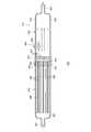
図1は、第1の実施の形態に係る流体殺菌装置10の構成を概略的に示す図である。流体殺菌装置10は、長手方向に延びる流路13を区画する筐体12と、フィルタ40と、光源50と、を備える。流体殺菌装置10は、フィルタ40を通過して層流状態で流れる流体に光源50からの紫外光を照射し、流路13を流れる水などの流体に殺菌処理を施す。
(First Embodiment)
FIG. 1 is a diagram schematically illustrating a configuration of a
筐体12は、第1筐体20と、第2筐体30とを含む。第1筐体20は、流入端21と第1接続端22を有し、流入端21から第1接続端22に長手方向に延びて第1流路23を区画する直管状の部材である。第2筐体30は、流出端31と第2接続端32を有し、第2接続端32から流出端31に長手方向に延びて第2流路33を区画する直管状の部材である。第1接続端22の外周および第2接続端32の内周にはねじ切り(不図示)が施されており、第1接続端22と第2接続端32が螺合して第1筐体20と第2筐体30が接続される。
The
第1筐体20および第2筐体30は、流入端21から流出端31に長手方向に延びる流路13を形成する。流路13を流れる流体は、流入端21から軸方向に流入して流出端31から軸方向に流出する。本明細書において、流路13に沿った方向を長手方向または軸方向といい、軸方向と直交する方向を径方向ということがある。また、軸方向の相対的な位置関係を示すために、流入端21に近い位置を上流側といい、流出端31に近い位置を下流側ということがある。
The
第1筐体20は、支持構造26を有する。支持構造26は、第1筐体20の中心軸付近を長手方向に延びる管状部材である。支持構造26の先端部29は、第1接続端22の近傍に位置し、先端部29に光源50が取り付けられる。支持構造26は、流入端21の近傍の位置において径方向に屈曲し、第1筐体20の壁面に設けられる配線孔28と接続する。支持構造26の内側には、光源50に電力を供給するための配線58が設けられる。
The
第1筐体20および第2筐体30は、金属材料や樹脂材料で構成される。第2筐体30は、紫外光の反射率が高い材料で構成されることが望ましく、例えば、鏡面研磨されたアルミニウム(Al)や、全フッ素化樹脂であるポリテトラフルオロエチレン(PTFE)で構成される。特に、紫外高反射率の高い材料で第2筐体30の内壁面30aを構成することで、光源50が発する紫外光を内壁面30aで反射させて第2流路33を流れる流体に再度照射できる。PTFEは、化学的に安定した材料であり、紫外光の反射率が高い材料であるため、第2筐体30の材料として好適である。なお、第1筐体20をアルミニウムやPTFEで構成してもよい。
The
フィルタ40は、第1筐体20の内部に設けられる。フィルタ40は、いわゆる中空糸フィルタであり、第1流路23の軸方向に延びる複数の中空糸42を有する。複数の中空糸42は、それぞれの両端部44が第1接続端22の位置に揃うように半分に折り曲げられて束状となっている。複数の中空糸42は、第1接続端22を充填するシーラント46により両端部44が固定され、シーラント46の下流側端面において両端部44の開口が露出している。複数の中空糸42は、軸方向に長く設けられることが望ましく、図示されるように、第1流路23の長さのほぼ全体にわたって設けられることが好ましい。
The
光源50は、発光素子52と、封止窓54と、リフレクタ56とを有する。光源50は、第2流路33を流れる流体に向けて紫外光を照射する。光源50は、支持構造26の先端部29に取り付けられており、径方向の位置が流路13の中心軸上または中心軸付近となるように配置される。また、光源50は、軸方向の位置が第1筐体20と第2筐体30の境界部付近またはフィルタ40の出口付近に配置される。
The
発光素子52は、紫外光を発するLED(Light Emitting Diode)であり、その中心波長またはピーク波長が約200nm〜350nmの範囲に含まれる。発光素子52は、殺菌効率の高い波長である260nm〜270nm付近の紫外光を発することが好ましい。このような紫外光LEDとして、例えば、窒化アルミニウムガリウム(AlGaN)を用いたものが知られている。
The
封止窓54は、発光素子52を封止して発光素子52を保護する。封止窓54は、紫外光透過率の高い材料で構成されることが望ましく、石英(SiO2)やサファイア(Al2O3)、非晶質のフッ素系樹脂などで構成される。封止窓54は、例えば、図示されるような砲弾型の形状を有し、フィルタ40の出口から流出する流体の流れを阻害しないような流線形状を有することが好ましい。封止窓54は、発光素子52からの紫外光の配光特性を調整するようなレンズ機能を有する形状を有してもよい。
The sealing
リフレクタ56は、発光素子52からの紫外光の一部を反射させて紫外光の向きを調整する。リフレクタ56は、発光素子52の囲むように設けられており、発光素子52からフィルタ40に向かう紫外光を第2流路33の下流側に向けて反射させる。リフレクタ56は、アルミニウムやPTFEなどの紫外光反射率の高い材料で構成される。リフレクタ56は、発光素子52とともに封止窓54によって封止されている。
The
以上の構成により、流体殺菌装置10は、第2流路33を流れる流体に紫外光を照射して流体に殺菌処理を施す。流入端21から流入する流体は、中空糸42で構成されるフィルタ40を通過する。つまり、流体は、中空糸42の外部空間から内部空間に移動して濾過されて両端部44の開口から流出する。フィルタ40は、流体に含まれる微粒子等のゴミを除去するとともに、軸方向に延びる複数の中空糸42によって第1流路23における流体の流れを整えて層流化させる。流体は、フィルタ40の出口からは層流状態となって流出し、層流状態のまま第2流路33を流れる。光源50は、層流状態の流体に向けて軸方向に紫外光を照射する。紫外光が照射された流体は、流出端31から流出する。
With the above configuration, the
本実施の形態によれば、長手方向に延びるフィルタ40によって層流化された流体に紫外光を照射するため、乱流状態の流体に紫外光を照射する場合と比べて殺菌効率を高めることができる。本発明者らの知見により、直線状の流路内に紫外光を照射して殺菌処理をする場合、乱流状態とするよりも層流状態とする方が5倍〜7倍程度の殺菌効率が得られることがわかっている。乱流状態の場合には、流体に均一に紫外光を照射できず、十分な照射エネルギーを与えないまま流体の一部が流出してしまう。その結果、十分な殺菌処理が施されていない流体の一部が流出して殺菌効率を低下させてしまう。一方、本実施の形態によれば、フィルタ40によって層流化した流体に紫外光を照射できるため、流体全体に所定以上のエネルギー量の紫外光を照射して殺菌効果を高めることができる。
According to the present embodiment, since the fluid that has been laminarized by the
本実施の形態によれば、フィルタ40の出口付近に光源50を配置し、フィルタ40と反対側に紫外光を照射する構成としているため、フィルタ40を構成する中空糸42やシーラント46に紫外光が照射されにくい。一般に、中空糸42はポリスルホンやポリエーテルスルホン等の高分子樹脂、シーラント46はウレタン樹脂等で形成され、いずれも有機系材料で構成されるため、紫外光の照射によって劣化するおそれがある。本実施の形態によれば、中空糸42やシーラント46に紫外光が照射されにくい構造としているため、中空糸42やシーラント46の劣化を防ぐことができ、流体殺菌装置10の耐久性や信頼性を高めることができる。
According to the present embodiment, since the
本実施の形態によれば、筐体12が第1筐体20と第2筐体30により構成されるとともに、第1筐体20と第2筐体30が着脱可能に接続されているため、筐体12の内部をメンテナンスしやすい。例えば、フィルタ40の交換が必要な場合には、第1筐体20と第2筐体30を分離してフィルタ40を取り外すことができ、新しいフィルタ40を容易に付けることができる。また、筐体12を分解して内部を清掃することも容易である。したがって、本実施の形態によれば、流体殺菌装置10の利便性を高めることができる。
According to the present embodiment, the
(第2の実施の形態)
図2は、第2の実施の形態に係る流体殺菌装置110の構成を概略的に示す断面図である。流体殺菌装置110は、第1筐体120の流入端121に、軸方向と交差または直交する方向に延びる流入管124が設けられる点で上述の第1の実施の形態と相違する。以下、流体殺菌装置110について第1の実施の形態との相違点を中心に説明する。
(Second embodiment)
FIG. 2 is a cross-sectional view schematically illustrating a configuration of a
流体殺菌装置110は、流路113を区画する筐体112と、フィルタ140と、光源50とを備える。筐体112は、第1筐体120と、第2筐体30とを含む。
The
第1筐体120は、流入端121と、第1接続端122と、流入管124と、キャップ125と、支持構造126とを有する。第1筐体120は、流入端121から第1接続端122に長手方向に延びて第1流路123を区画する。流入端121には、流入端121の開口を塞ぐキャップ125と、流入端121から径方向に延びる流入管124とが設けられる。流入管124から径方向に流入する流体は、流入端121において向きを変えて第1接続端122に向けて軸方向に流れる。第1接続端122には、第2筐体30の第2接続端32が接続される。第2筐体30は、第1の実施の形態と同様に構成される。
The
支持構造126は、第1筐体120の中心軸付近に設けられる。支持構造126は、キャップ125の中央付近に設けられる配線孔128から軸方向に延びており、第1接続端122に位置する先端部129に光源50が取り付けられる。支持構造126の内部には、配線58が挿通されている。光源50は、第1の実施の形態と同様に構成される。
The
フィルタ140は、複数の中空糸142と、第1シーラント145と、第2シーラント146とを有する。複数の中空糸142は、各第1端部143が流入端121の位置で揃うとともに、各第2端部144が第1接続端122の位置で揃うように束ねられている。第1端部143は、第1シーラント145によって流入端121およびキャップ125に固定され、開口が塞がれている。第2端部144は、第2シーラント146によって第1接続端122に固定され、下流側端面において開口が露出している。
The
以上の構成により、流体殺菌装置110は、流入管124から流入する流体をフィルタ140で濾過するとともに、フィルタ140によって層流状態の流れを作り出す。光源50は、フィルタ140の出口から層流状態で流れ出す流体に向けて第2流路33の流れの方向に紫外光を照射する。紫外光により殺菌処理が施された流体は、流出端31から流出する。したがって、本実施の形態においても、上述の第1の実施の形態と同様の効果を得ることができる。
With the above configuration, the
(第3の実施の形態)
図3は、第3の実施の形態に係る流体殺菌装置210の構成を概略的に示す断面図である。流体殺菌装置210は、筐体212として第1筐体220、第2筐体230および第3筐体260を含み、第3筐体260に光源250が取り付けられる点で上述の実施の形態と相違する。以下、流体殺菌装置210について上述の実施の形態との相違点を中心に説明する。
(Third embodiment)
FIG. 3 is a sectional view schematically showing a configuration of a
流体殺菌装置210は、流路213を区画する筐体212と、フィルタ240と、光源250とを備える。筐体212は、第1筐体220と、第2筐体230と、第3筐体260とを含む。
The
第1筐体220は、流入端221と、第1接続端222とを有し、流入端221から第1接続端222に長手方向に延びる第1流路223を形成する。第1接続端222は、第3筐体260の第3接続端261と接続される。第1筐体220の内部にはフィルタ240が設けられる。フィルタ240は、複数の中空糸242を有し、第1の実施の形態に係るフィルタ40と同様に構成される。複数の中空糸242は、軸方向に長く設けられ、両端部244がシーラント246によって第1接続端222に固定される。
The
第2筐体230は、流出端231と、第2接続端232とを有し、第2接続端232から流出端231に長手方向に延びる第2流路233を形成する。第2接続端232は、第3筐体260の第4接続端262に接続される。
The
第3筐体260は、第1筐体220と第2筐体230の間に接続されており、第1流路223と第2流路233をつなぐ第3流路263を区画する。第3筐体260は、第3接続端261と、第4接続端262と、支持構造264とを含む。支持構造264は、第3筐体260の側壁から光源250に向けて延びる梁部265と、光源250が取り付けられる基部266とを有する。梁部265には、光源250の配線258を挿通させるための配線孔267が設けられる。
The
図4(a)、(b)は、支持構造264の構成を模式的に示す断面図である。図4(a)は、図3のA−A線断面を示し、図4(b)は、図4(a)のB−B線断面を示す。支持構造264は、第1梁部265aと、第2梁部265bと、第3梁部265cと、基部266を有する。複数の梁部265a〜265cのそれぞれは、第3筐体260の側壁の異なる位置から第3流路263の中心付近に位置する基部266に向けて径方向に延びる。複数の梁部265a〜265cは、図4(b)に示すように、流体の流れの方向zに沿った断面が流線形となる形状を有する。基部266は、図3に示すように、軸方向に沿った断面が流線形となる形状を有する。
FIGS. 4A and 4B are cross-sectional views schematically showing the configuration of the
光源250は、紫外光を発する発光素子252と、封止窓254とを有する。光源250は、基部266に取り付けられ、第3流路263の中心軸付近に配置される。光源250は、第2流路233を流れる流体向けて軸方向に紫外光を照射する。
The
以上の構成により、流体殺菌装置210は、第1流路223を通過してフィルタ240により層流状態となって第2流路233を流れる流体に紫外光を照射して流体に殺菌処理を施す。また、光源250を固定するための支持構造264が流線形状を有しているため、フィルタ240によって層流化された流体の流れを阻害せずに層流状態のまま第2流路233を流体が流れるようにできる。したがって、本実施の形態においても、上述の実施の形態と同様の効果を得ることができる。
With the above configuration, the
また、本実施の形態によれば、光源250が第1筐体220に設けられず、第1筐体220と分離可能な第3筐体260に設けられるため、フィルタ240を含む第1筐体220の構造をシンプルにできる。また、フィルタ240を交換するためのメンテナンス作業をより簡略化できる。流体殺菌装置210のユーザは、例えば、第3筐体260から第1筐体220を取り外してフィルタ240の交換ができ、または、フィルタ240を含む第1筐体220の全体を取り替えてフィルタ240の交換もできる。これにより、流体殺菌装置210の利便性を高めることができる。
Further, according to the present embodiment, since
(第4の実施の形態)
図5は、第4の実施の形態に係る流体殺菌装置310の構成を概略的に示す断面図である。流体殺菌装置310は、光源350が第2筐体330の流出端331に設けられている点で上述の実施の形態と相違する。以下、流体殺菌装置310について上述の実施の形態との相違点を中心に説明する。
(Fourth embodiment)
FIG. 5 is a cross-sectional view schematically illustrating a configuration of a
流体殺菌装置310は、流路313を区画する筐体312と、フィルタ340と、光源350と、整流板370と、を備える。筐体312は、第1筐体320と、第2筐体330とを含む。
The
第1筐体320は、上述の第1筐体220と同様に構成される。第1筐体320は、流入端321と、第1接続端322とを有し、流入端321から第1接続端322に長手方向に延びる第1流路323を形成する。第1筐体320の内部にはフィルタ340が設けられる。フィルタ340は、軸方向に長く延びる複数の中空糸342を有する。複数の中空糸342は、両端部344がシーラント346によって第1接続端322に固定されている。
The
第2筐体330は、流出端331と、第2接続端332と、流出管334と、端面壁335とを有する。第2筐体330は、第2接続端332から流出端331に長手方向に延びて第2流路333を区画する。流出端331には、第2流路333の軸方向と直交する端面壁335と、流出端331から径方向に延びる流出管334とが設けられる。第2流路333を軸方向に流れる流体は、流出端331において向きを変え、流出管334を通って径方向に流出する。
The
光源350は、発光素子352と、封止窓354とを有し、流路313の末端となる流出端331に設けられる。発光素子352は、端面壁335の中央付近に取り付けられ、第2流路333に向けて紫外光を発する。封止窓354は、発光素子352と第2流路333の間を隔てる板状部材であり、石英(SiO2)やサファイア(Al2O3)、非晶質のフッ素系樹脂などで構成される。封止窓354は、発光素子352からの紫外光を透過させる一方、第2流路333を流れる流体が発光素子352に触れないようにする。
The
整流板370は、第2接続端332に設けられる。整流板370は、複数の通水孔372を有し、フィルタ340の出口から流出する流体の流れを整えて層流化する。整流板370は、紫外光を反射する材料で構成され、例えば、アルミニウムやPTFEで構成される。整流板370は、光源350からの紫外光を反射させて第2流路333の下流側に向かわせるとともに、光源350からの紫外光がフィルタ340を構成する中空糸342やシーラント346に照射されないように紫外光を遮蔽する。整流板370は、複数の通水孔372を通じて紫外光が漏れ出さないように、複数の通水孔372の口径よりも整流板370の軸方向の厚さが大きくなるように構成されることが好ましい。
The
以上の構成により、流体殺菌装置310は、第2流路333を流れる流体に紫外光を照射して殺菌処理を施す。流入端321から流入する流体は、フィルタ340および整流板370を通過して層流化され、層流状態となって第2流路333を流れる流体に紫外光が照射される。光源350は、第2流路333における流体の流れの方向に紫外光を照射する。本実施の形態においても、上述の実施の形態と同様の効果を得ることができる。
With the above configuration, the
また、本実施の形態によれば、光源350が第1筐体320ではなく第2筐体330に設けられるため、上述の第3の実施の形態と同様、フィルタ340を容易に交換することができる。また、フィルタ340の出口付近に整流板370を設けることで、光源350からフィルタ340に向かう紫外光を遮蔽し、紫外光からフィルタ340を保護することができる。これにより、流体殺菌装置310の耐久性および信頼性を高めることができる。
Further, according to the present embodiment, since the
(第5の実施の形態)
図6は、第5の実施の形態に係る流体殺菌装置410の構成を概略的に示す断面図である。流体殺菌装置410は、第2筐体430の側壁に光源450が設けられる点で上述の実施の形態と相違する。以下、流体殺菌装置410について上述の実施の形態との相違点を中心に説明する。
(Fifth embodiment)
FIG. 6 is a cross-sectional view schematically illustrating a configuration of a
流体殺菌装置410は、流路413を区画する筐体412と、フィルタ340と、光源450と、を備える。筐体412は、第1筐体320と、第2筐体430とを含む。第1筐体320およびフィルタ340は、上述の第4の実施の形態と同様に構成される。
The
第2筐体430は、第2接続端432から流出端431に長手方向に第2流路433を区画する。第2筐体430の側壁には光源450が設けられる。光源450は、紫外光を発光素子452を有し、第2流路433を流れる流体に向けて軸方向と交差する方向に紫外光を照射する。第2接続端432には、整流板470が設けられる。整流板470は、複数の通水孔472を有し、フィルタ340の出口から流出する流体の流れを整えて層流化する。また、整流板470は、光源450からの紫外光を遮蔽してフィルタ340を保護する。
The
以上の構成により、流体殺菌装置410は、第2流路433を流れる流体に紫外光を照射して殺菌処理を施す。流入端321から流入する流体は、流入端321から流入する流体は、フィルタ340および整流板370を通過して層流化され、層流状態となって第2流路333を流れる流体に紫外光が照射される。光源350は、第2流路433における流体の流れと交差する方向に紫外光を照射する。光源350からフィルタ340に向かう紫外光は整流板370により遮蔽される。本実施の形態においても、上述の実施の形態と同様の効果を得ることができる。
With the above configuration, the
以上、本発明を実施の形態にもとづいて説明した。本発明は上記実施の形態に限定されず、種々の設計変更が可能であり、様々な変形例が可能であること、またそうした変形例も本発明の範囲にあることは、当業者に理解されるところである。 The present invention has been described based on the embodiments. It is understood by those skilled in the art that the present invention is not limited to the above-described embodiment, and that various design changes are possible, various modifications are possible, and such modifications are also within the scope of the present invention. Where it is.
上述の実施の形態に係る流体殺菌装置は、流体に紫外光を照射して殺菌処理を施すための装置として説明した。変形例においては、紫外光の照射により流体に含まれる有機物を分解させる浄化処理に本流体殺菌装置を用いてもよい。 The fluid sterilization apparatus according to the above-described embodiment has been described as an apparatus for performing a sterilization process by irradiating a fluid with ultraviolet light. In a modified example, the present fluid sterilization apparatus may be used for a purification treatment for decomposing organic substances contained in a fluid by irradiation with ultraviolet light.
上述の実施の形態では、フィルタとして中空糸を用いる場合を示した。変形例においては、活性炭を用いたフィルタや、砒素などの有害物質を選択的に吸着する特殊フィルタを用いてもよい。また、中空糸フィルタとこれらのフィルタを組み合わせて用いてもよい。 In the above embodiment, the case where the hollow fiber is used as the filter has been described. In a modified example, a filter using activated carbon or a special filter for selectively adsorbing harmful substances such as arsenic may be used. Moreover, you may use a hollow fiber filter and these filters in combination.
変形例においては、筐体の内部に水力発電ユニットを設け、流体の流れを利用して発電される電力を用いて光源を点灯させてもよい。 In a modified example, a hydraulic power generation unit may be provided inside the housing, and the light source may be turned on using electric power generated using the flow of the fluid.
10…流体殺菌装置、12…筐体、13…流路、26…支持構造、40…フィルタ、50…光源、52…発光素子、110…流体殺菌装置、112…筐体、113…流路、126…支持構造、140…フィルタ、210…流体殺菌装置、212…筐体、213…流路、240…フィルタ、250…光源、252…発光素子、264…支持構造、310…流体殺菌装置、312…筐体、313…流路、340…フィルタ、350…光源、352…発光素子、370…整流板、410…流体殺菌装置、412…筐体、413…流路、450…光源、452…発光素子、470…整流板。 Reference Signs List 10: fluid sterilizer, 12: housing, 13: flow path, 26: support structure, 40: filter, 50: light source, 52: light emitting element, 110: fluid sterilizer, 112: housing, 113: flow path, 126: Support structure, 140: Filter, 210: Fluid sterilizer, 212: Housing, 213: Flow path, 240: Filter, 250: Light source, 252: Light emitting element, 264: Support structure, 310: Fluid sterilizer, 312 ... Case, 313 ... Flow path, 340 ... Filter, 350 ... Light source, 352 ... Light emitting element, 370 ... Rectifier plate, 410 ... Fluid sterilizer, 412 ... Case, 413 ... Flow path, 450 ... Light source, 452 ... Light emission Element, 470 ... Rectifier plate.
Claims (6)
前記筐体内の上流側に設けられ、前記長手方向に延在する中空糸膜フィルタと、
紫外光を発するLED(Light Emitting Diode)を有し、前記中空糸膜フィルタの出口付近に設けられ、前記中空糸膜フィルタを通過して前記筐体内の下流側を層流状態で流れる流体に向けて前記中空糸膜フィルタと反対側に前記長手方向に紫外光を照射する光源と、を備えることを特徴とする流体殺菌装置。 A housing that defines a flow path extending in the longitudinal direction;
A hollow fiber membrane filter provided on the upstream side in the housing and extending in the longitudinal direction;
It has an LED (Light Emitting Diode) that emits ultraviolet light, is provided near the outlet of the hollow fiber membrane filter, and is directed toward a fluid that passes through the hollow fiber membrane filter and flows downstream in the housing in a laminar flow state. A light source for irradiating ultraviolet light in the longitudinal direction on the side opposite to the hollow fiber membrane filter.
Priority Applications (7)
| Application Number | Priority Date | Filing Date | Title |
|---|---|---|---|
| JP2015216983A JP6629569B2 (en) | 2015-11-04 | 2015-11-04 | Fluid sterilizer |
| CN201680062588.0A CN108348625A (en) | 2015-11-04 | 2016-09-08 | Fluid sterilizing unit |
| KR1020187013971A KR102125157B1 (en) | 2015-11-04 | 2016-09-08 | Fluid sterilization device |
| EP16861836.1A EP3372252B1 (en) | 2015-11-04 | 2016-09-08 | Fluid sterilization apparatus |
| PCT/JP2016/076423 WO2017077767A1 (en) | 2015-11-04 | 2016-09-08 | Fluid sterilization apparatus |
| TW105131664A TWI696585B (en) | 2015-11-04 | 2016-09-30 | Fluid sterilization device |
| US15/964,914 US20180244543A1 (en) | 2015-11-04 | 2018-04-27 | Fluid sterilization device |
Applications Claiming Priority (1)
| Application Number | Priority Date | Filing Date | Title |
|---|---|---|---|
| JP2015216983A JP6629569B2 (en) | 2015-11-04 | 2015-11-04 | Fluid sterilizer |
Publications (2)
| Publication Number | Publication Date |
|---|---|
| JP2017087104A JP2017087104A (en) | 2017-05-25 |
| JP6629569B2 true JP6629569B2 (en) | 2020-01-15 |
Family
ID=58661807
Family Applications (1)
| Application Number | Title | Priority Date | Filing Date |
|---|---|---|---|
| JP2015216983A Active JP6629569B2 (en) | 2015-11-04 | 2015-11-04 | Fluid sterilizer |
Country Status (7)
| Country | Link |
|---|---|
| US (1) | US20180244543A1 (en) |
| EP (1) | EP3372252B1 (en) |
| JP (1) | JP6629569B2 (en) |
| KR (1) | KR102125157B1 (en) |
| CN (1) | CN108348625A (en) |
| TW (1) | TWI696585B (en) |
| WO (1) | WO2017077767A1 (en) |
Families Citing this family (13)
| Publication number | Priority date | Publication date | Assignee | Title |
|---|---|---|---|---|
| JP6530681B2 (en) * | 2015-09-07 | 2019-06-12 | 日機装株式会社 | Sterilizer |
| JP6559577B2 (en) * | 2016-01-06 | 2019-08-14 | 日機装株式会社 | Fluid sterilization apparatus and fluid sterilization method |
| US11312642B2 (en) | 2017-03-31 | 2022-04-26 | Industrial Technology Research Institute | Fluid sterilizing device |
| JP6863135B2 (en) * | 2017-06-29 | 2021-04-21 | 東芝ライテック株式会社 | Fluid sterilizer |
| TWI660754B (en) * | 2017-08-11 | 2019-06-01 | 信通交通器材股份有限公司 | Microbial sterilization ultraviolet tube and air-conditioning system with microbe sterilization ultraviolet tube |
| US10653808B2 (en) * | 2017-11-10 | 2020-05-19 | Bolb Inc. | Disinfection apparatus having submersible UV light devices |
| JP6978341B2 (en) | 2018-02-20 | 2021-12-08 | スタンレー電気株式会社 | Fluid sterilizer |
| JP6626930B1 (en) * | 2018-07-04 | 2019-12-25 | オルガノ株式会社 | Sampling dispenser and pure water production equipment |
| GB2576346B (en) * | 2018-08-15 | 2022-06-29 | Vws Uk Ltd | Water purifying apparatus and method |
| EP3744691A1 (en) * | 2019-05-28 | 2020-12-02 | Watersprint AB | Device for purifying a fluid with uv-light |
| CN114173830B (en) * | 2019-07-31 | 2023-05-26 | 旭化成株式会社 | Ultraviolet irradiation device and ultraviolet irradiation method |
| US11365134B2 (en) | 2019-07-31 | 2022-06-21 | Access Business Group International Llc | Water treatment system |
| KR102276303B1 (en) * | 2020-02-11 | 2021-07-12 | (주)포인트엔지니어링 | Uv sterilizer |
Family Cites Families (16)
| Publication number | Priority date | Publication date | Assignee | Title |
|---|---|---|---|---|
| JPS6095997U (en) * | 1983-12-06 | 1985-06-29 | 神鋼フアウドラー株式会社 | Filtration device with secondary side pollution prevention |
| JPH077967Y2 (en) * | 1990-09-21 | 1995-03-01 | 中野 浩二 | UV irradiation device |
| JP3045089U (en) * | 1997-07-05 | 1998-01-23 | 東洋紡エンジニアリング株式会社 | Sterile water treatment manufacturing equipment |
| JPH11290656A (en) * | 1998-04-10 | 1999-10-26 | Matsushita Electric Ind Co Ltd | Hollow pipe and purification apparatus |
| JPH11309202A (en) * | 1998-04-28 | 1999-11-09 | Hitachi Ltd | Illuminant for photocatalyst |
| JP3900460B2 (en) * | 2000-06-02 | 2007-04-04 | バブコック日立株式会社 | Water treatment equipment |
| CN2625381Y (en) * | 2003-01-17 | 2004-07-14 | 鸿亮国际贸易有限公司 | Hollow fibrous film system filter |
| JP2004223000A (en) * | 2003-01-23 | 2004-08-12 | Iwasaki Kankyo Shisetsu Kk | Polluted air treatment apparatus |
| US9592102B2 (en) * | 2009-05-18 | 2017-03-14 | Kavo Dental Technologies, Llc | Dental hand tool with disinfection reactor |
| JP5374697B2 (en) | 2009-07-09 | 2013-12-25 | ユーヴィックス株式会社 | UV sterilization water purifier and UV LED unit used for it |
| EP2284127A1 (en) * | 2009-08-13 | 2011-02-16 | Koninklijke Philips Electronics N.V. | Device comprising a source for emitting ultraviolet light |
| WO2012043679A1 (en) * | 2010-09-29 | 2012-04-05 | 旭化成ケミカルズ株式会社 | Hollow fiber membrane module, and filtration method and ultrapure water production system using same |
| KR20120074535A (en) * | 2010-12-28 | 2012-07-06 | 현대중공업 주식회사 | Fiber filter module with sterilization means |
| CN102260003A (en) * | 2011-05-31 | 2011-11-30 | 武汉纺织大学 | Microwave electrodeless ultraviolet photocatalysis-double membrane separation coupled treatment device for industrial wastewater |
| JP2014233712A (en) * | 2013-06-05 | 2014-12-15 | Ckd株式会社 | Ultraviolet sterilization device |
| CN203694182U (en) * | 2013-09-27 | 2014-07-09 | 何志明 | Ultraviolet sterilization equipment |
-
2015
- 2015-11-04 JP JP2015216983A patent/JP6629569B2/en active Active
-
2016
- 2016-09-08 EP EP16861836.1A patent/EP3372252B1/en active Active
- 2016-09-08 KR KR1020187013971A patent/KR102125157B1/en active IP Right Grant
- 2016-09-08 WO PCT/JP2016/076423 patent/WO2017077767A1/en active Application Filing
- 2016-09-08 CN CN201680062588.0A patent/CN108348625A/en active Pending
- 2016-09-30 TW TW105131664A patent/TWI696585B/en active
-
2018
- 2018-04-27 US US15/964,914 patent/US20180244543A1/en not_active Abandoned
Also Published As
| Publication number | Publication date |
|---|---|
| JP2017087104A (en) | 2017-05-25 |
| KR102125157B1 (en) | 2020-06-22 |
| US20180244543A1 (en) | 2018-08-30 |
| TWI696585B (en) | 2020-06-21 |
| KR20180069048A (en) | 2018-06-22 |
| CN108348625A (en) | 2018-07-31 |
| WO2017077767A1 (en) | 2017-05-11 |
| TW201718412A (en) | 2017-06-01 |
| EP3372252B1 (en) | 2021-09-22 |
| EP3372252A1 (en) | 2018-09-12 |
| EP3372252A4 (en) | 2019-07-17 |
Similar Documents
| Publication | Publication Date | Title |
|---|---|---|
| JP6629569B2 (en) | Fluid sterilizer | |
| KR102368679B1 (en) | a flowable typed sterilizing device and connector using the same | |
| JP6530681B2 (en) | Sterilizer | |
| WO2015020041A1 (en) | Ultraviolet sterilization device | |
| TWI626958B (en) | Fluid sterilization device and fluid sterilization method | |
| WO2017043355A1 (en) | Sterilization device | |
| KR102505921B1 (en) | a flowable typed sterilizing device and connector using the same | |
| US20190099543A1 (en) | Light irradiation device | |
| JP2019098055A (en) | Fluid sterilizer | |
| JP2018140001A (en) | Fluid sterilizer | |
| JP6021976B2 (en) | UV water treatment equipment | |
| JP2014076422A (en) | Sterilizer | |
| WO2017038764A1 (en) | Sterilization device | |
| JP2017113700A (en) | Fluid sterilizer | |
| JP2014076205A (en) | Sterilizer | |
| JP2018030077A (en) | Sterilization device of flowing water, and sterilization method of flowing water | |
| JP2019162289A (en) | Fluid sterilizing device | |
| RU2461399C2 (en) | Air regeneration cartridge | |
| JP6903551B2 (en) | Fluid processing equipment | |
| JP6637090B2 (en) | Air purification module | |
| JP6236629B2 (en) | UV sterilizer for fluid | |
| JP2020065848A (en) | Sterilizer | |
| JP4382185B2 (en) | Sterilization lamp and liquid supply device | |
| JP2019147114A (en) | Fluid sterilization apparatus | |
| JP2024008165A (en) | Sterilizer |
Legal Events
| Date | Code | Title | Description |
|---|---|---|---|
| A621 | Written request for application examination |
Free format text: JAPANESE INTERMEDIATE CODE: A621 Effective date: 20180522 |
|
| A131 | Notification of reasons for refusal |
Free format text: JAPANESE INTERMEDIATE CODE: A131 Effective date: 20190326 |
|
| A521 | Request for written amendment filed |
Free format text: JAPANESE INTERMEDIATE CODE: A523 Effective date: 20190514 |
|
| A131 | Notification of reasons for refusal |
Free format text: JAPANESE INTERMEDIATE CODE: A131 Effective date: 20191015 |
|
| A521 | Request for written amendment filed |
Free format text: JAPANESE INTERMEDIATE CODE: A523 Effective date: 20191106 |
|
| TRDD | Decision of grant or rejection written | ||
| A01 | Written decision to grant a patent or to grant a registration (utility model) |
Free format text: JAPANESE INTERMEDIATE CODE: A01 Effective date: 20191126 |
|
| A61 | First payment of annual fees (during grant procedure) |
Free format text: JAPANESE INTERMEDIATE CODE: A61 Effective date: 20191205 |
|
| R150 | Certificate of patent or registration of utility model |
Ref document number: 6629569 Country of ref document: JP Free format text: JAPANESE INTERMEDIATE CODE: R150 |
|
| R250 | Receipt of annual fees |
Free format text: JAPANESE INTERMEDIATE CODE: R250 |
|
| R250 | Receipt of annual fees |
Free format text: JAPANESE INTERMEDIATE CODE: R250 |