JP6629263B2 - Terminal displacement detection method, terminal insertion method, terminal displacement detection device, and terminal insertion device - Google Patents
Terminal displacement detection method, terminal insertion method, terminal displacement detection device, and terminal insertion device Download PDFInfo
- Publication number
- JP6629263B2 JP6629263B2 JP2017111656A JP2017111656A JP6629263B2 JP 6629263 B2 JP6629263 B2 JP 6629263B2 JP 2017111656 A JP2017111656 A JP 2017111656A JP 2017111656 A JP2017111656 A JP 2017111656A JP 6629263 B2 JP6629263 B2 JP 6629263B2
- Authority
- JP
- Japan
- Prior art keywords
- connector terminals
- terminal
- unit
- distance
- holding unit
- Prior art date
- Legal status (The legal status is an assumption and is not a legal conclusion. Google has not performed a legal analysis and makes no representation as to the accuracy of the status listed.)
- Active
Links
- 238000003780 insertion Methods 0.000 title claims description 106
- 230000037431 insertion Effects 0.000 title claims description 106
- 238000006073 displacement reaction Methods 0.000 title claims description 59
- 238000001514 detection method Methods 0.000 title claims description 39
- 238000012966 insertion method Methods 0.000 title claims description 23
- 238000005259 measurement Methods 0.000 claims description 37
- 238000000034 method Methods 0.000 claims description 27
- 230000008569 process Effects 0.000 claims description 10
- 238000002788 crimping Methods 0.000 claims description 6
- 230000000903 blocking effect Effects 0.000 claims 1
- 238000012423 maintenance Methods 0.000 claims 1
- 230000008859 change Effects 0.000 description 62
- 230000004308 accommodation Effects 0.000 description 21
- 238000010586 diagram Methods 0.000 description 10
- 238000009530 blood pressure measurement Methods 0.000 description 9
- 238000012937 correction Methods 0.000 description 6
- 230000007423 decrease Effects 0.000 description 4
- 238000013459 approach Methods 0.000 description 3
- 230000004044 response Effects 0.000 description 3
- 238000009864 tensile test Methods 0.000 description 3
- 238000013461 design Methods 0.000 description 2
- 230000000694 effects Effects 0.000 description 2
- 230000007246 mechanism Effects 0.000 description 2
- 238000012986 modification Methods 0.000 description 2
- 230000004048 modification Effects 0.000 description 2
- 238000005096 rolling process Methods 0.000 description 2
- 238000005452 bending Methods 0.000 description 1
- 230000003247 decreasing effect Effects 0.000 description 1
- 238000010191 image analysis Methods 0.000 description 1
- 238000003384 imaging method Methods 0.000 description 1
- 238000009434 installation Methods 0.000 description 1
- 230000001678 irradiating effect Effects 0.000 description 1
- 230000003287 optical effect Effects 0.000 description 1
Images


Classifications
-
- G—PHYSICS
- G01—MEASURING; TESTING
- G01R—MEASURING ELECTRIC VARIABLES; MEASURING MAGNETIC VARIABLES
- G01R31/00—Arrangements for testing electric properties; Arrangements for locating electric faults; Arrangements for electrical testing characterised by what is being tested not provided for elsewhere
-
- H—ELECTRICITY
- H01—ELECTRIC ELEMENTS
- H01R—ELECTRICALLY-CONDUCTIVE CONNECTIONS; STRUCTURAL ASSOCIATIONS OF A PLURALITY OF MUTUALLY-INSULATED ELECTRICAL CONNECTING ELEMENTS; COUPLING DEVICES; CURRENT COLLECTORS
- H01R43/00—Apparatus or processes specially adapted for manufacturing, assembling, maintaining, or repairing of line connectors or current collectors or for joining electric conductors
- H01R43/20—Apparatus or processes specially adapted for manufacturing, assembling, maintaining, or repairing of line connectors or current collectors or for joining electric conductors for assembling or disassembling contact members with insulating base, case or sleeve
-
- G—PHYSICS
- G01—MEASURING; TESTING
- G01D—MEASURING NOT SPECIALLY ADAPTED FOR A SPECIFIC VARIABLE; ARRANGEMENTS FOR MEASURING TWO OR MORE VARIABLES NOT COVERED IN A SINGLE OTHER SUBCLASS; TARIFF METERING APPARATUS; MEASURING OR TESTING NOT OTHERWISE PROVIDED FOR
- G01D5/00—Mechanical means for transferring the output of a sensing member; Means for converting the output of a sensing member to another variable where the form or nature of the sensing member does not constrain the means for converting; Transducers not specially adapted for a specific variable
- G01D5/26—Mechanical means for transferring the output of a sensing member; Means for converting the output of a sensing member to another variable where the form or nature of the sensing member does not constrain the means for converting; Transducers not specially adapted for a specific variable characterised by optical transfer means, i.e. using infrared, visible, or ultraviolet light
- G01D5/32—Mechanical means for transferring the output of a sensing member; Means for converting the output of a sensing member to another variable where the form or nature of the sensing member does not constrain the means for converting; Transducers not specially adapted for a specific variable characterised by optical transfer means, i.e. using infrared, visible, or ultraviolet light with attenuation or whole or partial obturation of beams of light
- G01D5/34—Mechanical means for transferring the output of a sensing member; Means for converting the output of a sensing member to another variable where the form or nature of the sensing member does not constrain the means for converting; Transducers not specially adapted for a specific variable characterised by optical transfer means, i.e. using infrared, visible, or ultraviolet light with attenuation or whole or partial obturation of beams of light the beams of light being detected by photocells
- G01D5/341—Mechanical means for transferring the output of a sensing member; Means for converting the output of a sensing member to another variable where the form or nature of the sensing member does not constrain the means for converting; Transducers not specially adapted for a specific variable characterised by optical transfer means, i.e. using infrared, visible, or ultraviolet light with attenuation or whole or partial obturation of beams of light the beams of light being detected by photocells controlling the movement of a following part
-
- H—ELECTRICITY
- H01—ELECTRIC ELEMENTS
- H01R—ELECTRICALLY-CONDUCTIVE CONNECTIONS; STRUCTURAL ASSOCIATIONS OF A PLURALITY OF MUTUALLY-INSULATED ELECTRICAL CONNECTING ELEMENTS; COUPLING DEVICES; CURRENT COLLECTORS
- H01R13/00—Details of coupling devices of the kinds covered by groups H01R12/70 or H01R24/00 - H01R33/00
- H01R13/40—Securing contact members in or to a base or case; Insulating of contact members
- H01R13/42—Securing in a demountable manner
- H01R13/422—Securing in resilient one-piece base or case, e.g. by friction; One-piece base or case formed with resilient locking means
- H01R13/4223—Securing in resilient one-piece base or case, e.g. by friction; One-piece base or case formed with resilient locking means comprising integral flexible contact retaining fingers
Description
本発明は、各々が電線の端部に圧着接続された複数のコネクタ端子それぞれの先端相互間のズレ量を求める端子ズレ量検知方法、及び、そのように求めたズレ量に基づいて複数のコネクタ端子の挿入を行う端子挿入方法に関する。また、本発明は、上記の端子ズレ量検知方法に用いられる端子ズレ量検知装置、及び、上記の端子挿入方法に用いられる端子挿入装置に関するものである。 The present invention provides a terminal displacement detection method for determining a displacement between tips of a plurality of connector terminals, each of which is crimped to an end of an electric wire, and a plurality of connectors based on the displacement thus determined. The present invention relates to a terminal insertion method for inserting a terminal. The present invention also relates to a terminal displacement amount detection device used in the above-described terminal displacement amount detection method and a terminal insertion device used in the above-described terminal insertion method.
従来、高周波信号の伝送に、複数の電線をより合わせたツイストケーブルや、ツイスト電線に更にシールドを施したツイストシールドケーブル等が用いられている。そして、このようなケーブルをなす複数の電線それぞれの端部に圧着接続された複数のコネクタ端子をコネクタハウジングにおける複数の端子収容室に挿入する作業がしばしば行われている。このとき、コネクタ端子を1つずつ端子収容室に挿入するためには、コネクタハウジングの近傍におけるコネクタ端子の自由な取り回しのために、ツイストを解したり、シールド部材を除去したりして、個別にばらす電線の余長が長くなる場合がある。このような余長が長くなるとシールド効果が低減する恐れがある。 2. Description of the Related Art Conventionally, a twisted cable in which a plurality of electric wires are twisted or a twisted shielded cable in which a twisted electric wire is further shielded has been used for transmitting a high-frequency signal. An operation of inserting a plurality of connector terminals crimp-connected to respective ends of a plurality of electric wires forming such a cable into a plurality of terminal accommodating chambers of a connector housing is often performed. At this time, in order to insert the connector terminals one by one into the terminal accommodating chamber, the twist or the shield member is removed by untwisting and removing the shield member in order to freely manage the connector terminals near the connector housing. In some cases, the extra length of the wire to be exposed may become longer. If the extra length is long, the shielding effect may be reduced.
そこで、複数のコネクタ端子を、一括して治具に保持し、その状態のまま複数の端子収容室に同時挿入する技術が提案されている(例えば、特許文献1参照。)。この技術によれば、端子収容室への挿入時にコネクタ端子を個別に取回す必要が無いので、上記のような電線の余長を抑えることができる。 Therefore, a technique has been proposed in which a plurality of connector terminals are collectively held by a jig and simultaneously inserted into a plurality of terminal accommodating chambers in that state (for example, see Patent Document 1). According to this technique, it is not necessary to individually arrange the connector terminals when inserting the connector terminals into the terminal accommodating chamber, so that the above-described extra length of the electric wire can be suppressed.
しかしながら、特許文献1の技術では、複数のコネクタ端子の先端相互間にズレが生じた状態で、複数の端子収容室に同時挿入される可能性がある。例えば、何れかのコネクタ端子の先端が、他のコネクタ端子の先端よりも、挿入方向の後方に大きくズレている場合には、そのズレているコネクタ端子の端子収容室への挿入が不十分となる恐れがある。このため、複数のコネクタ端子の先端相互間のズレ量を挿入前に把握することができる技術が求められている。
However, in the technique of
従って、本発明は、上記のような問題に着目し、複数のコネクタ端子について、先端相互間のズレ量を挿入前に把握することができる端子ズレ量検知方法、端子挿入方法、端子ズレ量検知装置、及び端子挿入装置を提供することを目的とする。 Accordingly, the present invention focuses on the above-described problems, and, for a plurality of connector terminals, a terminal displacement amount detection method, a terminal insertion method, and a terminal displacement amount detection method capable of grasping a displacement amount between tips before insertion. It is an object to provide a device and a terminal insertion device.
上記課題を解決するために、本発明の端子ズレ量検知方法は、各々が電線の端部に圧着接続された複数のコネクタ端子を、互いに平行に一列に配列して保持した保持部を、前記複数のコネクタ端子それぞれの先端を進行方向に向けて、前記保持部の移動距離を測定しながら直進移動させる移動工程と、前記複数のコネクタ端子それぞれの進路を当該複数のコネクタ端子の配列方向に見た側面視で互いに一致する、当該進路における目標点の、前記複数のコネクタ端子それぞれの先端の通過を検知する通過検知工程と、前記複数のコネクタ端子それぞれの先端について前記通過が検知されたときの前記移動距離に基づいて、前記複数のコネクタ端子それぞれの先端相互間のズレ量を求めるズレ量取得工程と、を備えることを特徴とする。 In order to solve the above-mentioned problem, the terminal displacement detecting method of the present invention includes a plurality of connector terminals each of which is crimped and connected to an end of an electric wire, wherein the holding unit holds the connector terminals arranged in a line in parallel with each other. A moving step of moving the tip end of each of the plurality of connector terminals in the advancing direction and moving straight while measuring a moving distance of the holding unit; and viewing a path of each of the plurality of connector terminals in an arrangement direction of the plurality of connector terminals. The passage detection step of detecting the passage of the tip of each of the plurality of connector terminals of the target point on the course, and the passage when the passage is detected for the tips of the plurality of connector terminals. A shift amount obtaining step of obtaining a shift amount between the tips of the plurality of connector terminals based on the moving distance.
また、上記課題を解決するために、本発明の端子挿入方法は、各々が電線の端部に圧着接続された複数のコネクタ端子を、互いに平行に一列に配列して保持した保持部を、前記複数のコネクタ端子それぞれの先端を進行方向に向けて、前記保持部の移動距離を測定しながら直進移動させる移動工程と、前記複数のコネクタ端子それぞれの進路を当該複数のコネクタ端子の配列方向に見た側面視で互いに一致する、当該進路における目標点の、前記複数のコネクタ端子それぞれの先端の通過を検知する通過検知工程と、前記複数のコネクタ端子それぞれの先端について前記通過が検知されたときの前記移動距離に基づいて、前記複数のコネクタ端子それぞれの先端相互間のズレ量を求めるズレ量取得工程と、前記ズレ量が所定の閾値未満の場合に、前記保持部を更に直進移動させて、前記複数のコネクタ端子それぞれの前記進路に複数の端子収容室が一対一に位置するように配置されたコネクタハウジングの前記複数の端子収容室に前記複数のコネクタ端子を同時挿入する挿入工程と、を備えることを特徴とする。 Further, in order to solve the above problem, the terminal insertion method of the present invention, the holding portion holding a plurality of connector terminals, each of which is crimped and connected to the end of the electric wire, arranged in a line in parallel with each other, A moving step of moving the tip end of each of the plurality of connector terminals in the advancing direction and moving straight while measuring a moving distance of the holding unit; and viewing a path of each of the plurality of connector terminals in an arrangement direction of the plurality of connector terminals. The passage detection step of detecting the passage of the tip of each of the plurality of connector terminals of the target point on the course, and the passage when the passage is detected for the tips of the plurality of connector terminals. A shift amount obtaining step of obtaining a shift amount between the tips of the plurality of connector terminals based on the moving distance, and when the shift amount is less than a predetermined threshold value Further, the holding portion is further moved straight, and the plurality of terminal accommodating chambers of the connector housing are arranged such that a plurality of terminal accommodating chambers are located one-to-one on the respective paths of the plurality of connector terminals. And an insertion step of simultaneously inserting the connector terminals.
また、上記課題を解決するために、本発明の端子ズレ量検知装置は、各々が電線の端部に圧着接続された複数のコネクタ端子を、互いに平行に一列に配列して保持する保持部と、前記保持部を、前記複数のコネクタ端子それぞれの先端を進行方向に向けて直進移動させる移動部と、前記保持部の前記進行方向への移動距離を測定する距離測定部と、前記複数のコネクタ端子それぞれの進路を当該複数のコネクタ端子の配列方向に見た側面視で互いに一致する、当該進路における目標点の、前記複数のコネクタ端子それぞれの先端の通過を検知する通過検知部と、前記複数のコネクタ端子それぞれの先端について前記通過が検知されたときの前記移動距離に基づいて、前記複数のコネクタ端子それぞれの先端相互間のズレ量を求めるズレ量取得部と、を備えたことを特徴とする。 Further, in order to solve the above problems, the terminal displacement amount detection device of the present invention includes a plurality of connector terminals, each of which is crimped and connected to an end of an electric wire, and a holding unit that holds the plurality of connector terminals arranged in a line in parallel with each other. A moving unit that moves the tip of each of the plurality of connector terminals straight in the traveling direction, a distance measuring unit that measures a moving distance of the retaining unit in the traveling direction, and the plurality of connectors. A passage detection unit that detects passage of a tip of each of the plurality of connector terminals at a target point on the course, wherein paths of the terminals match each other in a side view when viewed in an arrangement direction of the plurality of connector terminals; A displacement amount obtaining a displacement amount between the distal ends of the plurality of connector terminals based on the moving distance when the passage is detected for the distal ends of the respective connector terminals. Characterized by comprising a and.
また、上記課題を解決するために、本発明の端子挿入装置は、各々が電線の端部に圧着接続された複数のコネクタ端子を、互いに平行に一列に配列して保持する保持部と、前記保持部を、前記複数のコネクタ端子それぞれの先端を進行方向に向けて直進移動させる移動部と、前記保持部の前記進行方向への移動距離を測定する距離測定部と、前記複数のコネクタ端子それぞれの進路を当該複数のコネクタ端子の配列方向に見た側面視で互いに一致する、当該進路における目標点の、前記複数のコネクタ端子それぞれの先端の通過を検知する通過検知部と、コネクタハウジングを、前記複数のコネクタ端子それぞれの前記進路に複数の端子収容室が一対一に位置するように保持するハウジング保持部と、前記複数のコネクタ端子それぞれの先端について前記通過が検知されたときの前記移動距離に基づいて、前記複数のコネクタ端子それぞれの先端相互間のズレ量を求めるズレ量取得部と、前記ズレ量が所定の閾値未満であることを表す情報を取得する情報取得部と、前記情報取得部における前記情報の取得を受けて、前記移動部に前記保持部を更に直進移動させて、前記複数の端子収容室に前記複数のコネクタ端子を同時挿入する挿入制御部と、を備えることを特徴とする。 Further, in order to solve the above problems, the terminal insertion device of the present invention, a plurality of connector terminals each crimped connection to the end of the wire, a holding unit that holds and arranged in a row in parallel to each other, A holding unit, a moving unit that moves a tip of each of the plurality of connector terminals in a straight line toward a traveling direction, a distance measuring unit that measures a moving distance of the holding unit in the traveling direction, and each of the plurality of connector terminals. The path is coincident with each other in a side view when viewed in the arrangement direction of the plurality of connector terminals, a target point on the path, a passage detection unit that detects the passage of the tip of each of the plurality of connector terminals, and a connector housing, A housing holding portion for holding a plurality of terminal accommodating chambers on the path of each of the plurality of connector terminals so as to be positioned one-to-one, and a tip of each of the plurality of connector terminals A shift amount obtaining unit that calculates a shift amount between the tips of the plurality of connector terminals based on the movement distance when the passage is detected, and indicates that the shift amount is less than a predetermined threshold. An information acquisition unit that acquires information, and in response to the acquisition of the information by the information acquisition unit, further moves the holding unit straight ahead to the moving unit, and simultaneously connects the plurality of connector terminals to the plurality of terminal accommodating chambers. And an insertion control unit for inserting.
本発明の端子ズレ量検知方法では、複数のコネクタ端子それぞれの先端について上記の目標点の通過が検知されたときの保持部の移動距離に基づいて、複数のコネクタ端子それぞれの先端相互間のズレ量が取得される。具体的には、例えば、各先端について目標点の通過が検知されたときの移動距離の差異を算出すること等でズレ量を求めることができる。このズレ量の取得は、作業者が計算して行ってもよく、あるいは、コンピュータに移動距離の計測結果が入力されるように構成しておき、このコンピュータに自動で計算させてもよい。このように、本発明の端子ズレ量検知方法によれば、複数のコネクタ端子について、先端相互間のズレ量を挿入前に把握することができる。 In the terminal displacement amount detecting method of the present invention, the displacement between the distal ends of the plurality of connector terminals is determined based on the moving distance of the holding portion when the passage of the target point is detected for the distal ends of the plurality of connector terminals. The quantity is obtained. Specifically, for example, the deviation amount can be obtained by calculating the difference in the moving distance when passage of the target point is detected for each tip. The shift amount may be obtained by calculation by an operator, or may be configured so that a measurement result of the moving distance is input to a computer, and the computer may automatically calculate the shift amount. As described above, according to the terminal shift amount detecting method of the present invention, the shift amounts between the tips of a plurality of connector terminals can be grasped before insertion.
また、本発明の端子挿入方法によれば、上述した本発明の端子ズレ量検知方法と同様の手法により、複数のコネクタ端子について、先端相互間のズレ量を挿入前に把握することができる。そして、そのように把握されたズレ量に基づいて、保持部での保持状態を矯正する等して、ズレ量が所定の閾値未満となった場合にコネクタ端子の挿入が行われる。これにより、複数のコネクタ端子を複数の端子収容室に十分に挿入することができる。 Further, according to the terminal insertion method of the present invention, it is possible to grasp the amount of displacement between the tips of a plurality of connector terminals before insertion by using the same method as the above-described method for detecting the amount of terminal displacement of the present invention. The connector terminal is inserted when the amount of deviation is less than a predetermined threshold by correcting the holding state of the holding unit based on the amount of deviation thus grasped. Thereby, the plurality of connector terminals can be sufficiently inserted into the plurality of terminal receiving chambers.
また、本発明の端子ズレ量検知装置によれば、複数のコネクタ端子それぞれの先端について上記の目標点の通過が検知されたときの保持部の移動距離に基づいて、ズレ量取得部において、複数のコネクタ端子それぞれの先端相互間のズレ量が取得される。尚、本発明の端子ズレ量検知装置は、ズレ量取得部に代えて、複数のコネクタ端子それぞれの先端について上記の目標点の通過が検知されたときの保持部の移動距離を出力する出力部をそなえたものであってもよい。この場合には、例えば、作業者は、出力された移動距離の差異を算出すること等でズレ量を求めることができる。何れにしても、本発明の端子ズレ量検知装置によれば、複数のコネクタ端子について、先端相互間のズレ量を挿入前に把握することができる。 Further, according to the terminal shift amount detecting device of the present invention, the shift amount obtaining unit determines a plurality of connector terminals based on the moving distance of the holding unit when the passage of the target point is detected for the tip end of each of the plurality of connector terminals. Of each connector terminal is obtained. Note that the terminal displacement amount detection device of the present invention is an output unit that outputs the moving distance of the holding unit when passage of the above-described target point is detected at the tip of each of the plurality of connector terminals, instead of the displacement amount acquisition unit. May be provided. In this case, for example, the operator can obtain the displacement amount by calculating the difference in the output moving distance. In any case, according to the terminal shift amount detecting device of the present invention, the shift amounts between the distal ends of the plurality of connector terminals can be grasped before insertion.
本発明の端子挿入装置によれば、上述した本発明の端子ズレ量検知装置と同様の手法により、複数のコネクタ端子について、先端相互間のズレ量を挿入前に把握することができる。そして、そのように把握されたズレ量に基づいた保持部での保持状態の矯正等の結果、ズレ量が所定の閾値未満となった旨の情報が取得されると、コネクタ端子の挿入が行われる。これにより、複数のコネクタ端子を複数の端子収容室に十分に挿入することができる。 According to the terminal insertion device of the present invention, it is possible to grasp the amount of displacement between the tips of a plurality of connector terminals before insertion by the same method as the above-described terminal displacement amount detecting device of the present invention. Then, as a result of correction of the holding state in the holding unit based on the amount of misalignment thus obtained, if information indicating that the amount of misalignment has become less than the predetermined threshold is obtained, insertion of the connector terminal is performed. Be done. Thereby, the plurality of connector terminals can be sufficiently inserted into the plurality of terminal receiving chambers.
以下、端子ズレ量検知方法、端子挿入方法、端子ズレ量検知装置、及び端子挿入装置の一実施形態について説明する。 Hereinafter, an embodiment of a terminal displacement amount detection method, a terminal insertion method, a terminal displacement amount detection device, and a terminal insertion device will be described.
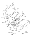
図1は、本発明の一実施形態にかかる端子挿入装置を示す図である。 FIG. 1 is a diagram showing a terminal insertion device according to one embodiment of the present invention.
図1に示されている端挿入装置1は、2芯のツイストケーブル5における2本の電線51それぞれの端部に圧着接続された2個のコネクタ端子52を、コネクタハウジング6における2つの端子収容室61に同時挿入する装置である。この端子挿入装置1は、保持部11と、移動部12と、距離測定部13と、通過検知部14と、出力部15と、ハウジング保持部16と、電線色検知部17と、制御部18と、入力部19と、圧力測定部20と、を備えている。
The
保持部11は、各々が電線51の端部に圧着接続された2個のコネクタ端子52を、互いに平行に一列に配列して保持する。そして、移動部12が、保持部11を、2個のコネクタ端子52それぞれの先端を進行方向D11に向けて直進移動させる。この移動部12は、制御部18の制御の下で駆動するモータと、そのモータの回転駆動力を保持部11の直進駆動力に変換する機構部とで構成されている。本実施形態では、入力部19に対する作業者による操作を受けて、制御部18が、移動部12に保持部11の直進移動を開始させる(移動工程)。直進移動の停止は、制御部18の後述の判断により行われる。
The holding
図2は、図1に示されている保持部を示す図である。 FIG. 2 is a diagram illustrating the holding unit illustrated in FIG. 1.
この図2に示されているように、保持部11は、各々が矩形板形状に形成された2枚の保持板111が、各々の一辺でヒンジ結合されたものである。各保持板111には、ツイストケーブル5における2個のコネクタ端子52の側が嵌め込まれる保持溝111aが形成されている。この保持溝111aには、コネクタ端子52、電線51、及びツイストケーブル5における最外被覆部分53が嵌め込まれる。この状態で、一方の保持板111が矢印D12方向に閉じられると、2個のコネクタ端子52が、配列方向D13に、互いに平行に一列に配列された状態で保持される。
As shown in FIG. 2, the holding
このとき、本実施形態では、保持部111には、2個のコネクタ端子52それぞれにおける電線51との圧着部521を、この圧着部521の近傍の電線51と共に挟持する挟持部111bが設けられている。この挟持部111bは、2個のコネクタ端子52それぞれにおける圧着部521及びその近傍の電線51を、直進方向D11に沿った各コネクタ端子52の進路522及び、コネクタ端子52の配列方向D13の双方と交差する方向D14から挟持する。これにより、保持部111は、コネクタ端子52のローリング等を抑えて一層安定した姿勢で保持することができる。また、本実施形態では、この挟持部111bが、着脱自在に構成されている。
At this time, in the present embodiment, the holding
図1に示されている距離測定部13は、保持部11に設けられている距離測定用の突起112によって進行方向D11に押されて直進する直進部131と、この直進部131をスライド移動自在に保持する受け部132と、を備えている。本実施形態では、この距離測定部13として、磁気式の検出原理を利用したマグネスケール(登録商標)が採用されている。距離測定部13では、直進部131の移動距離が、保持部11の移動距離として制御部18に出力される。保持部11が直進移動する移動工程の際には、この距離測定部13によって保持部11の移動距離が測定される。
The
通過検知部14は、センサ光14aを発する発光部141と、センサ光14aを受光する受光部142と、を備えている。
The
図3は、図1に示されている通過検知部を示す図である。 FIG. 3 is a diagram showing the passage detection unit shown in FIG.
この図3に示されているように、通過検知部14では、各コネクタ端子52の進路522における目標点522aを通るように、発光部141と受光部142とが2セット配置されている。ここで、各進路522における目標点522aは、2本の進路522を2個のコネクタ端子52の配列方向D13に見た側面視で互いに一致する、当該進路522における点である。各セットの発光部141を発したセンサ光14aは、目標点522aを通過して受光部142で受光されている。
As shown in FIG. 3, in the
保持部11が、2個のコネクタ端子52それぞれの先端を進行方向D11に向けて直進移動し、やがて各コネクタ端子52の先端が各目標点522aに達すると、その先端によってセンサ光14aが遮られる。通過検知部14では、各セットにおける受光部141でセンサ光14aが受光状態から非受光状態となったことを以て対応するコネクタ端子52の先端の目標点522aの通過を検知する(通過検知工程)。検知結果は、図1に示されている制御部18に送られる。
The holding
他方、距離測定部13では、2個のコネクタ端子52を保持した保持部11の進行方向D11への移動距離が測定されて制御部18に送られている。本実施形態では、2個のコネクタ端子52それぞれの先端について、目標点522aの通過が通過検知部14で検知されたときの距離測定部13での測定結果が、制御部18での制御の下で、出力部15によって出力される。本実施形態では、出力部15が表示画面を有しており、この出力部15によって距離測定部13での測定結果が出力表示される。また、制御部18は、2個のコネクタ端子52の全てについて先端の目標点522aの通過が検知されたタイミングで、移動部12による保持部11の直進移動を停止させる。
On the other hand, the
本実施形態では、制御部18によって、2個のコネクタ端子52それぞれについての測定結果(移動距離)に基づいて、2個のコネクタ端子52それぞれの先端相互間のズレ量g11が求められる。このズレ量g11は、各先端について目標点522aの通過が検知されたときの移動距離の差異を算出することで求められる(ズレ量取得工程)。算出結果としてのズレ量g11は、制御部18での制御の下で、出力部15に出力表示される。このように、制御部18は、2個のコネクタ端子52それぞれの先端について目標点522aの通過が検知されたときの移動距離に基づいて、2個のコネクタ端子52それぞれの先端相互間のズレ量を求めるズレ量取得部の一例に相当する。
In the present embodiment, the
また、本実施形態の端子挿入装置1には、電線色検知部17が設けられており、2個のコネクタ端子52それぞれが圧着接続されている電線51の色が検知される。検知結果は制御部18に送られ、この制御部18の制御の下、出力部15は、距離測定部13での測定結果を、対応する電線51の色とともに出力表示する。これにより、作業者は、2個のコネクタ端子52のうち、何れの色の電線51に圧着接続されているコネクタ端子52が、進行方向D11の前方側にズレているかを判断することができる。
Further, the
以上に説明した、保持部11の移動工程、各コネクタ端子52の先端の目標点522aの通過検知工程、及びズレ量g11を求めるズレ量取得工程、からなる一連の作業が、端子ズレ量検知方法の一例に相当する。また、本実施形態の端子挿入装置1において、保持部11、移動部12、距離測定部13、通過検知部14、出力部15、電線色検知部17、制御部18、及び入力部19の組合せが、端子ズレ量検知装置の一例に相当する。
The above-described series of operations including the step of moving the holding
本実施形態では、上記のようなズレ量g11の取得に続いて、制御部18が、ズレ量g11を、所定の閾値と比較することで、そのズレ量g11が許容できるか否かを判断する。このように、本実施形態では、制御部18は、上記の判断により、ズレ量g11が閾値未満であることを表す情報I11を自己取得する情報取得部の一例にも相当している。
In the present embodiment, following the acquisition of the displacement amount g11 as described above, the
そして、ズレ量g11が閾値を上回っていた場合には、移動部12を逆向きに動作させて、保持部11を進行方向D11の後方側の初期位置に下げる。
When the displacement amount g11 exceeds the threshold value, the moving
作業者は、保持部11が初期位置に下がると、進行方向D11の前方側にズレているコネクタ端子52を後方側に下げるといった保持部11での矯正作業を行う。その矯正作業の後、再度、入力部19を操作して、保持部11を進行方向D11に直進移動させる。この直進移動において、上述したズレ量の取得と閾値との比較が制御部18によって行われる。このような一連の作業が、ズレ量g11が閾値未満になるまで繰り返される。
When the holding
そして、ズレ量g11が閾値未満になると、制御部18の制御の下で、引き続いてコネクタ端子52の、コネクタハウジング6の端子収容室61への挿入が行われる。
Then, when the deviation amount g11 becomes less than the threshold value, the insertion of the
図1に示されている端子挿入装置1では、コネクタハウジング6を保持するハウジング保持部16が設けられている。ハウジング保持部16は、コネクタハウジング6を、2個のコネクタ端子52それぞれの進路522に2つの端子収容室61が一対一に位置するように保持する。そして、本実施形態では、ハウジング保持部16における各端子収容室61への挿入口16aの近傍に上述した通過検知部14が配置されている。このため、上記のように保持部11の直進移動が繰り返されてズレ量g11が閾値未満になった段階では、2個のコネクタ端子52の先端が、ハウジング保持部16における各端子収容室61への挿入口16aの近傍に位置することとなる。
In the
コネクタ端子52の、コネクタハウジング6の端子収容室61への挿入(挿入工程)は、この状態で、制御部18が引き続いて移動部12を制御して、保持部11を、進行方向D11に更に直進移動させることで行われる。この直進移動により、2つの端子収容室61に2個のコネクタ端子52が同時挿入される。このように、本実施形態では、制御部18は、ズレ量g11が閾値未満であることを表す情報I11の取得を受けて、移動部12に保持部11を更に直進移動させて、2つの端子収容室61に2個のコネクタ端子52を同時挿入する挿入制御部の一例にも相当している。
In the insertion of the
図4は、図1に示されている端子挿入装置で行われるコネクタ端子の挿入工程を示す図である。 FIG. 4 is a view showing a connector terminal insertion process performed by the terminal insertion device shown in FIG.
この挿入工程の初期段階(ステップS11)では、上述したように、2個のコネクタ端子52の先端が、ハウジング保持部16におけるコネクタハウジング6の各端子収容室61への挿入口16aの近傍に位置する。即ち、2個のコネクタ端子52のうち、先行するコネクタ端子52の先端が目標点522aよりも、上記の閾値未満のズレ量だけ進行方向D11の前方に位置している。そして、後続のコネクタ端子52の先端が目標点522aに位置している。保持部11は、制御部18の制御によって、2個のコネクタ端子52の先端のそれぞれがこのように位置した状態で停止している。ステップS11では、制御部18において上記の情報I11が自己取得されると、まず、制御部18が、このときの距離測定部13の測定結果をゼロにセットする。そして、この制御部18の制御の下、保持部11が、進行方向D11更に直進移動する。このとき、保持部11に設けられている距離測定用の突起112によって、距離測定部13の直進部131が進行方向D11に押されて保持部11の移動距離が測定される。このときの測定結果は、上記のように制御部に18によるゼロへのセット以降の保持部11の移動距離になる。この測定結果が制御部18に送られる。
In the initial stage of this insertion process (step S11), as described above, the tips of the two
更に保持部11が進行方向D11に直進移動すると、距離測定部13によって移動距離が測定されつつ2個のコネクタ端子52がコネクタハウジング6の2つの端子収容室61に同時に進入する(ステップS12)。本実施形態では、このステップS12での直進移動は、保持部11における進行方向D11の前方側に位置する上述の挟持部111bがハウジング保持部16に近接するまで行われる。挟持部111bが近接するまでの保持部11の移動距離は予め算出されている。この移動距離は、2個のコネクタ端子52それぞれの先端が両方とも上記の目標点522aに位置すると仮定した場合の保持部11の位置から、挟持部111bが近接するまでの移動距離である。制御部18は、距離測定部13での測定結果が、この予め算出された移動距離に達すると保持部11の移動を停止させる。保持部11が停止すると、作業者は、着脱自在に構成されている挟持部111bを保持部11から取り外す。その後、入力部19を操作して、保持部11の移動を再開させる。
When the holding
挟持部111bが取り外された後の保持部11の直進移動は、距離測定部13での測定結果が、予め求めておいた、2個のコネクタ端子52の全てを2つの端子収容室61に挿入するに足る挿入完了距離に達するまで、制御部18での制御の下で行われる。挿入完了距離は、各々の先端が目標点522aに位置する2個のコネクタ端子52の全てを2つの端子収容室61に挿入するに足る保持部11の移動距離である。そして、測定結果が挿入完了距離に達すると、制御部18は、保持部11の移動を停止させてこの挿入工程を終了させる(ステップS13)。上述したズレ量g11の検知における保持部11の移動工程から、この挿入工程におけるステップS13に至るまでの一連の作業が、端子挿入方法の一例に相当する。
The linear movement of the holding
以上に説明した本実施形態の端子挿入装置1、この端子挿入装置1の一部をなす端子ズレ量検知装置、この端子挿入装置1を用いて行われる端子ズレ量検知方法、及び端子挿入方法によれば、以下のような効果を奏することができる。
The
即ち、本実施形態では、2個のコネクタ端子52それぞれの先端について上記の目標点522aの通過が検知されたときの保持部11の移動距離に基づいて、2個のコネクタ端子52それぞれの先端相互間のズレ量g11が取得される。具体的には、例えば、各先端について目標点522aの通過が検知されたときの移動距離の差異を算出すること等でズレ量g11を求めることができる。このように、本実施形態によれば、2個のコネクタ端子52について、先端相互間のズレ量g11を挿入前に把握することができる。そして、そのように把握されたズレ量g11に基づいた保持部11での保持状態の矯正等の結果、ズレ量g11が所定の閾値未満となった旨の情報I11が取得されると、コネクタ端子52の挿入が行われる。これにより、2個のコネクタ端子52を2つの端子収容室61に十分に挿入することができる。
That is, in the present embodiment, based on the moving distance of the holding
また、本実施形態では、2個のコネクタ端子52それぞれの進路522の目標点522aを各々が通る2本のセンサ光14aを、2個のコネクタ端子52それぞれの先端が遮ったことを以て目標点522aの通過が検知される。このようなセンサ光14aを利用することで、各先端の目標点522aの通過を容易かつ正確に検知することができる。
In the present embodiment, the two
また、本実施形態では、保持部11における挟持部111bが、2個のコネクタ端子52それぞれにおける電線51との圧着部521を挟持する。このように挟持することで、コネクタ端子52のローリング等を抑えて一層安定した姿勢で保持することができる。これにより、各先端の目標点522aの通過を一層正確に検知することができる。
In this embodiment, the holding
また、本実施形態では、距離測定部13が、保持部11の移動につれて、保持部11によって押圧されることにより保持部11の移動距離を測定する接触方式の計測器としてのマグネスケール(登録商標)である。このような接触方式の計測器では移動距離が直に測定されるので、計測結果としてのデータの取扱い等が容易であり、良好な作業性のもとで移動距離を測定することができる。
Further, in the present embodiment, the
また、本実施形態では、保持部11の移動距離の測定結果が、予め求めておいた、2個のコネクタ端子52の全てを2つの端子収容室61に挿入するに足る挿入完了距離に達するまで保持部11が直進移動する。このような簡単な挿入の管理により、高い確度で、2個のコネクタ端子52を複数の端子収容室61に十分に挿入することができる。
Further, in the present embodiment, until the measurement result of the moving distance of the holding
また、本実施形態では、制御部18によってズレ量g11の取得と、そのズレ量g11が閾値未満であるか否かの判断と、が行われ、制御部18の制御の下、閾値未満である場合には自動的にコネクタ端子52の挿入が行われる。このように略自動的に作業が行われるので、作業者の負担が軽減され、良好な作業性を得ることができる。
Further, in the present embodiment, the acquisition of the deviation amount g11 and the determination as to whether or not the deviation amount g11 is less than the threshold value are performed by the
ここで、図1に示されているように、本実施形態では、移動部12が保持部11を移動させるに当たって要した荷重負荷(N)を、保持部11の移動中に、この保持部11に掛かる圧力として測定する圧力測定部20が設けられている。本実施形態では、図4に示されているコネクタ端子52の挿入工程における保持部11の移動中に、圧力測定部20による圧力測定が行われる。この挿入工程において保持部11に掛かる圧力は、コネクタ端子52が端子収容室61に挿入される際に、この端子収容室61の各部からコネクタ端子52を介して保持部11が受ける反発力に相当する。圧力測定部20での測定結果は、制御部18に送られる。
Here, as shown in FIG. 1, in the present embodiment, the load (N) required for the moving
また、本実施形態の端子挿入装置1では、出力部15が、制御部18の制御の下、圧力測定部20で測定された圧力を、この圧力の、保持部11の移動に伴う変化が確認可能な形式で出力する。具体的には、距離測定部13で測定された移動距離に対する圧力の変化を、グラフ形式にて画面表示する。この画面表示は保持部11の移動中にリアルタイムに表示される。また、移動の終了とともに、それまでの表示内容が制御部18によって記憶され、後での画面表示も可能となっている。
Further, in the
本実施形態では、以上に説明した端子挿入装置1を用いて、図4の挿入工程において、次のような端子挿入方法が実施される。以下、この端子挿入方法について、圧力測定部20による圧力測定に注目した観点から、再度、説明する。
In the present embodiment, the following terminal insertion method is performed in the insertion step of FIG. 4 using the
この端子収容方法では、まず、2つの端子収容室61に2個のコネクタ端子52を同時挿入する収容工程と、圧力測定工程と、距離測定工程と、が行われる。
In this terminal accommodation method, first, an accommodation step of simultaneously inserting two
収容工程は、作業者が入力部19を操作し、その操作を受けた制御部18の制御の下で、移動部12が、保持部11を進行方向D11に直進移動させる工程である。これにより、2個のコネクタ端子52が2つの端子収容室61に同時挿入して収容される。圧力測定工程は、この収容工程における保持部11の移動中に、この保持部11に掛かる圧力を上述したように圧力測定部20が測定して制御部18に測定結果を送る工程である。距離測定工程は、収容工程における保持部11の移動中の、この保持部11の移動距離を上述したように距離測定部13が測定して制御部18に測定結果を送る工程である。制御部18では、圧力測定部20の測定結果と、距離測定部13の測定結果と、の対応付けが、出力部15でのグラフ表示のために行われる。上述したように、出力部15では、距離測定部13で測定された移動距離に対する圧力の変化が、保持部11の移動中にリアルタイムに表示される。
The accommodation step is a step in which the operator operates the
ここで、出力部15での表示内容について、端子収容室61へのコネクタ端子52の収容の各段階と、そのときの圧力の変化と、を対応付けて説明する。尚、以下では、説明を簡単なものとするために、1つの端子収容室61に1個のコネクタ端子52が収容されるものとして説明を行う。
Here, the contents displayed on the
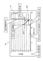
図5は、1つの端子収容室に1個のコネクタ端子が収容される様子を、収容の各段階に分けて示す模式図である。また、図6は、図5に示されているコネクタ端子の収容が行われるときに表示される、保持部の移動距離に対する圧力の変化の一例を表したグラフである。尚、図5では、コネクタハウジング6及びコネクタ端子52が、図1や図4とは上下逆向きに示されている。図6に示されているグラフG1では、横軸に保持部11の移動距離(mm)がとられ、縦軸に保持部11に掛かる圧力(N)がとられている。このグラフG1において圧力の変化が実線L1で示されている。
FIG. 5 is a schematic diagram showing a state in which one connector terminal is housed in one terminal housing chamber in each stage of housing. FIG. 6 is a graph showing an example of a change in pressure with respect to the moving distance of the holding unit, which is displayed when the connector terminal shown in FIG. 5 is accommodated. In FIG. 5, the
まず、コネクタ端子52がコネクタハウジング6の端子収容室61に挿入される前(ステップS21)では、グラフG1に示されているように、保持部11に掛かる圧力は略ゼロである。この圧力状態は、コネクタ端子52の先端が、端子収容室61の内部におけるランス611に接触するまで続く(ステップS22)。
First, before the
ランス611は片持ち梁状の係止部であり、コネクタ端子52の挿入が進むと、このランス611がコネクタ端子52に押されて撓む(ステップS23)。コネクタ端子52には、ランス611の先端が進入することで、コネクタ端子52の戻りを抑える進入孔が設けられている。コネクタ端子52の挿入が進むにつれランス611の先端がこの進入孔の縁を乗り越えて復位して進入孔の内部に進入する(ステップS24)。
The
図6のグラフG1に示されているように、ステップS23からステップS24の段階では、コネクタ端子52の先端に押されてランス611が撓むと、このランス611からの反発力を受けて圧力が急上昇する。ランス611の先端が進入孔の内部に進入したタイミングが圧力変化のピークとなり(S24−1)、ここを過ぎると、ランス611が撓みからやや開放されるので圧力が低下する。ピークを過ぎてしばらくは、ランス611の上をコネクタ端子52の進入孔の縁が通過して徐々にランス611が進入しつつ復位する。この復位により徐々に圧力が低下する。やがて、ランス611の上をコネクタ端子52の進入孔の縁が通り過ぎることで、ランス611の復位が一気に進み進入孔への進入が完了する(S24−2)。
As shown in the graph G1 in FIG. 6, in the stage from step S23 to step S24, when the
ランス611の先端が進入孔に進入した後もコネクタ端子52は若干進み、その先端が、端子収容室61の奥側の壁612に当接すると止まる(ステップS25)。そして、コネクタ端子52の先端が奥側の壁612に当接したタイミングで、その当接による反発力で圧力が再び急上昇する。この急上昇は、制御部18が、移動部12に保持部11の移動を停止させるまで続く。
Even after the leading end of the
ここで、本実施形態では、このようにグラフ表示される圧力の変化に基づいて、作業者が、コネクタ端子52が端子収容室61に正常に収容されたか否かを判断する収容判断工程を行う。
Here, in the present embodiment, the worker performs a housing determination step of determining whether or not the
この収容判断工程は、圧力測定工程で測定される圧力の変化が、次のような正常変化となっているか否かを判断するものである。この正常変化とは、圧力が、第1閾値d11を超えた後、この第1閾値d11よりも低い第2閾値d12未満となってから再度第1閾値d11を超えてコネクタ端子52の収容が終わるという変化のことである。第1閾値d11は、ランス611がコネクタ端子52の進入孔に進入する際に生じる圧力上昇の閾値である。収容判断工程では、この第1閾値d11が、コネクタ端子52の先端が端子収容室61の奥側の壁612に当接したことの確認にも使われる。上述したように、ランス611がコネクタ端子52の進入孔に進入してしまうと圧力が低下するが、第2閾値d12は、ランス611が進入孔に十分に進入したことの目安となる、低下した圧力値である。
This accommodation determination step determines whether or not the change in the pressure measured in the pressure measurement step is a normal change as described below. This normal change means that after the pressure exceeds the first threshold value d11, the pressure becomes less than the second threshold value d12 lower than the first threshold value d11, then exceeds the first threshold value d11 again, and the housing of the
このように、上記の正常変化は、コネクタ端子52が、ランス611が進入孔に十分に進入して端子収容室61の奥に達したことを表す圧力変化となっている。
As described above, the normal change is a pressure change indicating that the
ここで、本実施形態では、2つの端子収容室61に2個のコネクタ端子52を挿入させることなる。基本的には、挿入させるコネクタ端子52の数が増えても、コネクタ端子52の先端相互間にズレがなく揃っていれば、挿入時の圧力変化は、図6に示されている1個のコネクタ端子52を挿入するときの圧力変化と同様の変化となる。
Here, in the present embodiment, two
図7は、2個のコネクタ端子の先端相互間にズレがなく揃っている場合の圧力変化の一例を表すグラフである。 FIG. 7 is a graph showing an example of a pressure change when the tip ends of the two connector terminals are aligned without deviation.
この図7に示されているグラフG2でも横軸に保持部11の移動距離がとられ、縦軸に保持部11に掛かる圧力がとられている。そして、圧力変化が実線L2で示されている。
In the graph G2 shown in FIG. 7, the horizontal axis indicates the moving distance of the holding
このグラフG2において実線L2で示されているように、2個のコネクタ端子52の先端相互間にズレがなく揃っている場合の圧力変化は、図6に示されている1個のコネクタ端子52の挿入時の圧力変化と略同形状の変化となる。即ち、2つの端子収容室61のランス611には、2個のコネクタ端子52の先端が略同時に接触して圧力が急上昇して第1閾値d21を超えてピークに至る。やがて、2つのランス611が、略同時に2個のコネクタ端子52の進入孔に進入して圧力が低下し、第2閾値d22未満となる。そして、2個のコネクタ端子52の先端が2つの端子収容室61の奥側の壁612に略同時に接触して圧力が急上昇して第1閾値d21を超えて挿入が終了する。
As shown by the solid line L2 in the graph G2, the pressure change when the tip ends of the two
従って、2つの端子収容室61に2個のコネクタ端子52を挿入させる本実施形態でも、コネクタ端子52が1個の場合と同様の収容判断工程によって、圧力の変化が正常変化となっているか否かを判断することができる。そして、その判断結果を以て、2個のコネクタ端子52が端子収容室61に正常に収容されたか否かを判断することができる。
Therefore, also in the present embodiment in which the two
このとき、2個のコネクタ端子52の先端相互間にズレが生じると、そのズレの程度に応じて、圧力の変化が図7に示されている正常変化から次のようにずれてくる。即ち、ズレが生じると、2個のコネクタ端子52の相互間で、ランス611が各コネクタ端子52の進入孔に進入するタイミングがずれてくる。ランス611がこの進入孔に進入するタイミングで圧力の変化にピークが現れることから、ズレが生じると、2個のコネクタ端子52の相互間でピークの出現位置にズレが生じることとなる。そして、ピークの位置ズレは、2個のコネクタ端子52の先端相互間のズレが大きくなるほど大きくなる。
At this time, if a gap occurs between the tips of the two
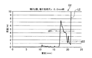
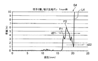
図8は、2個のコネクタ端子の先端相互間に0.5(mm)程度のズレが生じている場合の圧力変化の一例を表すグラフであり、図9は、2個のコネクタ端子の先端相互間に1.0(mm)程度のズレが生じている場合の圧力変化の一例を表すグラフである。 FIG. 8 is a graph showing an example of a pressure change when a deviation of about 0.5 (mm) occurs between the tips of two connector terminals, and FIG. It is a graph showing an example of a pressure change when a gap of about 1.0 (mm) occurs between each other.
この図8に示されているグラフG3でも横軸に保持部11の移動距離がとられ、縦軸に保持部11に掛かる圧力がとられ、圧力変化が実線L3で示されている。同様に、図9に示されているグラフG4でも横軸に保持部11の移動距離がとられ、縦軸に保持部11に掛かる圧力がとられ、圧力変化が実線L4で示されている。
In the graph G3 shown in FIG. 8, the horizontal axis indicates the moving distance of the holding
図8の例では、グラフG3において実線L3で示されているように、2個のコネクタ端子52の先端相互間のズレが0.5(mm)程度である場合には、ランス611が各コネクタ端子52の進入孔に進入するタイミングにそれほど大きなズレは生じない。このため、測定される圧力の変化も、図7に示されている正常変化に対して大差ない変化となる。つまり、この図8の例でも、圧力の変化は、正常変化であって、2個のコネクタ端子52が端子収容室61に正常に収容されたと判断されることとなる。また、先端相互間のズレが、この程度の微小なものである場合には、ランス611の進入孔への進入によって出現するピークにもほとんどズレが生じていないので、実質的に先端相互間のズレは生じていないと判断される。
In the example of FIG. 8, as shown by the solid line L3 in the graph G3, when the deviation between the tips of the two
これに対し、図9の例では、グラフG4において実線L4で示されているように、2個のコネクタ端子52の先端相互間のズレが1.0(mm)程度になると、ピークのズレが明確となる。即ち、先行するコネクタ端子52の進入孔にランス611が進入したタイミングで第1ピークP1が出現し、次のコネクタ端子52の進入孔にランス611が進入したタイミングで第2ピークP2が出現するようになる。
On the other hand, in the example of FIG. 9, as shown by the solid line L4 in the graph G4, when the deviation between the tips of the two
ただし、この図9の例では、2つのピークが現れる場合であっても、圧力の変化は、第1閾値d21を超えた後、第2閾値d22未満となってから再度第1閾値d21を超えるものとなっており、まだ正常変化の範囲内であるといえる。この変化は、タイミングにズレはあっても、2個のコネクタ端子52の何れについても、ランス611が十分に進入孔への進入を果たした後に、各コネクタ端子52の先端が、端子収容室61の奥側の壁612に達したことを意味している。一方で、ランス611の進入孔への進入によって出現するピークについては、明確に認識され得る第1ピークP1と第2ピークP2の2つが現れている。このため、図9の例では、2個のコネクタ端子52の先端相互間にズレが生じている旨が判断される。ただし、上述したように、図9の例では、2つのピークの出現から先端相互間のズレが判断されるものの、上記のように圧力の変化は正常変化であって、2個のコネクタ端子52が端子収容室61に正常に収容されたと判断されることとなる。
However, in the example of FIG. 9, even when two peaks appear, the change in the pressure exceeds the first threshold d21, becomes less than the second threshold d22, and then exceeds the first threshold d21 again. It can be said that it is still within the range of normal change. This change is caused by the fact that the tip of each
ところが、2個のコネクタ端子52の先端相互間のズレが更に大きくなると、次のような状況が生じることがある。即ち、先行してランス611が進入孔に進入したコネクタ端子52の先端が、後続のコネクタ端子52の進入孔にランス611が十分に進入しきる前に、端子収容室61の奥の壁612に当接してしまうという状況が生じることがある。この場合、後続のコネクタ端子52については、ランス611の係止が不十分な状態となり、端子収容室61への収容が正常ではないということとなる。本実施形態では、このように端子収容室61への収容が正常ではないことが、収容判断工程によって、以下に説明するように見いだされることとなる。
However, if the displacement between the tips of the two
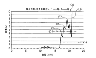
図10は、2個のコネクタ端子の先端相互間に2.0(mm)程度のズレが生じている場合の圧力変化の一例を表すグラフである。 FIG. 10 is a graph illustrating an example of a pressure change when a deviation of about 2.0 (mm) occurs between the tips of two connector terminals.
この図10に示されているグラフG5でも横軸に保持部11の移動距離がとられ、縦軸に保持部11に掛かる圧力がとられ、圧力変化が実線L5で示されている。
In the graph G5 shown in FIG. 10, the horizontal axis represents the movement distance of the holding
図10の例では、グラフG5において実線L5で示されているように、圧力の変化に、第1ピークP3と第2ピークP4が生じており、2個のコネクタ端子52の先端相互間にズレが生じていると判断される。更に、この圧力の変化は、第1閾値d21を超えた後、第2閾値d22未満となる前に再度第1閾値d21を超えるものとなっており、正常変化ではないと判断される。この変化は、上述したように、先行するコネクタ端子52の先端が、後続のコネクタ端子52の進入孔にランス611が十分に進入しきる前に、端子収容室61の奥の壁612に当接したことを表している。つまり、この図10の例については、2つのピークの出現から先端相互間のズレが判断され、かつ、2個のコネクタ端子52が端子収容室61に正常に収容されていないと判断されることとなる。
In the example of FIG. 10, as shown by the solid line L5 in the graph G5, a first peak P3 and a second peak P4 occur in the change in pressure, and the gap between the tips of the two
尚、本実施形態では、収容判断工程の一例として、2個のコネクタ端子52について収容を行い、正常に収容されたか否かを判断する形態が例示されている。しかしながら、この収容判断工程は、図6を参照して説明したように、コネクタ端子52が1個であっても、その収容が正常に行われたか否かを判断することができる。また、コネクタ端子52が3個以上であっても、それらの収容が正常に行われたか否かを判断することができる。
Note that, in the present embodiment, as an example of the accommodation determination process, an embodiment is described in which the accommodation is performed on the two
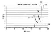
図11は、コネクタ端子の数が3個以上であることの一例として3個のコネクタ端子の収容を例に挙げ、そのときの収容判断工程について説明する図である。この図11には、3個のコネクタ端子52の先端相互間に、1.0(mm)程度と2.0(mm)程度との2種類のズレが生じている場合の圧力変化の一例を表すグラフG6が示されている。
FIG. 11 is a diagram illustrating an example of the case where the number of connector terminals is three or more, in which housing of three connector terminals is taken as an example, and a housing determination step at that time. FIG. 11 shows an example of a pressure change when two types of deviations of about 1.0 (mm) and about 2.0 (mm) are generated between the tips of the three
この図11に示されているグラフG6でも横軸に保持部11の移動距離がとられ、縦軸に保持部11に掛かる圧力がとられ、圧力変化が実線L6で示されている。
Also in the graph G6 shown in FIG. 11, the horizontal axis indicates the movement distance of the holding
図11の例では、グラフG6において実線L6で示されているように、3個のコネクタ端子52の先端相互間にズレが生じていることから、圧力の変化に、第1ピークP5と第2ピークP6と第3ピークP7との3つのピークが現れている。そして、ズレが大きいことから、この図11の例でも、後続のコネクタ端子52にランス611が十分に進入しきる前に、先行するコネクタ端子52の先端が端子収容室61の奥の壁612に当接してしまっている。これを受けて、実線L6が表わす圧力の変化は、第1閾値d31を超えた後、第2閾値d32未満となる前に再度第1閾値d31を超えるものとなっており、正常変化ではないと判断される。つまり、この図11の例については、3つのピークの出現から先端相互間のズレが判断され、かつ、3個のコネクタ端子52が端子収容室61に正常に収容されていないと判断されることとなる。
In the example of FIG. 11, as shown by the solid line L6 in the graph G6, there is a deviation between the tips of the three
以上に説明した本実施形態の端子挿入方法では、コネクタ端子52の挿入中に、そのコネクタ端子52を保持した保持部11に掛かる圧力の変化形状に基づいて、コネクタ端子52が端子収容室61に正常に収容されたか否かが判断される。このため、この判断において正常に収容されたと判断されたコネクタ端子52については、その後に各コネクタ端子52に対する引張り検査等を行わなくても十分な挿入が保障される。そして、上記の判断は、保持部11が保持したコネクタ端子52から最外被覆部分53までの間に露出した電線の長さ(首下長)とは無関係に行われる。首下長が短い場合には引張り検査を行うためのストロークを確保できず、引張り検査による挿入保障が困難となることがある。しかしながら、本実施形態の端子挿入方法によれば、コネクタ端子52が圧着接続された電線51の首下長に関わらず、コネクタ端子52の十分な挿入を保障することができる。
According to the terminal insertion method of the present embodiment described above, during the insertion of the
また、本実施形態の端子挿入方法では、2個のコネクタ端子52の同時挿入中に保持部11に掛かる圧力の変化形状に基づいて、2個のコネクタ端子52の先端相互間におけるズレの有無も判断される。このようなズレは、図10を参照して説明したように、あるいは図11を参照してコネクタ端子52の数が3個である別例について説明したように、複数のコネクタ端子52の挿入不良の発生原因となることがある。本実施形態の端子挿入方法によれば、このような発生原因の有無も含めて複数のコネクタ端子52の十分な挿入を保障することができる。
In the terminal insertion method according to the present embodiment, the presence or absence of displacement between the tips of the two
また、本実施形態の端子挿入方法では、収容工程における保持部11の移動中に、距離測定部13により保持部11の移動距離を測定する距離測定工程が行われる。収容判断工程は、図6〜図11を参照して説明したように、移動距離に対する圧力の変化に基づいて判断が行われる。保持部11の移動距離は、挿入中のコネクタ端子52が、端子収容室61に対して相対的にどのような位置にあるのかを示している。本実施形態の端子挿入方法によれば、仮に挿入不良が生じた場合に、端子収容室61におけるどの様な箇所で挿入不良が生じたのかを判断することもできる。
In the terminal insertion method of the present embodiment, a distance measuring step of measuring the moving distance of the holding
また、本実施形態の端子挿入方法では、保持部11の移動につれて、保持部11の一部である突起112によって押圧されることにより保持部11の移動距離を測定する接触方式の計測器としてマグネスケール(登録商標)が採用されている。このような接触方式の計測器では移動距離が直に測定されるので、計測結果としてのデータの取扱い等が容易であり、良好な作業性のもとで移動距離を測定することができる。
Further, in the terminal insertion method of the present embodiment, as the contact portion measuring device measures the moving distance of the holding
また、このような端子挿入方法に用いられる本実施形態の端子挿入装置1によれば、コネクタ端子52を保持した保持部11に掛かる圧力が、保持部11の移動に伴う変化が確認可能なグラフ形式で出力される。これにより、出力された圧力に基づいて、上述した2つの閾値を用いた判断により、コネクタ端子52が端子収容室61に正常に収容されたか否かを判断するという運用を行うことができる。このような運用は、上述したように保持部11が保持したコネクタ端子52が圧着接続された電線51の首下長とは無関係に行われる。従って、本実施形態の端子挿入装置1によれば、コネクタ端子52が圧着接続された電線51の首下長に関わらず、コネクタ端子52の十分な挿入を保障することができる。
Further, according to the
また、本実施形態の端子挿入装置1によれば、2個のコネクタ端子52を同時挿入できるとともに、それら2個のコネクタ端子52に対して、上述したようにコネクタ端子52の十分な挿入を保障することができる。
Further, according to the
また、本実施形態の端子挿入装置1では、出力部15が、保持部11の移動距離に対する圧力の変化が確認可能なグラフ形式で出力する。これにより、上述したように、挿入不良が生じた場合に、端子収容室61におけるどの様な箇所でコネクタ端子52の挿入不良が生じたのかを判断することもできる。
Further, in the
また、本実施形態の端子挿入装置1では、距離測定部13に、接触方式の計測器としてマグネスケール(登録商標)が採用されている。これにより、上述したように良好な作業性のもとで移動距離を測定することができる。
Further, in the
尚、以上に説明した実施形態は本発明の代表的な形態を示したに過ぎず、本発明は、これらの実施形態に限定されるものではない。即ち、本発明の骨子を逸脱しない範囲で種々変形して実施することができる。かかる変形によってもなお本発明の端子ズレ量検知方法、端子挿入方法、端子ズレ量検知装置、及び端子挿入装置の構成を具備する限り、勿論、本発明の範疇に含まれるものである。 The embodiments described above merely show typical embodiments of the present invention, and the present invention is not limited to these embodiments. That is, various modifications can be made without departing from the gist of the present invention. Such a modification is, of course, included in the scope of the present invention, as long as it has the configuration of the terminal displacement amount detection method, the terminal insertion method, the terminal displacement amount detection device, and the terminal insertion device of the present invention.
例えば、上述した実施形態では、ズレ量g11の取得や、ズレ量g11が閾値未満であるか否かの判断が制御部18によって自動的に行われる形態が例示されている。しかしながら、ズレ量g11の取得や上記の判断は、例えば出力部15に出力表示される移動距離に基づいて作業者が計算して行ってもよい。
For example, in the above-described embodiment, an example is described in which the
また、上述した実施形態や別例では、本発明にいう複数のコネクタ端子の一例として、2芯のツイストケーブル5における2本の電線51それぞれの端部に圧着接続された2個のコネクタ端子52が例示されている。しかしながら、本発明にいう複数のコネクタ端子は、これに限るものではなく、その具体的な個数を問うものではない。
In the above-described embodiment and other examples, as an example of the plurality of connector terminals according to the present invention, two
また、上述した実施形態や別例では、本発明にいう通過検知部の一例として、発光部141と受光部142とを備える光学的な通過検知部14が例示されている。しかしながら、本発明にいう通過検知部は、これらに限るものではなく、例えばコネクタ端子の先端の接触圧を検知する等といった光学以外の手法を用いたもの等であってもよい。
In the above-described embodiments and other examples, the optical
また、上述した実施形態や別例では、保持部11の移動を、制御部18の制御の下で、モータを有する移動部12で行う形態が例示されている。しかしながら、本発明はこれらに限るものではなく、手動の移動機構を有する移動部を設け、作業者が例えばハンドル操作等の手作業で移動部を操作して保持部を直進移動させるもの等であってもよい。
Further, in the above-described embodiment and other examples, the mode in which the movement of the holding
また、上述した実施形態では、本発明にいう距離測定部の一例として、ハウジング保持部16に取り付けられたマグネスケール(登録商標)を採用した距離測定部13が例示されている。しかしながら、本発明にいう距離測定部は、これに限るものではなく、コネクタ端子の保持部に、直進部の先端をハウジング保持部に向けて取り付けられたマグネスケール(登録商標)を採用したもの等であってもよい。この場合、ハウジング保持部が、保持部の進行方向の前方に配置されて、計測器としてのマグネスケール(登録商標)を押圧する物体の一例に相当する。
In the above-described embodiment, the
また、本発明にいう距離測定部は、マグネスケール(登録商標)に限るものではなく、例えばスピンドルの直進移動を歯車によって機械的に拡大して指針を旋回させてスピンドルの移動距離を指針で指し示すダイヤルゲージ等であってもよい。ダイヤルゲージを用いる場合でも、その設置場所は、コネクタ端子の保持部でもよく、あるいはハウジング保持部であってもよい。 Further, the distance measuring unit according to the present invention is not limited to Magnescale (registered trademark). For example, the linear movement of the spindle is mechanically enlarged by a gear and the pointer is turned to indicate the moving distance of the spindle with the pointer. It may be a dial gauge or the like. Even when a dial gauge is used, the installation location may be a connector terminal holding portion or a housing holding portion.
また、本発明にいう距離測定部は、マグネスケール(登録商標)やダイヤルゲージのような接触式の計測器に限るものでもない。本発明にいう距離測定部は、例えば超音波やレーザ光を対象物に当ててその反射を検知することで対象物までの距離を測定する非接触式の計測器であってもよい。この場合も、ハウジング保持部を対象物として計測器をコネクタ端子の保持部に設けてもよく、あるいは、コネクタ端子の保持部を対象物として計測器をハウジング保持部に設けてもよい。また、本発明にいう距離測定部は、コネクタ端子の保持部やハウジング保持部とは離れて配置された撮影装置で保持部の動きを撮影し、撮影された画像に対する画像解析により保持部の移動距離を求める撮影システム等であってもよい。 Further, the distance measuring unit according to the present invention is not limited to a contact type measuring instrument such as Magnescale (registered trademark) or a dial gauge. The distance measuring unit according to the present invention may be a non-contact type measuring device that measures a distance to an object by, for example, irradiating the object with ultrasonic waves or laser light and detecting its reflection. Also in this case, a measuring instrument may be provided on the holding section of the connector terminal with the housing holding section as the target, or a measuring instrument may be provided on the housing holding section with the holding section of the connector terminal as the target. In addition, the distance measuring unit according to the present invention captures the movement of the holding unit using an image capturing device that is disposed apart from the connector terminal holding unit and the housing holding unit, and moves the holding unit by performing image analysis on the captured image. An imaging system or the like for obtaining a distance may be used.
また、上述した実施形態では、コネクタ端子52の挿入に当たって、設計段階で予め求めておいた挿入完了距離をそのまま用い、保持部11の移動距離がその挿入完了距離に達するまで保持部11を直進移動させる形態が例示されている。しかしながら、保持部11に対する移動制御はこれに限るものではない。例えば、閾値未満となったズレ量g11に基づいて挿入完了距離を補正し、その補正済みの挿入完了距離を用いて保持部11に対する移動制御を行うこととしてもよい。具体的には、次のような補正に基づく移動制御が挙げられる。上述した実施形態では端子挿入に係る保持部11の移動が後続のコネクタ端子52が目標点522aに達した位置からスタートするので、挿入完了距離をそのまま用いると先行するコネクタ端子52が許容範囲内ではあるもののやや挿入過多となりがちである。そこで、例えば挿入完了距離からズレ量g11の半値を差し引く補正を行ない、補正済みの挿入完了距離を用いて保持部11に対する移動制御を行うこととしてもよい。これにより、後続のコネクタ端子52の挿入不足を抑えつつ先行するコネクタ端子52についての挿入過多も抑制することができる。この場合、補正済みの挿入完了距離が、本発明にいう「予め求めておいた」挿入完了距離の一例に相当する。ここにいう「予め求めておいた」とは、コネクタ端子52の挿入開始までであれば、設計段階であっても、開始直前の補正段階であっても何れのタイミングをも含んでいる。
In the above-described embodiment, when inserting the
1 端子挿入装置
5 ツイストケーブル
6 コネクタハウジング
11 保持部
12 移動部
13 距離測定部
14 通過検知部
14a センサ光
15 出力部
16 ハウジング保持部
16a 挿入口
17 電線色検知部
18 制御部
19 入力部
20 圧力測定部
51 電線
52 コネクタ端子
53 最外被覆部分
61 端子収容室
111 保持板
111a 保持溝
111b 挟持部
131 直進部
132 受け部
141 発光部
142 受光部
521 圧着部
522 進路
522a 目標点
611 ランス
612 壁
d11,d21,d31 第1閾値
d12,d22,d32 第2閾値
g11 ズレ量
D11 進行方向
D12 矢印
D13 配列方向
D14 方向
I11 情報
P1,P3,P5 第1ピーク
P2,P4,P6 第2ピーク
P7 第3ピーク
DESCRIPTION OF
Claims (17)
前記複数のコネクタ端子それぞれの進路を当該複数のコネクタ端子の配列方向に見た側面視で互いに一致する、当該進路における目標点の、前記複数のコネクタ端子それぞれの先端の通過を検知する通過検知工程と、
前記複数のコネクタ端子それぞれの先端について前記通過が検知されたときの前記移動距離に基づいて、前記複数のコネクタ端子それぞれの先端相互間のズレ量を求めるズレ量取得工程と、
を備えることを特徴とする端子ズレ量検知方法。 A plurality of connector terminals, each of which is crimped and connected to the end of the wire, are held in a row in parallel with each other. A moving process of moving straight while measuring the moving distance;
A passage detecting step of detecting a passage of a tip of each of the plurality of connector terminals at a target point on the course, wherein paths of the plurality of connector terminals coincide with each other in a side view as viewed in an arrangement direction of the plurality of connector terminals. When,
A shift amount obtaining step of calculating a shift amount between the respective tip ends of the plurality of connector terminals based on the movement distance when the passage is detected for the tips of the plurality of connector terminals,
A terminal displacement amount detection method, comprising:
前記複数のコネクタ端子それぞれの進路を当該複数のコネクタ端子の配列方向に見た側面視で互いに一致する、当該進路における目標点の、前記複数のコネクタ端子それぞれの先端の通過を検知する通過検知工程と、
前記複数のコネクタ端子それぞれの先端について前記通過が検知されたときの前記移動距離に基づいて、前記複数のコネクタ端子それぞれの先端相互間のズレ量を求めるズレ量取得工程と、
前記ズレ量が所定の閾値未満の場合に、前記保持部を更に直進移動させて、前記複数のコネクタ端子それぞれの前記進路に複数の端子収容室が一対一に位置するように配置されたコネクタハウジングの前記複数の端子収容室に前記複数のコネクタ端子を同時挿入する挿入工程と、
を備えることを特徴とする端子挿入方法。 A plurality of connector terminals, each of which is crimped and connected to the end of the wire, are held in a row in parallel with each other. A moving process of moving straight while measuring the moving distance;
A passage detecting step of detecting a passage of a tip of each of the plurality of connector terminals at a target point on the course, wherein paths of the plurality of connector terminals coincide with each other in a side view as viewed in an arrangement direction of the plurality of connector terminals. When,
A shift amount obtaining step of calculating a shift amount between the respective tip ends of the plurality of connector terminals based on the movement distance when the passage is detected for the tips of the plurality of connector terminals,
When the displacement amount is less than a predetermined threshold value, the holding portion is further moved in a straight line, and a connector housing is arranged such that a plurality of terminal accommodating chambers are located one-to-one on the respective paths of the plurality of connector terminals. An insertion step of simultaneously inserting the plurality of connector terminals into the plurality of terminal receiving chambers,
A terminal insertion method, comprising:
前記挿入工程が、前記閾値未満の前記ズレ量が求められた場合に前記複数のコネクタ端子それぞれの先端のうち何れか1つの前記通過が検知されたときの前記保持部の位置をゼロ位置とし、当該ゼロ位置からの前記移動距離が、前記挿入完了距離に達するまで直進移動させる工程であることを特徴とする請求項5に記載の端子挿入方法。 The insertion completion distance is a moving distance of the holding portion enough to insert all of the plurality of connector terminals, each of which is located at the target point, into the plurality of terminal accommodating chambers,
The insertion step, when the displacement amount less than the threshold is determined, the position of the holding unit when the passage of any one of the tips of the plurality of connector terminals is detected as the zero position, 6. The terminal insertion method according to claim 5, wherein the terminal is moved straight until the movement distance from the zero position reaches the insertion completion distance.
部によって保持されており、
前記移動距離の測定が、前記保持部の移動につれて、前記保持部又は前記ハウジング保持部によって押圧されることにより前記保持部の移動距離を測定する接触方式の計測器を用いて行われることを特徴とする請求項4〜6のうち何れか一項に記載の端子挿入方法。 The connector housing is held by a housing holding portion disposed in front of the holding portion in the traveling direction,
The measurement of the moving distance is performed using a contact-type measuring device that measures the moving distance of the holding unit by being pressed by the holding unit or the housing holding unit as the holding unit moves. The terminal insertion method according to any one of claims 4 to 6.
前記保持部を、前記複数のコネクタ端子それぞれの先端を進行方向に向けて直進移動させる移動部と、
前記保持部の前記進行方向への移動距離を測定する距離測定部と、
前記複数のコネクタ端子それぞれの進路を当該複数のコネクタ端子の配列方向に見た側面視で互いに一致する、当該進路における目標点の、前記複数のコネクタ端子それぞれの先端の通過を検知する通過検知部と、
前記複数のコネクタ端子それぞれの先端について前記通過が検知されたときの前記移動距離に基づいて、前記複数のコネクタ端子それぞれの先端相互間のズレ量を求めるズレ量取得部と、
を備えたことを特徴とする端子ズレ量検知装置。 A plurality of connector terminals, each of which is crimp-connected to the end of the electric wire, and a holding unit that holds the plurality of connector terminals arranged in a line in parallel with each other,
A moving unit that linearly moves the tip of each of the plurality of connector terminals in the traveling direction,
A distance measuring unit that measures a moving distance of the holding unit in the traveling direction,
A passage detecting unit that detects passage of a tip of each of the plurality of connector terminals at a target point on the course, wherein paths of the plurality of connector terminals coincide with each other in a side view when viewed in an arrangement direction of the plurality of connector terminals. When,
A shift amount obtaining unit that calculates a shift amount between the tips of the plurality of connector terminals based on the movement distance when the passage of the plurality of connector terminals is detected.
A terminal displacement amount detecting device comprising:
前記保持部を、前記複数のコネクタ端子それぞれの先端を進行方向に向けて直進移動させる移動部と、
前記保持部の前記進行方向への移動距離を測定する距離測定部と、
前記複数のコネクタ端子それぞれの進路を当該複数のコネクタ端子の配列方向に見た側面視で互いに一致する、当該進路における目標点の、前記複数のコネクタ端子それぞれの先端の通過を検知する通過検知部と、
コネクタハウジングを、前記複数のコネクタ端子それぞれの前記進路に複数の端子収容室が一対一に位置するように保持するハウジング保持部と、
前記複数のコネクタ端子それぞれの先端について前記通過が検知されたときの前記移動距離に基づいて、前記複数のコネクタ端子それぞれの先端相互間のズレ量を求めるズレ量取得部と、
前記ズレ量が所定の閾値未満であることを表す情報を取得する情報取得部と、
前記情報取得部における前記情報の取得を受けて、前記移動部に前記保持部を更に直進移動させて、前記複数の端子収容室に前記複数のコネクタ端子を同時挿入する挿入制御部と、を備えることを特徴とする端子挿入装置。 A plurality of connector terminals, each of which is crimp-connected to the end of the electric wire, and a holding unit that holds the plurality of connector terminals arranged in a line in parallel with each other,
A moving unit that linearly moves the tip of each of the plurality of connector terminals in the traveling direction,
A distance measuring unit that measures a moving distance of the holding unit in the traveling direction,
A passage detecting unit that detects passage of a tip of each of the plurality of connector terminals at a target point on the course, wherein paths of the plurality of connector terminals coincide with each other in a side view when viewed in an arrangement direction of the plurality of connector terminals. When,
A housing holding portion that holds the connector housing such that a plurality of terminal accommodating chambers are located one-to-one on the paths of the plurality of connector terminals,
A shift amount obtaining unit that calculates a shift amount between the tips of the plurality of connector terminals based on the movement distance when the passage of the plurality of connector terminals is detected.
An information acquisition unit that acquires information indicating that the deviation amount is less than a predetermined threshold,
Receiving an acquisition of the information by the information acquisition unit, further moving the holding unit straightly to the moving unit, and simultaneously inserting the plurality of connector terminals into the plurality of terminal receiving chambers. A terminal insertion device characterized by the above-mentioned.
前記挿入制御部が、前記閾値未満の前記ズレ量が求められた場合に前記複数のコネクタ端子それぞれの先端のうち何れか1つの前記通過が検知されたときの前記距離測定部の測定結果をゼロにセットし、そのセット以降の前記距離測定部の測定結果が、前記挿入完了距離に達するまで直進移動させる工程であることを特徴とする請求項14に記載の端子挿入装置。 The insertion completion distance is a moving distance of the holding portion enough to insert all of the plurality of connector terminals, each of which is located at the target point, into the plurality of terminal accommodating chambers,
The insertion control unit sets the measurement result of the distance measurement unit to zero when the passage of any one of the tips of the plurality of connector terminals is detected when the displacement amount less than the threshold is obtained. 15. The terminal insertion device according to claim 14, wherein the terminal insertion device is configured to set the insertion result in a straight line until the measurement result of the distance measurement unit after the setting reaches the insertion completion distance.
Priority Applications (7)
| Application Number | Priority Date | Filing Date | Title |
|---|---|---|---|
| JP2017111656A JP6629263B2 (en) | 2017-06-06 | 2017-06-06 | Terminal displacement detection method, terminal insertion method, terminal displacement detection device, and terminal insertion device |
| PT2018009882A PT2018225321B (en) | 2017-06-06 | 2018-03-14 | Terminal offset amount detection method, terminal insertion method, terminal offset amount detection device, and terminal insertion device |
| MX2019014588A MX2019014588A (en) | 2017-06-06 | 2018-03-14 | Terminal offset amount detection method, terminal insertion method, terminal offset amount detection device, and terminal insertion device. |
| PCT/JP2018/009882 WO2018225321A1 (en) | 2017-06-06 | 2018-03-14 | Terminal offset amount detection method, terminal insertion method, terminal offset amount detection device, and terminal insertion device |
| CN201880037740.9A CN110741515B (en) | 2017-06-06 | 2018-03-14 | Terminal displacement amount detection method, terminal insertion method, terminal displacement amount detection device, and terminal insertion device |
| PT115951A PT115951B (en) | 2017-06-06 | 2018-03-14 | TERMINAL INSERTION METHOD AND TERMINAL INSERTION DEVICE |
| US16/668,365 US11223178B2 (en) | 2017-06-06 | 2019-10-30 | Terminal displacement amount detection method, terminal insertion method, terminal displacement amount detection device, and terminal insertion device |
Applications Claiming Priority (1)
| Application Number | Priority Date | Filing Date | Title |
|---|---|---|---|
| JP2017111656A JP6629263B2 (en) | 2017-06-06 | 2017-06-06 | Terminal displacement detection method, terminal insertion method, terminal displacement detection device, and terminal insertion device |
Publications (2)
| Publication Number | Publication Date |
|---|---|
| JP2018206631A JP2018206631A (en) | 2018-12-27 |
| JP6629263B2 true JP6629263B2 (en) | 2020-01-15 |
Family
ID=64566694
Family Applications (1)
| Application Number | Title | Priority Date | Filing Date |
|---|---|---|---|
| JP2017111656A Active JP6629263B2 (en) | 2017-06-06 | 2017-06-06 | Terminal displacement detection method, terminal insertion method, terminal displacement detection device, and terminal insertion device |
Country Status (6)
| Country | Link |
|---|---|
| US (1) | US11223178B2 (en) |
| JP (1) | JP6629263B2 (en) |
| CN (1) | CN110741515B (en) |
| MX (1) | MX2019014588A (en) |
| PT (2) | PT2018225321B (en) |
| WO (1) | WO2018225321A1 (en) |
Families Citing this family (1)
| Publication number | Priority date | Publication date | Assignee | Title |
|---|---|---|---|---|
| DE102019130288A1 (en) * | 2019-11-11 | 2021-05-12 | Metzner Holding GmbH | Device, method and system for assembling an electrical connector |
Family Cites Families (12)
| Publication number | Priority date | Publication date | Assignee | Title |
|---|---|---|---|---|
| JPH04132180A (en) * | 1990-09-21 | 1992-05-06 | Fujikura Ltd | Connector |
| JPH11260526A (en) * | 1998-03-06 | 1999-09-24 | Yazaki Corp | Device for inserting terminal provided with wire |
| AU2003277542A1 (en) * | 2002-11-05 | 2004-06-07 | Yazaki Corporation | Connector housing, connector housing marking method, and method of inserting terminal metal fitting into connector housing |
| JP4917418B2 (en) * | 2006-12-14 | 2012-04-18 | タイコエレクトロニクスジャパン合同会社 | Terminal insertion device |
| JP2010003432A (en) * | 2008-06-18 | 2010-01-07 | Yazaki Corp | Terminal treating method for multi-core electric cable |
| JP5051094B2 (en) * | 2008-10-15 | 2012-10-17 | 住友電装株式会社 | Terminal insertion failure judgment method |
| JP2010165516A (en) * | 2009-01-14 | 2010-07-29 | Sumitomo Wiring Syst Ltd | Connector assembling device with function of detecting incomplete terminal insertion |
| JP5670667B2 (en) * | 2010-07-22 | 2015-02-18 | 矢崎総業株式会社 | Terminal and terminal connector mounting method |
| JP5619587B2 (en) * | 2010-12-10 | 2014-11-05 | 矢崎総業株式会社 | Terminal insertion device and terminal insertion method |
| JP5595572B2 (en) * | 2013-09-27 | 2014-09-24 | 日本航空電子工業株式会社 | Electric wire holder and harness manufacturing apparatus and method using the same |
| JP2015130304A (en) * | 2014-01-09 | 2015-07-16 | 住友電装株式会社 | Electric wire processing device and manufacturing method of wiring module |
| JP6078030B2 (en) * | 2014-08-27 | 2017-02-08 | 矢崎総業株式会社 | Connector housing position detecting device and position detecting method |
-
2017
- 2017-06-06 JP JP2017111656A patent/JP6629263B2/en active Active
-
2018
- 2018-03-14 PT PT2018009882A patent/PT2018225321B/en active IP Right Grant
- 2018-03-14 MX MX2019014588A patent/MX2019014588A/en unknown
- 2018-03-14 PT PT115951A patent/PT115951B/en active IP Right Grant
- 2018-03-14 CN CN201880037740.9A patent/CN110741515B/en active Active
- 2018-03-14 WO PCT/JP2018/009882 patent/WO2018225321A1/en active Application Filing
-
2019
- 2019-10-30 US US16/668,365 patent/US11223178B2/en active Active
Also Published As
| Publication number | Publication date |
|---|---|
| JP2018206631A (en) | 2018-12-27 |
| PT115951B (en) | 2022-01-25 |
| PT2018225321B (en) | 2022-05-31 |
| WO2018225321A1 (en) | 2018-12-13 |
| US20200067253A1 (en) | 2020-02-27 |
| CN110741515B (en) | 2021-04-06 |
| US11223178B2 (en) | 2022-01-11 |
| MX2019014588A (en) | 2020-02-07 |
| CN110741515A (en) | 2020-01-31 |
| PT115951A (en) | 2021-06-03 |
Similar Documents
| Publication | Publication Date | Title |
|---|---|---|
| EP2689708B1 (en) | Endoscopic apparatus and measurement method | |
| EP3031385A1 (en) | Insertion system and method for adjusting shape detection characteristics of shape sensor | |
| US20120289778A1 (en) | Endoscope capable of displaying a scale for determination of the size of the target | |
| JP6590863B2 (en) | Terminal insertion method and terminal insertion device | |
| JP6629263B2 (en) | Terminal displacement detection method, terminal insertion method, terminal displacement detection device, and terminal insertion device | |
| US8764635B2 (en) | Endoscope apparatus | |
| CN115393331A (en) | Method and device for detecting substrate position abnormality | |
| JP5170622B2 (en) | Shape measuring method, program, and shape measuring apparatus | |
| US7362451B2 (en) | Sensor device | |
| US9240661B2 (en) | Apparatus for feeding crimp terminals on a carrier strip into a crimping press | |
| US10877106B2 (en) | Conduction inspection jig and inspection method of conduction pin | |
| JP5128992B2 (en) | Electric wire processing equipment | |
| JP6150579B2 (en) | Insertion device | |
| JP4337103B2 (en) | Wire mounting device and insertion structure | |
| US9027401B2 (en) | Method of evaluating a clamping portion of an electric wire and a terminal, and device for evaluating the clamping portion | |
| JP2017009469A (en) | Device for detection of terminal crimping failure | |
| JP4710647B2 (en) | Terminal measuring device | |
| JPH0765923A (en) | Connector and its inspection device | |
| TWI798100B (en) | Electronic device assembling device and electronic device assembling method | |
| JP2005166297A (en) | Inspection method of insulation displacement terminal and inspection device of the same | |
| JP2008020226A (en) | Otdr measuring device, terminator used for otdr measurement, and otdr measuring method | |
| JP6795784B2 (en) | In-hole inspection device | |
| JP2005079058A (en) | Connector inspection device and connector | |
| JP6401013B2 (en) | Endoscope system | |
| JP2020148773A (en) | Light beam triangulation apparatus |
Legal Events
| Date | Code | Title | Description |
|---|---|---|---|
| RD04 | Notification of resignation of power of attorney |
Free format text: JAPANESE INTERMEDIATE CODE: A7424 Effective date: 20180323 |
|
| A621 | Written request for application examination |
Free format text: JAPANESE INTERMEDIATE CODE: A621 Effective date: 20180810 |
|
| RD04 | Notification of resignation of power of attorney |
Free format text: JAPANESE INTERMEDIATE CODE: A7424 Effective date: 20180815 |
|
| A131 | Notification of reasons for refusal |
Free format text: JAPANESE INTERMEDIATE CODE: A131 Effective date: 20190903 |
|
| A521 | Request for written amendment filed |
Free format text: JAPANESE INTERMEDIATE CODE: A523 Effective date: 20191004 |
|
| TRDD | Decision of grant or rejection written | ||
| A01 | Written decision to grant a patent or to grant a registration (utility model) |
Free format text: JAPANESE INTERMEDIATE CODE: A01 Effective date: 20191126 |
|
| A61 | First payment of annual fees (during grant procedure) |
Free format text: JAPANESE INTERMEDIATE CODE: A61 Effective date: 20191204 |
|
| R150 | Certificate of patent or registration of utility model |
Ref document number: 6629263 Country of ref document: JP Free format text: JAPANESE INTERMEDIATE CODE: R150 |
|
| R250 | Receipt of annual fees |
Free format text: JAPANESE INTERMEDIATE CODE: R250 |
|
| S531 | Written request for registration of change of domicile |
Free format text: JAPANESE INTERMEDIATE CODE: R313531 |
|
| R350 | Written notification of registration of transfer |
Free format text: JAPANESE INTERMEDIATE CODE: R350 |
|
| R250 | Receipt of annual fees |
Free format text: JAPANESE INTERMEDIATE CODE: R250 |