JP6628731B2 - Patient interface with automatic positioning - Google Patents
Patient interface with automatic positioning Download PDFInfo
- Publication number
- JP6628731B2 JP6628731B2 JP2016553666A JP2016553666A JP6628731B2 JP 6628731 B2 JP6628731 B2 JP 6628731B2 JP 2016553666 A JP2016553666 A JP 2016553666A JP 2016553666 A JP2016553666 A JP 2016553666A JP 6628731 B2 JP6628731 B2 JP 6628731B2
- Authority
- JP
- Japan
- Prior art keywords
- patient
- patient interface
- face
- seal
- interface
- Prior art date
- Legal status (The legal status is an assumption and is not a legal conclusion. Google has not performed a legal analysis and makes no representation as to the accuracy of the status listed.)
- Expired - Fee Related
Links
Images


Classifications
-
- A—HUMAN NECESSITIES
- A61—MEDICAL OR VETERINARY SCIENCE; HYGIENE
- A61M—DEVICES FOR INTRODUCING MEDIA INTO, OR ONTO, THE BODY; DEVICES FOR TRANSDUCING BODY MEDIA OR FOR TAKING MEDIA FROM THE BODY; DEVICES FOR PRODUCING OR ENDING SLEEP OR STUPOR
- A61M16/00—Devices for influencing the respiratory system of patients by gas treatment, e.g. mouth-to-mouth respiration; Tracheal tubes
- A61M16/06—Respiratory or anaesthetic masks
- A61M16/0605—Means for improving the adaptation of the mask to the patient
-
- A—HUMAN NECESSITIES
- A61—MEDICAL OR VETERINARY SCIENCE; HYGIENE
- A61M—DEVICES FOR INTRODUCING MEDIA INTO, OR ONTO, THE BODY; DEVICES FOR TRANSDUCING BODY MEDIA OR FOR TAKING MEDIA FROM THE BODY; DEVICES FOR PRODUCING OR ENDING SLEEP OR STUPOR
- A61M16/00—Devices for influencing the respiratory system of patients by gas treatment, e.g. mouth-to-mouth respiration; Tracheal tubes
- A61M16/06—Respiratory or anaesthetic masks
- A61M16/0683—Holding devices therefor
-
- A—HUMAN NECESSITIES
- A61—MEDICAL OR VETERINARY SCIENCE; HYGIENE
- A61M—DEVICES FOR INTRODUCING MEDIA INTO, OR ONTO, THE BODY; DEVICES FOR TRANSDUCING BODY MEDIA OR FOR TAKING MEDIA FROM THE BODY; DEVICES FOR PRODUCING OR ENDING SLEEP OR STUPOR
- A61M16/00—Devices for influencing the respiratory system of patients by gas treatment, e.g. mouth-to-mouth respiration; Tracheal tubes
- A61M16/06—Respiratory or anaesthetic masks
- A61M16/0605—Means for improving the adaptation of the mask to the patient
- A61M16/0633—Means for improving the adaptation of the mask to the patient with forehead support
-
- A—HUMAN NECESSITIES
- A61—MEDICAL OR VETERINARY SCIENCE; HYGIENE
- A61M—DEVICES FOR INTRODUCING MEDIA INTO, OR ONTO, THE BODY; DEVICES FOR TRANSDUCING BODY MEDIA OR FOR TAKING MEDIA FROM THE BODY; DEVICES FOR PRODUCING OR ENDING SLEEP OR STUPOR
- A61M2205/00—General characteristics of the apparatus
- A61M2205/02—General characteristics of the apparatus characterised by a particular materials
- A61M2205/0272—Electro-active or magneto-active materials
- A61M2205/0283—Electro-active polymers [EAP]
-
- A—HUMAN NECESSITIES
- A61—MEDICAL OR VETERINARY SCIENCE; HYGIENE
- A61M—DEVICES FOR INTRODUCING MEDIA INTO, OR ONTO, THE BODY; DEVICES FOR TRANSDUCING BODY MEDIA OR FOR TAKING MEDIA FROM THE BODY; DEVICES FOR PRODUCING OR ENDING SLEEP OR STUPOR
- A61M2205/00—General characteristics of the apparatus
- A61M2205/02—General characteristics of the apparatus characterised by a particular materials
- A61M2205/0272—Electro-active or magneto-active materials
- A61M2205/0288—Electro-rheological or magneto-rheological materials
-
- A—HUMAN NECESSITIES
- A61—MEDICAL OR VETERINARY SCIENCE; HYGIENE
- A61M—DEVICES FOR INTRODUCING MEDIA INTO, OR ONTO, THE BODY; DEVICES FOR TRANSDUCING BODY MEDIA OR FOR TAKING MEDIA FROM THE BODY; DEVICES FOR PRODUCING OR ENDING SLEEP OR STUPOR
- A61M2205/00—General characteristics of the apparatus
- A61M2205/10—General characteristics of the apparatus with powered movement mechanisms
-
- A—HUMAN NECESSITIES
- A61—MEDICAL OR VETERINARY SCIENCE; HYGIENE
- A61M—DEVICES FOR INTRODUCING MEDIA INTO, OR ONTO, THE BODY; DEVICES FOR TRANSDUCING BODY MEDIA OR FOR TAKING MEDIA FROM THE BODY; DEVICES FOR PRODUCING OR ENDING SLEEP OR STUPOR
- A61M2205/00—General characteristics of the apparatus
- A61M2205/13—General characteristics of the apparatus with means for the detection of operative contact with patient, e.g. lip sensor
-
- A—HUMAN NECESSITIES
- A61—MEDICAL OR VETERINARY SCIENCE; HYGIENE
- A61M—DEVICES FOR INTRODUCING MEDIA INTO, OR ONTO, THE BODY; DEVICES FOR TRANSDUCING BODY MEDIA OR FOR TAKING MEDIA FROM THE BODY; DEVICES FOR PRODUCING OR ENDING SLEEP OR STUPOR
- A61M2205/00—General characteristics of the apparatus
- A61M2205/15—Detection of leaks
-
- A—HUMAN NECESSITIES
- A61—MEDICAL OR VETERINARY SCIENCE; HYGIENE
- A61M—DEVICES FOR INTRODUCING MEDIA INTO, OR ONTO, THE BODY; DEVICES FOR TRANSDUCING BODY MEDIA OR FOR TAKING MEDIA FROM THE BODY; DEVICES FOR PRODUCING OR ENDING SLEEP OR STUPOR
- A61M2205/00—General characteristics of the apparatus
- A61M2205/33—Controlling, regulating or measuring
- A61M2205/3306—Optical measuring means
- A61M2205/3313—Optical measuring means used specific wavelengths
-
- A—HUMAN NECESSITIES
- A61—MEDICAL OR VETERINARY SCIENCE; HYGIENE
- A61M—DEVICES FOR INTRODUCING MEDIA INTO, OR ONTO, THE BODY; DEVICES FOR TRANSDUCING BODY MEDIA OR FOR TAKING MEDIA FROM THE BODY; DEVICES FOR PRODUCING OR ENDING SLEEP OR STUPOR
- A61M2205/00—General characteristics of the apparatus
- A61M2205/33—Controlling, regulating or measuring
- A61M2205/3317—Electromagnetic, inductive or dielectric measuring means
-
- A—HUMAN NECESSITIES
- A61—MEDICAL OR VETERINARY SCIENCE; HYGIENE
- A61M—DEVICES FOR INTRODUCING MEDIA INTO, OR ONTO, THE BODY; DEVICES FOR TRANSDUCING BODY MEDIA OR FOR TAKING MEDIA FROM THE BODY; DEVICES FOR PRODUCING OR ENDING SLEEP OR STUPOR
- A61M2205/00—General characteristics of the apparatus
- A61M2205/33—Controlling, regulating or measuring
- A61M2205/332—Force measuring means
-
- A—HUMAN NECESSITIES
- A61—MEDICAL OR VETERINARY SCIENCE; HYGIENE
- A61M—DEVICES FOR INTRODUCING MEDIA INTO, OR ONTO, THE BODY; DEVICES FOR TRANSDUCING BODY MEDIA OR FOR TAKING MEDIA FROM THE BODY; DEVICES FOR PRODUCING OR ENDING SLEEP OR STUPOR
- A61M2205/00—General characteristics of the apparatus
- A61M2205/33—Controlling, regulating or measuring
- A61M2205/3331—Pressure; Flow
-
- A—HUMAN NECESSITIES
- A61—MEDICAL OR VETERINARY SCIENCE; HYGIENE
- A61M—DEVICES FOR INTRODUCING MEDIA INTO, OR ONTO, THE BODY; DEVICES FOR TRANSDUCING BODY MEDIA OR FOR TAKING MEDIA FROM THE BODY; DEVICES FOR PRODUCING OR ENDING SLEEP OR STUPOR
- A61M2205/00—General characteristics of the apparatus
- A61M2205/50—General characteristics of the apparatus with microprocessors or computers
- A61M2205/502—User interfaces, e.g. screens or keyboards
-
- A—HUMAN NECESSITIES
- A61—MEDICAL OR VETERINARY SCIENCE; HYGIENE
- A61M—DEVICES FOR INTRODUCING MEDIA INTO, OR ONTO, THE BODY; DEVICES FOR TRANSDUCING BODY MEDIA OR FOR TAKING MEDIA FROM THE BODY; DEVICES FOR PRODUCING OR ENDING SLEEP OR STUPOR
- A61M2205/00—General characteristics of the apparatus
- A61M2205/50—General characteristics of the apparatus with microprocessors or computers
- A61M2205/52—General characteristics of the apparatus with microprocessors or computers with memories providing a history of measured variating parameters of apparatus or patient
-
- A—HUMAN NECESSITIES
- A61—MEDICAL OR VETERINARY SCIENCE; HYGIENE
- A61M—DEVICES FOR INTRODUCING MEDIA INTO, OR ONTO, THE BODY; DEVICES FOR TRANSDUCING BODY MEDIA OR FOR TAKING MEDIA FROM THE BODY; DEVICES FOR PRODUCING OR ENDING SLEEP OR STUPOR
- A61M2205/00—General characteristics of the apparatus
- A61M2205/70—General characteristics of the apparatus with testing or calibration facilities
- A61M2205/702—General characteristics of the apparatus with testing or calibration facilities automatically during use
-
- A—HUMAN NECESSITIES
- A61—MEDICAL OR VETERINARY SCIENCE; HYGIENE
- A61M—DEVICES FOR INTRODUCING MEDIA INTO, OR ONTO, THE BODY; DEVICES FOR TRANSDUCING BODY MEDIA OR FOR TAKING MEDIA FROM THE BODY; DEVICES FOR PRODUCING OR ENDING SLEEP OR STUPOR
- A61M2230/00—Measuring parameters of the user
-
- A—HUMAN NECESSITIES
- A61—MEDICAL OR VETERINARY SCIENCE; HYGIENE
- A61M—DEVICES FOR INTRODUCING MEDIA INTO, OR ONTO, THE BODY; DEVICES FOR TRANSDUCING BODY MEDIA OR FOR TAKING MEDIA FROM THE BODY; DEVICES FOR PRODUCING OR ENDING SLEEP OR STUPOR
- A61M2230/00—Measuring parameters of the user
- A61M2230/63—Motion, e.g. physical activity
Description
本発明は、患者への呼吸可能なガスの流れを供給するための患者インタフェースに関する。本発明は特に、自動位置調節を備えた患者インタフェースに関する。更に、本発明は、斯かる患者インタフェースを含む圧補助システムに関する。 The present invention relates to a patient interface for supplying a flow of breathable gas to a patient. The invention particularly relates to a patient interface with automatic positioning. Further, the present invention relates to a pressure assist system including such a patient interface.
口及び/又は鼻をカバーするためのマスクといった患者インタフェースは、ガスを患者に供給するために用いられる。空気、清浄空気、酸素又は修飾された酸素といった斯かるガスは、加圧された態様又は加圧されていない態様で、患者インタフェースを介して患者へと提供される。 A patient interface, such as a mask to cover the mouth and / or nose, is used to supply gas to the patient. Such a gas, such as air, clean air, oxygen or modified oxygen, is provided to the patient via the patient interface in a pressurized or unpressurized manner.
幾つかの慢性疾患及び疾病については、斯かる患者インタフェースの患者への長期間の装着が必須となるか、又は少なくとも妥当なものとなる。 For some chronic illnesses and diseases, prolonged application of such patient interfaces to patients may be necessary or at least justified.
斯かる疾病の限定するものではない一例は、閉塞性睡眠時無呼吸又は閉塞性睡眠時無呼吸症候群(OSA)である。OSAは通常、上気道の閉塞により引き起こされる。OSAは、睡眠の間の呼吸における反復的な中断により特徴付けられ、通常は血液酸素飽和度の低下を伴う。これらの呼吸の中断は、無呼吸と呼ばれ、典型的には20乃至40秒継続する。上気道の閉塞は通常、睡眠の間に起こる身体の低減した筋緊張により引き起こされる。人間の気道は、つぶれ得るものであってそれにより睡眠の間に呼吸を妨害し得る、柔らかい組織の壁から成る。睡眠の間に舌の組織が喉の後方に動き、それにより空気の通路を遮断する。それ故、OSAは一般にいびきを伴う。 One non-limiting example of such a disease is obstructive sleep apnea or obstructive sleep apnea (OSA). OSA is usually caused by obstruction of the upper airway. OSA is characterized by repetitive interruptions in breathing during sleep, usually with decreased blood oxygen saturation. These interruptions in breathing are called apnea and typically last 20 to 40 seconds. Upper airway obstruction is usually caused by reduced muscle tone of the body that occurs during sleep. The human airway consists of soft tissue walls that can be crushed and thereby disturb breathing during sleep. During sleep, the tissue of the tongue moves behind the throat, thereby blocking the air passage. Therefore, OSA is generally accompanied by snoring.
OSAに対する、種々の侵襲的及び非侵襲的処置が知られている。最も強力な非侵襲的処置のひとつは、持続気道陽圧(CPAP)又は二相気道陽圧(BiPAP)の使用であり、ここでは、1本以上の管を含む患者回路を介して、患者インタフェースが圧力発生器に接続され、該圧力発生器が、加圧ガスを患者インタフェースに送り、患者の気道を開いたまま保つために患者の気道に送る。斯くして、典型的には睡眠の間に患者により装着された患者インタフェースによって、空気の陽圧が患者にもたらされる。 Various invasive and non-invasive treatments for OSA are known. One of the most powerful non-invasive procedures is the use of continuous positive airway pressure (CPAP) or biphasic positive airway pressure (BiPAP), where a patient interface is provided via a patient circuit that includes one or more tubes. Is connected to a pressure generator that delivers pressurized gas to the patient interface and to the patient's airway to keep the patient's airway open. Thus, a positive air pressure is provided to the patient by the patient interface typically worn by the patient during sleep.
斯かる患者インタフェースの例は、
−鼻の上にフィットし、鼻腔を通してガスを供給する、鼻マスク、
−口の上にフィットし、口を通して ガスを供給する、口マスク、
−鼻と口の両方の上にフィットし、両方にガスを供給する、フルフェイス型マスク、及び
−本発明内では患者インタフェースとみなされるものであり、鼻腔に直接にガスを供給する小型の鼻挿入具から成る、鼻枕(nasal pillow)
である。
An example of such a patient interface is
A nasal mask, which fits over the nose and delivers gas through the nasal cavity;
A mouth mask, which fits over the mouth and delivers gas through the mouth,
-A full-face mask that fits over both the nose and mouth and supplies gas to both; and-a small nose that is considered a patient interface within the present invention and supplies gas directly to the nasal cavity. Nasal pillow consisting of inserts
It is.
患者インタフェースは通常、或る種のヘッドギアを用いて、患者の頭部に位置決めされ着用される。患者インタフェースと患者の顔との間の気密な封止を提供するために、患者インタフェースは顔に対して十分なレベルの圧力で装着される必要があるため、患者インタフェースを着用することは不快なものとなり得る。患者インタフェースが適切にフィットしていないことは、圧力の損失に導き、治療処置に悪影響を与え得るため、患者インタフェースは適切にフィットさせられる必要もある。 The patient interface is typically positioned and worn on the patient's head using some form of headgear. Wearing a patient interface is uncomfortable because the patient interface must be fitted with a sufficient level of pressure on the face to provide a tight seal between the patient interface and the patient's face Can be something. The patient interface also needs to be properly fitted, as a poor fit of the patient interface can lead to pressure loss and adversely affect the therapeutic procedure.
患者インタフェースが睡眠の前に適切にフィットさせられ得るとしても、睡眠の間に、患者インタフェースに、特に患者インタフェースの前方の突出部に、力学的な圧力がかけられてしまうような位置に、ユーザが動いてしまい得る。睡眠の間に、患者インタフェースの位置は、例えば枕又はその他の外部的な障害物によって乱され得る。ユーザが寝返りを打ち、枕又はその他の外部的な障害物が患者インタフェースを動かし、それによって、患者インタフェースと患者の顔との間に界面において漏れが生じ、フィットが適切でない部分を介した圧力損失に帰着し得る。しかしながら、患者の気道における圧力の提供は、斯かる患者インタフェースの主たる目的のひとつである。それ故、斯かる圧力損失は、治療処置の効果を減少させてしまう。漏れのその他の原因は、患者が睡眠に入った直後の、顔の筋肉の弛緩であり得る。その結果として、顔面の硬さが変化し、患者インタフェースの漏れを引き起こす。 Even if the patient interface can be properly fitted prior to sleep, the user may be placed in a position where mechanical pressure is applied to the patient interface during sleep, especially on the protrusions in front of the patient interface. Can move. During sleep, the position of the patient interface may be disturbed, for example, by a pillow or other external obstacle. When the user rolls over, a pillow or other external obstruction moves the patient interface, causing a leak at the interface between the patient interface and the patient's face, and pressure loss through the poorly fit area Can result in However, providing pressure in the patient's airway is one of the primary goals of such a patient interface. Therefore, such pressure loss reduces the effectiveness of the therapeutic procedure. Another cause of leakage may be relaxation of facial muscles immediately after the patient has gone to sleep. As a result, the stiffness of the face changes, causing leakage of the patient interface.
患者インタフェースの位置が元の適切にフィットされた位置から移動させられたときに生じ得る更なる問題は、患者の顔において起こり得る赤い跡の形成である。 A further problem that can occur when the position of the patient interface is moved from its original properly fitted position is the possible formation of red marks on the patient's face.
上述した問題を解決しようとする、幾つかの試みが知られている。米国特許出願公開US2013/0118500A1は、気道陽圧(PAP)マスクのための能動的なヘッドギアストラップのセットを管理するための方法及びシステムであって、圧力センサにより該マスク内のガス圧力値を検出するステップと、該能動的なヘッドギアストラップのセットの調節を識別するためのプロセッサを用いて該マスク内に生じるガス圧力値を解析するステップと、該能動的なヘッドギアストラップのセットに該識別された調節を実行するステップと、を有する方法及びシステムを開示している。換言すれば、該ヘッドギアストラップは、該マスク内に生じるガス圧に依存して調節される。 Several attempts to solve the above-mentioned problems are known. US Patent Application Publication US2013 / 0118500A1 is a method and system for managing a set of active headgear straps for a positive airway pressure (PAP) mask, wherein a pressure sensor detects gas pressure values within the mask. Analyzing the gas pressure values generated in the mask using a processor to identify adjustments to the set of active headgear straps; and identifying the identified gas pressure values in the set of active headgear straps. Performing an adjustment. In other words, the headgear strap is adjusted depending on the gas pressure generated in the mask.
国際特許出願公開WO2013/183018A1は、クッション要素と電気活性高分子材料とを備えた患者インタフェースであって、該電気活性高分子材料は、該電気活性高分子材料の活性化の際に該クッション要素の位置を再調節することを可能とする、患者インタフェースを開示している。該電気活性高分子材料は、患者インタフェースと患者の顔との間の界面における温度を測定する温度センサによって制御されるか、又は、患者インタフェースと患者の顔との間の界面の種々の位置における圧力を測定する1つ以上の圧力センサにより制御される。該電気活性高分子材料は、該温度又は圧力が、特定の閾値を超えるか又は下回ると活性化される。 WO 2013/183018 A1 is a patient interface comprising a cushion element and an electroactive polymer material, the electroactive polymer material being activated upon activation of the electroactive polymer material. Discloses a patient interface that allows the position of the patient to be readjusted. The electroactive polymer material is controlled by a temperature sensor that measures the temperature at the interface between the patient interface and the patient's face, or at various locations at the interface between the patient interface and the patient's face. Controlled by one or more pressure sensors that measure pressure. The electroactive polymer material is activated when the temperature or pressure exceeds or falls below a certain threshold.
米国特許出願公開US2004/0163648A1は、関連する監視及び制御装置との使用のためのガスマスクを開示している。該マスク及びストラップ又はキャップ上の又はこれらの中の種々のタイプのセンサが、睡眠障害や呼吸障害を持つ患者の監視のため、又は麻酔のために用いられる。これらのセンサは、酸素濃度センサ、患者位置センサ、眼球運動センサ、漏れ検出センサ、EEG、EMG、EOG、ECG、PTT、マイクロフォン、心拍、血圧、酸素飽和度、温度、動きセンサ、位置センサ、光センサ、漏れ検出センサ及びガス供給センサを含む。 US Patent Application Publication US 2004/0163648 A1 discloses a gas mask for use with an associated monitoring and control device. Various types of sensors on or in the mask and strap or cap are used for monitoring patients with sleep or breathing disorders or for anesthesia. These sensors include oxygen concentration sensors, patient position sensors, eye movement sensors, leak detection sensors, EEG, EMG, EOG, ECG, PTT, microphone, heart rate, blood pressure, oxygen saturation, temperature, motion sensors, position sensors, light It includes a sensor, a leak detection sensor and a gas supply sensor.
しかしながら、上述した問題に関しては、依然として改善の余地がある。 However, there is still room for improvement regarding the above problems.
本発明の目的は、睡眠の間の患者インタフェースの意図しない位置の移動による、ガスの漏れ又は赤い跡の形成といった問題を、より効果的に克服する、代替の改善された患者インタフェースを提供することにある。 It is an object of the present invention to provide an alternative and improved patient interface that more effectively overcomes problems such as gas leaks or the formation of red marks due to unintended movement of the patient interface during sleep. It is in.
本発明の一態様によれば、呼吸可能なガスの流れを患者に供給するための患者インタフェースであって、
前記患者インタフェースが前記患者により装着されたときに、前記患者インタフェースと前記患者の顔との間の界面を封止するための封止部と、
前記患者の顔に対する前記封止部の識別された基準位置に対する、前記患者の顔に対する前記封止部の変位についての情報を含む、変位情報を生成するための変位センサを含む、検出ユニットと、
前記患者の顔に対して前記封止部の少なくとも一部を位置決めするための1つ以上のアクチュエータと、
前記変位信号に基づいて前記1つ以上のアクチュエータを作動させ、使用の間に前記患者の顔に対する前記封止部の少なくとも一部の位置を調節する、制御ユニットと、
を有する患者インタフェースが提示される。
According to one aspect of the invention, a patient interface for delivering a flow of breathable gas to a patient, the patient interface comprising:
A seal for sealing an interface between the patient interface and the patient's face when the patient interface is worn by the patient;
A detection unit, comprising: a displacement sensor for generating displacement information, including information about displacement of the seal relative to the patient's face, relative to an identified reference position of the seal relative to the patient's face;
One or more actuators for positioning at least a portion of the seal relative to the patient's face;
A control unit for actuating the one or more actuators based on the displacement signal to adjust a position of at least a portion of the seal relative to the patient's face during use;
Is presented.
本発明の好適な実施例は、従属請求項において定義される。請求の範囲の支持システムは、請求の範囲の患者インタフェースと及び従属請求項において定義されたものと同様の及び/又は同一の好適な実施例を持つことは、理解されるべきである。 Preferred embodiments of the invention are defined in the dependent claims. It should be understood that the claimed support system has a preferred and similar and / or identical preferred embodiment as defined in the claimed patient interface and in the dependent claims.
本発明は、患者の顔に対する患者インタフェースの最適な位置を再び得るため、患者インタフェースが自動的に位置を自己調節するための方法を提案する。斯くして患者は、睡眠の間に動く患者インタフェースによる乱れを、あまり被らなくなる。 The present invention proposes a method for the patient interface to self-adjust automatically in order to regain the optimal position of the patient interface with respect to the patient's face. Thus, the patient is less susceptible to disturbances due to the moving patient interface during sleep.
変位センサが、患者インタフェースの意図しない変位を感知し、制御ユニットが、感知された変位に応答して、患者の顔に対して患者インタフェースの封止部の少なくとも一部を再配置するよう、1つ以上のアクチュエータを作動させ得る。マスクのクッションがどれくらい柔らかいか/柔軟であるかに依存して、動いている顔に触れる領域なしで、顔に対してマスクの硬いプラスチック部(例えばマスク殻部)を枕が押すという問題が生じ得る。該調節は、このことを防止し得る。変位センサは特に、患者の顔に対する封止部の識別された基準位置に対する、患者インタフェースの封止部の変位を感知する。識別された基準位置は、患者インタフェースの封止部が患者の顔に適切にフィットされ、患者インタフェースと患者の顔との間の界面においてガスの漏れが生じない位置である。当該最適位置からの変位を感知し、最適位置を知ることにより、制御ユニットは、患者インタフェースの位置を調節し、患者インタフェースを再び最適位置に戻すことが可能であり、これにより生じ得るガスの漏れが、自動的に再び閉じられることとなる。 A displacement sensor senses an unintended displacement of the patient interface, and the control unit responds to the sensed displacement to reposition at least a portion of the patient interface seal relative to the patient's face. One or more actuators may be activated. Depending on how soft / soft the mask cushion is, the problem can arise where the pillow presses the hard plastic part of the mask (eg mask shell) against the face without any area of contact with the moving face obtain. The adjustment may prevent this. The displacement sensor particularly senses displacement of the seal of the patient interface relative to the identified reference position of the seal relative to the patient's face. The identified reference location is a location where the seal of the patient interface is properly fitted to the patient's face and there is no gas leakage at the interface between the patient interface and the patient's face. By sensing the displacement from the optimal position and knowing the optimal position, the control unit can adjust the position of the patient interface and return the patient interface to the optimal position again, which may result in gas leakage. Will be automatically closed again.
患者が睡眠の間に頭部を回転させ、例えば枕のようないずれかの外部の障害物が患者インタフェースを最適位置から離れるように動かした場合、このことは変位センサにより検出され、制御ユニットがこれに応じて1つ以上のアクチュエータを作動させて、患者インタフェースの封止部の少なくとも一部を、最適な位置に再び戻す。患者自身は、このことを認識しさえもしないこととなり得る。当該手法により空気の漏れは自動的に閉じられるため、全体的な治療処置が著しく改善される。 If the patient rotates his head during sleep and any external obstruction, such as a pillow, moves the patient interface away from the optimal position, this is detected by the displacement sensor and the control unit In response, one or more actuators are actuated to return at least a portion of the patient interface seal to the optimal position. The patient himself may not even realize this. The approach automatically closes the air leak, thus significantly improving the overall healing procedure.
国際特許出願公開WO2013/183018A1において提案された電気活性高分子材料が、センサとして利用されても良いことは、留意されるべきである。しかしながら、本発明により用いられる変位センサに比べて、国際特許出願公開WO2013/183018A1において記載された電気活性高分子材料は、該材料にかけられた絶対圧又は該材料の絶対変形を感知できるのみである。電気活性高分子材料は、患者の顔に対する封止部の変位即ちカバーされた距離を検出し得ないし、識別された基準位置に対する相対的な変位を感知することもできない。従って、国際特許出願公開WO2013/183018A1は、識別された基準位置に封止部を再配置する代わりに、電気活性高分子材料によって提供されるマッサージ効果の生成を示唆するものである。 It should be noted that the electroactive polymer material proposed in International Patent Application Publication WO2013 / 183018A1 may be used as a sensor. However, compared to the displacement sensor used according to the present invention, the electroactive polymer material described in WO 2013 / 183018A1 can only sense the absolute pressure applied to the material or the absolute deformation of the material . The electroactive polymer material cannot detect the displacement or covered distance of the seal relative to the patient's face, nor can it sense the relative displacement with respect to the identified reference position. Thus, International Patent Application Publication WO2013 / 183018A1 suggests the creation of a massage effect provided by an electroactive polymer material instead of relocating the seal at an identified reference location.
一実施例によれば、前記患者インタフェースは更に、前記患者の顔に対する前記封止部の前記識別された基準位置を保存するための記憶ユニットを有する。 According to one embodiment, the patient interface further comprises a storage unit for storing the identified reference position of the seal relative to the patient's face.
このことは例えば、患者の顔に対する封止部の基準位置の位置座標を保存することを可能とする。位置座標の代わりに、例えば最適基準位置において封止部によりカバーされる患者の顔における特徴のような、他の別個の基準特徴が、該記憶ユニットに保存されても良い。変位センサが、識別された基準位置の保存されたパラメータ又は特徴からの何らかの逸脱を検知するとすぐに、制御ユニットが1つ以上のアクチュエータを起動し、患者の顔に対して封止部の少なくとも一部を再調節して、封止部を最適な位置に戻す。 This makes it possible, for example, to store the position coordinates of the reference position of the seal relative to the patient's face. Instead of position coordinates, other separate reference features may be stored in the storage unit, for example features on the patient's face covered by the seal at the optimal reference position. As soon as the displacement sensor detects any deviation from the stored parameters or features of the identified reference position, the control unit activates one or more actuators and at least one of the seals against the patient's face. Readjust the part to return the seal to the optimal position.
更なる実施例によれば、前記患者インタフェースは更に入力インタフェースを有しても良く、前記入力インタフェースは、前記検出ユニットを起動し、前記患者による前記入力インタフェースの手動の作動に応じて、前記患者の顔に対する前記封止部の基準位置についての情報を前記記憶ユニットに保存するよう構成される。 According to a further embodiment, the patient interface may further comprise an input interface, which activates the detection unit and, in response to manual activation of the input interface by the patient, the patient interface And storing information about a reference position of the sealing portion with respect to the face of the user in the storage unit.
前記入力インタフェースは例えば、患者インタフェースが患者の顔に適切にフィットさせられるとすぐに該患者が触れる又は押下することができるボタンとして実現されても良い。ユーザが当該ボタンを触れる又は押下することに応答して、変位センサが基準位置を識別し、基準位置パラメータを記憶ユニットに保存する。患者の顔に対する封止部の意図しない動きによってこれらの位置パラメータが変化するとすぐに、制御ユニットが1つ以上のアクチュエータを起動して、以上に説明された態様で、患者の顔に対して封止部の少なくとも一部を再配置する。 The input interface may be implemented, for example, as a button that can be touched or pressed by the patient as soon as the patient interface is properly fitted to the patient's face. In response to the user touching or pressing the button, the displacement sensor identifies the reference position and stores the reference position parameters in the storage unit. As soon as these position parameters change due to unintended movement of the seal relative to the patient's face, the control unit activates one or more actuators and seals the patient's face in the manner described above. Reposition at least a portion of the stop.
代替の実施例においては、前記患者インタフェースは更に、前記患者インタフェースが前記患者に装着されたときに、前記患者の顔に対する前記封止部の前記基準位置を自動的に識別するための識別ユニットを有しても良い。 In an alternative embodiment, the patient interface further comprises an identification unit for automatically identifying the reference position of the seal relative to the patient's face when the patient interface is worn on the patient. You may have.
識別ユニットは例えば、患者の顔において目印検出を実行する光学センサにより、基準位置を自動的に識別しても良い。患者インタフェースの封止部の位置が患者の顔における特定の特徴的な目印に対応する場合、識別ユニットが検出ユニットを起動して、封止部の現在位置の位置パラメータを、基準位置の位置パラメータとして保存しても良い。 The identification unit may automatically identify the reference position by, for example, an optical sensor that performs landmark detection on the patient's face. If the position of the seal of the patient interface corresponds to a particular characteristic landmark on the patient's face, the identification unit activates the detection unit and changes the position parameter of the current position of the seal to the position parameter of the reference position. You may save as.
識別ユニットは代替として、患者インタフェースの内部におけるガス圧力を感知する圧力センサにより、封止部が最適位置(即ち基準位置)にあることを識別しても良い。該ガス圧力が特定の閾値を超える場合、このことは該患者インタフェースが適切にフィットさせられており、患者の顔に適切に配置されていることの示唆であり得るため、このとき該位置が基準位置として識別される。 The identification unit may alternatively identify that the seal is in the optimal position (ie, reference position) by a pressure sensor that senses gas pressure inside the patient interface. If the gas pressure exceeds a certain threshold, this may be an indication that the patient interface is properly fitted and properly positioned on the patient's face, so the position is then referenced. Identified as a location.
更なる代替例によれば、該基準位置は、該患者インタフェースが患者の顔に着用されたすぐ後に到達された位置として識別されても良く、これは患者が常に該患者の顔に対して患者インタフェースを適切に位置決めすることを仮定している。この場合、識別ユニットは例えば、患者インタフェースの動きを測定し、(患者インタフェースを患者の顔に着用する間に患者の手動の位置調節により引き起こされる)動きが終了するとすぐに、識別ユニットを起動して基準位置を識別する、加速度計を有しても良い。 According to a further alternative, the reference position may be identified as a position reached shortly after the patient interface is worn on the patient's face, which means that the patient always has the patient interface with the patient's face. It is assumed that the interface is properly positioned. In this case, the identification unit, for example, measures the movement of the patient interface and activates the identification unit as soon as the movement is completed (caused by manual positioning of the patient while putting the patient interface on the patient's face). May be provided with an accelerometer for identifying the reference position.
基準位置の自動的な識別の場合には、以上に説明されたような記憶ユニットは必ずしも必要とされないことは、留意されるべきである。基準位置の位置パラメータは、必ずしも保存される必要はない。その代わりに、識別ユニットが、単に信号を検出ユニットに送信して変位センサを作動させ、該変位センサが作動された後に変位が感知されるとすぐに、1つ以上のアクチュエータが作動させられるようにしても良い。 It should be noted that in the case of automatic identification of the reference position, a storage unit as described above is not necessarily required. The position parameters of the reference position need not always be stored. Instead, the identification unit simply activates the displacement sensor by sending a signal to the detection unit, so that one or more actuators are activated as soon as a displacement is sensed after the displacement sensor is activated. You may do it.
一実施例によれば、前記変位センサは、前記封止部内に又は前記封止部上に配置された、光学位置センサ、機械式センサ又は加速度センサを含む。 According to one embodiment, the displacement sensor comprises an optical position sensor, a mechanical sensor or an acceleration sensor located in or on the seal.
光学位置センサの一例は、CMOSセンサである。変位センサは封止部に必ずしも直接に配置される必要はなく、患者インタフェースにおいて又は患者インタフェースの他の部分において配置されても良いことは、留意されるべきである。機械式センサは例えば、一方の端においてマスクに装着され、他方の端においてユーザの顔に接触する、微細な「毛」状の構造として実現されても良い。マスクと顔との相対的な位置が動くと、このことが毛状センサを動かす。 One example of an optical position sensor is a CMOS sensor. It should be noted that the displacement sensor need not necessarily be located directly on the seal, but may be located at the patient interface or at other parts of the patient interface. The mechanical sensor may be implemented, for example, as a fine "hair" -like structure that is attached to the mask at one end and contacts the user's face at the other end. As the relative position of the mask and face moves, this moves the hair sensor.
更なる実施例によれば、前記検出ユニットは更に、前記患者インタフェースと前記患者の顔との間の界面における圧力についての情報を含む第1の圧力信号を生成するための第1のセンサを有し、前記制御ユニットは、前記変位信号及び前記第1の圧力信号に基づいて前記1つ以上のアクチュエータを作動させるよう構成される。 According to a further embodiment, the detection unit further comprises a first sensor for generating a first pressure signal comprising information about a pressure at an interface between the patient interface and the patient's face. The control unit is configured to activate the one or more actuators based on the displacement signal and the first pressure signal.
患者インタフェースと患者の顔との間の圧力を測定することにより、最適な性能のための正確な圧力が達成されることができ、睡眠の間に患者インタフェースの位置が意図せず移動してしまったときにもアクチュエータによって再調節されることができる。このことは特に、患者の顔における望ましくない赤い跡の形成を防止し得る。 By measuring the pressure between the patient interface and the patient's face, accurate pressure for optimal performance can be achieved and the position of the patient interface may unintentionally move during sleep. Can also be readjusted by the actuator. This may in particular prevent the formation of unwanted red marks on the patient's face.
更なる実施例によれば、前記検出ユニットは更に、外部の物体により外部から前記患者インタフェースにかけられた力についての情報を含む第2の圧力信号を生成するための第2の圧力センサを有し、前記制御ユニットは、前記変位信号及び前記第2の圧力信号に基づいて前記1つ以上のアクチュエータを作動させるよう構成される。 According to a further embodiment, the detection unit further comprises a second pressure sensor for generating a second pressure signal comprising information about a force externally applied to the patient interface by an external object. And the control unit is configured to activate the one or more actuators based on the displacement signal and the second pressure signal.
該第2の圧力センサは例えば、患者インタフェースの外側面に配置された圧力センサのアレイを含んでも良い。患者が睡眠の間に頭を回転させ、患者インタフェースを外部の障害物に押し付けた場合には、このことは第2の圧力センサにより感知され得る。次いでアクチュエータが、これらの感知された信号に応答して、患者インタフェースの封止部の位置を調節しても良い。このことは更に位置調節を改善させる。 The second pressure sensor may include, for example, an array of pressure sensors located on an outer surface of the patient interface. If the patient turns his head during sleep and presses the patient interface against an external obstacle, this may be sensed by the second pressure sensor. An actuator may then adjust the position of the patient interface seal in response to these sensed signals. This further improves the positioning.
更なる実施例においては、前記封止部は、クッション要素と、前記クッション要素を保持するためのマスク殻部と、を有し、前記1つ以上のアクチュエータは、使用の間の前記マスク殻部に対する及び前記患者の顔に対する前記クッション要素の位置を調節するため、前記クッション要素と前記マスク殻部との間に配置される。本実施例においては、変位が検出された場合に、クッション要素のみが再調節され、マスク殻部は変位させられた位置のままに留まり得る。 In a further embodiment, the seal comprises a cushion element and a mask shell for holding the cushion element, wherein the one or more actuators comprise the mask shell during use. The cushion element is positioned between the cushion element and the mask shell to adjust the position of the cushion element with respect to the patient's face. In this embodiment, if a displacement is detected, only the cushion element is readjusted and the mask shell may remain in the displaced position.
代替の実施例においては、前記封止部は、クッション要素と、前記クッション要素を保持するためのマスク殻部と、を有し、前記患者インタフェースは更に、中間構造を有し、前記中間構造は、ヘッドギアを前記中間構造に装着するための1つ以上の装着要素を有し、前記1つ以上のアクチュエータは、使用の間の前記中間構造に対する及び前記患者の顔に対する前記マスク殻部及び前記クッション要素の位置を調節するため、前記中間構造と前記マスク殻部との間に配置される。 In an alternative embodiment, the seal comprises a cushion element and a mask shell for holding the cushion element, wherein the patient interface further comprises an intermediate structure, wherein the intermediate structure is And one or more mounting elements for mounting headgear to the intermediate structure, wherein the one or more actuators include the mask shell and the cushion for the intermediate structure and for the patient's face during use. An element is arranged between the intermediate structure and the mask shell to adjust the position of the element.
上述した実施例とは異なり、クッション要素の位置のみならず、マスク全体(クッション要素及びマスク殻部を含むマスクの部分)の位置が再調節される。上述した中間構造は、マスク殻部をヘッドギアのストラップに結合するものであり、堅固なフレーム又は胴体部として実現されても良い。アクチュエータが当該堅固なフレーム/胴体部とマスクとの間に配置されるため、ヘッドギアのストラップは、該胴体部を適所に保持し、該ストラップの緊張は好適な封止の実現から切り離され、そのため快適さを容易に実現する。このことは特に、マスク殻部及びクッション要素の位置が容易な態様で調節されることができる一方、胴体部及びヘッドギアの位置が同じままでとどまり得るという利点をもたらす。 Unlike the embodiment described above, not only the position of the cushion element but also the position of the entire mask (the part of the mask including the cushion element and the mask shell) is readjusted. The intermediate structure described above couples the mask shell to the headgear strap and may be implemented as a rigid frame or body. Because the actuator is located between the rigid frame / body and the mask, the headgear strap holds the body in place and the tension on the strap is decoupled from providing a suitable seal, so Achieve comfort easily. This has in particular the advantage that the position of the mask shell and the cushion element can be adjusted in an easy manner, while the position of the body and the headgear can remain the same.
上述した2つの実施例(胴体部があるものとないもの)の両方において、前記1つ以上のアクチュエータは好適には、前記患者インタフェースと前記患者の顔との間の界面に垂直な方向を含む3つの空間的な方向に沿って、前記封止部の少なくとも一部を位置決めするよう構成される。それ故、前記封止部は、1つ以上のアクチュエータによって、全ての空間的な次元に沿って、即ち、患者インタフェースと患者の顔との間の界面に対して横方向(x及びy方向)にのみならず、該界面に垂直な方向(z方向)にも、動かされる/調節されることができる。このことは、位置を修正するときに、患者の顔から封止部を持ち上げることも可能とする。特に上述したように胴体部が備えられる場合には、患者インタフェース、特に封止部は、z方向に持ち上げられた後には、より容易にxy方向に再位置決めされ得る。他方で、マスク殻部及びクッション要素は、特定の量の治療継続時間の後、患者の顔から自動的に持ち上げられ/取り外されても良く、これにより、患者インタフェースの過度に長い装着による患者の顔における赤い跡の形成が防止されるようにしても良い。 In both of the two embodiments described above (with and without the torso), the one or more actuators preferably include a direction perpendicular to the interface between the patient interface and the patient's face. It is configured to position at least a portion of the seal along three spatial directions. Thus, the seal is moved by one or more actuators along all spatial dimensions, ie transversely to the interface between the patient interface and the patient's face (x and y directions). As well as in the direction perpendicular to the interface (z-direction). This also allows the seal to be lifted from the patient's face when correcting the position. The patient interface, especially the seal, can be more easily repositioned in the xy direction after being lifted in the z direction, especially if a body is provided as described above. On the other hand, the mask shell and cushioning element may be automatically lifted / removed from the patient's face after a certain amount of treatment duration, thereby allowing the patient interface to be worn too long by the patient interface. The formation of red marks on the face may be prevented.
更なる実施例においては、前記検出ユニットは更に、前記患者の睡眠状態についての情報を含む睡眠状態信号を感知するための睡眠センサを有し、前記制御ユニットは、前記変位信号及び前記睡眠状態信号に基づいて前記1つ以上のアクチュエータを作動させるよう構成される。 In a further embodiment, the detection unit further comprises a sleep sensor for sensing a sleep state signal including information about the sleep state of the patient, wherein the control unit includes the sleep signal and the sleep state signal. Is configured to actuate the one or more actuators based on
このことは例えば、OSA処置が必ずしも必要とされない覚醒状態又はREM睡眠の間に、患者の顔からクッション要素及びマスク殻部を持ち上げることを可能とする。しかしながら、クッション要素及びマスク殻部は、OSA処置が必要とされない別の睡眠相の間に患者の顔から持ち上げられても良いことは、留意されるべきである。睡眠状態は例えば、睡眠の間に患者の心拍数を感知する光電式容積脈波記録(photo-plethysmographic、PPG)センサによって感知されても良い。当該PPGセンサは、クッション要素に一体化されても良い。 This allows, for example, the lifting of the cushion element and mask shell from the patient's face during awake or REM sleep, where OSA treatment is not necessarily required. However, it should be noted that the cushion element and the mask shell may be lifted from the patient's face during another sleep phase where OSA treatment is not required. Sleep status may be sensed, for example, by a photo-plethysmographic (PPG) sensor that senses the patient's heart rate during sleep. The PPG sensor may be integrated with the cushion element.
一実施例においては、前記患者インタフェースは更に、前記封止部を前記患者の顔に着用させるための複数のヘッドギアストラップを含むヘッドギアを有し、前記1つ以上のアクチュエータは、前記複数のヘッドギアストラップの1つ以上を個々に調節することにより、前記患者の顔に対して前記封止部の少なくとも一部を位置決めするよう構成される。 In one embodiment, the patient interface further includes a headgear including a plurality of headgear straps for causing the seal to be worn on the patient's face, and wherein the one or more actuators include the plurality of headgear straps. Are configured to individually position at least a portion of the seal with respect to the patient's face.
前記1つ以上のアクチュエータは、例えば、1つ以上のヘッドギアストラップの緊張度又は位置を電気的に調節する電気モータとして実現されても良い。代替としては、該ヘッドギアストラップが、作動されるとヘッドギアの個々の部分の緊張度を変更する電気活性高分子を含んでも良い。 The one or more actuators may be implemented, for example, as an electric motor that electrically adjusts the tension or position of one or more headgear straps. Alternatively, the headgear strap may include an electroactive polymer that, when actuated, changes the tension of individual portions of the headgear.
一実施例においては、前記変位センサは、前記ヘッドギアのなか又は前記ヘッドギア上に配置されても良い。この場合、該変位センサは、該ヘッドギアの変位を感知することにより、患者インタフェースの封止部の変位を直接に感知する。 In one embodiment, the displacement sensor may be located in or on the headgear. In this case, the displacement sensor directly senses the displacement of the seal of the patient interface by sensing the displacement of the headgear.
上述した実施例の全てにおいて、前記制御ユニットが、前記識別された基準位置に前記封止部を戻すため、使用の間に、前記患者の顔に対する前記封止部の少なくとも一部の位置を調節するために、前記1つ以上のアクチュエータによりかけられる必要がある力の大きさ及び方向を算出するよう構成されることが、好適である。 In all of the above embodiments, the control unit adjusts at least a portion of the seal relative to the patient's face during use to return the seal to the identified reference position. Preferably, in order to determine the magnitude and direction of the force that needs to be exerted by the one or more actuators.
本発明のこれらの及び他の態様は、以下に説明される実施例を参照しながら説明され明らかとなるであろう。 These and other aspects of the invention will be apparent from and elucidated with reference to the embodiments described hereinafter.
図1乃至6は、本発明による患者インタフェースの4つの実施例を示す。該患者インタフェースはここでは、全体として参照番号10によって示されている。
1 to 6 show four embodiments of the patient interface according to the invention. The patient interface is indicated generally by the
図1A及び1Bは、患者インタフェース10の第1の実施例を示す。本実施例においては、患者インタフェース10は、患者12の口及び鼻をカバーするフルフェイス型マスクとして設計されている。患者インタフェース10は、本発明の範囲から逸脱することなく、鼻マスク、口マスク又は全顔用マスクとして設計されても良いことは、留意されるべきである。図1A及び1Bに示された第1の実施例によれば、患者インタフェース10は、クッション要素14及びマスク殻部16を有する。クッション要素14は、患者12の顔に接触し、患者の顔と患者インタフェース10との間に気密の封止を提供するよう設計される。クッション要素14は通常、シリコーン若しくはその他のゴム又は適切な弾性材料のような、柔らかい材料から成る。マスク殻部16は、クッション要素14を保持するための、柔軟な、半剛体の又は剛体の支持構造を提供する。マスク殻部16は通常、クッション要素14の背面側に接続され、ここで背面側とは、使用の間に患者の顔に接触する方のクッション要素14の側とは反対の、クッション要素14の側を指すことを意図している。マスク殻部16は、クッション要素14に着脱可能に接続されても良いし、又は固定的に接続されても良い。斯くして、クッション要素14及びマスク殻部16は合わせて、この場合には患者12の口及び鼻を受容するよう設計された、空洞を形成する。これはここでは、患者インタフェース10の封止部22と示される。クッション要素14とマスク殻部16とは1つの一体的な部品として形成されても良いため、封止部22は必ずしも2つの別個の部分(クッション要素14及びマスク殻部16)から形成される必要はないことは、留意されるべきである。
1A and 1B show a first embodiment of a
患者の顔とは反対側を向く側において、マスク殻部16は好適には、接続部18を有する。当該接続部を介して、患者インタフェース10はホース(図示されていない)に接続されていても良く、該ホースを介して、呼吸可能なガスの加圧された流れが患者インタフェース10に供給されても良い。マスク殻部16は更に、ヘッドギア20に接続される。当該ヘッドギア20は好適には、マスク殻部16及びクッション要素14を患者の顔に着用させるための、複数のヘッドギアストラップ24a乃至dを含む。ヘッドギア20は更に、額クッション28を含む額支持部26を有しても良い。該額支持部26は、患者の顔に着用させられている間に患者インタフェース10を安定させることを可能とし、それにより使用の間に患者の鼻にかけられる圧力を減少させる。
On the side facing away from the patient's face, the
図1Bに示されるように、第1の実施例による患者インタフェース10は更に、検出ユニット30の一部としての変位センサ32、制御ユニット34、及び複数のアクチュエータ36を有する。更に、第1の実施例による患者インタフェース10は、記憶ユニット38及び入力インタフェース40を有しても良い。
As shown in FIG. 1B, the
図2は、上述した構成要素がどのように好適に互いに接続されるかをブロック図で示す。変位センサ32は、患者の顔に対する封止部22の識別された基準位置に対する、患者の顔に対する封止部22の変位についての情報を含む信号を生成する。該変位センサ32は例えば、患者の顔に対する封止部22の最適位置に対する変位を測定する、光学位置センサ又は加速度センサを有しても良い。該封止部22の最適位置は、変位センサ32についての基準位置としてとられるものであり、図1及び2に示された第1の実施例によれば、手動で識別されても良い。患者インタフェース10が適切な態様で患者の顔に着用され、ガスの漏れが起こらずに、クッション要素14と患者の顔との間の界面において気密な封止が形成されるとすぐに、患者12又はその他のいずれかの人物(例えば医師)が、入力インタフェース40を作動させても良い。入力インタフェース40が作動されると、患者インタフェース10が患者の顔に対して適切に配置されたという情報を、検出ユニット30が受信する。これに応じて、検出ユニット30は、患者の顔に対する封止部22の現在の位置を識別し、次いで変位センサ32により記録された位置パラメータが、最適な基準位置に属する基準パラメータとして記憶ユニット38に保存される。入力インタフェース40は、言わば測定を開始するものである。
FIG. 2 shows in a block diagram how the aforementioned components are preferably connected to each other.
入力インタフェース40は、患者インタフェース10に配置されるか、又は別個に備えられ有線若しくは無線接続によって検出ユニット30及び/又は制御ユニット34に接続された、小型のボタンとして実現されても良い。上述した態様で測定が開始されると、変位センサ32は、識別された基準位置に対する封止部22の現在位置情報を含む変位信号を生成する。変位センサ32が位置の変化を検出すると、制御ユニット34が、変位センサ32により提供される変位信号に基づいて1つ以上のアクチュエータ36を作動させて、患者の顔に対する封止部22の少なくとも一部の位置を調節する。換言すれば、制御ユニット34はこのとき、封止部22の少なくとも一部を再調節するために1つ以上のアクチュエータ36によりかけられる必要がある力の大きさ及び方向を算出して、患者インタフェース10がガスの漏れが生じない最適な位置に再び再配置されるようにする。制御ユニット34は、患者インタフェース10に直接に内蔵されても良いマイクロチップとして実現されても良い。代替としては、制御ユニット34は、患者インタフェース10からは局所的に分離され、無線又は有線接続によって検出ユニット30、記憶ユニット38及び/又は入力インタフェース40に接続された、外部の処理ユニットとして実現されても良い。
The
上述した機構は、患者インタフェース10が患者の顔に着用されたままで、患者インタフェース10の位置又は少なくとも封止部22の一部の位置の再調節を可能とする。例えば患者12が睡眠の間に頭部を回転させ、枕によって患者インタフェース10の位置を意図せず移動させてしまったために、患者インタフェース10の位置が使用の間に意図せず移動してしまった場合、アクチュエータ36が自動的に、記憶ユニット38に保存されている位置パラメータを持つ最適/基準位置へと、患者インタフェース10を戻す。
The mechanisms described above allow readjustment of the position of the
アクチュエータ36は好適には、3つの空間的な次元x、y及びzの全てに沿って、即ち、マスク−患者界面に平行なx及びy方向にのみならず、患者インタフェース10と患者の顔との間の界面に垂直な方向(z方向)に沿っても、封止部22の少なくとも一部を位置決めするよう構成される。アクチュエータ36は、小型の電気機械モータとして実現されても良い。代替としては、アクチュエータ36は、小さな電気パルスによって作動され得る、1つ以上の電気活性高分子を有しても良い。アクチュエータ36は例えば、(図1Bに示されるように)クッション要素14とマスク殻部16との間に配置されても良い。この場合には、アクチュエータ36は、クッション要素14とマスク殻部16との間の接続を形成し得る。しかしながら、図1Bに示されたアクチュエータ36の位置は、多くのとり得る位置のうちの1つに過ぎないことは、留意されるべきである。アクチュエータ36は、ヘッドギア20とマスク殻部16との間に配置されても良く、これによりクッション要素14がマスク殻部16に対して再配置され得るのみならず、封止部22の全体(クッション要素14及びマスク殻部16を含む)がヘッドギア20に対して再配置され得るようにしても良い。
The
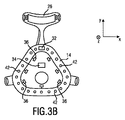
図3A及び3Bは、本発明の患者インタフェース10の第2の実施例を示す。図4は、第2の実施例による信号処理のタイプを示す模式的なブロック図4を示す。図1A及び1Bに示された第1の実施例に加え、患者インタフェース10は更に、第1の圧力センサのセット42(図3B参照)及び第2の圧力センサのセット44(図3A参照)を有しても良い。第1の圧力センサ42は、クッション要素14と患者の顔との間の界面における圧力及び/又は圧力分布についての情報を含む、第1の圧力信号を生成しても良い。第2の圧力センサ44は、例えば枕又はその他の障害物のような外部の物体によって、外部から患者インタフェース10にかけられる力についての情報を含む、第2の圧力信号を生成しても良い。第1の圧力センサ42は、クッション要素14上に又はクッション要素14のなかに配置されても良い。第2の圧力センサ44は好適には、患者インタフェース10の外側面に配置され、例えば(図3Aに示されたように)ヘッドギア20の外側面、又は封止部22の外側面に配置される。
3A and 3B show a second embodiment of the
制御ユニット34は、第2の実施例によれば、変位センサ32により供給される変位信号のみならず、第1及び/又は第2の圧力信号にも基づいて、1つ以上のアクチュエータ36を作動させる。第1の圧力センサ42が、患者インタフェース10と患者の顔との間の界面における圧力分布の変化についての情報を供給し、第2の圧力センサ44が、どこからどの程度の外力が患者インタフェース10に外部から作用しているからの情報を供給するため、このことは封止部22の位置の再調節を更に改善する。
According to the second embodiment, the
当該第2の実施例によれば、入力インタフェースが備えられないことは、更に留意されるべきである。記憶ユニット38は、必ずしも備えられる必要はない。その代わり、患者インタフェース10は、患者インタフェース10が患者12により装着されたときに、患者の顔に対する封止部22の基準位置を自動的に識別する、識別ユニット46(図4参照)を有しても良い。当該識別ユニット46は、検出ユニット30の変位センサ32に接続されても良い。識別ユニット46は好適には、制御ユニット34にも接続される。封止部22の基準位置(最適位置)の自動的な識別は、以下のように実装されても良い。変位センサ32が、患者の顔における特定の目印又は顔の特徴を自動的に識別することを可能とする、例えばCMOSセンサのような光学センサを有しても良い。光学センサ32は例えば、患者12の鼻梁を視覚的に検出する。封止部22の特定の部分が、患者の顔における該鼻梁又はその他の特徴的な点に対して適切に位置決めされるとすぐに、識別ユニット46が制御ユニット34を起動して、変位検出を開始させても良い。換言すれば、識別ユニット46はこのとき、制御ユニット34に対し、患者インタフェース10が現在最適な位置にあることを伝達する。記憶ユニット38が備えられている場合(第1の実施例におけるように)には、このとき識別された基準位置の位置パラメータが、第1の実施例に関連して説明された態様と同様に、基準パラメータとして保存されても良い。次いで光学センサ32が位置の変化を検出すると、制御ユニット34が、封止部22を最適位置に戻すためにアクチュエータ36によりかけられる必要がある力及び方向を算出する。
It should further be noted that according to the second embodiment, no input interface is provided. The
患者インタフェースにかけられる外力、並びに第1及び第2の圧力センサ42、44により供給されるマスク−患者界面における圧力分布に関する付加的な情報が、当該位置再調節算出に含められても良い。第1の圧力センサ42は例えば、患者の顔にかかるクッション要素14のz方向の力を測定しても良く、一方で、x及びy方向は、変位センサ32により測定されても良い。上述したように、いずれの測定も、封止部22の最適位置におけるx、y及びz方向における対応する値/パラメータからの、x、y及びz方向における現在の値の差に関する、算出された値の結果を含む差分を、常に考慮する。
Additional information about the external force applied to the patient interface and the pressure distribution at the mask-patient interface provided by the first and
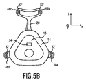
図5は、本発明による患者インタフェース10の第3の実施例を示す。本実施例においては、封止部22の変位は、間接的に検出される。封止部22の位置の再調節も、間接的な態様で実現される。この場合において「間接的」とは、変位が封止部22自体において直接に測定されるのではなく、他の位置で測定されることを意味する。同様に、アクチュエータ36'は、封止部22に直接に接続されてはいない。図5Bに示されるように、検出ユニット30は、マスクがヘッドギアストラップ24a乃至dに接続された位置である、接触点48a乃至dにおいて配置されても良い、幾つかの変位センサ32'を有しても良い。センサ32'はまた、接触点48a乃至dにおける力を測定する、力センサを有しても良い。力センサ32'により測定されるこれらの力又は圧力は、封止部22の変位についての情報を含むため、斯かる力又は圧力センサは、本発明の意味においては変位センサ32'とも解釈されるべきである。アクチュエータ36'は、この場合には好適には、個々のヘッドギアストラップ24a乃至dに接続される。斯くして、1つ以上のアクチュエータ36'は、ヘッドギアストラップ24a乃至dの強度及び/又は長さを個々に調節することにより、患者の顔に対して、封止部22又は少なくともその一部を位置決めするよう構成される。このことは、変位/力センサ32'により感知された信号に応じて、個々のヘッドギアストラップ24a乃至dのそれぞれによりかけられる力を修正することを可能とする。
FIG. 5 shows a third embodiment of the
封止部22が意図せずに移動させられた場合に封止部22を最適な位置に戻すために必要とされる位置の再調節の算出は、第1及び第2の実施例に関連して以上に説明されたものと同一であっても良い。ヘッドギアストラップ24a乃至dの現在の位置又は接触点48a乃至dにおける力は常に、ヘッドギアストラップ24a乃至dの最適な位置又は接触点48a乃至dにおける最適な力分布に対して測定される。前述の2つの実施例に関連して説明されたものと同様に、患者インタフェース10はこのため、基準パラメータを保存するための記憶ユニット38を有しても良い。図5Bには示されていないが、第3の実施例もまた、第1及び/又は第2の圧力センサ42、44(図3A及び3Bに関連して以上に説明されたようなもの)を有しても良い。患者インタフェース10の最適位置における、マスク−患者界面における力分布の値、ヘッドギアストラップ24a乃至d内の力分布、及び変位センサ32'の位置の値が、ここでもまた記憶ユニット38に保存される。次いで、x、y及びz方向における力測定の値が、現在値として記録される。変位/力センサ32は同様に、x及びy方向における位置/力を現在値として記録する。該実施例が、接触点48a乃至dと同じx、y座標に配置された力センサを持たない場合には、最適値及び現在値の双方について、各接触点48a乃至dにおいて推定される力が、(a)種々の力センサと接触点48a乃至dとの間の距離を考慮することによって線形的に、又は(b)封止部22の形状及びフィット状態を考慮に入れて非線形的に、推定される。当該データは次いで、追加値として記憶ユニット38に追加される。各測定値について、最適値として保存された値と現在値との差が、これら値を減算することによって算出されても良い。当該情報は次いで、測定された差として記憶ユニットに保存されても良い。測定された差の値が、力又は変位について起動点を超える場合、制御ユニットが以下のタスクを実行しても良い。(a)差を減少させるための反対力の大きさ及び方向が、制御ユニット34において算出される。(b)制御ユニット34が、ヘッドギアストラップ24a乃至dにおける張力を個別に修正し、封止部22を最適位置に戻すために必要な算出された反対力を生成する。(c)現在値と最適値との測定された差の値が、次いで再算出されても良い。(d)測定された差の値が0又は所定のレベルを下回るまでステップ(a)乃至(c)が「小時間間隔」(FTI)において繰り返されても良い。「通常時間間隔」(RTI)は、標準的な使用の間にセンサ測定値が集められる時間間隔であり、封止部22の位置の再調節の間にセンサ測定値が集められる時間間隔である「小時間間隔」(FTI)よりも長くても良いことは、留意されるべきである。
The calculation of the readjustment of the position required to return the sealing
センサ32'が力センサを有する場合には、各接触点48a乃至dに作用する全体の力は、それぞれx、y及びz方向における力の直交成分で記述されることができる。封止部22がヘッドギアストラップ24a乃至dによって適所に保持される態様に依存して、(a)ヘッドギアストラップ24a乃至dのそれぞれの強度を個別に変更することによって各方向に当該力を修正する機能、(b)アクチュエータ36'によって所与の方向に封止部22を動かす機能、及び(c)アクチュエータ36' によってヘッドギアストラップ24a乃至dを解放することによって顔の封止部22を持ち上げる機能、が存在しても良い。
If sensor 32 'has a force sensor, the total force acting on each
更に、力及び/又は変位センサ32'は、接触点48a乃至dと同じ位置に配置されても良く、これにより、センサ32'により測定される力及び/又は変位が、接触点48a乃至dにおけるものと同じとなるようにしても良いことは、留意されるべきである。代替としては、センサ32'は、接触点48a乃至dとは異なる位置に配置され、接触点48a乃至dにおける実際の力及び/又は変位が、制御ユニット34において導出又は推定されても良い。
Further, the force and / or displacement sensor 32 'may be located at the same location as the contact points 48a-d so that the force and / or displacement measured by the sensor 32' will be at the contact points 48a-d. It should be noted that it may be the same as the one. Alternatively, the sensor 32 'may be located at a different location than the contact points 48a-d, and the actual force and / or displacement at the contact points 48a-d may be derived or estimated at the
更に、ヘッドギアストラップ24a乃至dは、封止部22に直接に接続されても良いことは、留意されるべきである。代替としては、図6A及び6Bにおいて模式的に示されるように、封止部22とヘッドギア20との間に付加的な中間構造50が備えられても良い。
Further, it should be noted that the headgear straps 24a-d may be connected directly to the
図6A及び6Bは、本発明による患者インタフェース10の第4の実施例を示す。当該第4の実施例においては、剛性の又は半剛性のフレーム又は胴体部として実現されても良い、中間構造50が備えられる。該中間構造は、ヘッドギア20を該中間構造に装着するための1つ以上の装着要素52(図6B参照)を有しても良い。この場合には好適には、1つ以上のアクチュエータ36''が、中間構造50と封止部22との間に配置される。1つ以上のアクチュエータ36''は例えば、中間構造50をマスク殻部16に接続しても良い。このことは、中間構造50に対する封止部22の位置の再調節を可能とする。アクチュエータ36''は、ここでもまた、小型の電気機械モータ又は電気活性高分子として実現されても良い。
6A and 6B show a fourth embodiment of the
前述の3つの実施例に比べた当該第4の実施例の主な利点は、封止部22がヘッドギア20から切り離されていることである。換言すれば、中間構造50の固定及び位置の調節は、封止部22の固定及び位置の調節から切り離されている。この場合には、ヘッドギアストラップ24a乃至dは、該中間構造(胴体部)のみを保持し、ヘッドギア20のストラップの緊張度は、マスク−患者の界面における好適な封止を実現することからは切り離される。斯くして、快適さを実現することが容易となる。
A major advantage of the fourth embodiment over the three previous embodiments is that the
封止部22は好適には、電気活性高分子の3つの向きによって、中間構造50に接続される。このことは、マスク−患者の界面における圧力を調節するために、マスクをx、y方向に動かすことのみならず、封止部22をz方向に動かすことも可能とする。制御ユニット34内での算出は、前述した3つの実施例に関連して以上に説明されたものと同じ態様で実現されても良い。
The
封止部22とヘッドギア20との斯かる切り離しにより、封止部22の位置及び圧力はヘッドギアストラップ24a乃至dから切り離され、ストラップの形状及び材質のより広範な選択を可能とする。第4の実施例は更に、付加的な利点を提供する。即ち、患者インタフェース10は更に、患者12の睡眠状態についての情報を含む睡眠状態信号を感知するための睡眠検出センサ54を有しても良い。睡眠検出センサ54は例えば、クッション要素14に配置されても良く、睡眠の間の患者12の心拍の非侵襲的な測定のための光電式容積脈波記録センサ(PPGセンサ)を有しても良い。この場合には、制御ユニット34は、睡眠検出センサ54により感知された睡眠状態信号に基づいて、1つ以上のアクチュエータ36''を作動させるよう構成されても良い。斯くしてアクチュエータ36''は、睡眠段階(例えば覚醒状態、REM睡眠、など)に応じて、患者の顔に対して封止部22を動かすことができる。例えば、過度に長い時間の間、マスク−患者の界面において過度に高い圧力が測定された場合、又は、特定の睡眠段階において圧力による治療が必要とされない場合、マスクが患者12の顔から持ち上げられても良い。ユーザが敏感な皮膚を持ち、赤い跡の形成が防止されるべき場合、このことは特に有利である。例えば、REM睡眠の間は、無呼吸−低呼吸指数(AHI)は幾分か低く、そのため当該睡眠段階においては、封止部22が持ち上げられても良い。これにより、圧力による治療の効果が同じままで、患者インタフェース10の封止部22が患者12の皮膚に接触する総時間が短縮される。
This decoupling of the
最後に、上述した特徴及び種々の実施例を参照しながら説明された構成要素は、複数の態様で組み合わせられ得ることは、留意されるべきである。幾つかの特徴及び構成要素が個々の実施例において視覚化されていないという事実は、これらの特徴及び構成要素が当該実施例と組み合わせられ得ないことを意味するものではない。当業者は、ここで示された特徴及び構成要素の複数の組み合わせが可能であることを理解するであろう。 Finally, it should be noted that the features described above and the components described with reference to the various embodiments can be combined in several ways. The fact that some features and components are not visualized in a particular embodiment does not mean that these features and components cannot be combined with the embodiment. Those skilled in the art will appreciate that multiple combinations of the features and components shown herein are possible.
本発明は図面及び以上の記述において説明され記載されたが、斯かる説明及び記載は説明するもの又は例示的なものであって限定するものではないとみなされるべきであり、本発明は開示された実施例に限定されるものではない。図面、説明及び添付される請求項を読むことにより、請求される本発明を実施化する当業者によって、開示された実施例に対する他の変形が理解され実行され得る。 While the invention has been illustrated and described in the drawings and foregoing description, such explanation and description should be regarded as illustrative or exemplary and not restrictive, the invention is disclosed and illustrated. However, the present invention is not limited to the embodiment. From reading the drawings, description and appended claims, other modifications to the disclosed embodiments can be understood and effected by those skilled in the art in practicing the claimed invention.
請求項において、「有する(comprising)」なる語は他の要素又はステップを除外するものではなく、「1つの(a又はan)」なる不定冠詞は複数を除外するものではない。単一の要素又はその他のユニットが、請求項に列記された幾つかのアイテムの機能を実行しても良い。特定の手段が相互に異なる従属請求項に列挙されているという単なる事実は、これら手段の組み合わせが有利に利用されることができないことを示すものではない。 In the claims, the word "comprising" does not exclude other elements or steps, and the indefinite article "a" or "an" does not exclude a plurality. A single element or other unit may fulfill the functions of several items recited in the claims. The mere fact that certain measures are recited in mutually different dependent claims does not indicate that a combination of these measures cannot be used to advantage.
請求項におけるいずれの参照記号も、請求の範囲を限定するものとして解釈されるべきではない。 Any reference signs in the claims shall not be construed as limiting the claim.
Claims (14)
前記患者インタフェースが前記患者により装着されたときに、前記患者インタフェースと前記患者の顔との間の界面を封止するための封止部と、
前記患者の顔に対する前記封止部の識別された基準位置についての情報を保存するための記憶ユニットと、
前記患者の顔に対する前記封止部の前記識別された基準位置に対する、前記患者の顔に対する前記封止部の変位についての情報を含む、変位信号を生成するための変位センサを含む、検出ユニットと、
前記患者の顔に対して前記封止部の少なくとも一部を位置決めするための1つ以上のアクチュエータと、
前記変位信号に基づいて前記1つ以上のアクチュエータを作動させ、使用の間に前記患者の顔に対する前記封止部の少なくとも一部の位置を調節し、前記封止部の位置を前記識別された基準位置に戻す、制御ユニットと、
を有する患者インタフェース。 A patient interface for providing a flow of breathable gas to a patient, the patient interface comprising:
A seal for sealing an interface between the patient interface and the patient's face when the patient interface is worn by the patient;
A storage unit for storing information about the identified reference position of the seal relative to the patient's face;
For the identified reference position of the sealing portion with respect to the face of the patient, including information about the displacement of the sealing portion with respect to the face of the patient, including a displacement sensor for generating a displacement signal, a detection unit ,
One or more actuators for positioning at least a portion of the seal relative to the patient's face;
Actuating the one or more actuators based on the displacement signal to adjust a position of at least a portion of the seal relative to the patient's face during use , wherein the position of the seal is identified. A control unit for returning to the reference position ,
Patient interface with a.
呼吸可能なガスの流れを生成するための圧力発生器と、
を有する、圧補助システム。 A patient interface according to any one of claims 1 to 13 ,
A pressure generator for producing a flow of breathable gas;
A pressure assist system.
Applications Claiming Priority (3)
| Application Number | Priority Date | Filing Date | Title |
|---|---|---|---|
| EP14156826.1 | 2014-02-26 | ||
| EP14156826 | 2014-02-26 | ||
| PCT/EP2015/052570 WO2015128173A1 (en) | 2014-02-26 | 2015-02-09 | Patient interface with automatic position adjustment |
Publications (3)
| Publication Number | Publication Date |
|---|---|
| JP2017506539A JP2017506539A (en) | 2017-03-09 |
| JP2017506539A5 JP2017506539A5 (en) | 2019-12-12 |
| JP6628731B2 true JP6628731B2 (en) | 2020-01-15 |
Family
ID=50190281
Family Applications (1)
| Application Number | Title | Priority Date | Filing Date |
|---|---|---|---|
| JP2016553666A Expired - Fee Related JP6628731B2 (en) | 2014-02-26 | 2015-02-09 | Patient interface with automatic positioning |
Country Status (5)
| Country | Link |
|---|---|
| US (1) | US10471226B2 (en) |
| EP (1) | EP3110487B1 (en) |
| JP (1) | JP6628731B2 (en) |
| CN (1) | CN106061536B (en) |
| WO (1) | WO2015128173A1 (en) |
Families Citing this family (19)
| Publication number | Priority date | Publication date | Assignee | Title |
|---|---|---|---|---|
| WO2015196255A1 (en) * | 2014-06-27 | 2015-12-30 | Resmed Limited | Auto-fit mask |
| SG11201707578TA (en) | 2015-03-31 | 2017-10-30 | Fisher & Paykel Healthcare Ltd | A user interface and system for supplying gases to an airway |
| US10310481B2 (en) | 2015-10-07 | 2019-06-04 | International Business Machines Corporation | Dynamic position control for electronic components |
| CA3019203A1 (en) | 2016-03-24 | 2017-09-28 | Trudell Medical International | Respiratory care system with electronic indicator |
| US10359806B2 (en) * | 2016-03-28 | 2019-07-23 | Sony Interactive Entertainment Inc. | Pressure sensing to identify fitness and comfort of virtual reality headset |
| CA3020577C (en) * | 2016-05-19 | 2023-08-01 | Trudell Medical International | Smart valved holding chamber |
| CA3028604C (en) | 2016-07-08 | 2023-12-05 | Trudell Medical International | Smart oscillating positive expiratory pressure device |
| US10488830B2 (en) * | 2016-08-10 | 2019-11-26 | Intel Corporation | Automatic adjustment of head mounted display straps |
| GB2567998B (en) | 2016-08-11 | 2022-07-20 | Fisher & Paykel Healthcare Ltd | A collapsible conduit, patient interface and headgear connector |
| DE202017007545U1 (en) | 2016-12-09 | 2022-09-01 | Trudell Medical International | Intelligent nebulizer |
| WO2018174879A1 (en) * | 2017-03-23 | 2018-09-27 | Hewlett-Packard Development Company, L.P. | Strap adjustments via sensors |
| US11666801B2 (en) | 2018-01-04 | 2023-06-06 | Trudell Medical International | Smart oscillating positive expiratory pressure device |
| JP7427660B2 (en) | 2018-06-04 | 2024-02-05 | トゥルーデル メディカル インターナショナル | Holding chamber with smart valve |
| EP3769636A1 (en) | 2019-07-24 | 2021-01-27 | 3M Innovative Properties Company | Article comprising an elongated pressure sensitive component |
| WO2021038467A1 (en) | 2019-08-27 | 2021-03-04 | Trudell Medical International | Smart oscillating positive expiratory pressure device |
| US11029525B2 (en) * | 2019-12-19 | 2021-06-08 | Intel Corporation | Automatic sensor positioning for biometric sensing |
| WO2021256998A1 (en) * | 2020-06-16 | 2021-12-23 | National University Of Singapore | A face mask |
| EP4262191A1 (en) * | 2020-12-11 | 2023-10-18 | JVCKenwood Corporation | Head-mounted display and adjusting method therefor |
| CN114432567B (en) * | 2022-04-12 | 2022-07-08 | 深圳市心流科技有限公司 | Automatic separation control method and device for sleep-assisting equipment, sleep-assisting equipment and storage medium |
Family Cites Families (15)
| Publication number | Priority date | Publication date | Assignee | Title |
|---|---|---|---|---|
| US7204250B1 (en) * | 1999-12-16 | 2007-04-17 | Compumedics Limited | Bio-mask |
| US7025730B2 (en) * | 2003-01-10 | 2006-04-11 | Medtronic, Inc. | System and method for automatically monitoring and delivering therapy for sleep-related disordered breathing |
| US7743768B2 (en) | 2005-12-20 | 2010-06-29 | Ric Investments, Llc | Patient interface device with dampening cushion |
| JP2010131091A (en) * | 2008-12-03 | 2010-06-17 | Niigata Univ | System, method and program for supporting mask shape determination |
| EP2445563A4 (en) | 2009-06-24 | 2016-03-23 | Resmed Ltd | Adjustable mask system and related methods |
| NZ625053A (en) | 2009-11-16 | 2015-11-27 | Resmed Ltd | Methods and apparatus for adaptable pressure treatment of sleep disordered breathing |
| RU2556565C2 (en) * | 2009-12-19 | 2015-07-10 | Конинклейке Филипс Электроникс Н.В. | Pressure maintenance system with mask adjustment feedback display |
| US8336546B2 (en) * | 2011-02-08 | 2012-12-25 | Hancock Medical, Inc. | Positive airway pressure system with head control |
| WO2012135420A2 (en) * | 2011-04-01 | 2012-10-04 | Unifersity Of Florida Research Foundation, Inc. | Over-expression of hadh-dependent oxidoreductase (fuco) for increasing furfural or 5-hydroxymethylfurfural tolerance |
| EP2755710B1 (en) * | 2011-09-13 | 2018-05-23 | ResMed Limited | Vent arrangement for respiratory mask |
| US9168347B2 (en) * | 2011-11-16 | 2015-10-27 | International Business Machines Corporation | Managing an active strap system for a face mask |
| CN103648567B (en) | 2012-03-09 | 2016-11-23 | 汉考克医药公司 | There is the positive airway pressure system that head position controls |
| US10046131B2 (en) * | 2012-06-08 | 2018-08-14 | Koninklijke Philips N.V. | Patient interface with cushion for red mark prevention |
| US20150224275A1 (en) * | 2012-08-09 | 2015-08-13 | Sander Theodoor Pastoor | Customisation or adjustment of patient interfaces |
| CN203208491U (en) * | 2013-05-03 | 2013-09-25 | 浙江大学 | Adjustable breathing mask |
-
2015
- 2015-02-09 CN CN201580010466.2A patent/CN106061536B/en not_active Expired - Fee Related
- 2015-02-09 WO PCT/EP2015/052570 patent/WO2015128173A1/en active Application Filing
- 2015-02-09 EP EP15704978.4A patent/EP3110487B1/en active Active
- 2015-02-09 US US15/120,870 patent/US10471226B2/en active Active
- 2015-02-09 JP JP2016553666A patent/JP6628731B2/en not_active Expired - Fee Related
Also Published As
| Publication number | Publication date |
|---|---|
| US20160361512A1 (en) | 2016-12-15 |
| EP3110487B1 (en) | 2019-11-20 |
| EP3110487A1 (en) | 2017-01-04 |
| CN106061536B (en) | 2020-05-05 |
| WO2015128173A1 (en) | 2015-09-03 |
| US10471226B2 (en) | 2019-11-12 |
| JP2017506539A (en) | 2017-03-09 |
| CN106061536A (en) | 2016-10-26 |
Similar Documents
| Publication | Publication Date | Title |
|---|---|---|
| JP6628731B2 (en) | Patient interface with automatic positioning | |
| JP7267371B2 (en) | patient interface | |
| CN114404764B (en) | Adjustable headgear tube for patient interface | |
| JP6720186B2 (en) | Patient interface device | |
| JP6196214B2 (en) | PAP system | |
| US5884625A (en) | Oral appliance for delivering gas to the retroglossal area | |
| JP2021166849A (en) | Patient interface with seal-forming structure having varying thickness | |
| CN106537396B (en) | System and method for providing personalized advice to a patient | |
| US10980963B1 (en) | Cloth respiratory mask | |
| CN112292171A (en) | Patient interface | |
| CN107614044A (en) | With the patient interface for sealing the anti-spray piece for forming part | |
| JP2012519017A (en) | Oral continuous positive airway pressure (CPAP) interface | |
| EP2996753B1 (en) | Auto-feedback valve for a sleep apnea device | |
| KR100858668B1 (en) | Apparatus for preventing from sleeping respiratory obstruction and method using the same | |
| JP6002251B2 (en) | Positive airway pressure system with head position control | |
| CN112041013A (en) | Patient interface | |
| US20170304576A1 (en) | Strap member for a patient interface | |
| JP2018102349A (en) | Mask attachment, method for manufacturing mask attachment, and method for mounting noninvasive positive pressure ventilation mask | |
| US20150151068A1 (en) | Patient interface device | |
| JP6233847B2 (en) | Airway securing device | |
| US20220331065A1 (en) | Sleep apnea and anti-snoring system | |
| JPH11151297A (en) | Nose mask for respiration | |
| KR102499894B1 (en) | Mandibular advancement device | |
| CN215916085U (en) | Patient interface | |
| WO2023129154A1 (en) | Sleep apnea and anti-snoring system |
Legal Events
| Date | Code | Title | Description |
|---|---|---|---|
| RD04 | Notification of resignation of power of attorney |
Free format text: JAPANESE INTERMEDIATE CODE: A7424 Effective date: 20170214 |
|
| A521 | Request for written amendment filed |
Free format text: JAPANESE INTERMEDIATE CODE: A523 Effective date: 20171211 |
|
| A621 | Written request for application examination |
Free format text: JAPANESE INTERMEDIATE CODE: A621 Effective date: 20171211 |
|
| A977 | Report on retrieval |
Free format text: JAPANESE INTERMEDIATE CODE: A971007 Effective date: 20181102 |
|
| A131 | Notification of reasons for refusal |
Free format text: JAPANESE INTERMEDIATE CODE: A131 Effective date: 20181113 |
|
| A601 | Written request for extension of time |
Free format text: JAPANESE INTERMEDIATE CODE: A601 Effective date: 20190212 |
|
| A521 | Request for written amendment filed |
Free format text: JAPANESE INTERMEDIATE CODE: A523 Effective date: 20190422 |
|
| A02 | Decision of refusal |
Free format text: JAPANESE INTERMEDIATE CODE: A02 Effective date: 20190702 |
|
| A524 | Written submission of copy of amendment under article 19 pct |
Free format text: JAPANESE INTERMEDIATE CODE: A524 Effective date: 20191023 |
|
| A911 | Transfer to examiner for re-examination before appeal (zenchi) |
Free format text: JAPANESE INTERMEDIATE CODE: A911 Effective date: 20191031 |
|
| TRDD | Decision of grant or rejection written | ||
| A01 | Written decision to grant a patent or to grant a registration (utility model) |
Free format text: JAPANESE INTERMEDIATE CODE: A01 Effective date: 20191126 |
|
| A61 | First payment of annual fees (during grant procedure) |
Free format text: JAPANESE INTERMEDIATE CODE: A61 Effective date: 20191203 |
|
| R150 | Certificate of patent or registration of utility model |
Ref document number: 6628731 Country of ref document: JP Free format text: JAPANESE INTERMEDIATE CODE: R150 |
|
| LAPS | Cancellation because of no payment of annual fees |