JP6628191B2 - Gaming machine - Google Patents

Gaming machine Download PDF

Info

Publication number
JP6628191B2
JP6628191B2 JP2017001536A JP2017001536A JP6628191B2 JP 6628191 B2 JP6628191 B2 JP 6628191B2 JP 2017001536 A JP2017001536 A JP 2017001536A JP 2017001536 A JP2017001536 A JP 2017001536A JP 6628191 B2 JP6628191 B2 JP 6628191B2
Authority
JP
Japan
Prior art keywords
movable member
displaced
movable
effect
relay
Prior art date
Legal status (The legal status is an assumption and is not a legal conclusion. Google has not performed a legal analysis and makes no representation as to the accuracy of the status listed.)
Active
Application number
JP2017001536A
Other languages
Japanese (ja)
Other versions
JP2017064459A (en
JP2017064459A5 (en
Inventor
真 宮永
真 宮永
忠 稲垣
忠 稲垣
Original Assignee
株式会社サンセイアールアンドディ
Priority date (The priority date is an assumption and is not a legal conclusion. Google has not performed a legal analysis and makes no representation as to the accuracy of the date listed.)
Filing date
Publication date
Application filed by 株式会社サンセイアールアンドディ filed Critical 株式会社サンセイアールアンドディ
Priority to JP2017001536A priority Critical patent/JP6628191B2/en
Publication of JP2017064459A publication Critical patent/JP2017064459A/en
Publication of JP2017064459A5 publication Critical patent/JP2017064459A5/ja
Application granted granted Critical
Publication of JP6628191B2 publication Critical patent/JP6628191B2/en
Active legal-status Critical Current
Anticipated expiration legal-status Critical

Links

Images

Description

本発明は、駆動源の動力によって駆動する可動部材を備えた遊技機に関する。   The present invention relates to a gaming machine having a movable member driven by the power of a drive source.

多くの遊技機には、演出効果を高めるための可動部材(いわゆる役物)が搭載されている。例えば下記特許文献1等に記載されるように、一つの駆動源で複数の可動部材を駆動させ、演出効果を高めるようにした遊技機が種々知られている。このように、駆動源を増加させることなく複数の可動部材を動作させるようにするだけでなく、当該複数の可動部材の動作態様を面白みのあるもの(従来にないもの)とすることで、遊技の趣向性を高めることが求められる。   Many gaming machines are equipped with a movable member (so-called accessory) for enhancing the effect of the effect. For example, as described in Patent Literature 1 and the like, various gaming machines have been known in which a plurality of movable members are driven by a single drive source so as to enhance an effect. In this way, not only can the plurality of movable members be operated without increasing the number of drive sources, but also the operating modes of the plurality of movable members can be interesting (unconventional ones), thereby providing a game. It is required to enhance the taste.

特開2011−255235号公報JP 2011-255235 A

本発明は、複数の可動部材を備えた遊技機において、当該複数の可動部材の動作態様を面白みのあるものとすることで、遊技(演出)の趣向性の向上を図ることを目的とする。   SUMMARY OF THE INVENTION An object of the present invention is to provide a gaming machine having a plurality of movable members, in which the operation modes of the plurality of movable members are interesting, thereby improving the interest of the game (production).

上記課題を解決するためになされた本発明にかかる遊技機は、駆動源と、遊技者に視認される部材であって、前記駆動源の動力により変位可能な演出部材と、遊技者に視認される部材であって、前記演出部材に対して一方端側が回転自在に支持された第一可動部材および第二可動部材と、を備え、前記駆動源の動力が前記演出部材に伝達されることで、当該演出部材が、それに支持された前記第一可動部材および前記第二可動部材との相対位置を変化させずに変位する状態と、前記駆動源の動力が前記演出部材に伝達されずに前記第一可動部材および前記第二可動部材の他方端側に伝達されることで、当該演出部材が変位しない状態で、当該第一可動部材および第二可動部材の両方が当該演出部材に支持された一方端側を支点として回動するとともに、当該第一可動部材および第二可動部材の他方端側が互いに近づく方向または離れる方向に変位する状態と、が切り替えられることを特徴とする。 A gaming machine according to the present invention made in order to solve the above problem is a driving source, a member visually recognized by a player, a rendering member displaceable by the power of the driving source, and a player visually recognized by a player. A first movable member and a second movable member, one end of which is rotatably supported with respect to the effect member, and the power of the drive source is transmitted to the effect member. A state in which the effecting member is displaced without changing the relative position between the first movable member and the second movable member supported thereon, and the power of the drive source is not transmitted to the effecting member, By being transmitted to the other end side of the first movable member and the second movable member, both the first movable member and the second movable member are supported by the rendering member in a state where the rendering member is not displaced. Rotate around one end as a fulcrum Together, characterized in that the state of the other end side of the first movable member and second movable member is displaced in a direction in which the direction or away from approaching each other, is switched.

本発明によれば、当該複数の可動部材の動作態様を面白みのあるものとなり、遊技(演出)の趣向性を向上させることが可能である。   According to the present invention, the operation mode of the plurality of movable members becomes interesting, and it is possible to improve the interest of the game (production).

本発明の一実施形態にかかる遊技機の正面図であり、演出装置が原位置に位置した状態を示したものである(発射装置(発射ハンドル)等公知の部材は省略)。1 is a front view of a gaming machine according to an embodiment of the present invention, showing a state in which an effect device is located at an original position (a known member such as a firing device (a firing handle) is omitted). センターベースおよびそれに固定された演出装置の正面図(遊技盤を取り外した状態の正面図)であって、演出部材が原位置に位置し、可動部材が第一状態にあるものを示した図である。FIG. 2 is a front view of the center base and the effect device fixed thereto (a front view with the game board removed), showing a state in which the effect member is located at the original position and the movable member is in the first state. is there. センターベースおよびそれに固定された演出装置の正面図(遊技盤を取り外した状態の正面図)であって、演出部材が演出位置に位置し、可動部材が第二状態にあるものを示した図である。FIG. 4 is a front view of the center base and the effect device fixed thereto (a front view with the game board removed), showing the effect member positioned at the effect position and the movable member in the second state. is there. 演出装置の外観図である。It is an external view of a production device. 演出装置の正面図であって、可動部材が第一状態にあるものを示した図である。It is the front view of a production device which showed the movable member in a 1st state. 演出装置の正面図であって、可動部材が第二状態にあるものを示した図である。It is a front view of the production device, and is a diagram showing that the movable member is in the second state. 演出部材を取り外した状態にある演出装置の外観図であって、駆動源から演出部材や可動部材に至る動力伝達機構を説明するための図である。It is an external view of the production device in the state where the production member was removed, and is a view for explaining a power transmission mechanism from a drive source to the production member and the movable member. 演出装置の背面図であって、可動部材が第一状態にあるものを示した図である。It is a rear view of the production device, and is a diagram showing the movable member in the first state. 演出装置の背面図であって、可動部材が第二状態にあるものを示した図である。It is a rear view of the production device, and is a diagram showing the movable member in the second state. 前後方向における光源、演出部材、可動部材の位置関係を説明するための模式図である。It is a schematic diagram for demonstrating the positional relationship of a light source, a production member, and a movable member in the front-back direction.

以下、本発明にかかる実施形態について図面を参照して詳細に説明する。なお、以下の説明における平面方向とは遊技領域902に沿う(平行な)方向を、前後方向とは遊技領域902に直交する方向(遊技者側を前、その反対側を後とする)を、左右方向(幅方向)とは図1の左右方向を、上下方向とは図1の上下方向をいうものとする。   Hereinafter, embodiments of the present invention will be described in detail with reference to the drawings. In the following description, a plane direction is a direction (parallel) along the game area 902, and a front-rear direction is a direction orthogonal to the game area 902 (the player side is the front, and the opposite side is the back). The left-right direction (width direction) refers to the left-right direction in FIG. 1, and the up-down direction refers to the up-down direction in FIG.

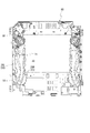
まず、図1を参照して遊技機1の全体構成について簡単に説明する。遊技機1は遊技盤90を備える。遊技盤90は、ほぼ正方形の合板により成形されており、発射装置の操作によって発射された遊技球を遊技領域902に案内する金属製の薄板からなる帯状のガイドレール903が略円弧形状となるように設けられている。   First, the overall configuration of the gaming machine 1 will be briefly described with reference to FIG. The gaming machine 1 includes a gaming board 90. The game board 90 is formed of a substantially square plywood, and a strip-shaped guide rail 903 made of a thin metal plate for guiding a game ball fired by the operation of the firing device to the game area 902 has a substantially arc shape. It is provided in.

遊技領域902には、表示装置91、第一始動入賞口904、第二始動入賞口905、大入賞口906、アウト口907などが設けられている。表示装置91は、例えば液晶表示装置が用いられ、表示装置91の表示画面(表示部)において特別図柄や普通図柄等が表示される。かかる表示装置91の表示画面は、遊技盤90に形成された開口901を通じて視認可能である。   In the game area 902, a display device 91, a first starting winning opening 904, a second starting winning opening 905, a big winning opening 906, an out opening 907, and the like are provided. As the display device 91, for example, a liquid crystal display device is used, and a special symbol, a normal symbol, and the like are displayed on a display screen (display unit) of the display device 91. The display screen of the display device 91 is visible through an opening 901 formed in the game board 90.

また、遊技領域902には、流下する遊技球が衝突することにより遊技球の流下態様に変化を与える障害物としての遊技釘が複数設けられている。遊技領域902を流下する遊技球は、遊技釘に衝突したときの条件に応じて様々な態様に変化する。   Further, in the game area 902, a plurality of game nails are provided as obstacles that change the flow state of the game balls when the game balls flow down. The game ball flowing down the game area 902 changes in various modes according to the conditions at the time of collision with the game nail.

このような遊技機1では、発射装置(図示省略)を操作することにより遊技領域902に向けて遊技球を発射する。遊技領域902を流下する遊技球が、始動入賞口904、905や大入賞口906等の入賞口に入賞すると、所定の数の賞球が払出装置により払い出される。その他、大当たりの抽選方法や演出等は、公知の遊技機と同様のものが適用できるため、説明は省略する。なお、本実施形態にかかる遊技機1は、いわゆるぱちんこ遊技機であるが、以下で説明する構成は、スロットマシン等、他の種類の遊技機にも適用可能である。   In such a gaming machine 1, a game ball is fired toward the game area 902 by operating a firing device (not shown). When a game ball flowing down the game area 902 wins a prize hole such as a start prize hole 904, 905 or a large prize hole 906, a predetermined number of prize balls are paid out by a payout device. In addition, as for the jackpot lottery method and effects, the same ones as those of known gaming machines can be applied, and the description is omitted. The gaming machine 1 according to the present embodiment is a so-called pachinko gaming machine, but the configuration described below can be applied to other types of gaming machines such as a slot machine.

以下、本実施形態にかかる遊技機1が備える演出装置1aについて、図面を参照して詳細に説明する。なお、本実施形態では、センターベース80の左側および右側に一つずつ演出装置1aが設けられている(図1〜図3参照)が、以下、左側に設けられた演出装置1aを説明し、右側に設けられた演出装置1aの基本的な構造は左側に設けられたものと同じである(左右反対である)ため、説明は省略する。図4〜図9に示す演出装置1aは、左側に設けられたものである。本実施形態にかかる演出装置1aは、演出部材10、可動部材20、動力伝達部材40(本発明におけるスライド部材に相当する)を備える。   Hereinafter, the effect device 1a included in the gaming machine 1 according to the present embodiment will be described in detail with reference to the drawings. In the present embodiment, the effect devices 1a are provided one by one on the left and right sides of the center base 80 (see FIGS. 1 to 3). However, the effect devices 1a provided on the left side will be described below. Since the basic structure of the effect device 1a provided on the right side is the same as that provided on the left side (the left and right sides are reversed), the description is omitted. The effect device 1a shown in FIGS. 4 to 9 is provided on the left side. The effect device 1a according to the present embodiment includes an effect member 10, a movable member 20, and a power transmission member 40 (corresponding to a slide member in the present invention).

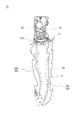
演出部材10は、「剣」を模した形状を有する細長い部材である。一方、可動部材20は、「炎」を模した形状を有する細長い部材である(図4〜図6等参照)。本実施形態では、左可動部材20L(本発明における第一可動部材に相当する)、右可動部材20R(本発明における第二可動部材に相当する)という二つの可動部材20が設けられており、両可動部材20は、演出部材10よりも後方に位置する。前後方向における左可動部材20Lと右可動部材20Rの位置は略同じである。左可動部材20Lおよび右可動部材20Rそれぞれの先端側(本実施形態では原位置に位置するときにおける下側)には、貫通孔である被支持孔(左被支持孔21、右被支持孔21R)が形成されている(図7等参照)。当該各被支持孔内には、演出部材10の先端側(本実施形態では原位置に位置するときにおける下側)に設けられた支持突起(左支持突起11Lおよび右支持突起11R)が嵌まり込んでいる。つまり、左可動部材20Lは、左被支持孔21に係合する左支持突起11Lを支点として回動することが可能であり、右可動部材20Rは、右被支持孔21Rに係合する右支持突起11Rを支点として回動することが可能である(図5〜図7等参照)。   The effect member 10 is an elongated member having a shape imitating a “sword”. On the other hand, the movable member 20 is an elongated member having a shape imitating “flame” (see FIGS. 4 to 6 and the like). In the present embodiment, two movable members 20 are provided, a left movable member 20L (corresponding to a first movable member in the present invention) and a right movable member 20R (corresponding to a second movable member in the present invention). Both movable members 20 are located behind rendering member 10. The positions of the left movable member 20L and the right movable member 20R in the front-back direction are substantially the same. At the distal ends (the lower side when located at the original position in the present embodiment) of the left movable member 20L and the right movable member 20R, the supported holes (the left supported hole 21 and the right supported hole 21R) which are through holes are provided. ) Is formed (see FIG. 7 and the like). In each of the supported holes, support protrusions (left support protrusion 11L and right support protrusion 11R) provided on the distal end side (lower side when located at the original position in the present embodiment) of effect member 10 are fitted. It is crowded. That is, the left movable member 20L can rotate about the left support projection 11L engaged with the left supported hole 21 as a fulcrum, and the right movable member 20R can rotate with the right support engaged with the right supported hole 21R. It is possible to rotate around the projection 11R as a fulcrum (see FIGS. 5 to 7 and the like).

演出部材10の基端側には、後方に向かって突出する突起である被誘導突起15が形成されている。当該被誘導突起15は、遊技盤90の後方に設けられたセンターベース80に固定される板部材81に形成された誘導溝811に嵌まり込んでいる(図3、図8、図9等参照)。被誘導突起15は誘導溝811内をスライドすることができる。誘導溝811は円弧形状の溝である。詳細を後述するように、被誘導突起15を有する演出部材10は、当該円弧状の誘導溝811に沿うように変位する。   On the base end side of the effect member 10, a guided protrusion 15 which is a protrusion protruding rearward is formed. The guided protrusion 15 is fitted in a guide groove 811 formed in a plate member 81 fixed to a center base 80 provided behind the game board 90 (see FIGS. 3, 8, 9 and the like). ). The guided projection 15 can slide in the guiding groove 811. The guide groove 811 is an arc-shaped groove. As will be described in detail later, the rendering member 10 having the guided projection 15 is displaced along the arc-shaped guiding groove 811.

かかる演出部材10および可動部材20に対し、図7に詳細を示す動力伝達部材40が変位自在に支持されている。動力伝達部材40には、伝達軸係合孔41、第一被係合孔42、第二被係合孔43、伝達突起44(本発明における係合部に相当する)、および伝達歯竿45(本発明におけるラック部に相当する)が形成されている。   A power transmission member 40 shown in detail in FIG. 7 is movably supported by the effect member 10 and the movable member 20. The power transmission member 40 includes a transmission shaft engaging hole 41, a first engaged hole 42, a second engaged hole 43, a transmission protrusion 44 (corresponding to an engagement portion in the present invention), and a transmission tooth rod 45. (Corresponding to the rack part in the present invention).

伝達軸係合孔41は、駆動源50(本実施形態ではモータ)の動力によって回転する伝達歯車51の伝達軸511が係合する孔である。本実施形態における伝達軸係合孔41は貫通孔であるが貫通孔である必要はない。当該伝達軸係合孔41の内面が伝達軸511に押されることにより、動力伝達部材40が変位する。伝達軸係合孔41の形状は、演出部材10および可動部材20が後述するように動作するよう設定される。   The transmission shaft engaging hole 41 is a hole in which the transmission shaft 511 of the transmission gear 51 rotated by the power of the drive source 50 (motor in the present embodiment) is engaged. The transmission shaft engaging hole 41 in the present embodiment is a through hole, but need not be a through hole. When the inner surface of the transmission shaft engaging hole 41 is pushed by the transmission shaft 511, the power transmission member 40 is displaced. The shape of the transmission shaft engaging hole 41 is set so that the effect member 10 and the movable member 20 operate as described later.

第一被係合孔42および第二被係合孔43は、演出部材10に設けられ係合突起が嵌まり込む細長い孔である。本実施形態における第一被係合孔42および第二被係合孔43は貫通孔であるが貫通孔である必要はない。第一被係合孔42には第一係合突起12が、第二被係合孔43には第二係合突起13が嵌まり込んでいる。第一被係合孔42の幅と第一係合突起12の直径、第二被係合孔43の幅と第二係合突起13の直径はほぼ同じ(わずかに係合突起の直径の方が小さい)であり、各係合突起は、各被係合孔の長手方向に変位する(被係合孔に対する相対位置を変位させる)ことは可能であるが、各被係合孔の幅方向にはほとんど変位することができない。   The first engaged hole 42 and the second engaged hole 43 are elongated holes provided in the rendering member 10 and into which the engagement protrusions are fitted. The first engaged hole 42 and the second engaged hole 43 in the present embodiment are through holes, but need not be through holes. The first engagement protrusion 12 is fitted in the first engaged hole 42, and the second engagement protrusion 13 is fitted in the second engaged hole 43. The width of the first engaged hole 42 and the diameter of the first engaging projection 12 and the width of the second engaged hole 43 and the diameter of the second engaging projection 13 are substantially the same (slightly smaller than the diameter of the engaging projection). Is small), and each engaging projection can be displaced in the longitudinal direction of each engaged hole (displaced a relative position with respect to the engaged hole), but can be displaced in the width direction of each engaged hole. Can hardly be displaced.

伝達突起44は、一方の可動部材20(本実施形態では左可動部材20L)側に設けられた左中継部材60L(本発明における第一中継部材に相当する)に係合している。左中継部材60Lは、演出部材10に回動自在に支持されており、当該支点の一方側に長孔である左第一中継孔61Lが、他方側に長孔である左第二中継孔62Lが形成されている。伝達突起44は、左第一中継孔61Lに係合している。左第一中継孔61Lの幅と伝達突起44の直径はほぼ同じ(わずかに伝達突起44の直径の方が小さい)であり、伝達突起44は、左第一中継孔61Lの長手方向に変位する(左第一中継孔61Lに対する相対位置を変位させる)ことは可能であるが、左第一中継孔61Lの幅方向にはほとんど変位することができない。   The transmission protrusion 44 is engaged with a left relay member 60L (corresponding to a first relay member in the present invention) provided on one of the movable members 20 (the left movable member 20L in the present embodiment). The left relay member 60L is rotatably supported by the effect member 10, and the left first relay hole 61L which is a long hole on one side of the fulcrum and the left second relay hole 62L which is a long hole on the other side. Is formed. The transmission protrusion 44 is engaged with the left first relay hole 61L. The width of the left first relay hole 61L and the diameter of the transmission protrusion 44 are substantially the same (the diameter of the transmission protrusion 44 is slightly smaller), and the transmission protrusion 44 is displaced in the longitudinal direction of the left first relay hole 61L. (It is possible to displace the relative position with respect to the left first relay hole 61L), but it is hardly displaced in the width direction of the left first relay hole 61L.

また、左第二中継孔62Lには、左可動部材20Lの基端側(本実施形態では原位置に位置するときにおける上側)に設けられた左作動突起22Lが係合している。左第二中継孔62Lの幅と左作動突起22Lの直径はほぼ同じ(わずかに左作動突起22Lの直径の方が小さい)であり、左作動突起22Lは、左第二中継孔62Lの長手方向に変位する(左第二中継孔62Lに対する相対位置を変位させる)ことは可能であるが、左第二中継孔62Lの幅方向にはほとんど変位することができない。   A left operating projection 22L provided on the base end side of the left movable member 20L (upper side when located at the original position in this embodiment) is engaged with the left second relay hole 62L. The width of the left second relay hole 62L and the diameter of the left operating projection 22L are substantially the same (slightly smaller in diameter than the left operating projection 22L), and the left operating projection 22L is in the longitudinal direction of the left second relay hole 62L. (The relative position with respect to the left second relay hole 62L can be displaced), but can hardly be displaced in the width direction of the left second relay hole 62L.

伝達歯竿45は、動力伝達部材40の側面に形成され、他方の可動部材20(本実施形態では右可動部材20R)側に設けられた右中継部材60R(本発明における第二中継部材に相当する)に係合している。右中継部材60Rは、左中継部材60Lと同様に演出部材10に回動自在に支持されている。右中継部材60Rの一方側(動力伝達部材40側)には、その回動中心と中心を同じにする中継歯車部61R(本発明における歯車部に相当する)が、他方側には、長孔である右中継孔62Rが形成されている。伝達歯竿45は、右中継部材60Rの中継歯車部61Rに噛み合っている。つまり、伝達歯竿45が変位することで、それに噛み合う中継歯車部61R(右中継部材60R)が回動することとなる。   The transmission tooth rod 45 is formed on a side surface of the power transmission member 40, and a right relay member 60R (corresponding to a second relay member in the present invention) provided on the other movable member 20 (the right movable member 20R in the present embodiment). To). The right relay member 60R is rotatably supported by the effect member 10 similarly to the left relay member 60L. On one side (the power transmission member 40 side) of the right relay member 60R, there is provided a relay gear portion 61R (corresponding to a gear portion in the present invention) having the same rotation center as its center, and on the other side, a long hole. The right relay hole 62R is formed. The transmission tooth pole 45 meshes with the relay gear portion 61R of the right relay member 60R. That is, when the transmission tooth pole 45 is displaced, the relay gear 61R (the right relay member 60R) that meshes with the transmission tooth rod 45 rotates.

また、右中継孔62Rには、右可動部材20Rの基端側(本実施形態では原位置に位置するときにおける上側)に設けられた右作動突起22Rが係合している。右中継孔62Rの幅と右作動突起22Rの直径はほぼ同じ(わずかに右作動突起22Rの直径の方が小さい)であり、右作動突起22Rは、右中継孔62Rの長手方向に変位する(右中継孔62Rに対する相対位置を変位させる)ことは可能であるが、右中継孔62Rの幅方向にはほとんど変位することができない。   The right relay hole 62R is engaged with a right operating projection 22R provided on the base end side of the right movable member 20R (upper side when located at the original position in the present embodiment). The width of the right relay hole 62R and the diameter of the right operating projection 22R are substantially the same (slightly smaller in diameter than the right operating projection 22R), and the right operating projection 22R is displaced in the longitudinal direction of the right relay hole 62R ( It is possible to displace the relative position with respect to the right relay hole 62R), but it is hardly displaceable in the width direction of the right relay hole 62R.

本実施形態では、可動部材20よりもさらに後方に光源30が設けられている(図10等参照)。具体的には、可動部材20よりもさらに後方に配置された基板31(基板31の前面)上に複数の光源30が実装されている。各光源30は、前方に向かって光を出射する。本実施形態における光源30はLEDである。   In the present embodiment, the light source 30 is provided further behind the movable member 20 (see FIG. 10 and the like). Specifically, a plurality of light sources 30 are mounted on a substrate 31 (the front surface of the substrate 31) disposed further behind the movable member 20. Each light source 30 emits light forward. The light source 30 in the present embodiment is an LED.

演出部材10および可動部材20は、上記光源30から出射された光を透過させる光透過部を有する。演出部材10は、少なくともその幅方向両側に第一光透過部14を有する(「剣」の「刃」の部分が第一光透過部14となっている)(図4〜図6等参照)。本実施形態における第一光透過部14は無色透明である。第一光透過部14以外の箇所(例えば幅方向中央側の部分である遮蔽部141)は、光を透過させない材料で形成されている。   The effect member 10 and the movable member 20 have a light transmitting portion that transmits light emitted from the light source 30. The effecting member 10 has the first light transmitting portions 14 at least on both sides in the width direction (the "blade" portion of the "sword" is the first light transmitting portion 14) (see FIGS. 4 to 6 and the like). . The first light transmitting section 14 in the present embodiment is colorless and transparent. A portion other than the first light transmitting portion 14 (for example, the shielding portion 141 at the center in the width direction) is formed of a material that does not transmit light.

一方、可動部材20(左可動部材20Lおよび右可動部材20R)は、第二光透過部を有する。本実施形態では、左可動部材20Lおよび右可動部材20Rの略全体が光透過性の材料で形成されている(略全体が第二光透過部である)。本実施形態における第二光透過部は有色(本実施形態では青)透明である。   On the other hand, the movable member 20 (the left movable member 20L and the right movable member 20R) has a second light transmitting portion. In the present embodiment, substantially the entirety of the left movable member 20L and the right movable member 20R is formed of a light transmissive material (substantially the entirety is a second light transmitting portion). The second light transmitting portion in the present embodiment is colored (blue in the present embodiment) and transparent.

このように構成される演出装置1aの動作(作用)について以下説明する。原位置に位置する演出部材10および可動部材20は、上下方向に沿うようにして位置する。この際、演出部材10と可動部材20(左可動部材20Lおよび右可動部材20R)は、前後方向において少なくとも一部が重なっている。つまり、可動部材20の少なくとも一部は、演出部材10に覆われた状態にある(図5等参照)。   The operation (action) of the effect device 1a thus configured will be described below. The effecting member 10 and the movable member 20 located at the original position are located along the vertical direction. At this time, the effect member 10 and the movable member 20 (the left movable member 20L and the right movable member 20R) at least partially overlap in the front-rear direction. That is, at least a part of the movable member 20 is in a state of being covered by the rendering member 10 (see FIG. 5 and the like).

演出部材10および可動部材20が位置した状態から、駆動源50を一方に回転させる(正転させる)と、演出部材10および可動部材20は演出位置に向かって移動する。具体的には次の通りである。駆動源50の動力は伝達歯車51に伝達され、伝達歯車51が回転する。駆動源50と伝達歯車51との間に一または複数の他の歯車等が介在されていてもよい。伝達歯車51が回転すると、それに設けられた伝達軸511が伝達歯車51の回転中心を中心として変位する。   When the drive source 50 is rotated in one direction (forward rotation) from the state where the effect member 10 and the movable member 20 are located, the effect member 10 and the movable member 20 move toward the effect position. Specifically, it is as follows. The power of the drive source 50 is transmitted to the transmission gear 51, and the transmission gear 51 rotates. One or more other gears or the like may be interposed between the drive source 50 and the transmission gear 51. When the transmission gear 51 rotates, the transmission shaft 511 provided on the transmission gear 51 is displaced around the rotation center of the transmission gear 51.

伝達軸511が変位すると、当該伝達軸511が動力伝達部材40における伝達軸係合孔41の側面(演出部材10が原位置に位置するときにおいて幅方向に交差する面)を伝達軸511が押す。具体的には、伝達軸511は幅方向内側に向かって変位するため、動力伝達部材40も幅方向内側に向かって変位しようとする。動力伝達部材40の第一被係合孔42、第二被係合孔43には、演出部材10の第一係合突起12、第二係合突起13が係合しており、各係合突起は各被係合孔の長手方向にのみ相対位置を変位させることが可能であるため、動力伝達部材40が幅方向内側に向かって変位しようとすると、各係合突起が各被係合孔における幅方向の一方の内面を押す。これにより、演出部材10が幅方向内側に向かって変位する。演出部材10の被誘導突起15は、センターベース80に形成された誘導溝811に係合しているため、演出部材10は当該誘導溝811に沿って幅方向内側に向かって変位することとなる。本実施形態における誘導溝811は円弧状であるため、演出部材10は幅方向内側に向かって回動する。具体的には、演出部材10は、表示装置91に重なる位置まで進出する。   When the transmission shaft 511 is displaced, the transmission shaft 511 pushes the side surface of the transmission shaft engaging hole 41 of the power transmission member 40 (the surface that intersects the width direction when the rendering member 10 is at the original position). . Specifically, since the transmission shaft 511 is displaced inward in the width direction, the power transmission member 40 also attempts to displace inward in the width direction. The first engagement protrusion 12 and the second engagement protrusion 13 of the rendering member 10 are engaged with the first engaged hole 42 and the second engaged hole 43 of the power transmission member 40, respectively. Since the projections can be displaced relative to each other only in the longitudinal direction of each engaged hole, when the power transmission member 40 is displaced inward in the width direction, each engaging projection is Press one inner surface in the width direction at. Thereby, the effect member 10 is displaced inward in the width direction. Since the guided protrusion 15 of the effect member 10 is engaged with the guide groove 811 formed in the center base 80, the effect member 10 is displaced inward in the width direction along the guide groove 811. . Since the guide groove 811 in the present embodiment has an arc shape, the effect member 10 rotates inward in the width direction. Specifically, the effect member 10 advances to a position overlapping the display device 91.

演出部材10が所定量回動すると、伝達歯車51の伝達軸511は、動力伝達部材40における伝達軸係合孔41の下面(演出部材10が原位置に位置するときにおいて上下方向に交差する面)を伝達軸511が押す。これにより、動力伝達部材40は演出部材10の長手方向に沿う方向に変位しようとする。動力伝達部材40の第一被係合孔42、第二被係合孔43には、演出部材10の第一係合突起12、第二係合突起13が係合しており、各係合突起は各被係合孔の長手方向(演出部材10の長手方向)に相対位置を変位させることが可能であるため、伝達軸511に押された動力伝達部材40は変位する。具体的には、動力伝達部材40は、可動部材20に近づく方向(演出部材10や可動部材20の先端側)に変位(スライド)する。   When the effect member 10 is rotated by a predetermined amount, the transmission shaft 511 of the transmission gear 51 is moved to the lower surface of the transmission shaft engaging hole 41 of the power transmission member 40 (a surface that intersects vertically when the effect member 10 is at the original position). ) Is pushed by the transmission shaft 511. Thereby, the power transmission member 40 tends to be displaced in the direction along the longitudinal direction of the effect member 10. The first engagement protrusion 12 and the second engagement protrusion 13 of the rendering member 10 are engaged with the first engaged hole 42 and the second engaged hole 43 of the power transmission member 40, respectively. Since the relative position of the projection can be displaced in the longitudinal direction of each engaged hole (the longitudinal direction of the effect member 10), the power transmission member 40 pushed by the transmission shaft 511 is displaced. Specifically, the power transmission member 40 is displaced (slid) in a direction approaching the movable member 20 (a tip side of the effect member 10 and the movable member 20).

このように動力伝達部材40が変位すると、その伝達突起44が左中継部材60Lの左第一中継孔61L内を移動しつつ、当該左第一中継孔61Lの内面を押す。これにより、左中継部材60Lが回動する。左中継部材60Lの左第二中継孔62L内には、左可動部材20Lの左作動突起22Lが係合しているため、回動する左中継部材60Lの左第二中継孔62Lの内面に左作動突起22Lが押され、左可動部材20Lが演出部材10に対して変位する。具体的には、左被支持孔21が係合する演出部材10の左支持突起11Lを支点として、左可動部材20Lはその基端側が演出部材10との重なる領域を小さくする方向に演出部材10に対して変位(回動)する。   When the power transmission member 40 is displaced in this manner, the transmission protrusion 44 pushes the inner surface of the left first relay hole 61L while moving in the left first relay hole 61L of the left relay member 60L. As a result, the left relay member 60L rotates. Since the left operating projection 22L of the left movable member 20L is engaged in the left second relay hole 62L of the left relay member 60L, the left inner relay hole 62L of the rotating left relay member 60L has a left inner surface. The operation projection 22L is pressed, and the left movable member 20L is displaced with respect to the effect member 10. Specifically, with the left support projection 11L of the effect member 10 engaged with the left supported hole 21 as a fulcrum, the left movable member 20L is directed in a direction in which the region where the base end side overlaps the effect member 10 is reduced. Is displaced (rotated) with respect to.

一方、動力伝達部材40が変位すると、それに形成された伝達歯竿45も変位する。伝達歯竿45は右中継部材60Rの中継歯車部61Rに噛み合っているため、右中継部材60Rが回動する。右中継部材60Rの右中継孔62R内には、右可動部材20Rの右作動突起22Rが係合しているため、回動する右中継部材60Rの右中継孔62Rの内面に右作動突起22Rが押され、右可動部材20Rが演出部材10に対して変位する。具体的には、右被支持孔21Rが係合する演出部材10の右支持突起11Rを支点として、右可動部材20Rはその基端側が演出部材10との重なる領域を小さくする方向に演出部材10に対して変位(回動)する。   On the other hand, when the power transmission member 40 is displaced, the transmission tooth pole 45 formed thereon is also displaced. Since the transmission tooth rod 45 meshes with the relay gear 61R of the right relay member 60R, the right relay member 60R rotates. Since the right operation protrusion 22R of the right movable member 20R is engaged in the right relay hole 62R of the right relay member 60R, the right operation protrusion 22R is provided on the inner surface of the right relay hole 62R of the rotating right relay member 60R. When pushed, the right movable member 20R is displaced with respect to the effect member 10. Specifically, with the right support projection 11R of the rendering member 10 engaged with the right supported hole 21R as a fulcrum, the right movable member 20R is directed in a direction to reduce the region where the base end of the right movable member 20R overlaps with the rendering member 10. Is displaced (rotated) with respect to.

このように、動力伝達部材40が可動部材20に近づく方向に変位(スライド)すると、その動力が左中継部材60Lを介して左可動部材20Lに伝達され、かつ、右中継部材60Rを介して右可動部材20Rに伝達される。本実施形態では、左中継部材60Lと右中継部材60Rが互いに離れる方向に変位(回動)する。その結果、左中継部材60Lに係合する左可動部材20Lと右中継部材60Rに係合する右可動部材20Rは、基端側(回動する支点の反対側)が互いに離れる方向に変位する(図6、図9等参照)。このように、駆動源50の駆動量が所定量に到達するまでは、演出部材10が回動する。この際、演出部材10と可動部材20の相対位置は維持される。駆動源50の駆動量が所定量を超えた後は、その動力が動力伝達部材40や中継部材を介して可動部材20に伝達される。これにより、可動部材20は、演出部材10に対する相対位置を変化させる。具体的には、左可動部材20L、右可動部材20Rともに、演出部材10と重なる範囲を小さくする方向に変位する。   As described above, when the power transmission member 40 is displaced (slid) in a direction approaching the movable member 20, the power is transmitted to the left movable member 20L via the left relay member 60L and to the right via the right relay member 60R. It is transmitted to the movable member 20R. In the present embodiment, the left relay member 60L and the right relay member 60R are displaced (rotated) away from each other. As a result, the left movable member 20L that engages with the left relay member 60L and the right movable member 20R that engages with the right relay member 60R are displaced in directions in which their base ends (opposite to the pivot point) move away from each other ( 6 and 9). Thus, the rendering member 10 rotates until the drive amount of the drive source 50 reaches the predetermined amount. At this time, the relative position between the effect member 10 and the movable member 20 is maintained. After the drive amount of the drive source 50 exceeds a predetermined amount, the power is transmitted to the movable member 20 via the power transmission member 40 and the relay member. Thereby, the movable member 20 changes the relative position with respect to the effect member 10. Specifically, both the left movable member 20L and the right movable member 20R are displaced in a direction to reduce a range overlapping the effect member 10.

駆動源50を他方に回転(逆転)させると、演出部材10および可動部材20は、上記と逆の動作をする。すなわち、動力伝達部材40が可動部材20に近づく方向に変位(スライド)することで、左中継部材60Lと右中継部材60Rが互いに近づく方向に変位(回動)し、左中継部材60Lに係合する左可動部材20Lと右中継部材60Rに係合する右可動部材20Rは、基端側(回動する支点の反対側)が互いに近づく方向に変位する(図5、図8等参照)。演出部材10に対する両可動部材20の相対位置が元の位置に戻った後、演出部材10が両可動部材20とともに原位置に戻る。   When the driving source 50 is rotated (reversed) to the other side, the effect member 10 and the movable member 20 perform operations opposite to those described above. That is, when the power transmission member 40 is displaced (slid) in a direction approaching the movable member 20, the left relay member 60L and the right relay member 60R are displaced (rotated) in a direction approaching each other, and are engaged with the left relay member 60L. The left movable member 20L and the right movable member 20R engaged with the right relay member 60R are displaced in directions in which their base ends (opposite to the pivot point) approach each other (see FIGS. 5 and 8). After the relative position of the two movable members 20 with respect to the rendering member 10 returns to the original position, the rendering member 10 returns to the original position together with the two movable members 20.

なお、本実施形態では、このような演出装置1aが左右に一組ずつ設けられており、演出部材10およびそれに支持された可動部材20が演出位置に到達すると、表示装置91の手前側で互いに交差する演出態様を構築する(図3参照)。一方の演出部材10および可動部材20と、他方の演出部材10および可動部材20は、演出位置において互いに干渉し合わないように前後方向位置をずらして設けられる。   In the present embodiment, such a rendering device 1a is provided for each pair on the left and right, and when the rendering member 10 and the movable member 20 supported by the rendering member 10 reach the rendering position, the rendering members 1a and An intersecting effect mode is constructed (see FIG. 3). The one effect member 10 and the movable member 20 and the other effect member 10 and the movable member 20 are provided so as to be shifted in the front-rear direction so as not to interfere with each other at the effect position.

以上説明したように、本実施形態にかかる遊技機1は、一つの駆動源50(モータ)の動力が二つの可動部材20(左可動部材20Lおよび右可動部材20R)に伝達されると、両者の一方の端部側(基端側)のみ互いに近づく方向または離れる方向に変位する(図5、図6、図8、図9等参照)。つまり、駆動源50の動力によって、一方の端部側のみが、異なる方向に変位する面白みのある可動部材20の動きを実現することが可能である。   As described above, when the power of one drive source 50 (motor) is transmitted to the two movable members 20 (the left movable member 20L and the right movable member 20R), the gaming machine 1 according to the present embodiment has the two. Are displaced in a direction approaching or moving away from each other only on one end side (a base end side) (see FIGS. 5, 6, 8, and 9). That is, by the power of the driving source 50, it is possible to realize the interesting movement of the movable member 20 that is displaced in different directions only at one end.

また、本実施形態では、二つの可動部材20の一方端側(先端側)が、可動部材20とともに演出効果を発現する演出部材10に支持された構造となっており、各可動部材20と演出部材10が重なる領域の大きさが変化するという、面白みのある動作を行う演出装置1aとすることが可能である。   Further, in the present embodiment, one end side (tip end side) of the two movable members 20 is structured to be supported by the effect member 10 exhibiting an effect together with the movable member 20, and each of the movable members 20 is effected. The effect device 1a can perform an interesting operation in which the size of the region where the member 10 overlaps changes.

また、本実施形態では、演出部材10が演出位置まで変位した後、両可動部材20が演出部材10に対して変位する。つまり、駆動源50の動力により演出部材10が変位した後、可動部材20が演出部材10に対して変位する(演出位置から原位置に戻す際はその逆)ように動力伝達部材40の作用によって出力対象が自動的に切り替わる構造であるため、演出部材10を駆動させる駆動源50や動力伝達機構と、可動部材20を駆動させる駆動源50や動力伝達機構を別々に設ける必要がない。   In the present embodiment, after the effect member 10 is displaced to the effect position, both movable members 20 are displaced with respect to the effect member 10. That is, after the effect member 10 is displaced by the power of the drive source 50, the movable member 20 is displaced with respect to the effect member 10 (or vice versa when returning from the effect position to the original position) by the action of the power transmission member 40. Since the output target is automatically switched, there is no need to separately provide the drive source 50 and the power transmission mechanism for driving the effect member 10 and the drive source 50 and the power transmission mechanism for driving the movable member 20.

また、動力伝達部材40の作用によって、両可動部材20が一度に変位する簡易な構造を構築することが可能となる。具体的には、動力伝達部材40が、左可動部材20Lに動力を伝達するための伝達突起44(係合部)と、右可動部材20Rに動力を伝達するための伝達歯竿45(ラック部)とを有する構成とすれば、動力伝達部材40(スライド部材)の大型化や、両可動部材20への動力伝達機構が複雑なものとなってしまうのを抑制することが可能である。   Further, by the operation of the power transmission member 40, it is possible to construct a simple structure in which both movable members 20 are displaced at once. Specifically, the power transmission member 40 includes a transmission projection 44 (engaging portion) for transmitting power to the left movable member 20L and a transmission tooth rod 45 (rack portion) for transmitting power to the right movable member 20R. ), It is possible to suppress an increase in the size of the power transmission member 40 (slide member) and a complicated power transmission mechanism for the two movable members 20.

また、本実施形態では、演出部材10に対して両可動部材20が変位する前の状態(以下、第一状態と称することもある)と、変位した後の状態(以下、第二状態と称することもある)とでは、演出部材10に形成された第一光透過部14に対し両可動部材20が重なる領域の大きさが異なるように設定されている。具体的には、演出部材10に対して両可動部材20が変位する前の状態(図5、図8等参照)では、前後方向において左可動部材20Lや右可動部材20Rが演出部材10の第一光透過部14と重なる領域は相対的に(第二状態にあるときに比して)大きく、演出部材10に対して可動部材20が変位した後の状態(図6、図9等参照)では、前後方向において左可動部材20Lや右可動部材20Rが演出部材10の第一光透過部14と重なる領域は相対的に(第一状態にあるときに比して)小さい。   In the present embodiment, a state before the movable members 20 are displaced with respect to the effect member 10 (hereinafter, also referred to as a first state) and a state after the displacement (hereinafter, referred to as a second state). In some cases, the size of the area where the two movable members 20 overlap with the first light transmitting portion 14 formed on the rendering member 10 is set to be different. Specifically, in a state before both movable members 20 are displaced with respect to the rendering member 10 (see FIGS. 5, 8, and the like), the left movable member 20 </ b> L and the right movable member 20 </ b> R The area overlapping with the one light transmitting portion 14 is relatively large (compared to when in the second state), and is a state after the movable member 20 is displaced with respect to the rendering member 10 (see FIGS. 6, 9 and the like). In this case, the region where the left movable member 20L and the right movable member 20R overlap the first light transmitting portion 14 of the rendering member 10 in the front-rear direction is relatively small (compared to when in the first state).

したがって、光源30から光を出射させたとき、両可動部材20が第一状態にあるときと、両可動部材20が第二状態にあるときとでは、第一光透過部14に対する各可動部材20が重なる領域の大きさが異なるから、第一光透過部14を通じた光の見え方(光の加減)が異なることとなる。つまり、光源30によって照らされる演出部材10を用いた演出の趣向性を向上させること(演出のバリエーションを増加させること)が可能である。   Therefore, when light is emitted from the light source 30, when each of the movable members 20 is in the first state and when both of the movable members 20 are in the second state, each of the movable members 20 with respect to the first light transmitting portion 14 is different. Are different in the size of the region where the light beams overlap, so that the way of seeing the light through the first light transmitting portion 14 (the degree of the light) is different. That is, it is possible to improve the taste of the effect using the effect member 10 illuminated by the light source 30 (increase the effect variation).

しかも、本実施形態では、両可動部材20が第二状態にあるとき、前後方向においていずれの可動部材20も光源30と重ならないように設定されている(図6、図9参照)。このような構成とすれば、両可動部材20が第二状態にあるときには、可動部材20の後方に光源30が位置しないのであるから、当該第二状態において光源30から光を出射したとき、演出部材10を照らす光量は多いものの、可動部材20を照らす光量は少なく、当該可動部材20と演出部材10の明暗がよりはっきりとする。したがって、第一状態にあるときと第二状態にあるときの態様(遊技者が受ける印象)の差を大きくすることが可能である。   Moreover, in the present embodiment, when both movable members 20 are in the second state, it is set so that none of the movable members 20 overlaps the light source 30 in the front-rear direction (see FIGS. 6 and 9). With such a configuration, when both movable members 20 are in the second state, the light source 30 is not located behind the movable member 20. Therefore, when light is emitted from the light source 30 in the second state, an effect is produced. Although the amount of light illuminating the member 10 is large, the amount of light illuminating the movable member 20 is small, and the contrast between the movable member 20 and the effect member 10 becomes clearer. Therefore, it is possible to increase the difference in the mode (impression received by the player) between the first state and the second state.

また、本実施形態では、第一光透過部14は無色透明であり、第二光透過部(本実施形態では可動部材20の全体)は有色透明である。したがって、両可動部材20が第一状態にあるときと第二状態にあるときとでは、遊技者が視認できる光の色が異なる。本実施形態では、第一状態にあるときには、第一光透過部14と第二光透過部が重なった部分を通じて一部の光が出射される(図5、図8等参照)ため、光の色は第二光透過部の色によって決まる色となる(光源30の光が無色であれば、第二光透過部の色となる)一方、第二状態にあるときには、多くの光が第一光透過部14を通じて出射される(図6、図9等参照)ため、光の色は光源30の光の色そのものとなる。このように、可動部材20の変位とともに、光の色の変化を生じさせる趣向性の高い演出とすることが可能である。   Further, in the present embodiment, the first light transmitting portion 14 is colorless and transparent, and the second light transmitting portion (in the present embodiment, the entire movable member 20) is colored and transparent. Therefore, when the two movable members 20 are in the first state and in the second state, the color of light that can be visually recognized by the player is different. In the present embodiment, when in the first state, a part of the light is emitted through a portion where the first light transmitting part 14 and the second light transmitting part overlap (see FIGS. 5 and 8), so that the light The color becomes a color determined by the color of the second light transmitting portion (if the light from the light source 30 is colorless, the color becomes the color of the second light transmitting portion). Since the light is emitted through the light transmitting portion 14 (see FIGS. 6 and 9), the color of the light becomes the color of the light of the light source 30 itself. In this way, it is possible to achieve a highly attractive effect in which the color of light is changed with the displacement of the movable member 20.

以上、本発明の実施の形態について詳細に説明したが、本発明は上記実施の形態に何ら限定されるものではなく、本発明の要旨を逸脱しない範囲で種々の改変が可能である。   As described above, the embodiments of the present invention have been described in detail. However, the present invention is not limited to the above embodiments, and various modifications can be made without departing from the gist of the present invention.

例えば、上記実施形態では、可動部材20は演出部材10に対して支持されたものであることを説明したが、可動部材20は別の部材に支持されていてもよい。当該可動部材20を支持する部材は動かない部材であってもよい。このような演出装置1aを得る場合であっても、二つの可動部材20の一方側端部のみが互いに離れる方向または近づく方向に変位する構成を構築するにあたり上記技術思想を適用することが可能である。   For example, in the above embodiment, the movable member 20 has been described as being supported by the effect member 10, but the movable member 20 may be supported by another member. The member supporting the movable member 20 may be a member that does not move. Even in a case where such an effect device 1a is obtained, the above technical idea can be applied to construct a configuration in which only one end of the two movable members 20 is displaced in a direction away from or approaching each other. is there.

また、上記実施形態では、動力伝達部材40が変位することによって、左可動部材20Lおよび右可動部材20Rが互いに近づく方向または離れる方向に変位することを説明したが、これ以外の部材(別の可動部材20)が変位(動作)することがあってもよい。動力伝達部材40が変位することによって少なくとも左可動部材20Lおよび右可動部材20Rが変位する構成であればよい
上記実施形態から得られる具体的手段(遊技機)を以下に列挙する。
手段1にかかる遊技機は、ある部材に対して一方端側が回転自在に支持された第一可動部材および第二可動部材を備え、駆動源の動力が前記第一可動部材および前記第二可動部材の他方端側に伝達されることで、当該第一可動部材および第二可動部材の両方が前記ある部材に支持された一方端側を支点として回動し、当該第一可動部材および第二可動部材の他方端側が互いに近づく方向または離れる方向に変位することを特徴とする。
上記手段1にかかる遊技機は、駆動源の動力が二つの可動部材(第一可動部材および第二可動部材)に伝達されると、両者の一方の端部側(他方端側)のみ互いに近づく方向または離れる方向に変位する。つまり、駆動源の動力によって、一方の端部側のみが、異なる方向に変位する面白みのある可動部材の動きを実現することが可能である。
手段2にかかる遊技機は、手段1に記載の遊技機において、前記第一可動部材および前記第二可動部材の一方端側が支持される演出部材を備え、前記第一可動部材および前記第二可動部材の他方端側が互いに近づく方向または離れる方向に変位することで、各可動部材と前記演出部材が重なる領域の大きさが変化することを特徴とする。
手段2にかかる遊技機のように、二つの可動部材の一方端側が、可動部材とともに演出効果を発現する演出部材に支持された構成とすることができる。このようにすれば、各可動部材と前記演出部材が重なる領域の大きさが変化する面白みのある演出(動作)態様とすることが可能である。
手段3にかかる遊技機は、手段2に記載の遊技機において、前記駆動源の動力が、前記演出部材に伝達されて当該演出部材が変位する状態と、前記第一可動部材および前記第二可動部材に伝達されて当該第一可動部材および第二可動部材の他方端側が互いに近づく方向または離れる方向に変位する状態とが切り替えられることを特徴とする。
手段3にかかる遊技機のように、駆動源の動力が出力される対象が、演出部材または可動部材となるように切り替えられる構造とすれば、演出部材を駆動させる駆動源と可動部材を駆動させる駆動源を別々に設ける必要がない。
手段4にかかる遊技機は、手段1から手段3のいずれかに記載の遊技機において、前記駆動源の動力によって直線状にスライドするスライド部材を備え、当該スライド部材がスライドすることにより、前記第一可動部材および前記第二可動部材の両方が変位することを特徴とする。
手段4にかかる遊技機のようなスライド部材を用いることで、両可動部材が一度に変位する簡易な構造を構築することが可能となる。
手段5にかかる遊技機は、手段4に記載の遊技機において、前記スライド部材の変位が伝達される第一中継部材および第二中継部材を備え、前記スライド部材が前記第一可動部材および前記第二可動部材に近づく方向にスライドすると、前記第一中継部材および前記第二中継部材が互いに離れる方向に回動して、前記第一可動部材および前記第二可動部材が互いに離れる方向に変位し、前記スライド部材が前記第一可動部材および前記第二可動部材に離れる方向にスライドすると、前記第一中継部材および前記第二中継部材が互いに近づく方向に回動して、前記第一可動部材および前記第二可動部材が互いに近づく方向に変位することを特徴とする。
手段6にかかる遊技機は、手段5に記載の遊技機において、前記スライド部材は、前記第一中継部材に係合する、前記第一可動部材側の端部に設けられた係合部と、前記第二中継部材に形成された歯車部に係合する、側面に設けられたラック部と、を有することを特徴とする。
手段6にかかる遊技機のように、スライド部材が、第一可動部材に動力を伝達するための係合部と、第二可動部材に動力を伝達するためのラック部とを有する構成とすれば、スライド部材の大型化や、両可動部材への動力伝達機構が複雑なものとなってしまうのを抑制することが可能である。
Further, in the above embodiment, the description has been given of the case where the left movable member 20L and the right movable member 20R are displaced in a direction approaching or moving away from each other due to the displacement of the power transmission member 40. The member 20) may be displaced (moved). Any configuration may be used as long as at least the left movable member 20L and the right movable member 20R are displaced by the displacement of the power transmission member 40 .
Specific means (gaming machines) obtained from the above embodiment are listed below.
The gaming machine according to the means 1 comprises a first movable member and a second movable member rotatably supported on one end side with respect to a member, and the power of a driving source is supplied by the first movable member and the second movable member. Are transmitted to the other end of the first movable member and the second movable member, both of which rotate about the one end supported by the certain member as a fulcrum. The other end side of the member is displaced in a direction approaching or moving away from each other.
When the power of the drive source is transmitted to the two movable members (the first movable member and the second movable member), only one end side (the other end side) of the two game machines approaches each other. Displace in or out of direction. That is, it is possible to realize an interesting movement of the movable member that is displaced in a different direction only on one end side by the power of the drive source.
The gaming machine according to the second aspect is the gaming machine according to the first aspect, further comprising an effect member in which one end sides of the first movable member and the second movable member are supported, and wherein the first movable member and the second movable member are provided. By displacing the other end sides of the members in a direction approaching or moving away from each other, a size of a region where each movable member and the effect member overlaps changes.
Like the gaming machine according to the means 2, one end side of the two movable members can be configured to be supported by an effecting member exhibiting an effect together with the movable members. In this way, it is possible to provide an entertaining effect (operation) mode in which the size of the area where each movable member and the effect member overlaps changes.
The gaming machine according to the means 3 is the gaming machine according to the means 2, wherein the power of the drive source is transmitted to the effect member and the effect member is displaced, and the first movable member and the second movable member are displaced. A state in which the state is transmitted to the member and the other end sides of the first movable member and the second movable member are displaced toward or away from each other is switched.
As in the gaming machine according to the means 3, if the target to which the power of the drive source is output is switched so as to be a rendering member or a movable member, the drive source for driving the rendering member and the movable member are driven. There is no need to provide a separate drive source.
The gaming machine according to the means 4 is the gaming machine according to any one of the means 1 to 3, further comprising a slide member that slides linearly by the power of the drive source, and the slide member slides to form the game machine. It is characterized in that both one movable member and the second movable member are displaced.
By using a slide member such as a game machine according to the means 4, it is possible to construct a simple structure in which both movable members are displaced at once.
The gaming machine according to the means 5 is the gaming machine according to the means 4, further comprising a first relay member and a second relay member to which the displacement of the slide member is transmitted, wherein the slide member is the first movable member and the second relay member. When sliding in the direction approaching the second movable member, the first relay member and the second relay member rotate in a direction away from each other, the first movable member and the second movable member are displaced in a direction away from each other, When the slide member slides away from the first movable member and the second movable member, the first relay member and the second relay member rotate in a direction approaching each other, and the first movable member and the second The second movable members are displaced in directions approaching each other.
The gaming machine according to the means 6, in the gaming machine according to the means 5, wherein the slide member engages with the first relay member, an engagement portion provided at an end on the first movable member side, And a rack portion provided on a side surface to engage with a gear portion formed on the second relay member.
If the slide member has an engaging portion for transmitting power to the first movable member and a rack portion for transmitting power to the second movable member as in a gaming machine according to the means 6, In addition, it is possible to suppress an increase in size of the slide member and a complicated power transmission mechanism for both movable members.

1 遊技機
1a 演出装置
10 演出部材
11L 左支持突起
11R 右支持突起
12 第一係合突起
13 第二係合突起
14 第一光透過部
15 被誘導突起
20 可動部材
20 L左可動部材(第一可動部材)
21L 左被支持孔
22L 左作動突起
20 R右可動部材(第二可動部材)
21R 右被支持孔
22R 右作動突起
30 光源
40 動力伝達部材(スライド部材)
41 伝達軸係合孔
42 第一被係合孔
43 第二被係合孔
44 伝達突起(係合部)
45 伝達歯竿(ラック部)
50 駆動源
51 伝達歯車
511 伝達軸
60L 左中継部材(第一中継部材)
61L 左第一中継孔
62L 左第二中継孔
60R 右中継部材(第二中継部材)
61R 中継歯車部
62R 右中継孔
1 gaming machine 1a effecting device 10 effecting member 11L left support protrusion 11R right support protrusion
12 First engaging projection 13 Second engaging projection 14 First light transmitting portion 15 Guided projection 20 Movable member 20 L Left movable member (first movable member)
21L Left supported hole 22L Left operating projection 20R Right movable member (second movable member)
21R Right supported hole 22R Right operating projection 30 Light source 40 Power transmission member (slide member)
41 Transmission shaft engaging hole 42 First engaged hole 43 Second engaged hole 44 Transmission protrusion (engaging portion)
45 Transmission Tooth Rod (Rack)
Reference numeral 50 Drive source 51 Transmission gear 511 Transmission shaft 60L Left relay member (first relay member)
61L left first relay hole 62L left second relay hole 60R right relay member (second relay member)
61R Relay gear 62R Right relay hole

Claims (1)

駆動源と、
遊技者に視認される部材であって、前記駆動源の動力により変位可能な演出部材と、
遊技者に視認される部材であって、前記演出部材に対して一方端側が回転自在に支持された第一可動部材および第二可動部材と、
を備え、
前記駆動源の動力が前記演出部材に伝達されることで、当該演出部材が、それに支持された前記第一可動部材および前記第二可動部材との相対位置を変化させずに変位する状態と、
前記駆動源の動力が前記演出部材に伝達されずに前記第一可動部材および前記第二可動部材の他方端側に伝達されることで、当該演出部材が変位しない状態で、当該第一可動部材および第二可動部材の両方が当該演出部材に支持された一方端側を支点として回動するとともに、当該第一可動部材および第二可動部材の他方端側が互いに近づく方向または離れる方向に変位する状態と、
が切り替えられることを特徴とする遊技機。
A driving source,
An effect member that is visually recognized by a player, and is capable of being displaced by the power of the drive source;
A first movable member and a second movable member that are members that are visually recognized by a player, and one end side of which is rotatably supported with respect to the effect member;
With
By the power of the drive source being transmitted to the effect member, the effect member is displaced without changing the relative position between the first movable member and the second movable member supported thereon,
The power of the drive source is transmitted to the other end of the first movable member and the second movable member without being transmitted to the effect member, so that the effect member is not displaced, and the first movable member is not displaced. A state in which both the first and second movable members rotate about the one end supported by the effect member as a fulcrum, and the other ends of the first and second movable members move toward or away from each other. When,
A gaming machine characterized in that it can be switched.
JP2017001536A 2017-01-10 2017-01-10 Gaming machine Active JP6628191B2 (en)

Priority Applications (1)

Application Number Priority Date Filing Date Title
JP2017001536A JP6628191B2 (en) 2017-01-10 2017-01-10 Gaming machine

Applications Claiming Priority (1)

Application Number Priority Date Filing Date Title
JP2017001536A JP6628191B2 (en) 2017-01-10 2017-01-10 Gaming machine

Related Parent Applications (1)

Application Number Title Priority Date Filing Date
JP2015054903A Division JP2016174622A (en) 2015-03-18 2015-03-18 Game machine

Publications (3)

Publication Number Publication Date
JP2017064459A JP2017064459A (en) 2017-04-06
JP2017064459A5 JP2017064459A5 (en) 2017-10-19
JP6628191B2 true JP6628191B2 (en) 2020-01-08

Family

ID=58491110

Family Applications (1)

Application Number Title Priority Date Filing Date
JP2017001536A Active JP6628191B2 (en) 2017-01-10 2017-01-10 Gaming machine

Country Status (1)

Country Link
JP (1) JP6628191B2 (en)

Family Cites Families (4)

* Cited by examiner, † Cited by third party
Publication number Priority date Publication date Assignee Title
JP5055401B2 (en) * 2010-04-22 2012-10-24 京楽産業.株式会社 Outer lens unit
JP5627123B2 (en) * 2011-11-22 2014-11-19 株式会社三共 Game machine
JP6413217B2 (en) * 2013-05-31 2018-10-31 株式会社三洋物産 Game machine
JP5712423B2 (en) * 2013-05-31 2015-05-07 株式会社サンセイアールアンドディ Game machine

Also Published As

Publication number Publication date
JP2017064459A (en) 2017-04-06

Similar Documents

Publication Publication Date Title
JP5440535B2 (en) Movable accessory device for gaming machines
JP2012236004A (en) Game machine
JP5903691B2 (en) Game machine
JP2013111205A (en) Light emitting device for game machine
JP5385443B1 (en) Game machine
JP5505554B1 (en) Movable accessory device for gaming machines
JP6628191B2 (en) Gaming machine
JP5757045B2 (en) Game machine
JP6226343B2 (en) Game machine
JP6256394B2 (en) Game machine
JP6023936B2 (en) Game machine
JP5712423B2 (en) Game machine
JP2016174622A (en) Game machine
JP6877044B2 (en) Pachinko machine
JP5887598B2 (en) Game machine
JP6311101B2 (en) Game machine
JP6283900B2 (en) Game machine
JP6156892B2 (en) Game machine
JP6372763B2 (en) Game machine
JP5963097B2 (en) Game machine
JP6120103B2 (en) Game machine
JP6249378B2 (en) Game machine
JP5938593B2 (en) Game machine
JP6019350B2 (en) Game machine
JP2019198450A (en) Game machine

Legal Events

Date Code Title Description
A521 Request for written amendment filed

Free format text: JAPANESE INTERMEDIATE CODE: A523

Effective date: 20170908

A621 Written request for application examination

Free format text: JAPANESE INTERMEDIATE CODE: A621

Effective date: 20170908

A131 Notification of reasons for refusal

Free format text: JAPANESE INTERMEDIATE CODE: A131

Effective date: 20180619

A977 Report on retrieval

Free format text: JAPANESE INTERMEDIATE CODE: A971007

Effective date: 20180622

A521 Request for written amendment filed

Free format text: JAPANESE INTERMEDIATE CODE: A523

Effective date: 20180808

A131 Notification of reasons for refusal

Free format text: JAPANESE INTERMEDIATE CODE: A131

Effective date: 20190129

A131 Notification of reasons for refusal

Free format text: JAPANESE INTERMEDIATE CODE: A131

Effective date: 20190611

TRDD Decision of grant or rejection written
A01 Written decision to grant a patent or to grant a registration (utility model)

Free format text: JAPANESE INTERMEDIATE CODE: A01

Effective date: 20191029

A61 First payment of annual fees (during grant procedure)

Free format text: JAPANESE INTERMEDIATE CODE: A61

Effective date: 20191122

R150 Certificate of patent or registration of utility model

Ref document number: 6628191

Country of ref document: JP

Free format text: JAPANESE INTERMEDIATE CODE: R150

R250 Receipt of annual fees

Free format text: JAPANESE INTERMEDIATE CODE: R250

R250 Receipt of annual fees

Free format text: JAPANESE INTERMEDIATE CODE: R250