JP6625662B2 - Phantom and method for quality assurance of particle beam therapy equipment - Google Patents
Phantom and method for quality assurance of particle beam therapy equipment Download PDFInfo
- Publication number
- JP6625662B2 JP6625662B2 JP2017555312A JP2017555312A JP6625662B2 JP 6625662 B2 JP6625662 B2 JP 6625662B2 JP 2017555312 A JP2017555312 A JP 2017555312A JP 2017555312 A JP2017555312 A JP 2017555312A JP 6625662 B2 JP6625662 B2 JP 6625662B2
- Authority
- JP
- Japan
- Prior art keywords
- phantom
- block
- detector
- steps
- parallel
- Prior art date
- Legal status (The legal status is an assumption and is not a legal conclusion. Google has not performed a legal analysis and makes no representation as to the accuracy of the status listed.)
- Active
Links
- 238000000034 method Methods 0.000 title claims description 34
- 239000002245 particle Substances 0.000 title claims description 22
- 238000002560 therapeutic procedure Methods 0.000 title claims description 12
- 238000000275 quality assurance Methods 0.000 title claims description 11
- 239000000463 material Substances 0.000 claims description 44
- 239000011324 bead Substances 0.000 claims description 32
- 238000002727 particle therapy Methods 0.000 claims description 18
- 230000005855 radiation Effects 0.000 claims description 18
- 239000013598 vector Substances 0.000 claims description 14
- 239000003550 marker Substances 0.000 claims description 11
- 238000012937 correction Methods 0.000 claims description 9
- 230000000007 visual effect Effects 0.000 claims description 8
- XLYOFNOQVPJJNP-UHFFFAOYSA-N water Substances O XLYOFNOQVPJJNP-UHFFFAOYSA-N 0.000 claims description 6
- 238000010521 absorption reaction Methods 0.000 claims description 5
- 238000004590 computer program Methods 0.000 claims description 4
- 239000002184 metal Substances 0.000 claims description 4
- 238000012795 verification Methods 0.000 description 11
- 238000011282 treatment Methods 0.000 description 7
- 238000003384 imaging method Methods 0.000 description 6
- 238000005259 measurement Methods 0.000 description 3
- 238000001959 radiotherapy Methods 0.000 description 3
- 238000010586 diagram Methods 0.000 description 2
- 238000002721 intensity-modulated radiation therapy Methods 0.000 description 2
- 238000012545 processing Methods 0.000 description 2
- 238000013519 translation Methods 0.000 description 2
- 238000010200 validation analysis Methods 0.000 description 2
- 229920000049 Carbon (fiber) Polymers 0.000 description 1
- 206010028980 Neoplasm Diseases 0.000 description 1
- 229910000831 Steel Inorganic materials 0.000 description 1
- 238000007792 addition Methods 0.000 description 1
- 239000004917 carbon fiber Substances 0.000 description 1
- 239000001064 degrader Substances 0.000 description 1
- 230000001419 dependent effect Effects 0.000 description 1
- 238000005286 illumination Methods 0.000 description 1
- VNWKTOKETHGBQD-UHFFFAOYSA-N methane Chemical compound C VNWKTOKETHGBQD-UHFFFAOYSA-N 0.000 description 1
- 238000012986 modification Methods 0.000 description 1
- 230000004048 modification Effects 0.000 description 1
- 230000000149 penetrating effect Effects 0.000 description 1
- 230000035515 penetration Effects 0.000 description 1
- 238000003908 quality control method Methods 0.000 description 1
- 230000000717 retained effect Effects 0.000 description 1
- 239000010959 steel Substances 0.000 description 1
- 239000012780 transparent material Substances 0.000 description 1
Images


Classifications
-
- A—HUMAN NECESSITIES
- A61—MEDICAL OR VETERINARY SCIENCE; HYGIENE
- A61B—DIAGNOSIS; SURGERY; IDENTIFICATION
- A61B6/00—Apparatus or devices for radiation diagnosis; Apparatus or devices for radiation diagnosis combined with radiation therapy equipment
- A61B6/58—Testing, adjusting or calibrating thereof
- A61B6/582—Calibration
- A61B6/583—Calibration using calibration phantoms
- A61B6/584—Calibration using calibration phantoms determining position of components of the apparatus or device using images of the phantom
-
- A—HUMAN NECESSITIES
- A61—MEDICAL OR VETERINARY SCIENCE; HYGIENE
- A61B—DIAGNOSIS; SURGERY; IDENTIFICATION
- A61B6/00—Apparatus or devices for radiation diagnosis; Apparatus or devices for radiation diagnosis combined with radiation therapy equipment
- A61B6/12—Arrangements for detecting or locating foreign bodies
-
- A—HUMAN NECESSITIES
- A61—MEDICAL OR VETERINARY SCIENCE; HYGIENE
- A61B—DIAGNOSIS; SURGERY; IDENTIFICATION
- A61B6/00—Apparatus or devices for radiation diagnosis; Apparatus or devices for radiation diagnosis combined with radiation therapy equipment
- A61B6/40—Arrangements for generating radiation specially adapted for radiation diagnosis
- A61B6/4007—Arrangements for generating radiation specially adapted for radiation diagnosis characterised by using a plurality of source units
- A61B6/4014—Arrangements for generating radiation specially adapted for radiation diagnosis characterised by using a plurality of source units arranged in multiple source-detector units
-
- A—HUMAN NECESSITIES
- A61—MEDICAL OR VETERINARY SCIENCE; HYGIENE
- A61N—ELECTROTHERAPY; MAGNETOTHERAPY; RADIATION THERAPY; ULTRASOUND THERAPY
- A61N5/00—Radiation therapy
- A61N5/10—X-ray therapy; Gamma-ray therapy; Particle-irradiation therapy
- A61N5/1042—X-ray therapy; Gamma-ray therapy; Particle-irradiation therapy with spatial modulation of the radiation beam within the treatment head
- A61N5/1043—Scanning the radiation beam, e.g. spot scanning or raster scanning
- A61N5/1044—Scanning the radiation beam, e.g. spot scanning or raster scanning with multiple repetitions of the scanning pattern
-
- A—HUMAN NECESSITIES
- A61—MEDICAL OR VETERINARY SCIENCE; HYGIENE
- A61N—ELECTROTHERAPY; MAGNETOTHERAPY; RADIATION THERAPY; ULTRASOUND THERAPY
- A61N5/00—Radiation therapy
- A61N5/10—X-ray therapy; Gamma-ray therapy; Particle-irradiation therapy
- A61N5/1048—Monitoring, verifying, controlling systems and methods
- A61N5/1071—Monitoring, verifying, controlling systems and methods for verifying the dose delivered by the treatment plan
-
- A—HUMAN NECESSITIES
- A61—MEDICAL OR VETERINARY SCIENCE; HYGIENE
- A61N—ELECTROTHERAPY; MAGNETOTHERAPY; RADIATION THERAPY; ULTRASOUND THERAPY
- A61N5/00—Radiation therapy
- A61N5/10—X-ray therapy; Gamma-ray therapy; Particle-irradiation therapy
- A61N5/1048—Monitoring, verifying, controlling systems and methods
- A61N5/1075—Monitoring, verifying, controlling systems and methods for testing, calibrating, or quality assurance of the radiation treatment apparatus
-
- A—HUMAN NECESSITIES
- A61—MEDICAL OR VETERINARY SCIENCE; HYGIENE
- A61N—ELECTROTHERAPY; MAGNETOTHERAPY; RADIATION THERAPY; ULTRASOUND THERAPY
- A61N5/00—Radiation therapy
- A61N5/10—X-ray therapy; Gamma-ray therapy; Particle-irradiation therapy
- A61N5/1048—Monitoring, verifying, controlling systems and methods
- A61N5/1049—Monitoring, verifying, controlling systems and methods for verifying the position of the patient with respect to the radiation beam
- A61N2005/105—Monitoring, verifying, controlling systems and methods for verifying the position of the patient with respect to the radiation beam using a laser alignment system
-
- A—HUMAN NECESSITIES
- A61—MEDICAL OR VETERINARY SCIENCE; HYGIENE
- A61N—ELECTROTHERAPY; MAGNETOTHERAPY; RADIATION THERAPY; ULTRASOUND THERAPY
- A61N5/00—Radiation therapy
- A61N5/10—X-ray therapy; Gamma-ray therapy; Particle-irradiation therapy
- A61N5/1048—Monitoring, verifying, controlling systems and methods
- A61N5/1049—Monitoring, verifying, controlling systems and methods for verifying the position of the patient with respect to the radiation beam
- A61N2005/1061—Monitoring, verifying, controlling systems and methods for verifying the position of the patient with respect to the radiation beam using an x-ray imaging system having a separate imaging source
-
- A—HUMAN NECESSITIES
- A61—MEDICAL OR VETERINARY SCIENCE; HYGIENE
- A61N—ELECTROTHERAPY; MAGNETOTHERAPY; RADIATION THERAPY; ULTRASOUND THERAPY
- A61N5/00—Radiation therapy
- A61N5/10—X-ray therapy; Gamma-ray therapy; Particle-irradiation therapy
- A61N5/1048—Monitoring, verifying, controlling systems and methods
- A61N5/1075—Monitoring, verifying, controlling systems and methods for testing, calibrating, or quality assurance of the radiation treatment apparatus
- A61N2005/1076—Monitoring, verifying, controlling systems and methods for testing, calibrating, or quality assurance of the radiation treatment apparatus using a dummy object placed in the radiation field, e.g. phantom
-
- A—HUMAN NECESSITIES
- A61—MEDICAL OR VETERINARY SCIENCE; HYGIENE
- A61N—ELECTROTHERAPY; MAGNETOTHERAPY; RADIATION THERAPY; ULTRASOUND THERAPY
- A61N5/00—Radiation therapy
- A61N5/10—X-ray therapy; Gamma-ray therapy; Particle-irradiation therapy
- A61N2005/1085—X-ray therapy; Gamma-ray therapy; Particle-irradiation therapy characterised by the type of particles applied to the patient
- A61N2005/1087—Ions; Protons
-
- A—HUMAN NECESSITIES
- A61—MEDICAL OR VETERINARY SCIENCE; HYGIENE
- A61N—ELECTROTHERAPY; MAGNETOTHERAPY; RADIATION THERAPY; ULTRASOUND THERAPY
- A61N5/00—Radiation therapy
- A61N5/10—X-ray therapy; Gamma-ray therapy; Particle-irradiation therapy
- A61N5/1042—X-ray therapy; Gamma-ray therapy; Particle-irradiation therapy with spatial modulation of the radiation beam within the treatment head
- A61N5/1043—Scanning the radiation beam, e.g. spot scanning or raster scanning
Landscapes
- Health & Medical Sciences (AREA)
- Life Sciences & Earth Sciences (AREA)
- Engineering & Computer Science (AREA)
- Biomedical Technology (AREA)
- Medical Informatics (AREA)
- Animal Behavior & Ethology (AREA)
- General Health & Medical Sciences (AREA)
- Nuclear Medicine, Radiotherapy & Molecular Imaging (AREA)
- Veterinary Medicine (AREA)
- Pathology (AREA)
- Radiology & Medical Imaging (AREA)
- Public Health (AREA)
- Heart & Thoracic Surgery (AREA)
- Molecular Biology (AREA)
- Surgery (AREA)
- Physics & Mathematics (AREA)
- High Energy & Nuclear Physics (AREA)
- Biophysics (AREA)
- Optics & Photonics (AREA)
- Radiation-Therapy Devices (AREA)
Description
発明は、粒子線治療分野に関する。より詳細には、発明は、ペンシルビームスキャニング法としても公知の強度変調粒子線治療(IMPT)形態において用いられる粒子線治療装置の品質管理のためのファントム及び方法に関する。 The invention relates to the field of particle beam therapy. More particularly, the invention relates to phantoms and methods for quality control of particle therapy devices used in intensity modulated particle therapy (IMPT) configurations, also known as pencil beam scanning.
現在のプロトンビーム施設において、ペンシルビームスキャニング法(PBS)はターゲットの個別のスポットの照射を含み、各スポットは所定の位置及び深度を有し、所定の線量が各スポットに処方される。施設の各処置室では、伝送されるビームの多様な特性が、日々の検証作業を受けている。こうした特性として以下のものがある:
− ビーム範囲:所定のターゲット、通常は、水ファントム又は多層電離箱における所定のビームエネルギーでのブラッグピークの位置であり;
− スポット位置及びスポットサイズ:適切な2D検出器、例えば、CCDカメラを備えた電離箱のアレイ又はシンチレータスクリーンによって測定される;
− 蓄積線量:照射設備の出力率を調べるために、絶対電離箱によって測定される。
これら各特性は、個別の測定デバイスによって、多数の異なるビームエネルギー準位において一般的には測定される。完全な検証には、ファントム又は測定デバイスを適合させるために処置室への入室を含む、多くの手動操作を必要とする。従って、検証作業を完了させるのに必要な時間は、略30〜60分間程度となる。こうした長い検証時間は、一日に行うことができる処置数に関して、処置施設の効率を低下させる。
In current proton beam facilities, pencil beam scanning (PBS) involves the illumination of individual spots on a target, each spot having a predetermined location and depth, and a predetermined dose prescribed for each spot. In each treatment room of the facility, various characteristics of the transmitted beam are subject to daily verification. These properties include:
Beam range: the location of the Bragg peak at a given beam energy in a given target, usually a water phantom or multilayer ionization chamber;
Spot position and spot size: measured by a suitable 2D detector, for example an array of ion chambers with a CCD camera or a scintillator screen;
-Accumulated dose: measured by an absolute ionization chamber to determine the output rate of the irradiation equipment.
Each of these properties is typically measured at a number of different beam energy levels by separate measurement devices. Complete verification requires many manual operations, including entering the treatment room to adapt the phantom or measurement device. Therefore, the time required to complete the verification work is about 30 to 60 minutes. Such a long verification time reduces the efficiency of the treatment facility with respect to the number of treatments that can be performed per day.
文献、欧州特許第2422847号明細書は、標準的な原体照射(すなわち、高エネルギーX線であり、粒子線ではない)治療、特にIMRT(強度変調放射線治療)における照射ビームの検証用の線量測定デバイスに関する。そのデバイスは、放射線検出器のラインを備えた活性領域と、厚さの異なる複数のディグレーダを備えたビルドアッププレートとを備える。このデバイスは、通常は、放射線治療装置に用いられるマルチリーフコリメータの機能を検証する特定の目的と共に設計されているが、粒子線治療装置の包括的な検証を行うために設計されていない。このデバイスは、粒子線のビーム範囲を測定するのには適しておらず、何故ならば、ビルドアッププレートの厚さが、所定のエネルギーのハドロンビームによって生じるブラッグピークの位置に適応しないからである。 The document EP 2 422 847 describes doses for the verification of irradiation beams in standard conformal irradiation (ie high energy X-rays, not particle beams) treatment, in particular IMRT (Intensity Modulated Radiation Therapy). Related to measuring devices. The device comprises an active area with a line of radiation detectors and a build-up plate with a plurality of degraders of different thickness. This device is usually designed with the specific purpose of verifying the function of a multi-leaf collimator used in a radiation therapy apparatus, but is not designed for comprehensive validation of a particle therapy apparatus. This device is not suitable for measuring the beam range of a particle beam, because the thickness of the build-up plate does not adapt to the location of the Bragg peak caused by the hadron beam of a given energy. .
文献、国際公開第2013160379号パンフレットは、範囲、スポットサイズ、及びスポット位置を含む、粒子線治療装置によって発せられるビームの特性を検証することが可能なハドロンビーム検証用の装置及び方法を開示している。しかし、この装置及び方法は、患者位置決めシステム、RX線撮像システム等の構成部品を含む粒子線治療装置の包括的な検証を行うために設計されていない。X線源に対する粒子線、若しくは、患者位置決めシステムの正確な調整を決定することを可能にするための、何の手段も備えられていない。 The document WO 2013160379 discloses a device and method for hadron beam verification capable of verifying the properties of the beam emitted by a particle beam therapy device, including range, spot size and spot position. I have. However, the device and method are not designed for comprehensive validation of particle therapy devices including components such as patient positioning systems, RX imaging systems, and the like. No means are provided to enable the determination of the particle beam relative to the X-ray source or the precise adjustment of the patient positioning system.
発明の目的は、強度変調粒子線治療(IMPT)形態に用いられる粒子線治療装置の品質保証のためのファントム及び方法を提供して、粒子線治療装置の迅速で、信頼性のある検証を行うことを可能にすることにある。より正確には、それぞれがX線源及び2D X線検出器を備える2つ以上のX線システムと連係して粒子線治療装置によって発せられる粒子線の調整を行うことを可能にするファントムを必要とする。 SUMMARY OF THE INVENTION It is an object of the invention to provide a phantom and a method for quality assurance of a particle therapy apparatus used in an intensity-modulated particle therapy (IMPT) configuration to perform quick and reliable verification of the particle therapy apparatus. Is to make it possible. More precisely, there is a need for a phantom that allows the adjustment of the particle beam emitted by the particle therapy device in conjunction with two or more X-ray systems, each comprising an X-ray source and a 2D X-ray detector And
本発明は、独立クレームによって定義される。従属クレームは、有利な実施形態を定義している。 The invention is defined by the independent claims. The dependent claims define advantageous embodiments.
発明の第1の態様によれば、強度変調粒子線治療(IMPT)形態に使用可能な粒子線治療装置の品質保証のためのファントムであって、(a)第1の面及び前記第1の面と平行な第2の面を有し、RX透過材でできている縁部を有するフレーム構造体と、(b)前記第1の面に対して配向され、それと平行な第1のウェッジ面と、前記第1の面に対向して配向され、前記第1の面に対して傾斜される第2のウェッジ面とをそれぞれが有する1つ以上のウェッジと、(c)前記第1の面に対して配向され、それと平行な第1のブロック面と、前記第2の面に対して配向され、それと平行な第2のブロック面とを有する第1の材料ブロックであって、絶対線量計が前記第1のブロック面に配置される、第1の材料ブロックと、(d)前記第1の面に対して配向され、それと平行な第1のブロック面と、前記第2の面に対して配向され、それと平行な第2のブロック面とを有する第2の材料ブロックと、(e)前記第1及び/又は前記第2のブロックに位置する高密度材料の複数のビードと、(f)前記第2の面に配置される2D検出器と、を備えるファントムが提供される。発明によれば、前記1つ以上のウェッジ、第1の材料ブロック、絶対線量計、第2の材料ブロック、高密度材料の複数のビード、及び2D検出器は、前記フレーム構造体に関して既知の固定位置にある。発明のファントムは、フレーム構造体に関して中央の既知の固定位置に保持される高密度材料の中央ビードを備えてもよく、前記1つ以上のウェッジ、前記第1及び第2の材料ブロックは、前記第1の面から前記から、そして、それと垂直に、前記中央ビードを通って前記ファントムを横断するビームが、前記中央ビードの他に何れかの材料も横断することなく、前記第2の面に到達するように、前記フレーム構造体内に配置される。 According to a first aspect of the invention, there is provided a phantom for quality assurance of a particle beam therapy device usable in intensity modulated particle beam therapy (IMPT) mode, comprising: (a) a first surface and the first surface; A frame structure having a second surface parallel to the surface and having an edge made of RX permeable material; and (b) a first wedge surface oriented parallel to and parallel to said first surface. And one or more wedges, each having a second wedge surface oriented opposite the first surface and inclined with respect to the first surface; and (c) the first surface. A first block of material having a first block surface oriented parallel to and parallel to the first material block and a second block surface oriented parallel to and parallel to the second surface, the absolute dosimeter comprising: A first material block disposed on the first block surface; and (d) the first material block. A second block of material having a first block surface oriented parallel to and parallel to the second surface, and a second block surface oriented parallel to and parallel to the second surface; A phantom is provided, comprising: a plurality of beads of high density material located at one and / or the second block; and (f) a 2D detector located at the second face. According to the invention, the one or more wedges, the first block of material, the absolute dosimeter, the second block of material, the plurality of beads of high density material, and the 2D detector are fixed with respect to the frame structure. In position. The phantom of the invention may comprise a central bead of high density material held in a central known fixed position with respect to the frame structure, wherein the one or more wedges, the first and second blocks of material are From the first side and from above and perpendicular to it, the beam traversing the phantom through the central bead, without traversing any material other than the central bead, to the second side Is located within the frame structure to reach.
フレーム構造体は、多面体形状であるのが好ましく、直方体であるのがより好ましい。 The frame structure preferably has a polyhedral shape, and more preferably a rectangular parallelepiped.
視認マーカが1つ以上の前記縁部の既知の位置に提供されてもよい。 Visual markers may be provided at known locations on one or more of the edges.
1つ以上のウェッジは、前記第1の面と第2の面との間に、20mm〜315mmの間に備えられる距離を有する部分を備え、水等価放射線吸収特性を有する材料でできているのが好ましい。かかる距離を選択することによって、前記粒子線治療装置によって発せられ、前記第1のウェッジ面を貫通する粒子線のブラッグピークは、粒子線治療に対して一般に用いられるエネルギーの範囲内のビームエネルギーのために、前記第2のウェッジ面において発生する。 The one or more wedges may include a portion between the first and second surfaces having a distance provided between 20 mm and 315 mm, and may be made of a material having water equivalent radiation absorbing properties. Is preferred. By selecting such a distance, the Bragg peak of the particle beam emitted by the particle beam therapy device and penetrating through the first wedge surface will have a beam energy within the range of energies commonly used for particle beam therapy. Occurs at the second wedge surface.
ウェッジ及び/又は第1のブロック及び/又は第2のブロックは、水等価放射線吸収特性を有する材料でできているのが好ましい。水等価放射線吸収特性を有する材料は、粒子線が、材料を通るその移動中に、水中で同じ貫通距離において失うものと同じエネルギー量を失う材料である。 The wedge and / or the first block and / or the second block are preferably made of a material having water-equivalent radiation absorption properties. A material having water-equivalent radiation absorption properties is a material that loses the same amount of energy that a particle beam loses in water at the same penetration distance during its travel through the material.
2D検出器は、クリップによって前記第2の面の縁部に保持されるのが好ましい。 The 2D detector is preferably held at the edge of said second surface by a clip.
複数の高密度材料ビードは、1〜3mmの間の直径を有する金属製球体であるのが好ましい。 The plurality of high density material beads are preferably metal spheres having a diameter between 1 and 3 mm.
発明の第2の態様によれば、強度変調粒子線治療(IMPT)形態に使用可能な粒子線治療装置の品質保証のための方法において、前記装置は、基準位置を有する患者ポジショナと、それぞれがX線源及び2D X線検出器を備える2つ以上のX線システムとを備え、
a)発明によるファントムを提供するステップと、
b)前記ファントムを前記患者ポジショナ上に位置決めするステップと、
c)前記患者ポジショナを前記基準位置に位置決めするステップと、
d)前記ファントムの中央の既知の固定位置に向けられるペンシルビームを前記ファントムに照射し、且つ、前記2D検出器上で前記ペンシルビームの画像を取得するステップと、
e)前記画像から、中央ビードと前記ペンシルビームとの間の距離を計算するステップと、を含む方法が提供される。
According to a second aspect of the invention, there is provided a method for quality assurance of a particle therapy device usable in an intensity modulated particle therapy (IMPT) configuration, the device comprising: a patient positioner having a reference position; An X-ray source and two or more X-ray systems comprising a 2D X-ray detector,
a) providing a phantom according to the invention;
b) positioning the phantom on the patient positioner;
c) positioning the patient positioner at the reference position;
d) illuminating the phantom with a pencil beam directed at a known fixed position in the center of the phantom, and acquiring an image of the pencil beam on the 2D detector;
e) calculating a distance between a central bead and the pencil beam from the image.
好ましくは、方法は更に、ステップb)とc)との間に、
f)前記患者ポジショナを前記基準位置から既知のオフセットベクトルに位置決めするステップと、
g)前記ファントムの1つ以上のX線画像を前記2D X線検出器上で取得するステップと、
h)前記2D X線検出器上での前記高密度材料ビードの画像から、前記患者ポジショナを前記基準位置に移動させるための修正ベクトルを計算するステップと、
i)前記オフセットベクトルの、且つ、前記修正ベクトルの前記合計が閾値未満であることを検証するステップと、を含んでもよい。
Preferably, the method further comprises, between steps b) and c),
f) positioning the patient positioner at a known offset vector from the reference position;
g) obtaining one or more X-ray images of the phantom on the 2D X-ray detector;
h) calculating a correction vector from the image of the dense material bead on the 2D X-ray detector to move the patient positioner to the reference position;
i) verifying that the sum of the offset vectors and the correction vectors is less than a threshold.
より好ましくは、方法は更に、ステップc)の後に、
j)それぞれが同じエネルギーを有する複数のペンシルビームを前記ファントム(10)に対して照射し、且つ、前記2D検出器(180)上で前記ペンシルビームの画像を取得するステップと、
k)前記画像から、ビーム範囲、スポットサイズ、スポット位置を計算するステップと、
l)前記絶対放射線検出器(130)から放射線量を取得するステップと、
m)前記ビーム範囲、スポットサイズ、スポット位置、及び放射線量が、期待ビーム範囲、スポットサイズ、スポット位置、及び放射線量からの範囲内にあることを検証するステップと、を含んでもよい。
More preferably, the method further comprises, after step c):
j) illuminating the phantom (10) with a plurality of pencil beams, each having the same energy, and acquiring an image of the pencil beam on the 2D detector (180);
k) calculating a beam range, a spot size, and a spot position from the image;
l) obtaining a radiation dose from said absolute radiation detector (130);
m) verifying that the beam range, spot size, spot position, and radiation dose are within a range from the expected beam range, spot size, spot position, and radiation dose.
代替として、強度変調粒子線治療(IMPT)形態に用いられる粒子線治療装置の品質保証のための方法において、前記装置は、基準位置を有する患者ポジショナと、それぞれがX線源及び2D X線検出器を備える2つ以上のX線システムとを備え、
n)発明によるファントムを提供するステップと、
o)前記ファントムを前記患者ポジショナ上に位置決めするステップと、
p)前記患者ポジショナを前記基準位置から既知のオフセットベクトルに位置決めするステップと、
q)前記ファントムの1つ以上のX線画像を前記2D X線検出器上で取得するステップと、
r)前記2D X線検出器上での前記基準の画像から、前記患者ポジショナを前記基準位置に移動させるための修正ベクトルを計算するステップと、
s)前記オフセットベクトルの、且つ、前記修正ベクトルの前記合計が閾値未満であることを検証するステップと、
t)前記患者ポジショナを前記基準位置に位置決めするステップと、
u)それぞれが同じエネルギーを有する複数のペンシルビームを前記ファントムに対して照射し、且つ、前記2D検出器上で前記ペンシルビームの画像を取得するステップと、
v)前記画像から、ビーム範囲、スポットサイズ、スポット位置を計算するステップと、
w)前記絶対放射線検出器から放射線量を取得するステップと、
x)前記ビーム範囲、スポットサイズ、スポット位置、及び放射線量が、期待ビーム範囲、スポットサイズ、スポット位置、及び放射線量からの範囲内にあることを検証するステップと、を含む方法が提供される。
Alternatively, in a method for quality assurance of a particle therapy device used in an intensity modulated particle therapy (IMPT) configuration, the device comprises a patient positioner having a reference position, an X-ray source and a 2D X-ray detector, respectively. Two or more x-ray systems comprising instruments
n) providing a phantom according to the invention;
o) positioning the phantom on the patient positioner;
p) positioning the patient positioner at a known offset vector from the reference position;
q) obtaining one or more X-ray images of the phantom on the 2D X-ray detector;
r) calculating a correction vector for moving the patient positioner to the reference position from the reference image on the 2D X-ray detector;
s) verifying that the sum of the offset vector and the correction vector is less than a threshold;
t) positioning the patient positioner at the reference position;
u) illuminating the phantom with a plurality of pencil beams, each having the same energy, and acquiring an image of the pencil beam on the 2D detector;
v) calculating a beam range, a spot size, and a spot position from the image;
w) obtaining a radiation dose from the absolute radiation detector;
x) verifying that the beam range, spot size, spot position, and radiation dose are within range from the expected beam range, spot size, spot position, and radiation dose. .
好ましい方法によれば、前記ファントムが視認マーカを1つ以上の縁部の既知の位置に備えている場合、更に、方法は、
a)光又はレーザ光の1つ以上のファンを前記視認マーカに向けるステップと、
b)前記視認マーカとの光又はレーザ光の前記ファンの一致を検証するステップと、を含むことを含んでいてもよい。
According to a preferred method, if the phantom has a visual marker at a known position on one or more edges, then the method further comprises:
a) directing one or more fans of light or laser light at the visual marker;
b) verifying the match of the fan of light or laser light with the visual recognition marker.
ステップj)からm)は、異なるビームエネルギーに対して繰り返されてもよい。 Steps j) to m) may be repeated for different beam energies.
ステップc)からm)のうちの少なくとも1つは、自動的にプログラムの制御下で行われることが有利である。 Advantageously, at least one of steps c) to m) is performed automatically under program control.
発明の第3の態様によれば、発明の方法のステップc)からm)のうちの少なくとも幾つかを実行するためのコードを備えるコンピュータプログラムが提供される。 According to a third aspect of the invention, there is provided a computer program comprising code for performing at least some of steps c) to m) of the method of the invention.
発明の第4の態様によれば、粒子線治療装置の品質保証のための、発明によるファントムを備えるシステム、及び、発明によるコンピュータプログラムを備えるコントローラが提供される。 According to a fourth aspect of the invention there is provided a system comprising a phantom according to the invention and a controller comprising a computer program according to the invention for quality assurance of a particle therapy device.
発明の第5及び最後の態様によれば、粒子線治療装置の品質保証のためのファントムであって、
a)xy検出器平面を有する、粒子を検出するための2D検出器と、
b)前記xy検出器平面と平行な表面と、前記xy検出器平面に対して傾斜した表面とを有するウェッジ形ブロックと、
c)第1の支持ブロック上に位置する2つ以上の撮像マーカと、
d)線量計検出器を支持するために構成される第2のブロックと、を備えるファントムが提供され、
ファントムは、更に、前記xy検出器平面と本質的に垂直な線に沿って位置決めされる基準マーカを備え、ウェッジ形ブロック、第1のブロック、及び第2のブロックは、前記線を遮らないために位置し、構成される。
According to a fifth and last aspect of the invention, there is provided a phantom for quality assurance of a particle beam therapy system,
a) a 2D detector for detecting particles, having an xy detector plane;
b) a wedge-shaped block having a surface parallel to the xy detector plane and a surface inclined with respect to the xy detector plane;
c) two or more imaging markers located on the first support block;
d) a second block configured to support the dosimeter detector;
The phantom further comprises a fiducial marker positioned along a line essentially perpendicular to the xy detector plane, so that the wedge-shaped block, the first block, and the second block do not obstruct the line. Located and configured.
本発明のこれら及び更なる態様を、例として、以下の添付図面を参照して更に詳細に説明する。 These and further aspects of the present invention will be described in more detail, by way of example, with reference to the accompanying drawings, in which:
図の描写は、正確な縮尺又は原寸に比例して描かれていない。概して、同一の構成要素は、図において同じ符号で表記される。 The depictions in the figures are not drawn to scale or to scale. Generally, identical components are denoted by the same reference numerals in the figures.
図1は、発明の実施形態によるファントム10の斜視図である。フレーム構造体30は、一連の縁部40を備え、図示する実施例において、直方体である多面体を形成している。前記直方体の第1の面はビーム入射面を用いてもよく、すなわち、この面は、ファントムが使用されている場合に、ビーム源に向かって配向される。これらの縁部は、例えば、炭素繊維等のX線透過材からできており、金属片を用いずに、例えば、接着によって組み立てられている。ファントム10は、後で説明する一連のウェッジ70を備えている。ファントムは、それぞれ、フレーム構造体30の第1の50及び第2の60面と平行な、第1の面110と、第2の面120とを有する第1の材料ブロック100を備えている。絶対線量計130は、位置し、この第1のブロックの第1の面110、そして、ビーム源によって発せられる線量を測定するために用いられてもよい。電離箱が絶対線量計として用いられてもよい。第1の材料ブロック110と、第2の材料ブロック140との間には、ビームが第1の面50を通り、それらと垂直にファントム10に進入して、フレーム構造体30の第1の50及び第2の60)面の中心を貫通する線上に都合よく位置するこのチャネルの中心線に沿って位置する中央高密度材料ビードを除いて、何れかの材料も横切ることなく、フレーム構造体を通過することを可能にする開口チャネルが提供されている。この中央ビード175は、ファントム10の構成部品のうちの1つに、例えば、図1に示すように、第2のブロック140上に取り付けられるX線透過材の棒を通ってこの位置に都合よく保持されてもよい。中央ビード175に加えて、一組の追加ビード170が、ファントム内の既知の位置に位置している。図示する実施例において、2つのビード170が第2のブロック140の第1の面150に位置し、2つのビード170が第1のブロック100の上面に位置している。これらのビード170、175の機能及び役割は、発明の方法に関して説明する。「高密度材料」によって意味するのは、ビードがX線撮像により、そして、粒子線の下での2D検出器で視認できるような、1よりも高い密度を有する材料である。金属、例えば、鋼からできているビードはこの目的にとって都合がよい。1〜3mmの範囲、例えば、2mmの球体の使用が、画像にける十分な可視性と、位置決めにおける良好な精度とを提供するために都合がよいことがわかった。ビードは、材料ブロックに穿孔された孔に固定されてもよい。視認マーカ200が、フレーム構造体30の縁部40上の既知の位置に提供されてもよい。これらの視認マーカ200の機能及び使用は、以下で検討する。
FIG. 1 is a perspective view of a phantom 10 according to an embodiment of the present invention. The
図2は、同じ構成部品を示し、他方の側から見た同じファントムの斜視図である。図示する実施例において、4つのウェッジが提供され、第2のウェッジ面90は、フレーム構造体30の第2の面60に対して24°の角度で傾斜している。第1のブロック100の第2の面120及び第2のブロックの第2の面160が現れている。
FIG. 2 is a perspective view of the same phantom, showing the same components and viewed from the other side. In the embodiment shown, four wedges are provided, the second wedge surface 90 being inclined at a 24 ° angle to the second surface 60 of the
図3は、図2のファントムのウェッジの斜視図である。2つの上部ウェッジは、上部において65mmと下部において20mmのビーム経路長、及び中間高さにおいて42.5mmの経路長を有している。ウェッジが水等価材料でできている場合、これは、73.37MeVのエネルギーを有する陽子線のブラッグピークの深さに相当する。同様に、底部右側ウェッジは、106.4MeVのエネルギーに対応する中間高さにおいて82.5mmの経路長を有するための寸法となっており、底部左側ウェッジは、172.53MeVのエネルギーのブラッグピークに対応する中間高さにおいて192.5mmの経路長を有するための寸法となっている。例えば、長さ70mm、100mm、200mm、及び250mmを有する追加ブロックが、それぞれ、145.13MeV、197.22MeV、220.9MeVのブラッグピークの深さに相当する、中間高さにおいて142.25mm、242.50、及び292.50mmの経路長に達するために(図示する蟻継アセンブリを介して)上部ウェッジに追加されてもよい。当該技術において公知であるように、粒子線治療装置は、患者の体内である範囲の深さに位置する腫瘍を治療するために設計されている。従って、装置は、前記範囲の深さに相当するブラッグピーク深さを生じるエネルギー範囲を有する粒子線を生成することを可能にするために設計されている。当業者は、粒子線治療装置を検証するのに必要な範囲のビームエネルギーを測定するために1つ以上のウェッジの寸法を選択する方法を知るであろう。 FIG. 3 is a perspective view of a wedge of the phantom of FIG. The two upper wedges have a beam path length of 65 mm at the top and 20 mm at the bottom, and a path length of 42.5 mm at an intermediate height. If the wedge is made of a water equivalent material, this corresponds to the depth of the Bragg peak of the proton beam with an energy of 73.37 MeV. Similarly, the bottom right wedge is dimensioned to have a path length of 82.5 mm at an intermediate height corresponding to an energy of 106.4 MeV, while the bottom left wedge has a Bragg peak at an energy of 172.53 MeV. It is dimensioned to have a path length of 192.5 mm at the corresponding intermediate height. For example, additional blocks having lengths of 70 mm, 100 mm, 200 mm, and 250 mm have 142.25 mm, 242 at intermediate heights, corresponding to Bragg peak depths of 145.13 MeV, 197.22 MeV, 220.9 MeV, respectively. .50 and 292.50 mm may be added to the upper wedge (via the dovetail assembly shown). As is known in the art, particle therapy devices are designed to treat tumors located at a range of depths within a patient. Therefore, the device is designed to be able to generate a particle beam having an energy range that produces a Bragg peak depth corresponding to the depth of said range. Those skilled in the art will know how to select one or more wedge dimensions to measure the range of beam energies required to verify a particle therapy device.
図4は、発明のファントム及び方法を用いて、ビームエネルギーを決定する方法を示している。ビーム(又は一連の個々のペンシルビーム)は、単数又は複数のウェッジの第1の面80に向けられる。ビームがウェッジを通過した後に2D検出器に蓄積される線量が測定される。検出された線量が最大である高さはブラッグピークに相当し、ウェッジにおいて対応する経路長210は、公知の方法においてビームエネルギーに対応するブラッグピーク深さを与えている。
FIG. 4 illustrates a method for determining beam energy using the phantom and method of the invention. The beam (or series of individual pencil beams) is directed at the
発明のファントムを用いて、X線撮像源及び検出器、位置決めシステム、並びに、これらの構成部品を管理するために用いられる制御システムを含む放射線治療装置の構成部品の機能を効果的且つ迅速に検証することが可能である。ファントムは、患者ポジショナ(患者テーブル)上の公称位置に位置決めされる。患者ポジショナは、基準位置から既知のオフセット位置に位置決めされる。このオフセット位置は、空間並進(x、y、z)並びに角度方向及び配向を含んでいてもよい。X線撮像システムは、次いで、ファントムの写真を撮影するために用いられ、X線検出器上のビード170、175の画像から、修正ベクトルが公知の方法で計算されてもよい。オフセットの追加及び修正(並進及び回転)はゼロであるべきであり、ゼロからの何らかの逸脱も、システム内の潜在的な初期値として扱われるべきである。全てのこれらのステップは、プログラム制御下で有利に実行されてもよい。取得したX線画像は、修正ベクトルを計算するために、プログラムによって処理されてもよい。患者ポジショナは、次いで、基準位置に移動される。この基準位置は、2D検出器が粒子線治療装置のアイソセンタに位置決めされるような位置であってもよい。この段階において、そして、追加の点検が、ファントムが正しい位置にあることを検証するために行われてもよい:一組の(レーザ)光源は、基準位置周辺の固定及び既知の位置に設置され、(レーザ)光のファンビームを向ける。光源は、フレーム構造体30の縁部上の視認マーカ200に到達するために設置され、向けられている。これらのマーカ200上のこれらのファンビームの画像は、ファントムが正しい位置にあることを確かめるために確認される。再度、画像の取得及び処理を含むこれらのステップは、自動的にプログラム制御下で有利に行われてもよい。図6a及び6bは、それぞれ、既知のオフセット位置及び基準位置におけるファントムの略図である。
Use the phantom of the invention to effectively and quickly verify the function of components of a radiotherapy device, including X-ray imaging sources and detectors, positioning systems, and control systems used to manage these components. It is possible to do. The phantom is positioned at a nominal position on the patient positioner (patient table). The patient positioner is positioned at a known offset from the reference position. This offset position may include spatial translation (x, y, z) as well as angular orientation and orientation. The x-ray imaging system is then used to take a picture of the phantom, and from the images of the
中央ビード175の機能を、ここで検討する。ファントムが基準位置に位置決めされている場合、粒子線はファントムにおいて中心線に沿って向けられる。2D検出器から取得された対応する画像を図5の中央に示し、対応するヒストグラムを図5の右側部分に示す。ピークはビームに対応し、このピークの図心は、例えば、ピークの中間高さに位置する2点間の中点を取ることによって決定できる。ピーク頂部の谷部は、ビード175によって引き起こされる吸収から生じている。この谷部の中心はビード位置に対応する。このヒストグラムは、X線システムにより行われる寸法形状調整に対するビーム調整の検証を可能にする。ビームのピークの図心は、中央ビード175によって生じるピーク頂部における谷部の中心と一致しなければならない。中央ビームの方向を制御するステップ、2D検出器の取得ステップ、及び検証信号を提供するための画像の処理ステップは、自動的にプログラム制御下で行われてもよい。
The function of the
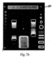
図7aは、放射線治療装置によるプログラム制御下で生成され、基準位置のファントムに向けられる一連のビームを表している。図7bは、2D検出器から取得される対応画像を表している。これらの画像から、上で検討したような、ビームエネルギー及び調整等の異なるパラメータが得られてもよい。また、スポットサイズ及び位置は公知の方法で検証されてもよい。 FIG. 7a shows a series of beams generated under program control by a radiation therapy device and directed at a phantom in a reference position. FIG. 7b shows the corresponding image obtained from the 2D detector. From these images, different parameters, such as beam energy and adjustment, as discussed above, may be obtained. Further, the spot size and the position may be verified by a known method.
発明のファントム10内のフレーム構造体30の存在は、以下の多くの利点を有する:ファントムは容易に操作することができ、フレームはファントムの様々な構成部品の位置に対して、信頼性があり、正確な基準であり、マーカ200はレーザ光による正確な位置検証を可能にする。加えて、縁部40は、構成部品をフレームに取り付けるために用いられてもよく:2D検出器は、図8に示すように、プラスチック製クリップ220を介してフレームに保持されるフィルム検出器であってもよい。2D検出器は、また、カメラを備えるシンチレータベースの検出器であってもよく、クリップ220を介してフレームに取り付けられてもよい。
The presence of the
発明のファントム及び方法を用いることによって、位置決めシステム、X線撮像システム、ビーム指向システム等の前記装置の構成部品、線量を含む粒子線治療装置の機能、線量の日々の検証を、信頼できる方法で行うことが可能である。プログラム制御下で行う場合、方法は、特に効果的及び迅速であり、10分未満で完全な品質保証を行うことが可能である。発明の方法により、治療医は、ファントムに対する変更を行うために治療室に入室すること、及び測定を行うために治療室を退室すること等の多くの時間を浪費する操作を不要にしている。 By using the phantom and the method of the invention, the components of the device, such as the positioning system, the X-ray imaging system, the beam directing system, the function of the particle beam therapy device including the dose, and the daily verification of the dose can be reliably determined. It is possible to do. When performed under program control, the method is particularly effective and fast, with a complete quality assurance in less than 10 minutes. The method of the present invention eliminates the need for the treating physician to enter the treatment room to make changes to the phantom and to exit the treatment room to make measurements, and the like.
本発明を、特定の実施形態に着目して説明してきたが、それは、本発明の例証であり、制限するものとして解釈すべきではない。より一般的には、本発明が、特に示し、及び/又は、上で説明してきたものによって制限されないことは、当該技術に精通する者によって正しく理解されるであろう。 Although the invention has been described with reference to particular embodiments, it is illustrative of the invention and should not be construed as limiting. More generally, it will be appreciated by those skilled in the art that the present invention is not limited by what has been particularly shown and / or described above.
特許請求の範囲における符号は、それらの保護範囲を制限するものではない。動詞「備える」、「含む」、「から成る」、又は、何れかの他の変形、並びにそれらのそれぞれの語形変化の使用は、説明したそれら以外の要素の存在を除外するものではない。要素の前の冠詞「a」、「an」、又は「the」の使用は、複数のかかる要素の存在を除外するものではない。 The reference signs in the claims do not limit their scope of protection. Use of the verbs "comprise," "includes," "consists of," or any other modification thereof, as well as their respective inflections, does not exclude the presence of other elements described. Use of the article "a", "an", or "the" before an element does not exclude the presence of a plurality of such elements.
Claims (20)
a)第1の面(50)及び前記第1の面と平行な第2の面(60)を有し、RX透過材でできている縁部(40)を有するフレーム構造体(30)と、
b)前記第1の面に対して配向され、それと平行な第1のウェッジ面(80)と、前記第1の面に対向して配向され、前記第1の面(50)に対して傾斜される第2のウェッジ(90)面とをそれぞれが有する1つ以上のウェッジ(70)と、
c)前記第1の面に対して配向され、それと平行な第1のブロック面(110)と、前記第2の面(60)に対して配向され、それと平行な第2のブロック面(120)とを有する第1の材料ブロック(100)であって、絶対線量計(130)が前記第1のブロック面(110)に配置される、第1の材料ブロック(100)と、
d)前記第1の面に対して配向され、それと平行な第1のブロック面(150)と、前記第2の面(60)に対して配向され、それと平行な第2のブロック面(160)とを有する第2の材料ブロック(140)と、
e)前記第1(100)及び/又は前記第2のブロック(140)に位置する高密度材料の複数のビード(170)と、
f)前記第2の面に配置される2D検出器(180)と、を備え、
前記1つ以上のウェッジ(70)、第1の材料ブロック、絶対線量計、第2の材料ブロック、高密度材料の複数のビード(170)、及び2D検出器(180)が、前記フレーム構造体(30)に関して既知の固定位置にあるファントム(10)において、
高密度材料の中央ビード(175)は、前記フレーム構造体(30)に関して中央の既知の固定位置に保持され、前記1つ以上のウェッジ(70)、前記第1(100)及び第2の材料ブロック(140)は、前記第1の面(50)から、そして、それと垂直に、前記中央ビード(175)を通って前記ファントム(10)を横断するビームが、前記中央ビード(175)の他に何れかの材料も横断することなく、前記第2の面(60)に到達するように、前記フレーム構造体(30)内に配置される、
ことを特徴とするファントム。 A phantom (10) for quality assurance of a particle beam therapy device usable in an intensity modulated particle beam therapy (IMPT) mode,
a) a frame structure (30) having a first surface (50) and a second surface (60) parallel to said first surface and having an edge (40) made of RX permeable material; ,
b) a first wedge surface (80) oriented with and parallel to said first surface, and oriented opposite to said first surface and inclined with respect to said first surface (50). One or more wedges (70) each having a second wedge (90) surface to be provided;
c) a first block surface (110) oriented parallel to and parallel to the first surface, and a second block surface (120) oriented parallel to and parallel to the second surface (60). A first material block (100) having an absolute dosimeter (130) disposed on said first block surface (110);
d) a first block surface (150) oriented with and parallel to said first surface and a second block surface (160) oriented with and parallel to said second surface (60). A second material block (140) comprising:
e) said first (1 0 0) and / or a plurality of beads of high density material positioned in said second block (140) and (170),
f) a 2D detector (180) disposed on the second surface;
The one or more wedges (70), a first block of material, an absolute dosimeter, a second block of material, a plurality of beads of high density material (170), and a 2D detector (180) are provided on the frame structure. In a phantom (10) in a known fixed position with respect to (30),
A central bead of high density material (175) is held in a central, known fixed position with respect to the frame structure (30), and the one or more wedges (70), the first (100) and the second material The block (140) includes a beam that traverses the phantom (10) through the central bead (175) and from the first surface (50) and perpendicular to the other of the central bead (175). Disposed within the frame structure (30) so as to reach the second surface (60) without traversing any of the materials.
A phantom characterized by that.
a)請求項1〜8の何れか一項に記載のファントム(10)を提供するステップと、
b)前記ファントム(10)を前記患者ポジショナ上に位置決めするステップと、
c)前記患者ポジショナを前記基準位置に位置決めするステップと、
d)前記ファントムの中央の既知の固定位置に向けられるペンシルビームを前記ファントム(10)に照射し、且つ、前記2D検出器(180)上で前記ペンシルビームの画像を取得するステップと、
e)前記画像から、前記中央ビード(175)と前記ペンシルビームとの間の距離を計算するステップと、
を含むことを特徴とする方法。 A method for quality assurance of a particle therapy device usable in an intensity modulated particle therapy (IMPT) configuration, the device comprising a patient positioner having a reference position, and an X-ray source and a 2D X-ray detector, respectively. And two or more x-ray systems comprising:
a) providing a phantom (10) according to any one of claims 1 to 8;
b) positioning the phantom (10) on the patient positioner;
c) positioning the patient positioner at the reference position;
d) illuminating the phantom (10) with a pencil beam directed at a known fixed position in the center of the phantom and acquiring an image of the pencil beam on the 2D detector (180);
e) calculating a distance between the central bead (175) and the pencil beam from the image;
A method comprising:
f)前記患者ポジショナを前記基準位置から既知のオフセットベクトルに位置決めするステップと、
g)前記ファントム(10)の1つ以上のX線画像を前記2D X線検出器上で取得するステップと、
h)前記2D X線検出器上での前記高密度材料ビード(170、175)の前記画像から、前記患者ポジショナを前記基準位置に移動させるための修正ベクトルを計算するステップと、
i)前記オフセットベクトルの、且つ、前記修正ベクトルの合計が閾値未満であることを検証するステップと、
を含むことを特徴とする方法。 10. The method according to claim 9, further comprising, between steps b) and c):
f) positioning the patient positioner at a known offset vector from the reference position;
g) obtaining one or more X-ray images of the phantom (10) on the 2D X-ray detector;
h) calculating a correction vector for moving the patient positioner to the reference position from the image of the dense material bead (170, 175) on the 2D X-ray detector;
a step of verifying that i) of the offset vector, and, the sum of the correction vector is less than the threshold value,
A method comprising:
j)それぞれが同じエネルギーを有する複数のペンシルビームを前記ファントム(10)に対して照射し、且つ、前記2D検出器(180)上で前記ペンシルビームの前記画像を取得するステップと、
k)前記画像から、ビーム範囲、スポットサイズ、スポット位置を計算するステップと、
l)前記絶対放射線検出器(130)から放射線量を取得するステップと、
m)前記ビーム範囲、スポットサイズ、スポット位置、及び放射線量が、期待ビーム範囲、スポットサイズ、スポット位置、及び放射線量からの範囲内にあることを検証するステップと、
を含むことを特徴とする方法。 11. The method according to any one of claims 9 or 10, further comprising after step c):
j) illuminating the phantom (10) with a plurality of pencil beams, each having the same energy, and acquiring the image of the pencil beam on the 2D detector (180);
k) calculating a beam range, a spot size, and a spot position from the image;
l) obtaining a radiation dose from said absolute radiation detector (130);
m) verifying that the beam range, spot size, spot position, and radiation dose are within a range from the expected beam range, spot size, spot position, and radiation dose;
A method comprising:
n)光又はレーザ光の1つ以上のファンを前記視認マーカ(200)に向けるステップと、
o)前記視認マーカ(200)との光又はレーザ光の前記ファンの一致を検証するステップと、
を含むことを特徴とする方法。 The method according to any one of claims 9 to 11, wherein the phantom (10) comprises a visual marker (200) at a known location on one or more of the edges (40), the method further comprising: ,
n) directing one or more fans of light or laser light toward the viewing marker (200);
o) verifying the match of the fan of light or laser light with the visual marker (200);
A method comprising:
Applications Claiming Priority (3)
| Application Number | Priority Date | Filing Date | Title |
|---|---|---|---|
| EP15165139 | 2015-04-24 | ||
| EP15165139.5 | 2015-04-24 | ||
| PCT/EP2016/059009 WO2016170115A1 (en) | 2015-04-24 | 2016-04-22 | Phantom and method for quality assurance of a particle therapy apparatus |
Publications (3)
| Publication Number | Publication Date |
|---|---|
| JP2018513746A JP2018513746A (en) | 2018-05-31 |
| JP2018513746A5 JP2018513746A5 (en) | 2019-07-25 |
| JP6625662B2 true JP6625662B2 (en) | 2019-12-25 |
Family
ID=53180519
Family Applications (1)
| Application Number | Title | Priority Date | Filing Date |
|---|---|---|---|
| JP2017555312A Active JP6625662B2 (en) | 2015-04-24 | 2016-04-22 | Phantom and method for quality assurance of particle beam therapy equipment |
Country Status (5)
| Country | Link |
|---|---|
| US (1) | US10105119B2 (en) |
| EP (1) | EP3285869B1 (en) |
| JP (1) | JP6625662B2 (en) |
| CN (1) | CN107530039B (en) |
| WO (1) | WO2016170115A1 (en) |
Families Citing this family (6)
| Publication number | Priority date | Publication date | Assignee | Title |
|---|---|---|---|---|
| EP3421086B1 (en) * | 2017-06-28 | 2020-01-15 | OptiNav Sp. z o.o. | Determination of geometrical information about a medical treatment arrangement comprising a rotatable treatment radiation source unit |
| CN109745634B (en) * | 2018-12-25 | 2020-09-25 | 江苏海明医疗器械有限公司 | Multi-blade collimator testing device for medical accelerator |
| EP3750597B1 (en) * | 2019-06-13 | 2021-10-06 | Ion Beam Applications S.A. | Phantom and method for the quality assurance of a hadron therapy apparatus |
| GB2603764B (en) * | 2021-02-10 | 2023-05-17 | Elekta ltd | Detection device for determining a position of a phantom |
| CN113031048B (en) * | 2021-03-05 | 2022-11-15 | 中国科学院近代物理研究所 | Device and method for fast quality control verification of ion beam range |
| KR102593247B1 (en) * | 2021-06-21 | 2023-10-24 | 주식회사 쓰리디산업영상 | Geometric calibration method and apparatus of computer tomography |
Family Cites Families (8)
| Publication number | Priority date | Publication date | Assignee | Title |
|---|---|---|---|---|
| GB9111074D0 (en) * | 1991-05-22 | 1991-07-17 | Philips Electronic Associated | A method for verifying a target position |
| EP1747799A1 (en) | 2005-07-27 | 2007-01-31 | Ion Beam Applications S.A. | Dosimetry device for verification of a radiation therapy apparatus |
| US7356120B2 (en) * | 2005-09-23 | 2008-04-08 | Accuray Incorporated | Integrated quality assurance for in image guided radiation treatment delivery system |
| US7714309B2 (en) * | 2007-02-27 | 2010-05-11 | Wisconsin Alumni Research Foundation | Phantom for ion range detection |
| DE102007011154A1 (en) * | 2007-03-07 | 2008-09-11 | Siemens Ag | Phantom and method for quality control of a medical device and particle therapy system |
| DE202011104321U1 (en) * | 2011-08-12 | 2011-11-16 | Universitätsklinikum Frankfurt am Main | Measuring phantoms for checking the positioning accuracy of patient positioning devices in percutaneous radiotherapy on CTs, simulators and linear accelerators as well as the imaging properties of their imaging systems and the correct data transmission and data handling between the different systems (NK-100) |
| EP2841160B1 (en) * | 2012-04-25 | 2018-04-11 | Ion Beam Applications S.A. | Apparatus and method for hadron beam verification |
| US9643029B2 (en) | 2013-09-26 | 2017-05-09 | Varian Medical Systems International Ag | Dosimetric end-to-end verification devices, systems, and methods |
-
2016
- 2016-04-22 EP EP16718336.7A patent/EP3285869B1/en active Active
- 2016-04-22 CN CN201680022629.3A patent/CN107530039B/en active Active
- 2016-04-22 JP JP2017555312A patent/JP6625662B2/en active Active
- 2016-04-22 US US15/567,879 patent/US10105119B2/en active Active
- 2016-04-22 WO PCT/EP2016/059009 patent/WO2016170115A1/en active Application Filing
Also Published As
| Publication number | Publication date |
|---|---|
| CN107530039B (en) | 2020-05-05 |
| US20180098745A1 (en) | 2018-04-12 |
| EP3285869B1 (en) | 2019-06-12 |
| WO2016170115A1 (en) | 2016-10-27 |
| EP3285869A1 (en) | 2018-02-28 |
| US10105119B2 (en) | 2018-10-23 |
| JP2018513746A (en) | 2018-05-31 |
| CN107530039A (en) | 2018-01-02 |
Similar Documents
| Publication | Publication Date | Title |
|---|---|---|
| JP6625662B2 (en) | Phantom and method for quality assurance of particle beam therapy equipment | |
| US11691031B2 (en) | Systems, methods, and devices for radiation beam asymmetry measurements using electronic portal imaging devices | |
| Arjomandy et al. | AAPM task group 224: comprehensive proton therapy machine quality assurance | |
| US20210138272A1 (en) | Systems, methods, and devices for radiation beam alignment and radiation beam measurements using electronic portal imaging devices | |
| US7679049B2 (en) | Calibrating a positron emission tomography scanner | |
| US7786433B2 (en) | Phantom and method for quality monitoring of a medical system | |
| Boggula et al. | Evaluation of a 2D detector array for patient-specific VMAT QA with different setups | |
| JP6578574B2 (en) | Radiation therapy device calibration phantom | |
| JP6073463B2 (en) | Apparatus and method for hadron beam verification | |
| Miao et al. | Cherenkov imaging for linac beam shape analysis as a remote electronic quality assessment verification tool | |
| Vatnitsky et al. | Radiochromic film dosimetry for verification of dose distributions delivered with proton-beam radiosurgery | |
| Huang et al. | Experimental determination of electron source parameters for accurate Monte Carlo calculation of large field electron therapy | |
| US8907308B2 (en) | Method and apparatus for verifying an irradiation field | |
| JP7404160B2 (en) | Phantom and method for quality assurance of hadron therapy equipment | |
| Mastella et al. | Validation of a pretreatment delivery quality assurance method for the CyberKnife Synchrony system | |
| Groppo et al. | Determination of the penumbra width of Elekta SRS cone collimator for 6 MV FF and 6 MV FFF energies using gradient-based edge detection | |
| Ma et al. | Application of a video-optical beam imaging system for quality assurance of medical accelerators | |
| Yoon et al. | Acceptance testing and commissioning of robotic intensity-modulated radiation therapy M6 system equipped with InCiseTM2 multileaf collimator | |
| JP6914053B2 (en) | QA method and system for radiotherapy equipment or diagnostic equipment | |
| Chełmiński et al. | Measurement of the sensitometric curves of Kodak EDR2 and X-Omat V films using Enhanced Dynamic Wedges and Dynamic Multileaf Collimators | |
| Azcona-Armendariz et al. | Commissioning of a synchrotron-based proton beam therapy system for use with a Monte Carlo treatment planning system | |
| Rahmat et al. | Position accuracy evaluation of multileaf collimator (MLC) static in linear accelerator | |
| Sumida et al. | Megavoltage beam commissioning | |
| Han et al. | X-ray collimator design using monte carlo simulations | |
| Vahc et al. | Beam intensity scanner system for three dimensional dose verification of IMRT |
Legal Events
| Date | Code | Title | Description |
|---|---|---|---|
| A621 | Written request for application examination |
Free format text: JAPANESE INTERMEDIATE CODE: A621 Effective date: 20190219 |
|
| A521 | Request for written amendment filed |
Free format text: JAPANESE INTERMEDIATE CODE: A523 Effective date: 20190618 |
|
| A871 | Explanation of circumstances concerning accelerated examination |
Free format text: JAPANESE INTERMEDIATE CODE: A871 Effective date: 20190618 |
|
| A975 | Report on accelerated examination |
Free format text: JAPANESE INTERMEDIATE CODE: A971005 Effective date: 20190701 |
|
| A131 | Notification of reasons for refusal |
Free format text: JAPANESE INTERMEDIATE CODE: A131 Effective date: 20190716 |
|
| A521 | Request for written amendment filed |
Free format text: JAPANESE INTERMEDIATE CODE: A523 Effective date: 20191004 |
|
| TRDD | Decision of grant or rejection written | ||
| A01 | Written decision to grant a patent or to grant a registration (utility model) |
Free format text: JAPANESE INTERMEDIATE CODE: A01 Effective date: 20191119 |
|
| A61 | First payment of annual fees (during grant procedure) |
Free format text: JAPANESE INTERMEDIATE CODE: A61 Effective date: 20191127 |
|
| R150 | Certificate of patent or registration of utility model |
Ref document number: 6625662 Country of ref document: JP Free format text: JAPANESE INTERMEDIATE CODE: R150 |
|
| R250 | Receipt of annual fees |
Free format text: JAPANESE INTERMEDIATE CODE: R250 |
|
| R250 | Receipt of annual fees |
Free format text: JAPANESE INTERMEDIATE CODE: R250 |