JP6625451B2 - Ten wheel - Google Patents
Ten wheel Download PDFInfo
- Publication number
- JP6625451B2 JP6625451B2 JP2016044311A JP2016044311A JP6625451B2 JP 6625451 B2 JP6625451 B2 JP 6625451B2 JP 2016044311 A JP2016044311 A JP 2016044311A JP 2016044311 A JP2016044311 A JP 2016044311A JP 6625451 B2 JP6625451 B2 JP 6625451B2
- Authority
- JP
- Japan
- Prior art keywords
- rim
- wheel
- arm
- metal
- wheel according
- Prior art date
- Legal status (The legal status is an assumption and is not a legal conclusion. Google has not performed a legal analysis and makes no representation as to the accuracy of the status listed.)
- Active
Links
- 229910052751 metal Inorganic materials 0.000 claims description 42
- 239000002184 metal Substances 0.000 claims description 42
- 239000000463 material Substances 0.000 claims description 40
- 229920003002 synthetic resin Polymers 0.000 claims description 13
- 239000000057 synthetic resin Substances 0.000 claims description 13
- 230000005484 gravity Effects 0.000 claims description 4
- 230000002093 peripheral effect Effects 0.000 claims description 4
- PXHVJJICTQNCMI-UHFFFAOYSA-N Nickel Chemical compound [Ni] PXHVJJICTQNCMI-UHFFFAOYSA-N 0.000 description 20
- 238000007747 plating Methods 0.000 description 20
- DOSMHBDKKKMIEF-UHFFFAOYSA-N 2-[3-(diethylamino)-6-diethylazaniumylidenexanthen-9-yl]-5-[3-[3-[4-(1-methylindol-3-yl)-2,5-dioxopyrrol-3-yl]indol-1-yl]propylsulfamoyl]benzenesulfonate Chemical compound C1=CC(=[N+](CC)CC)C=C2OC3=CC(N(CC)CC)=CC=C3C(C=3C(=CC(=CC=3)S(=O)(=O)NCCCN3C4=CC=CC=C4C(C=4C(NC(=O)C=4C=4C5=CC=CC=C5N(C)C=4)=O)=C3)S([O-])(=O)=O)=C21 DOSMHBDKKKMIEF-UHFFFAOYSA-N 0.000 description 18
- 229910052759 nickel Inorganic materials 0.000 description 10
- 229920005989 resin Polymers 0.000 description 9
- 239000011347 resin Substances 0.000 description 9
- 238000000034 method Methods 0.000 description 8
- RYGMFSIKBFXOCR-UHFFFAOYSA-N Copper Chemical compound [Cu] RYGMFSIKBFXOCR-UHFFFAOYSA-N 0.000 description 7
- 229910052802 copper Inorganic materials 0.000 description 7
- 239000010949 copper Substances 0.000 description 7
- 238000004519 manufacturing process Methods 0.000 description 6
- KDLHZDBZIXYQEI-UHFFFAOYSA-N Palladium Chemical compound [Pd] KDLHZDBZIXYQEI-UHFFFAOYSA-N 0.000 description 4
- 230000004048 modification Effects 0.000 description 4
- 238000012986 modification Methods 0.000 description 4
- VYZAMTAEIAYCRO-UHFFFAOYSA-N Chromium Chemical compound [Cr] VYZAMTAEIAYCRO-UHFFFAOYSA-N 0.000 description 3
- 229910052804 chromium Inorganic materials 0.000 description 3
- 239000011651 chromium Substances 0.000 description 3
- 239000007769 metal material Substances 0.000 description 3
- 229920003023 plastic Polymers 0.000 description 3
- ATJFFYVFTNAWJD-UHFFFAOYSA-N Tin Chemical compound [Sn] ATJFFYVFTNAWJD-UHFFFAOYSA-N 0.000 description 2
- 239000003054 catalyst Substances 0.000 description 2
- PCHJSUWPFVWCPO-UHFFFAOYSA-N gold Chemical compound [Au] PCHJSUWPFVWCPO-UHFFFAOYSA-N 0.000 description 2
- 229910052737 gold Inorganic materials 0.000 description 2
- 239000010931 gold Substances 0.000 description 2
- 229910052763 palladium Inorganic materials 0.000 description 2
- 239000004575 stone Substances 0.000 description 2
- 229910052718 tin Inorganic materials 0.000 description 2
- 239000011135 tin Substances 0.000 description 2
- 229920000122 acrylonitrile butadiene styrene Polymers 0.000 description 1
- 239000000443 aerosol Substances 0.000 description 1
- 239000000956 alloy Substances 0.000 description 1
- 229910045601 alloy Inorganic materials 0.000 description 1
- 238000006243 chemical reaction Methods 0.000 description 1
- 239000012141 concentrate Substances 0.000 description 1
- 238000005336 cracking Methods 0.000 description 1
- 238000005520 cutting process Methods 0.000 description 1
- 238000000151 deposition Methods 0.000 description 1
- 238000006073 displacement reaction Methods 0.000 description 1
- 230000000694 effects Effects 0.000 description 1
- 238000009713 electroplating Methods 0.000 description 1
- 238000005530 etching Methods 0.000 description 1
- 239000010419 fine particle Substances 0.000 description 1
- 238000009499 grossing Methods 0.000 description 1
- 238000000465 moulding Methods 0.000 description 1
- 230000001681 protective effect Effects 0.000 description 1
- 238000005507 spraying Methods 0.000 description 1
Images


Description
本発明は、機械式時計に用いられるテン輪に関する。さらに詳しくは、大きな衝撃が加わった場合における変形を防止する機能を備えたテン輪の構造に関する。 The present invention relates to a balance wheel used for a mechanical timepiece. More specifically, the present invention relates to a ten wheel structure having a function of preventing deformation when a large impact is applied.
機械式時計の調速装置として、ヒゲゼンマイと組み合わせて往復回転振動を行うテン輪が用いられる。このテン輪の通常の構造を以下に述べる。リムと呼ばれるリング状の部材がその主体であり、リムはその中心軸に一致し、その回転往復運動の支軸となるテン真と、リムと一体形成されリムの直径に沿って配置されたアームと呼ばれる平板状で細長い部材によって固着結合されている。アームはテン輪の質量をリムに極力集中させ軽くするため、リムの厚さよりも薄く成型される。 As a speed control device of a mechanical timepiece, a ten wheel that performs reciprocating rotational vibration in combination with a balance spring is used. The normal structure of this wheel is described below. A ring-shaped member called a rim is a main component of the rim. The rim coincides with the center axis of the rim, and serves as a support shaft for the reciprocating rotation of the rim and an arm integrally formed with the rim and arranged along the diameter of the rim. And is fixedly connected by a flat and elongated member called a so-called flat member. The arm is formed thinner than the rim thickness in order to concentrate the mass of the ten wheel on the rim as much as possible.
このような通常構造においては、強い衝撃が特にテン真の軸方向(リムの円環の面と垂直な方向でもある)に加わった場合にテン輪が変形し易い。すなわち、衝撃を受けた結果、平板であったアームが山形に塑性変形することがあるという欠点がある。このような変形が起こるとテン輪は変位して時計ムーブメント内で近接するほかの部品と干渉(接触)して自由な振動運動ができなくなり、時計が停止してしまう事態も生じ得る。 In such a normal structure, the ten wheel is easily deformed particularly when a strong impact is applied in the axial direction of the true tenn (also in the direction perpendicular to the surface of the ring of the rim). That is, as a result of the impact, there is a disadvantage that the flat arm may be plastically deformed into a mountain shape. When such a deformation occurs, the ten wheel is displaced and interferes (contacts) with other components in the timepiece movement close to each other, so that free vibration movement is not possible, and the timepiece may stop.
このようなテン真の軸方向の衝撃を緩和できるテン輪構造として特許文献1が知られている。特許文献1では、テン輪は金属製のリムにプラスチック製のアームを取り付けた構成となっており、このプラスチック製アームの弾性によって軸方向の衝撃が低減されている。
しかしながら、特許文献1に記載のような構造は、リムとアームをそれぞれ形成し嵌め合せることでテン輪を形成している。そのため、衝撃を受けた際にリムが外れテン輪が分解してしまう問題がある。
However, the structure as described in
また、特許文献1に記載のものに限らず、複数の部材から構成されるテン輪は、各部品の組み立て精度のばらつきによって、テン輪回転中心をテン真の回転軸と一致させるのが困難である。
In addition, not only the ten wheel described in
本発明の主要な目的は、衝撃を受けた際に分解することなく、軸方向の衝撃によって変形し難いテン輪を構成することである。また、副次的な目的は、組み立て誤差による偏心を防ぐ構成とすることである。 A main object of the present invention is to configure a ten wheel that is not easily disassembled by an impact in an axial direction without being disassembled when subjected to an impact. A secondary purpose is to prevent the eccentricity due to an assembly error.
本発明のテン輪は、上記目的を達成するため、以下の構成を採用する。 The ten wheel of the present invention employs the following configuration to achieve the above object.
テン真が挿入される接続部品と、接続部品と接続されるアームと、アームと接続されるリムと、を有するテン輪であって、アーム及びリムは、それぞれ第1の材料によって形成され、前記リムは、前記第1の材料よりも比重の大きい第2の材料によって覆われており、前記第1の材料と前記第2の材料との間に中間層を有し、さらに、前記リムの表面には複数の微孔が形成され、前記微孔及び前記リムの表面上に中間層が形成されることを特徴とする。
また、第2の材料は、金属であってもよく、第1の材料は、合成樹脂であってもよい。
A ten wheel having a connecting part into which a balance is inserted, an arm connected to the connecting part, and a rim connected to the arm, wherein the arm and the rim are each formed of a first material, rim before SL is covered by a large second material specific gravity than the first material, an intermediate layer between the first material and the second material, further, the rim A plurality of fine holes are formed on the surface, and an intermediate layer is formed on the surface of the fine holes and the rim .
Further, the second material may be a metal, and the first material may be a synthetic resin.
このように構成することによって、衝撃を受けた際に分解することなく、軸方向の衝撃によって変形し難いテン輪を得ることができる。 With this configuration, it is possible to obtain a ten wheel that is not easily deformed by an axial impact without being disassembled when receiving an impact.
また、第2の材料は、第1の材料よりも弾性率が高くてもよい。
また、接続部品は、第1の材料と異なる材料で覆われていてもよい。
さらに、接続部品、アーム及びリムは、一体に形成されていてもよい。
Further , the second material may have a higher elastic modulus than the first material .
Further, the connection component may be covered with a material different from the first material.
Furthermore, the connecting part, the arm and the rim may be formed integrally.
このように構成することによって、テン輪の耐衝撃性を高めた具体的な構造を提供することができる。 With this configuration, it is possible to provide a specific structure in which the impact resistance of the ten wheel is enhanced.
また、第2の材料は、前記リムの外周に沿って複数に分割されて配置されていてもよい。
また、第1の材料と前記第2の材料との間に、中間層を有していてもよい。
さらに、中間層は、第1の材料及び第2の材料のいずれとも異なっていてもよい。
Further , the second material may be divided into a plurality of pieces along the outer periphery of the rim .
Further, an intermediate layer may be provided between the first material and the second material.
Further, the intermediate layer may be different from any of the first material and the second material.
このように構成することによって、めっき時に樹脂部材への導電性を付与することができる。 With this configuration, it is possible to impart conductivity to the resin member during plating.
合成樹脂で成型したテン輪の一部を金属で覆うことで、衝撃を受けた際に分解することなく、振動運動に必要な慣性モーメントも備えたテン輪を構成することができる。 By covering a part of the ten wheel molded with a synthetic resin with metal, a ten wheel having a moment of inertia necessary for a vibrating motion can be formed without being disassembled upon receiving an impact.
本発明は、テン真が挿入される接続部品と、接続部品と接続されるアームと、アームと接続されるリムと、を有するテン輪であって、接続部品、アーム及びリムは、それぞれ合成樹脂によって形成され、接続部品とリムのうち、少なくとも一方は、金属によって合成樹脂が覆われている金属部を有することを特徴とする。 The present invention is a ten wheel having a connection part into which a balance is inserted, an arm connected to the connection part, and a rim connected to the arm, wherein the connection part, the arm and the rim are each made of synthetic resin. And at least one of the connection component and the rim has a metal portion covered with a synthetic resin by a metal.
以下、本発明の実施形態例について、図面を用いて詳細に説明する。 Hereinafter, embodiments of the present invention will be described in detail with reference to the drawings.
<第1実施形態の要部構造:図1、図2>
本発明のテン輪の第1実施形態について、図1及び図2を用いて説明する。図1は完成したテン輪の斜視図である。図2は、リム1の構造の詳細を示すための、図1のA−A断面図である。
<Main Structure of First Embodiment: FIGS. 1 and 2>
A first embodiment of a balance wheel according to the present invention will be described with reference to FIGS. FIG. 1 is a perspective view of the completed ten wheel. FIG. 2 is a sectional view taken along line AA of FIG. 1 for showing details of the structure of the
図1に示すように、テン輪は、リム1とアーム2と接続部品3で構成され、テン真5が接続部品3に挿入され嵌合している。リム1はテン輪に必要な慣性モーメントを与えるリング状部材であり、金属である金属部4がリム1の一部を覆うように形成されている。また、リム1の内周において平板状のアーム2の一端と接続されている。平板状のアーム2の他端は接続部品3と接続されており、リム1はアーム2を介して接続部品3に支えられている構造となっている。接続部品3は略円筒状の形状をしており、中心にテン真5と嵌合する開口部を有している。テン真5はテン輪の回転軸であり、接続部品3に嵌合する円
筒状の形状をしている。このテン真5の上端部と下端部は、通常回転摩擦を少なくするため細く加工されてホゾ部となっている。ホゾ部はラジアル軸受である穴石に挿入され先端部はスラスト軸受である受石で受けられる。
As shown in FIG. 1, the ten wheel includes a
図2に示すように、アーム2はリム1と接続部品3とは、それぞれ接続された形状になっている。このアーム2とリム1と接続部品3はABS樹脂などの合成樹脂材料を用いることができ、金型加工などの公知技術によって一体に形成される。このように、アーム2とリム1と接続部品3とを一体加工することにより、製造ばらつきを抑えることができる。
As shown in FIG. 2, the
リム1の上面、下面及び外周側の側面には金属部4が形成されている。金属部4は銅が用いられるが、これに限定されず、ニッケル、錫、クロム、金、又はこれらの合金などの材料を用いることができる。形成方法としてはめっき技術を使用することができる。
The
このような構造のテン輪が軸方向の衝撃を受けた際、アーム2が変形する度合いはアーム2に使用する材料の特性によって決まる。合成樹脂材料は金属材料に比べ弾性率が低く、同一の形状に対して同じ荷重を受けた際の変形量が金属材料に比べて大きい。そのため、金属材料を用いたアームが塑性変形する大きさの荷重と同じ荷重を合成樹脂材料のアームにかけたとしても、塑性変形する前に他の時計部品との接触によって変形が抑えられる。
The degree of deformation of the
これにより、衝撃を受けた際のアーム部の変形は合成樹脂の弾性範囲での変形にとどまり、衝撃を受けても元の形状に復帰することができる。 As a result, the deformation of the arm portion upon receiving an impact is limited to the deformation within the elastic range of the synthetic resin, and can return to the original shape even when receiving the impact.
また、上述したとおり、リム1とアーム2と接続部品3とを一体成型した構造とすることで、個別に作製したリム部品やアーム部品を組み立てる必要がなく、組み立て誤差によるテン輪の偏心を防ぐことができる。
Further, as described above, since the
さらに、上述したとおり、テン輪の内周部を占めるアーム及び接続部品は低比重の合成樹脂で構成され、高比重の金属部材は外周部であるリム部にのみ配置されることになる。これによって、テン輪の回転半径が大きくなり、外乱の影響を受けにくい往復回転振動を得ることができる。 Further, as described above, the arms and connecting parts occupying the inner peripheral portion of the ten wheel are made of low specific gravity synthetic resin, and the high specific gravity metal member is disposed only on the rim portion which is the outer peripheral portion. As a result, the turning radius of the balance wheel is increased, and reciprocating rotational vibration that is less affected by disturbance can be obtained.
<金属部4の形成方法の説明:図3、図4>
次に、図3及び図4を用いて本実施例のテン輪の製造方法について説明する。図3は図2の領域Bの拡大図であり、図4は図3における金属部4の製造工程を示す。
<Description of Method for Forming Metal Part 4: FIGS. 3 and 4>
Next, a method of manufacturing the ten wheel according to the present embodiment will be described with reference to FIGS. FIG. 3 is an enlarged view of a region B in FIG. 2, and FIG. 4 shows a manufacturing process of the
本実施形態においては、合成樹脂への金属部の配置は樹脂めっき技術を用いて行う。ここで、樹脂めっきを行う部材は一体成型されたリム1とアーム2と接続部品3であるため、接続部品3の開口部にテン真5を挿入して嵌合させる前に行うのが好ましい。
In the present embodiment, the metal part is disposed on the synthetic resin by using a resin plating technique. Here, since the members to be resin-plated are the
図3に示す通り、リム1の表面には複数の微孔11が形成されており、微孔11及びリム1の表面上に中間層6であるニッケル層が形成されている。また、中間層6上に金属部4である銅が形成されている。この構成の製造方法について図4を用いて詳細に説明を行う。
As shown in FIG. 3, a plurality of
まず、樹脂表面に導電性を付与するための前工程として、無電解ニッケルめっき処理を行う。無電解ニッケルめっき処理については、図4(a)と図4(b)を用いて説明を行う。図4(a)に示すように、無電解ニッケルめっき処理を行う工程として、はじめにリム1の合成樹脂表面に親水性を付与するために表面をエッチングし微孔11を設ける。エ
ッチング工程において、微孔11を要しないアーム2や接続部3の領域にはマスク等を形成しておくとよい。
First, an electroless nickel plating process is performed as a pre-process for imparting conductivity to the resin surface. The electroless nickel plating will be described with reference to FIGS. 4A and 4B. As shown in FIG. 4A, as a step of performing the electroless nickel plating treatment, first, the surface of the synthetic resin of the
次に、この微孔11にパラジウム触媒を吸着させる。これは、パラジウム触媒を核として化学反応が起こり、樹脂表面にニッケルめっきを行うためである。これにより、図4(b)に示すように、微孔11及びリム1の合成樹脂表面上にニッケルめっきによって中間層6が形成される。この中間層6は、微孔11によるアンカー効果によって樹脂表面に強固に密着する。
Next, a palladium catalyst is adsorbed on the
次に、図4(c)に示すように、中間層6上に電気めっきを行い金属部4である銅をめっきする。金属部4の厚さは、テン輪が定められた周期の往復振動運動を行うための慣性モーメントを得るために必要な重量を確保できればよく、銅であれば、数十〜数百ミクロンの厚さが好ましい。
Next, as shown in FIG. 4C, electroplating is performed on the
また、銅4は厚くすることでめっき膜の割れを防ぐことができ、また、平滑化作用も強く無電解ニッケルめっき処理時に設けた微孔を平滑化でき美観に優れる。
Further, by making the
めっき材料は銅に限らず、ニッケルやクロム、錫や金などを用いてもよい。また、めっきした銅の上に更に保護膜を形成したり、より大きな慣性モーメントを得るために、銅の上にさらにニッケルやクロムなどをめっきしたりしてもよい。 The plating material is not limited to copper, but may be nickel, chromium, tin, gold, or the like. Further, a protective film may be further formed on the plated copper, or nickel or chromium may be further plated on the copper in order to obtain a larger moment of inertia.
このようなテン輪の製造方法としては、上記のめっきに限らず、金型を用いて樹脂と金属を一体成型するインサート法や、金属微粒子を樹脂表面に吹き付けるエアロゾルデポジション法などを用いて行ってもよい。 The manufacturing method of such a ten wheel is not limited to the above-described plating, and is performed using an insert method of integrally molding a resin and a metal using a mold, an aerosol deposition method of spraying metal fine particles onto the resin surface, and the like. You may.
<実施形態1の変形例の説明:図5>
次に、上述した実施形態1の金属部の変形例について図5を用いて説明を行う。本変形例と実施形態1との差異は金属部41の構造であり、それ以外の構成については、実施形態1と同様である。図5は、実施形態1の変形例の平面図である。図5に示すように、リム部に設ける金属部41を、テン真5を軸として回転対称になるように分割して設けている。
<Description of Modification of First Embodiment: FIG. 5>
Next, a modification of the metal part of the first embodiment will be described with reference to FIG. The difference between the present modified example and the first embodiment is the structure of the
テン輪の慣性モーメントはリム部に設ける金属のめっき量で定まる。その際、めっき厚さを調整することで慣性モーメントの調整を行うこともできるが、図5のように金属部41を分割して配置することでめっき量を調整すれば、めっきによって形成された金属膜によって樹脂部材に生じる応力を低下させることができ、テン輪の変形を防ぐことができる。
The moment of inertia of the ten wheel is determined by the amount of metal plating provided on the rim. At this time, the moment of inertia can be adjusted by adjusting the plating thickness, but if the amount of plating is adjusted by dividing and arranging the
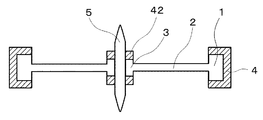
<第2実施形態の要部構造:図6、図7>
次に本発明のテン輪の第2実施形態について、図6及び図7を用いて説明する。第2実施形態の第1実施形態との差異は、接続部品3の表面にも金属部を設けたことである。図6は実施形態2のテン輪の斜視図であり、図7は図6のC−C断面図である。
<Main Structure of Second Embodiment: FIGS. 6 and 7>
Next, a second embodiment of the balance wheel of the present invention will be described with reference to FIGS. The difference of the second embodiment from the first embodiment is that a metal part is also provided on the surface of the
図6及び図7に示すように、接続部品3の上面及び下面にもリム1と同様に金属部42が形成されている。接続部品3にも金属部42を設けることで、テン輪の接続部3とテン真5との勘合をより強固に行うことができる。また、勘合時の樹脂変形によるテン輪の変形やテン輪回転軸のずれを防ぐこともできる。
As shown in FIGS. 6 and 7, the
金属部42は金属部4と同様にめっきなどにより形成することができる。金属部42と金属部4とを同一の材料とする場合は、同じめっき工程で金属部4と金属部42の両方を
同時に形成することができる。また、テン真5との嵌合をより強固にするために金属部4とは別の材料を用いて金属部42を形成する場合は、それぞれ別の工程で行うか、同じめっき工程を行った後に、金属部42の領域のみ追加でめっき工程を行っても良い。
The
また、第2実施形態ではリム1と接続部品3との両方に金属部を設けた構成としたが、接続部品3の表面にのみ金属部を設けた構成としてもよい。この場合も、テン輪の耐衝撃性を向上することができ、テン真5との嵌合強度を高めることができる。
In the second embodiment, the metal part is provided on both the
本発明は、耐衝撃性が増し、また組み立て誤差による偏心を防ぐことができるテン輪の構成を提供できるので、産業上の利用可能性は大きい。 INDUSTRIAL APPLICABILITY The present invention can provide a configuration of a ten wheel capable of increasing impact resistance and preventing eccentricity due to an assembly error, and therefore has great industrial applicability.
1 リム
11 微孔
2 アーム
3 接続部品
4、41、42 金属部
5 テン真
6 中間層
DESCRIPTION OF
Claims (9)
前記アーム及び前記リムは、それぞれ第1の材料によって形成され、
前記リムは、前記第1の材料よりも比重の大きい第2の材料によって覆われており、
前記第1の材料と前記第2の材料との間に中間層を有し、
さらに、
前記リムの表面には複数の微孔が形成され、前記微孔及び前記リムの表面上に中間層が形成される
ことを特徴とするテン輪。 A ten wheel having a connecting part into which the ten stem is inserted, an arm connected to the connecting part, and a rim connected to the arm,
The arm and the rim are each formed of a first material;
It said rim is covered by a large second material specific gravity than before Symbol first material,
An intermediate layer between the first material and the second material;
further,
A ten wheel comprising: a plurality of fine holes formed on a surface of the rim; and an intermediate layer formed on the surfaces of the fine holes and the rim .
ことを特徴とする請求項1に記載のテン輪。 The ten wheel according to claim 1 , wherein the upper surface, the lower surface, and the side surface on the outer peripheral side of the rim are covered with the second material .
ことを特徴とする請求項1又は2に記載のテン輪。 It said second material balance wheel according to claim 1 or 2, characterized in that a high modulus of elasticity than the first material.
ことを特徴とする請求項1から3のいずれか1つに記載のテン輪。 The ten wheel according to any one of claims 1 to 3, wherein the second material is a metal.
ことを特徴とする請求項1から4のいずれか1項に記載のテン輪。 The ten wheel according to any one of claims 1 to 4 , wherein the first material is a synthetic resin.
ことを特徴とする請求項1から5のいずれか1項に記載のテン輪。 The ten wheel according to any one of claims 1 to 5 , wherein the connection component is covered with a material different from the first material.
ことを特徴とする請求項1から6のいずれか1項に記載のテン輪。 The ten wheel according to any one of claims 1 to 6 , wherein the connection component, the arm, and the rim are formed integrally.
ことを特徴とする請求項1から7のいずれか1項に記載のテン輪。 The ten wheel according to any one of claims 1 to 7 , wherein the second material is divided into a plurality of pieces along an outer periphery of the rim.
ことを特徴とする請求項1から8のいずれか1項に記載のテン輪。
The ten wheel according to any one of claims 1 to 8 , wherein the intermediate layer is different from any of the first material and the second material.
Priority Applications (1)
| Application Number | Priority Date | Filing Date | Title |
|---|---|---|---|
| JP2016044311A JP6625451B2 (en) | 2016-03-08 | 2016-03-08 | Ten wheel |
Applications Claiming Priority (1)
| Application Number | Priority Date | Filing Date | Title |
|---|---|---|---|
| JP2016044311A JP6625451B2 (en) | 2016-03-08 | 2016-03-08 | Ten wheel |
Publications (3)
| Publication Number | Publication Date |
|---|---|
| JP2017161287A JP2017161287A (en) | 2017-09-14 |
| JP2017161287A5 JP2017161287A5 (en) | 2018-12-13 |
| JP6625451B2 true JP6625451B2 (en) | 2019-12-25 |
Family
ID=59857876
Family Applications (1)
| Application Number | Title | Priority Date | Filing Date |
|---|---|---|---|
| JP2016044311A Active JP6625451B2 (en) | 2016-03-08 | 2016-03-08 | Ten wheel |
Country Status (1)
| Country | Link |
|---|---|
| JP (1) | JP6625451B2 (en) |
Families Citing this family (2)
| Publication number | Priority date | Publication date | Assignee | Title |
|---|---|---|---|---|
| CN110998957B (en) | 2017-08-24 | 2023-03-24 | 三井化学株式会社 | Nonaqueous electrolyte for battery and lithium secondary battery |
| EP3968097A1 (en) * | 2020-09-09 | 2022-03-16 | Nivarox-FAR S.A. | Clock assembly and method for manufacturing same |
Family Cites Families (5)
| Publication number | Priority date | Publication date | Assignee | Title |
|---|---|---|---|---|
| JPS52122755U (en) * | 1976-03-15 | 1977-09-19 | ||
| CH714952B1 (en) * | 2007-05-08 | 2019-10-31 | Patek Philippe Sa Geneve | Watchmaking component, its method of manufacture and application of this method. |
| EP2104005A1 (en) * | 2008-03-20 | 2009-09-23 | Nivarox-FAR S.A. | Composite balance and method of manufacturing thereof |
| JP6133730B2 (en) * | 2013-09-02 | 2017-05-24 | シチズン時計株式会社 | Balance wheel |
| JP6249480B2 (en) * | 2014-01-22 | 2017-12-20 | セイコーインスツル株式会社 | Timepiece part, movement, timepiece, and method for manufacturing timepiece part |
-
2016
- 2016-03-08 JP JP2016044311A patent/JP6625451B2/en active Active
Also Published As
| Publication number | Publication date |
|---|---|
| JP2017161287A (en) | 2017-09-14 |
Similar Documents
| Publication | Publication Date | Title |
|---|---|---|
| JP5243324B2 (en) | Monolithic hairspring and manufacturing method thereof | |
| JP5134137B2 (en) | Integrated adjustment member and manufacturing method thereof | |
| JP5603458B2 (en) | Compound balance wheel | |
| JP6625451B2 (en) | Ten wheel | |
| JP5280903B2 (en) | Monolithic double balance spring and manufacturing method thereof | |
| US9342053B2 (en) | Method for making a timepiece component | |
| TWI463281B (en) | One-piece hairspring and method of manufacturing the same | |
| JP2018200303A (en) | Guide bearing for timepiece balance pivot | |
| JP2018159711A (en) | Spiral spring | |
| JP5749696B2 (en) | Metal ankle with polymer stag | |
| JP7411040B2 (en) | Bearings of watch movements, especially shock absorbers, and rotary wheel sets | |
| CN104868674B (en) | Rotor and motor | |
| CN105247420A (en) | Bayonet shock absorber | |
| JP6147437B2 (en) | Shock resistant system for watches with two materials | |
| US3935937A (en) | Plastic and metal article of manufacture | |
| JP2014190816A (en) | Spring device for timepiece | |
| US11853007B2 (en) | Horological component intended to receive a member driven in it | |
| JP6853077B2 (en) | Watch parts, movements and watches | |
| JP6639943B2 (en) | Balance wheel and mechanical watch | |
| JP2018163078A (en) | Balance wheel | |
| EP2977834B1 (en) | Shock absorber bearing for timepiece | |
| JP6585968B2 (en) | Spring and spring manufacturing method | |
| CN114341748A (en) | Method for producing an assembly of a resilient holding member-timepiece component assembly and a support element | |
| JP6602267B2 (en) | Ten ring manufacturing method | |
| JP2018057196A (en) | motor |
Legal Events
| Date | Code | Title | Description |
|---|---|---|---|
| A521 | Request for written amendment filed |
Free format text: JAPANESE INTERMEDIATE CODE: A523 Effective date: 20181101 |
|
| A621 | Written request for application examination |
Free format text: JAPANESE INTERMEDIATE CODE: A621 Effective date: 20181101 |
|
| A977 | Report on retrieval |
Free format text: JAPANESE INTERMEDIATE CODE: A971007 Effective date: 20190909 |
|
| A131 | Notification of reasons for refusal |
Free format text: JAPANESE INTERMEDIATE CODE: A131 Effective date: 20190917 |
|
| A521 | Request for written amendment filed |
Free format text: JAPANESE INTERMEDIATE CODE: A523 Effective date: 20191008 |
|
| TRDD | Decision of grant or rejection written | ||
| A01 | Written decision to grant a patent or to grant a registration (utility model) |
Free format text: JAPANESE INTERMEDIATE CODE: A01 Effective date: 20191119 |
|
| A61 | First payment of annual fees (during grant procedure) |
Free format text: JAPANESE INTERMEDIATE CODE: A61 Effective date: 20191127 |
|
| R150 | Certificate of patent or registration of utility model |
Ref document number: 6625451 Country of ref document: JP Free format text: JAPANESE INTERMEDIATE CODE: R150 |
|
| R250 | Receipt of annual fees |
Free format text: JAPANESE INTERMEDIATE CODE: R250 |
|
| R250 | Receipt of annual fees |
Free format text: JAPANESE INTERMEDIATE CODE: R250 |