JP6625035B2 - USB relay device and control method of USB relay device - Google Patents
USB relay device and control method of USB relay device Download PDFInfo
- Publication number
- JP6625035B2 JP6625035B2 JP2016214806A JP2016214806A JP6625035B2 JP 6625035 B2 JP6625035 B2 JP 6625035B2 JP 2016214806 A JP2016214806 A JP 2016214806A JP 2016214806 A JP2016214806 A JP 2016214806A JP 6625035 B2 JP6625035 B2 JP 6625035B2
- Authority
- JP
- Japan
- Prior art keywords
- unit
- usb
- connector
- relay device
- switch
- Prior art date
- Legal status (The legal status is an assumption and is not a legal conclusion. Google has not performed a legal analysis and makes no representation as to the accuracy of the status listed.)
- Active
Links
Images


Classifications
-
- G—PHYSICS
- G06—COMPUTING OR CALCULATING; COUNTING
- G06F—ELECTRIC DIGITAL DATA PROCESSING
- G06F13/00—Interconnection of, or transfer of information or other signals between, memories, input/output devices or central processing units
- G06F13/14—Handling requests for interconnection or transfer
- G06F13/36—Handling requests for interconnection or transfer for access to common bus or bus system
-
- G—PHYSICS
- G06—COMPUTING OR CALCULATING; COUNTING
- G06F—ELECTRIC DIGITAL DATA PROCESSING
- G06F13/00—Interconnection of, or transfer of information or other signals between, memories, input/output devices or central processing units
- G06F13/38—Information transfer, e.g. on bus
-
- G—PHYSICS
- G06—COMPUTING OR CALCULATING; COUNTING
- G06F—ELECTRIC DIGITAL DATA PROCESSING
- G06F21/00—Security arrangements for protecting computers, components thereof, programs or data against unauthorised activity
- G06F21/50—Monitoring users, programs or devices to maintain the integrity of platforms, e.g. of processors, firmware or operating systems
- G06F21/55—Detecting local intrusion or implementing counter-measures
- G06F21/56—Computer malware detection or handling, e.g. anti-virus arrangements
Landscapes
- Engineering & Computer Science (AREA)
- Theoretical Computer Science (AREA)
- General Engineering & Computer Science (AREA)
- Physics & Mathematics (AREA)
- General Physics & Mathematics (AREA)
- Computer Security & Cryptography (AREA)
- Computer Hardware Design (AREA)
- Software Systems (AREA)
- Health & Medical Sciences (AREA)
- General Health & Medical Sciences (AREA)
- Virology (AREA)
- Information Transfer Systems (AREA)
- Debugging And Monitoring (AREA)
- Bus Control (AREA)
Description
本発明は、USB中継装置及びUSB中継装置の制御方法に関する。 The present invention relates to a USB relay device and a control method of the USB relay device.
USB大容量ストレージは、様々なサーバやコンピュータにとって、大きなリスクとなっている。そのリスクとして、例えば情報を抜き取られることによって情報漏えいが発生したり、逆にウイルスを混入されることによってウイルス感染したりすることなどを挙げることができる。これらのリスクに対して、運用管理を徹底することを基本とした上で、システム的な対策が採られている。例えば、デバイス管理ソフトウェアを各端末にインストールすることで、USB大容量ストレージの使用を制限したり、ウイルス対策ソフトウェアをインストールすることにより、やりとりするファイルにウイルスが混入していないか否かを確認したりしている。 USB mass storage is a major risk for various servers and computers. As the risk, for example, information leakage can be caused by extracting information, or a virus can be infected by being contaminated with a virus. For these risks, systematic measures are taken based on thorough operation management. For example, by installing device management software on each terminal, you can limit the use of USB mass storage, or install antivirus software to check whether files that are exchanged contain viruses. Or
ただし、これらのソフトウェアは、対応したOS(Operating System)にしかインストールすることができず、古いコンピュータや専用OSを使用するIoT(Internet of Things)デバイスやPLC(Programmable Logic Controller)などには適用することができない。また、制御システムなど性能設計されたシステムなどで用いられるコンピュータでは、インストールすることによって性能に影響が出るため、追加でソフトウェアをインストールすること自体が難しい。 However, these software can be installed only on a compatible OS (Operating System), and are applied to an old computer, an IoT (Internet of Things) device using a dedicated OS, a PLC (Programmable Logic Controller), and the like. I can't. Also, in a computer used in a system whose performance is designed such as a control system, the performance is affected by the installation, so that it is difficult to install additional software itself.
そこで、従来は、USB中継アダプタ型の装置を使用し、当該装置を中継してUSBメモリと接続することにより、アダプタ内でファイルのウイルスチェックを実行するようにしている(例えば、特許文献1参照)。特許文献1(例えば、段落[0097])には、「コンピュータに感染したコンピュータウイルスプログラムを含むデータを、コンピュータに接続されたUSBメモリに感染させることを確実に防止することができる。」と記載されている。 Therefore, conventionally, a USB relay adapter type device is used, and the device is relayed and connected to a USB memory, thereby performing a virus check on a file in the adapter (for example, see Patent Document 1). ). Patent Document 1 (for example, paragraph [0097]) states that "it is possible to reliably prevent data including a computer virus program that has infected a computer from infecting a USB memory connected to the computer." Have been.
しかしながら、特許文献1に記載の従来技術は、ファイルのやり取りを前提にしているために、中継できるUSBデバイスはUSB大容量ストレージに限られてしまう。そのため、特許文献1に記載のUSB中継アダプタ型の装置をコンピュータのUSBポートに装着した状態で、キーボードやマウス、プリンタなどの他のUSBデバイスを使用することができない。
However, the prior art described in
本発明は、USB大容量ストレージだけでなく、キーボードやマウス、プリンタなどの他のUSBデバイスの使用にも対応することができるUSB中継装置及びその制御方法を提供することを目的とする。 SUMMARY OF THE INVENTION An object of the present invention is to provide a USB relay device and a control method thereof that can cope with the use of not only a USB mass storage but also other USB devices such as a keyboard, a mouse, and a printer.
上記目的を達成するために、本発明のUSB中継装置は、
USBクライアントが接続される第1コネクタ部と、
USBホストコントローラに接続される第2コネクタ部と、
第1コネクタ部及び第2コネクタ部を通して入出力されるファイルのウイルスチェックを行うウイルスチェック部と、
第1コネクタ部と第2コネクタ部との間の接続と、第1コネクタ部とウイルスチェック部との間の接続とを選択的に切り替える接続切替え部と、
接続切替え部の切替え制御を行う制御部と、を備え、
制御部は、USBクライアントがUSB大容量ストレージのとき、接続切替え部において第1コネクタ部とウイルスチェック部との間が接続されるように切替え制御を行い、USBクライアントがUSB大容量ストレージ以外のUSBデバイスのとき、接続切替え部において第1コネクタ部と第2コネクタ部との間が接続されるように切替え制御を行う
ことを特徴とする。
In order to achieve the above object, a USB relay device of the present invention
A first connector unit to which a USB client is connected;
A second connector unit connected to the USB host controller;
A virus check unit that performs a virus check on a file input / output through the first connector unit and the second connector unit;
A connection switching unit for selectively switching between a connection between the first connector unit and the second connector unit and a connection between the first connector unit and the virus check unit;
And a control unit which controls switching of the connection switching unit,
When the USB client is a USB large-capacity storage, the control unit performs switching control so that the connection switching unit connects between the first connector unit and the virus check unit. In the case of a device, the connection switching unit controls switching so as to connect between the first connector unit and the second connector unit .
また、本発明のUSB中継装置の制御方法は、
上記構成のUSB中継装置において、制御部は、USBクライアントがUSB大容量ストレージのとき、接続切替え部において第1コネクタ部とウイルスチェック部との間が接続されるように切替え制御を行い、USBクライアントがUSB大容量ストレージ以外のUSBデバイスのとき、接続切替え部において第1コネクタ部と第2コネクタ部との間が接続されるように切替え制御を行う
ことを特徴とする。
In addition, the control method of the USB relay device of the present invention includes:
In the USB relay device having the above configuration, when the USB client is a USB large-capacity storage , the control unit performs switching control so that the connection between the first connector unit and the virus check unit is performed by the connection switching unit. Is a USB device other than the USB mass storage, the connection switching unit controls switching so that the first connector unit and the second connector unit are connected .
本発明によれば、USB大容量ストレージだけでなく、キーボードやマウス、プリンタなどの他のUSBデバイスの使用にも対応することができる。 According to the present invention, it is possible to cope with not only the USB mass storage but also the use of other USB devices such as a keyboard, a mouse, and a printer.
以下、本発明を実施するための形態(以下、「実施形態」と記述する)について図面を用いて詳細に説明する。本発明は実施形態に限定されるものではない。なお、以下の説明や各図において、同一要素又は同一機能を有する要素には同一符号を用いることとし、重複する説明は省略する。 Hereinafter, embodiments for carrying out the present invention (hereinafter, referred to as “embodiments”) will be described in detail with reference to the drawings. The present invention is not limited to the embodiments. In the following description and the drawings, the same reference numerals will be used for the same elements or elements having the same functions, and overlapping descriptions will be omitted.
[USB中継装置の使用環境について]
まず、本発明の一実施形態に係るUSB中継装置の使用環境について説明する。ここでは、一例として、本実施形態に係るUSB中継装置の接続先(中継先)であるUSBホストコントローラが、性能設計された制御システムで用いられるコンピュータの場合を例に挙げて説明する。制御システムとしては、例えば、電車の運行を管理するシステムや、発電所の運行を管理するシステムなどを例示することができる。
[About usage environment of USB relay device]
First, the usage environment of the USB relay device according to one embodiment of the present invention will be described. Here, as an example, a case where a USB host controller, which is a connection destination (relay destination) of the USB relay device according to the present embodiment, is a computer used in a performance-designed control system will be described as an example. Examples of the control system include a system for managing the operation of a train, a system for managing the operation of a power plant, and the like.
この制御システムにおいて、使用者がUSBクライアントとして、USB大容量ストレージ(USBデバイス)をコンピュータのUSBポートに接続する恐れがある。このとき、例えば情報を抜き取られ情報漏えいが発生したり、逆にウイルスを混入されウイルス感染したりしないようにするために、USB大容量ストレージとコンピュータとの間でやり取りされるファイルのウイルスチェックを行うことが重要となる。そのために、ウイルスチェック機能を内蔵するUSB中継装置が、USB大容量ストレージを中継する装置(例えば、アダプタ)として、コンピュータのUSBポートに装着(接続)して用いられることになる。 In this control system, a user may connect a USB mass storage (USB device) to a USB port of a computer as a USB client. At this time, for example, in order to prevent information leakage and information leakage, or conversely, virus contamination by virus infection, check the files exchanged between the USB mass storage and the computer for viruses. It is important to do. Therefore, a USB relay device having a built-in virus check function is used as a device (for example, an adapter) for relaying a USB mass storage device by attaching (connecting) to a USB port of a computer.
ここで、USB大容量ストレージに代えて他のUSBデバイス、例えばキーボードやマウス、プリンタなどのUSBデバイスがコンピュータのUSBポートに接続される場合がある。このとき、USB中継装置が、ファイルのやり取りを前提にしているアダプタであると、キーボードやマウス、プリンタなどの他のUSBデバイスを中継することができない。換言すれば、USB中継装置を装着した状態でUSB大容量ストレージ以外のUSBデバイスを使用することができない。したがって、使用者は、コンピュータのUSBポートに接続されているUSB中継装置を取り外し、他のUSBデバイスを直接コンピュータのUSBポートに接続することになる。 Here, in place of the USB mass storage, another USB device, for example, a USB device such as a keyboard, a mouse, or a printer may be connected to the USB port of the computer. At this time, if the USB relay device is an adapter that presupposes the exchange of files, it cannot relay other USB devices such as a keyboard, a mouse, and a printer. In other words, a USB device other than the USB mass storage cannot be used with the USB relay device mounted. Therefore, the user removes the USB relay device connected to the USB port of the computer, and connects another USB device directly to the USB port of the computer.
このように、USB中継装置が、ファイルのやり取りを前提にしているアダプタである場合には、使用者は、他のUSBデバイスを使用する際にUSB中継装置を取り外し、再度USB大容量ストレージを使用する際はUSB中継装置を再装着する作業が必要になるという煩わしさがある。このとき、使用者がコンピュータのUSBポートへのUSB中継装置の再装着を忘れてしまった場合には、例えば情報を抜き取られ情報漏えいが発生したり、逆にウイルスを混入されウイルス感染したりする危険に晒されることになる。 As described above, when the USB relay device is an adapter on the premise of exchanging files, the user removes the USB relay device when using another USB device and uses the USB mass storage again. When doing so, there is an inconvenience that the work of reattaching the USB relay device is required. At this time, if the user forgets to re-attach the USB relay device to the USB port of the computer, for example, the information is extracted and information leakage occurs, or conversely, a virus is mixed and the virus is transmitted. You will be at risk.
このような使用者の作業の煩雑さや、USB中継装置の装着忘れに伴うウイルス感染の危険性などを解消するために、本実施形態に係るUSB中継装置は、現行のシステムに変更を加えることなく、キーボードやマウス、プリンタなどのUSBデバイスの使用にも対応できる構成となっている。 The USB relay device according to the present embodiment does not require any changes to the current system in order to eliminate such complicated work of the user and the risk of virus infection due to forgetting to mount the USB relay device. , A keyboard, a mouse, a printer, and other USB devices.
具体的には、本実施形態に係るUSB中継装置は、USBクライアントが接続される第1コネクタ部とUSBホストコントローラに接続される第2コネクタ部との間の接続と、第1コネクタ部とウイルスチェック部との間の接続とを選択的に切り替える接続切替え部を備えることを特徴としている。接続切替え部としては、高速のアナログスイッチを用いることが好ましい。 Specifically, the USB relay device according to the present embodiment includes a connection between a first connector unit to which a USB client is connected and a second connector unit to be connected to a USB host controller, and a connection between the first connector unit and a virus. It is characterized by including a connection switching unit for selectively switching between connection with the check unit. It is preferable to use a high-speed analog switch as the connection switching unit.
なお、ここでは、本実施形態に係るUSB中継装置の使用環境として、性能設計された制御システムを例示したが、これは一例に過ぎず、この使用環境に限定されるものではない。例えば、一般的なOAシステムを、本実施形態に係るUSB中継装置の使用環境としてもよい。すなわち、性能設計された制御システムの他、一般的なOAシステムなどで用いられるコンピュータ(USBホストコントローラ)のUSBポートに接続するUSBデバイス(USBクライアント)の中継装置として、本実施形態に係るUSB中継装置を用いることができる。 Here, a control system whose performance is designed is exemplified as a use environment of the USB relay device according to the present embodiment, but this is merely an example and the present invention is not limited to this use environment. For example, a general OA system may be used as the usage environment of the USB relay device according to the present embodiment. That is, the USB relay according to the present embodiment is used as a relay device of a USB device (USB client) connected to a USB port of a computer (USB host controller) used in a general OA system or the like, in addition to a control system whose performance is designed. An apparatus can be used.
本実施形態に係るUSB中継装置は、アダプタとして用いることもできるし、ハブとして用いることもできる。そして、本実施形態に係るUSB中継装置は、USBポートの汎用性を保ちつつ、USB大容量ストレージのセキュアな使用を可能にする。以下に、現行のシステムに変更を加えることなく、キーボードやマウス、プリンタなどのUSBデバイスの使用にも対応できる本実施形態に係るUSB中継装置の具体的な実施例について説明する。 The USB relay device according to the present embodiment can be used either as an adapter or as a hub. The USB relay device according to the present embodiment enables secure use of the USB mass storage while maintaining the versatility of the USB port. Hereinafter, a specific example of the USB relay device according to the present embodiment which can support the use of USB devices such as a keyboard, a mouse, and a printer without changing the current system will be described.
[実施例1]
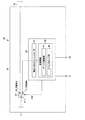
図1は、実施例1に係るUSB中継装置の回路構成を示すブロック図の例である。実施例1は、接続切替え部が、USBクライアント側に設けられた1系統の高速のアナログスイッチからなる例であり、アダプタ構成となっている。
[Example 1]
FIG. 1 is an example of a block diagram illustrating a circuit configuration of the USB relay device according to the first embodiment. The first embodiment is an example in which the connection switching unit includes one high-speed analog switch provided on the USB client side, and has an adapter configuration.
図1に示すように、実施例1に係るUSB中継装置10は、第1コネクタ部11、第2コネクタ部12、発光部13及び報知部14を筺体15の外壁部に備えている。実施例1に係るUSB中継装置10はさらに、第1スイッチ部21及び制御部22を筺体15の内部に備えている。
As illustrated in FIG. 1, the
第1コネクタ部11は、USBクライアント、例えばUSB大容量ストレージや他のUSBデバイスが接続されるUSBコネクタメスである。他のUSBデバイスとしては、キーボードやマウス、プリンタなどのデバイス(機器)を例示することができる。第2コネクタ部12は、USBホストコントローラ、例えばコンピュータのUSBポートに接続されるUSBコネクタオスである。
The
発光部13は、例えばLED(発光ダイオード)からなり、LEDを点灯あるいは点滅させることによってウイルスが検出されたことをユーザに通知する。報知部14は、例えばスピーカやブザーからなり、スピーカからの通知音の出力あるいはブザーの鳴動によってウイルスが検出されたことをユーザに通知する。これらの通知は、制御部22による制御の下に実行される。
The
第1スイッチ部21は、可動接点21_1及び2つの固定接点21_2,21_3を有するアナログスイッチからなり、可動接点21_1が第1コネクタ部11に電気的に接続されている。固定接点21_2は、第2コネクタ部12に電気的に接続されている。固定接点21_3は、制御部22に電気的に接続されている。以下、便宜上、一方の固定接点21_2を接点aと記述し、他方の固定接点21_3を接点bと記述する場合がある。
The
制御部22は、例えば、CPU(Central Processing Unit)、CPUが実行するプログラム等を記憶するためのROM(Read Only Memory)及びCPUの作業領域として使用されるRAM(Random Access Memory)を有する周知のマイクロコンピュータからなる。制御部22は、擬似USBホストコントローラ31及び記憶領域32を内部に有し、スイッチ制御信号CN1によって第1スイッチ部21の切替え制御を行う。
The
擬似USBホストコントローラ31は、制御部22の機能部の一つであり、CPUがROMに記憶されている汎用のプログラムを実行することによって実現される。擬似USBホストコントローラ31は、その入力端が第1スイッチ部21の固定接点21_3に電気的に接続されている。
The pseudo
記憶領域32は、デバイス側領域41及びウイルスチェック部(領域)42がRAM上に展開された構成となっている。ウイルスチェック部42には、ウイルス対策のためにあらかじめインストールされたウイルスチェックソフトウェアが格納されている。そして、ウイルスチェック部42は、制御部22による制御の下に、第1コネクタ部11及び第2コネクタ部12を通して入出力されるファイル、換言すればUSBクライアントとUSBホストコントローラとの間でやり取りされるファイルのウイルスチェックを行う。
The
上記構成の実施例1に係るUSB中継装置10において、第1スイッチ部21は、第1コネクタ部11と第2コネクタ部12との間の接続と、第1コネクタ部11とウイルスチェック機能を有する制御部(ウイルスチェック部)22との間の接続とを選択的に切り替える接続切替え部を構成している。
In the
続いて、実施例1に係るUSB中継装置10の動作について説明する。ここでは、ファイル経由でのウイルス混入の可能性があるUSB大容量ストレージを特定のデバイスとして想定している。後述する実施例においても同様である。
Subsequently, an operation of the
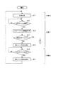
図2は、実施例1に係るUSB中継装置10の動作の流れを示すフローチャートの例(その1)である。図3は、実施例1に係るUSB中継装置10の動作の流れを示すフローチャートの例(その2)である。
FIG. 2 is an example (part 1) of a flowchart illustrating the flow of the operation of the
図2及び図3の各フローチャートに沿って、実施例1に係るUSB中継装置10の動作について、以下に具体的に説明する。なお、以下に説明するUSB中継装置10の一連の動作は、基本的に、マイクロコンピュータからなる制御部22による制御の下に実行される。後述する実施例においても同様である。
The operation of the
(初期状態)
上記構成の実施例1に係るUSB中継装置10において、USBコネクタオスである第2コネクタ部12が、USBホストコントローラの一例であるコンピュータのUSBポートに接続されると、第2コネクタ部12を経由してコンピュータからUSB中継装置10に電源が供給される。このとき、図1に示すように、第1スイッチ部21の可動接点21_1が固定接点21_3(接点b)側に接続された状態となる。この状態がUSB中継装置10の初期状態であり、状態10とする(ステップS11)。
(initial state)
In the
状態10では、USBコネクタメスである第1コネクタ部11に、USBクライアントの一例であるUSBデバイスが接続されても、第1コネクタ部11と第2コネクタ部12との間は電気的に遮断された状態にある。したがって、コンピュータはUSBデバイスと電気的に接続されないため、コンピュータのセキュリティは保たれた状態にある。
In
(USBデバイスが特定のデバイスでない場合)
制御部22は、第1コネクタ部11にUSBデバイスが接続されたか否かを判断し(ステップS12)、USBデバイスが接続されたことを検知すると(S12のYES)、擬似USBホストコントローラ31とUSBデバイスとの間で通信を行う。この通信により、擬似USBホストコントローラ31は、USBの通信プロトコルに従って、USBデバイスの種類(例えば、デバイスタイプやインタフェースタイプ)の情報を取得する(ステップS13)。
(If the USB device is not a specific device)
The
ここで、デバイスタイプやインタフェースタイプの情報から、USBデバイスの種類、即ちUSBデバイスが特定のデバイス(本例では、USB大容量ストレージ)であるか、他のUSBデバイスであるかを判断することができる。そこで、制御部22は、ステップS13で取得したUSBデバイスの種類の情報に基づいて、第1コネクタ部11に接続されたUSBデバイスが特定のデバイスであるか否かを判断する(ステップS14)。
Here, from the information of the device type and the interface type, it is possible to determine the type of the USB device, that is, whether the USB device is a specific device (in this example, a USB large-capacity storage) or another USB device. it can. Therefore, the
ステップS14において、第1コネクタ部11に接続されたUSBデバイスが特定のデバイスでないと判断した場合(S14のNO)、即ちキーボードやマウス、プリンタなどのUSBデバイスである場合、制御部22は、スイッチ制御信号CN1によって第1スイッチ部21の切替え制御を行う(ステップS15)。この第1スイッチ部21の切替え制御により、第1スイッチ部21の可動接点21_1が固定接点21_2(接点a)側に接続された状態となる。ここで、ステップS12からステップS15までの状態を状態11とし、第1スイッチ部21が固定接点21_2(接点a)側に切り替わった状態が図4に示す状態である。
If it is determined in step S14 that the USB device connected to the
図4は、実施例1に係るUSB中継装置10においてUSBデバイスとコンピュータとが直結された状態を示すブロック図の例である。図4に示す状態では、キーボードやマウス、プリンタなど、特定のデバイスであるUSB大容量ストレージ以外のUSBデバイスは、第1コネクタ部11→第1スイッチ部21→第2コネクタ部12の経路でコンピュータと直結された状態となる。ここで再度、コンピュータからUSBの通信プロトコルに従って接続処理が行われる。これにより、特定のデバイス以外のUSBデバイスがコンピュータから使用可能な状態となる。
FIG. 4 is an example of a block diagram illustrating a state in which the USB device and the computer are directly connected in the
その後、制御部22は、第1コネクタ部11からUSBデバイスが抜去されたか否かを判断し(ステップS16)、USBデバイスが抜去されたことを検知すると(S16のYES)、スイッチ制御信号CN1によって第1スイッチ部21の切替え制御を行い(ステップS17)、しかる後ステップS11に戻る。この第1スイッチ部21の切替え制御により、第1スイッチ部21の可動接点21_1が固定接点21_3(接点b)側に切り替えられた状態(図1に示す状態)となる。ここで、ステップS16及びステップS17の状態を状態12とする。
Thereafter, the
(USBデバイスが特定のデバイスである場合)
ステップS14において、第1コネクタ部11に接続されたUSBデバイスが特定のデバイスであると判断した場合(S14のYES)、制御部22は、擬似USBホストコントローラ31の機能により、USBデバイスから第1スイッチ部21を介してファイルを取得し、記憶領域32のデバイス側領域41に書き込む(ステップS18)。次に、制御部22は、デバイス側領域41に書き込まれたファイルを、ウイルスチェック部42に格納されているウイルスチェックソフトウェアを使用してウイルスチェックを行い(ステップS19)、次いで、ウイルスが検出されたか否かを判断する(ステップS20)。
(When the USB device is a specific device)
In step S14, when it is determined that the USB device connected to the
そして、ウイルスが検出されなければ(S20のNO)、制御部22は、スイッチ制御信号CN1によって第1スイッチ部21の切替え制御を行う(ステップS21)。この第1スイッチ部21の切替え制御により、第1スイッチ部21の可動接点21_1が固定接点21_2(接点a)側に切り替えられた状態(図4に示す状態)となる。ここで、ステップS18からステップS20までの状態を状態11とする。
If no virus is detected (NO in S20), the
図4に示す状態では、特定のデバイスであるUSB大容量ストレージは、第1コネクタ部11→第1スイッチ部21→第2コネクタ部12の経路でコンピュータと直結された状態となる。ここで再度、コンピュータからUSBの通信プロトコルに従って接続処理が行われることで、USB大容量ストレージがコンピュータから使用可能な状態となる。
In the state illustrated in FIG. 4, the USB mass storage, which is a specific device, is in a state of being directly connected to the computer via the path of the
その後、制御部22は、第1コネクタ部11からUSBデバイスが抜去されたか否かを判断し(ステップS22)、USBデバイスが抜去されたことを検知すると(S22のYES)、実施例1に係るUSB中継装置10の一連の動作を終了する。
Thereafter, the
ステップS20において、ウイルスが検出された場合(S20のYES)、制御部22は、ウイルスが検出されたことをユーザに知らせるために、発光部13の例えばLEDを点灯させ(ステップS23)、次いで、報知部14の例えばスピーカから通知音を出力する(ステップS24)。
If a virus is detected in step S20 (YES in S20), the
ここでは、発光部13において、LEDを点灯させるとしたが、これに限られるものではなく、特定パターンで点滅させるようにしてもよい。また、報知部14において、スピーカから通知音を出力するとしたが、これに限られるものではなく、ブザーを鳴動させるようにしてもよい。後述する実施例においても同様である。その後、制御部22は、第1コネクタ部11からUSBデバイスが抜去されたか否かを判断する(ステップS25)。ここで、ステップS23からステップS25までの状態を状態11とする。
Here, the LED is turned on in the
そして、USBデバイスが抜去されたことを検知すると(S25のYES)、制御部22は、発光部13を消灯し(ステップS26)、次いで、通知音の出力を停止し(ステップS27)、実施例1に係るUSB中継装置10の一連の動作を終了する。ここで、ステップS26及びステップS27の状態を状態10とする。
Then, when detecting that the USB device has been removed (YES in S25), the
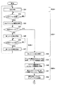
図5は、実施例1に係るUSB中継装置10における状態遷移を示す図の例である。図5には、図2及び図3の各フローチャートの状態10、状態11及び状態12における第1コネクタ部11、第2コネクタ部12及び第1スイッチ部21の状態遷移、ならびに、USBクライアント側とUSBホストコントローラ側の接続状態を示している。
FIG. 5 is an example of a diagram illustrating a state transition in the
状態10では、第2コネクタ部12がホストコントローラに接続、第1コネクタ部11が非接続、第1スイッチ部21が接点b(固定接点21_3)側、USBクライアント側とUSBホストコントローラ側が非接続の状態となる。状態11では、第2コネクタ部12がホストコントローラに接続、第1コネクタ部11がUSBデバイスに接続、第1スイッチ部21が接点b(固定接点21_3)側、しかる後接点a(固定接点21_2)側、USBクライアント側とUSBホストコントローラ側が非接続、しかる後接続(直結)の状態となる。
In
状態12では、第2コネクタ部12がホストコントローラに接続、第1コネクタ部11がUSBデバイスに接続、第1スイッチ部21が接点a(固定接点21_2)側、しかる後接点b(固定接点21_3)側、USBクライアント側とUSBホストコントローラ側とが接続(直結)、しかる後非接続の状態となる。
In
上述したように、実施例1に係るUSB中継装置10は、第1コネクタ部11に接続されるUSBデバイスの種類を確認し、USB大容量ストレージであれば中身を全てチェックし、コンピュータに対するUSB大容量ストレージの接続の可否を判断するアダプタ構成となっている。このUSB中継装置10によれば、コンピュータからUSB大容量ストレージへコピーするファイルの中身についてはチェックできないものの、USB大容量ストレージからコンピュータへコピーするファイルの中身についてはチェックできる。
As described above, the
しかも、接続切替え部として第1スイッチ部21を内蔵し、第1コネクタ部11に接続されたUSBデバイスがUSB大容量ストレージ以外であれば、当該USBデバイスをコンピュータに直結する構成となっているため、USB大容量ストレージだけでなく、キーボードやマウス、プリンタなどの他のUSBデバイスの使用にも対応することができる。また、発光部13及び報知部14を備えているため、ウイルスが検出されたことをユーザに認識させることができる。
Moreover, since the
[実施例2]
図6は、実施例2に係るUSB中継装置の回路構成を示すブロック図の例である。実施例2は、接続切替え部が、USBクライアント側及びUSBホストコントローラ側それぞれに設けられた2系統の高速のアナログスイッチからなる例であり、アダプタ構成となっている。
[Example 2]
FIG. 6 is an example of a block diagram illustrating a circuit configuration of the USB relay device according to the second embodiment. The second embodiment is an example in which the connection switching unit includes two high-speed analog switches provided on the USB client side and the USB host controller side, respectively, and has an adapter configuration.
図6に示すように、実施例2に係るUSB中継装置10は、筺体15の内部に、第1スイッチ部21及び制御部22に加えて第2スイッチ部23を備えており、それ以外の構成は、基本的に、実施例1に係るUSB中継装置10と同じである。
As illustrated in FIG. 6, the
第2スイッチ部23は、可動接点23_1及び2つの固定接点23_2,23_3を有する高速のアナログスイッチからなり、可動接点23_1が第2コネクタ部12に電気的に接続されている。また、第2スイッチ部23の固定接点23_2と第1スイッチ部21の固定接点21_2とが互いに電気的に接続され、固定接点23_3が制御部22に電気的に接続されている。以下、便宜上、一方の固定接点23_2を接点aと記述し、他方の固定接点23_3を接点bと記述する場合がある。
The
制御部22は、擬似USBホストコントローラ31及び記憶領域32に加えて、擬似USBデバイス33を内部に有し、スイッチ制御信号CN1によって第1スイッチ部21の切替え制御を行うとともに、スイッチ制御信号CN2によって第2スイッチ部23の切替え制御を行う。
The
擬似USBデバイス33は、制御部22の機能部の一つであり、CPUがROMに記憶されている汎用のプログラムを実行することによって実現される。擬似USBデバイス33は、その出力端が第2スイッチ部23の固定接点23_3(接点b)に電気的に接続されている。記憶領域32は、デバイス側領域41及びウイルスチェック部42に加えて、コントローラ側領域43を有し、これらの領域がRAM上に展開されている。
The
上記構成の実施例2に係るUSB中継装置10において、第1スイッチ部21及び第2スイッチ部23は、接続切替え部を構成している。そして、当該接続切替え部は、第1コネクタ部11と第2コネクタ部12との間の接続、第1コネクタ部11とウイルスチェック機能を有する制御部(ウイルスチェック部)22との間の接続、及び、第2コネクタ部12と制御部22との間の接続を選択的に切り替える。
In the
続いて、実施例2に係るUSB中継装置10の動作について説明する。
Subsequently, an operation of the
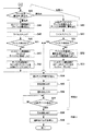
図7は、実施例2に係るUSB中継装置10の動作の流れを示すフローチャートの例(その1)である。図8は、実施例2に係るUSB中継装置10の動作の流れを示すフローチャートの例(その2)である。図7及び図8の各フローチャートに沿って、本実施形態に係るUSB中継装置10の動作について、以下に具体的に説明する。
FIG. 7 is an example (part 1) of a flowchart illustrating the flow of the operation of the
(初期状態)
上記構成の実施例2に係るUSB中継装置10において、USBコネスタオスである第2コネクタ部12が、USBホストコントローラの一例であるコンピュータのUSBポートに接続されると、第2コネクタ部12を経由してコンピュータからUSB中継装置10に電源が供給される。このとき、図6に示すように、第1スイッチ部21の可動接点21_1が固定接点21_3側に接続された状態となり、第2スイッチ部23の可動接点23_1が固定接点23_2側に接続された状態となる。この状態がUSB中継装置10の初期状態であり、状態20とする(ステップS31)。
(initial state)
In the
状態20では、USBコネクタメスである第1コネクタ部11に、USBクライアントの一例であるUSBデバイスが接続されても、第1コネクタ部11と第2コネクタ部12との間は電気的に遮断された状態にある。したがって、コンピュータはUSBデバイスと電気的に接続されないため、コンピュータのセキュリティは保たれた状態にある。
In the
(USBデバイスが特定のデバイスでない場合)
制御部22は、第1コネクタ部11にUSBデバイスが接続されたか否かを判断し(ステップS32)、USBデバイスが接続されたことを検知すると(S32のYES)、擬似USBホストコントローラ31とUSBデバイスとの間で通信を行う。この通信により、擬似USBホストコントローラ31は、USBの通信プロトコルに従って、USBデバイスの種類(例えば、デバイスタイプやインタフェースタイプ)の情報を取得する(ステップS33)。
(If the USB device is not a specific device)
The
次に、制御部22は、ステップS33で取得したUSBデバイスの種類の情報に基づいて、第1コネクタ部11に接続されたUSBデバイスが特定のデバイス(本例では、USB大容量ストレージ)であるか否かを判断する(ステップS34)。
Next, the
ステップS34において、第1コネクタ部11に接続されたUSBデバイスが特定のデバイスでないと判断した場合(S34のNO)、制御部22は、スイッチ制御信号CN1によって第1スイッチ部21の切替え制御を行う(ステップS15)。この第1スイッチ部21の切替え制御により、第1スイッチ部21の可動接点21_1が固定接点21_2(接点a)側に接続された状態となる。ここで、ステップS32からステップS35までの状態を状態21とし、第1スイッチ部21が固定接点21_2(接点a)側に切り替わった状態が図9に示す状態である。
In step S34, when it is determined that the USB device connected to the
図9は、USBデバイスが特定のデバイスでない場合の実施例2に係るUSB中継装置10の動作を説明するためのブロック図の例である。図9に示す状態では、キーボードやマウス、プリンタなど、特定のデバイスであるUSB大容量ストレージ以外のUSBデバイスは、第1コネクタ部11→第1スイッチ部21→第2スイッチ部23→第2コネクタ部12の経路でコンピュータと直結された状態となる。ここで再度、コンピュータからUSBの通信プロトコルに従って接続処理が行われる。これにより、特定のデバイス以外のUSBデバイスがコンピュータから使用可能な状態となる。
FIG. 9 is an example of a block diagram for explaining the operation of the
その後、制御部22は、第1コネクタ部11からUSBデバイスが抜去されたか否かを判断し(ステップS36)、USBデバイスが抜去されたことを検知すると(S36のYES)、スイッチ制御信号CN1によって第1スイッチ部21の切替え制御を行い(ステップS37)、しかる後ステップS31に戻る。この第1スイッチ部21の切替え制御により、第1スイッチ部21の可動接点21_1が固定接点21_3(接点b)側に切り替えられた状態(図6に示す状態)となる。ここで、ステップS36及びステップS37の状態を状態22とする。
Thereafter, the
(USBデバイスが特定のデバイスである場合)
ステップS34において、USBデバイスが特定のデバイスであると判断した場合(S34のYES)、制御部22は、スイッチ制御信号CN2によって第2スイッチ部23の切替え制御を行う(ステップS38)。この切替え制御により、第2スイッチ部23の可動接点23_1が固定接点23_3(接点b)側に切り替えられた状態となる。この状態が図10に示す状態である。ここで、ステップS32からステップS38まで(ステップS36及びステップS37を除く)の状態を状態21とする。
(When the USB device is a specific device)
If it is determined in step S34 that the USB device is a specific device (YES in S34), the
図10は、USBデバイスが特定のデバイスであった場合のUSB中継装置10の動作を説明するためのブロック図の例である。状態21では、USBデバイスは、第1コネクタ部11→第1スイッチ部21の経路で、制御部22の擬似USBホストコントローラ31に接続される。また、コンピュータは、第2コネクタ部12→第2スイッチ部23の経路で、制御部22の擬似USBデバイス33に接続される。ここで、擬似USBホストコントローラ31と擬似USBデバイス33とは、制御部22の記憶領域32を経由してファイルのやり取りが可能なため、USBデバイスとコンピュータとは間接的に接続された状態にある。
FIG. 10 is an example of a block diagram for explaining the operation of the
この間接接続の状態において、制御部22は、擬似USBホストコントローラ31により、USBデバイスから第1スイッチ部21を介してファイルシステムのディレクトリ構造を取得し、記憶領域32のデバイス側領域41に反映する(ステップS39)。次に、制御部22は、デバイス側領域41に反映されたファイルシステムのディレクトリ構造をコントローラ側領域43に反映する(ステップS40)。
In this indirect connection state, the
次に、制御部22は、擬似USBデバイス33をUSB大容量ストレージとして有効化し(ステップS41)、次いで、USB大容量ストレージとして有効化された擬似USBデバイス33と、USBホストコントローラ(コンピュータ)とを第2スイッチ部23を通して接続する(ステップS42)。
Next, the
次に、制御部22は、USBホストコントローラの要求が、USB大容量ストレージへのファイルの書込みであるか、USB大容量ストレージからのファイルの読込みであるかを判断する(ステップS43)。そして、ファイルの書込みである場合は、制御部22は、擬似USBデバイス33の機能により、USBホストコントローラの要求に従い、記憶領域32のコントローラ側領域43に書き込む(ステップS44)。
Next, the
次に、制御部22は、記憶領域32のコントローラ側領域43に書き込まれたファイルを、ウイルスチェック部42に格納されているウイルスチェックソフトウェアを使用してウイルスチェックを行い(ステップS45)、次いで、ウイルスが検出されたか否かを判断する(ステップS46)。
Next, the
ステップS46において、ウイルスが検出されない場合(S46のNO)、制御部22は、記憶領域32のコントローラ側領域43に書き込まれたファイルを、デバイス側領域41にコピーする(ステップS47)。次に、制御部22は、デバイス側領域41にコピーされたファイルをUSBデバイス(USB大容量ストレージ)にコピーし(ステップS48)、しかる後ステップS43に戻る。
If no virus is detected in step S46 (NO in S46), the
ステップS43において、USBホストコントローラの要求が、USB大容量ストレージからのファイルの読込みである場合、制御部22は、USBデバイス(USB大容量ストレージ)からファイルを読み込み、記憶領域32のデバイス側領域41に書き込む(ステップS49)。次に、制御部22は、記憶領域32のデバイス側領域41に書き込まれたファイルを、ウイルスチェック部42に格納されているウイルスチェックソフトウェアを使用してウイルスチェックを行い(ステップS50)、次いで、ウイルスが検出されたか否かを判断する(ステップS51)。
In step S43, when the request of the USB host controller is to read a file from the USB mass storage, the
ステップS51において、ウイルスが検出されない場合(S51のNO)、制御部22は、記憶領域32のデバイス側領域41に書き込まれたファイルを、コントローラ側領域43にコピーする(ステップS52)。次に、制御部22は、コントローラ側領域43にコピーされたファイルをUSBホストコントローラ(コンピュータ)にコピーし(ステップS53)、しかる後ステップS43に戻る。ここで、ステップS39からステップS53までの状態を状態23とする。
If no virus is detected in step S51 (NO in S51), the
ステップS46/ステップS51において、ウイルスが検出された場合(S46のYES/S51のYES)、制御部22は、スイッチ制御信号CN2によって第2スイッチ部23の切替え制御を行う(ステップS54)。この切替え制御により、第2スイッチ部23の可動接点23_1が固定接点23_2(接点a)側に切り替えられた状態となる。
When a virus is detected in step S46 / step S51 (YES in S46 / YES in S51), the
次に、制御部22は、ウイルスが検出されたことをユーザに知らせるために、発光部13の例えばLEDを点灯させ(ステップS55)、次いで、報知部14の例えばスピーカから通知音を出力する(ステップS56)。その後、制御部22は、第1コネクタ部11からUSBデバイスが抜去されたか否かを判断する(ステップS57)。ここで、ステップS55からステップS57までの状態を状態21とする。
Next, the
そして、USBデバイスが抜去されたことを検知すると(S57のYES)、制御部22は、発光部13を消灯し(ステップS58)、次いで、通知音の出力を停止し(ステップS59)、実施例2に係るUSB中継装置10の一連の動作を終了する。ここで、ステップS58及びステップS59の状態を状態20とする。
Then, when detecting that the USB device has been removed (YES in S57), the
図11は、実施例2に係るUSB中継装置10における状態遷移を示す図の例である。図11には、図7及び図8の各フローチャートの状態20、状態21、状態22及び状態23における第1コネクタ部11、第2コネクタ部12、第1スイッチ部21及び第2スイッチ部23の状態遷移、ならびに、USBクライアント側とUSBホストコントローラ側の接続状態を示している。
FIG. 11 is an example of a diagram illustrating a state transition in the
状態20では、第2コネクタ部12がホストコントローラに接続、第1コネクタ部11が非接続、第1スイッチ部21が接点b(固定接点21_3)側、第2スイッチ部23が接点a(固定接点23_2)側、USBクライアント側とUSBホストコントローラ側が非接続の状態となる。
In
状態21では、第2コネクタ部12がホストコントローラに接続、第1コネクタ部11がUSBデバイスに接続、第1スイッチ部21が接点b(固定接点21_3)側、しかる後接点a(固定接点21_2)側、第2スイッチ部23が接点a(固定接点21_2)側、しかる後接点b(固定接点23_3)側の状態となる。また、USBクライアント側とUSBホストコントローラ側が非接続、しかる後接続(制御部22経由で間接的な接続)の状態となる。
In the
状態22では、第2コネクタ部12がホストコントローラに接続、第1コネクタ部11がUSBデバイスに接続、第1スイッチ部21が接点a(固定接点21_2)側、しかる後接点b(固定接点21_3)側、第2スイッチ部23が接点a(固定接点21_2)側の状態となる。また、USBクライアント側とUSBホストコントローラ側が接続(直結)、しかる後非接続の状態となる。
In the
状態23では、第2コネクタ部12がホストコントローラに接続、第1コネクタ部11がUSBデバイスに接続、第1スイッチ部21が接点b(固定接点21_3)側、第2スイッチ部23が接点b(固定接点23_3)側の状態となる。また、USBクライアント側とUSBホストコントローラ側が接続(制御部22経由で間接的な接続)の状態となる。
In the
上述したように、実施例2に係るUSB中継装置10は、第1コネクタ部11に接続されたUSBデバイスの種類を確認し、USB大容量ストレージであれば、USB大容量ストレージとコンピュータとの間でやり取りするファイルをチェックし、ファイル毎にコピーの可否を判断するアダプタ構成となっている。このUSB中継装置10によれば、コンピュータからUSB大容量ストレージへコピーするファイル、及び、USB大容量ストレージからコンピュータへコピーするファイルの中身についてチェックできる。
As described above, the
また、第1スイッチ部21及び第2スイッチ部23からなる接続切替え部を備えていることで、実施例1に係るUSB中継装置10と同様に、USB大容量ストレージだけでなく、キーボードやマウス、プリンタなどの他のUSBデバイスの使用にも対応することができる。さらに、発光部13及び報知部14を備えているため、ウイルスが検出されたことをユーザに認識させることができる。
In addition, by providing the connection switching unit including the
[実施例3]
図12は、実施例3に係るUSB中継装置の回路構成を示すブロック図の例である。実施例3は、接続切替え部が、USBクライアント側に設けられた1系統のアナログスイッチからなる実施例1に対応した例である。
[Example 3]
FIG. 12 is an example of a block diagram illustrating a circuit configuration of the USB relay device according to the third embodiment. Third Embodiment A third embodiment is an example corresponding to the first embodiment in which the connection switching unit includes one analog switch provided on the USB client side.
図12に示すように、実施例3に係るUSB中継装置10は、USBクライアントが接続される第1コネクタ部(USBポート)として、n個のコネクタ部11_1〜11_nを備えている。これらn個のコネクタ部11_1〜11_nには、種々のUSBデバイス、例えばUSB大容量ストレージの他、キーボードやマウス、プリンタなどの他のUSBデバイスを同時に接続することができる。第1スイッチ部21は、n個のコネクタ部11_1〜11_nに対応して、n個のスイッチ部21_1〜21_nからなる。また、実施例3に係るUSB中継装置10は、USBハブ50を内蔵している。
As illustrated in FIG. 12, the
制御部22は、n個のスイッチ部21_1〜21_nに対応して、n個の擬似USBホストコントローラ31_1〜31_nを有し、また記憶領域32にウイルスチェック部42と共に、n個のデバイス側領域41_1〜41_nを有している。制御部22は、適宜、n個の第1スイッチ部21_1〜21_nの切替え制御を行うことで、n個のコネクタ部11_1〜11_nとUSBハブ50との間の接続、及び、n個のコネクタ部11_1〜11_nとn個の擬似USBホストコントローラ31_1〜31_nとの間の接続を選択的に行う。
The
上述した実施例3に係るUSB中継装置10は、n個のコネクタ部11_1〜11_nの各々に接続されたUSBデバイスの種類を確認し、USB大容量ストレージであれば中身を全てチェックし、コンピュータに対するUSB大容量ストレージの接続の可否を判断するハブ構成となっている。そして、USB大容量ストレージ以外のデバイスの場合は、当該USBデバイスをコンピュータに直結する制御を行う。すなわち、実施例3に係るUSB中継装置10によれば、USB大容量ストレージだけでなく、キーボードやマウス、プリンタなどの他のUSBデバイスの使用にも対応することができる。
The
[実施例4]
図13は、実施例4に係るUSB中継装置の回路構成を示すブロック図の例である。実施例4は、接続切替え部が、USBクライアント側及びUSBホストコントローラ側それぞれに設けられた2系統のアナログスイッチからなる実施例2に対応した例であり、ハブ構成である点では実施例3と同じである。
[Example 4]
FIG. 13 is an example of a block diagram illustrating a circuit configuration of the USB relay device according to the fourth embodiment. The fourth embodiment is an example corresponding to the second embodiment in which the connection switching unit includes two analog switches provided on each of the USB client side and the USB host controller side. Is the same.
図13に示すように、実施例4に係るUSB中継装置10は、実施例3に係るUSB中継装置10の構成要素に加えて、以下の構成要素を備えている。すなわち、第2スイッチ部23は、n個のコネクタ部11_1〜11_nに対応して、n個のスイッチ部23_1〜23_nからなる。また、制御部22は、n個のスイッチ部21_1〜21_nに対応して、n個の擬似USBデバイス33_1〜33_nを有し、また記憶領域32にn個のコントローラ側領域43_1〜43_nを有している。
As illustrated in FIG. 13, the
そして、制御部22は、適宜、n個のスイッチ部21_1〜21_n及びn個のスイッチ部23_1〜23_nの切替え制御を行う。この切替え制御により、n個のコネクタ部11_1〜11_nとUSBハブ50との間の接続、n個のコネクタ部11_1〜11_nとn個の擬似USBホストコントローラ31_1〜31_nとの間の接続、及び、n個の擬似USBデバイス33_1〜33_nとUSBハブ50との間の接続を選択的に行う。
Then, the
上述した実施例4に係るUSB中継装置10は、n個のコネクタ部11_1〜11_nの各々に接続されたUSBデバイスの種類を確認し、USB大容量ストレージであれば、USB大容量ストレージとコンピュータとの間でやり取りするファイルをチェックし、ファイル毎にコピーの可否を判断するハブ構成となっている。そして、USB大容量ストレージ以外のデバイスの場合は、当該USBデバイスをコンピュータに直結する制御を行う。すなわち、実施例4に係るUSB中継装置10によれば、USB大容量ストレージだけでなく、キーボードやマウス、プリンタなどの他のUSBデバイスの使用にも対応することができる。
The
[変形例]
本発明は、上記した実施例に限定されるものではなく、様々な変形例が含まれる。例えば、上記した実施例は本発明を分かりやすく説明するために詳細に説明したものであり、必ずしも説明した全ての構成を備えるものに限定されるものではない。また、本発明は、ある実施例の構成の一部を他の実施例の構成に置き換えることが可能であり、また、ある実施例の構成に他の実施例の構成を加えることも可能である。また、各実施例の構成の一部について、他の構成の追加・削除・置換をすることも可能である。また、上記の各構成や機能部等については、それらの一部または全部を、例えば集積回路で設計する等によってハードウェアで実現してもよい。
[Modification]
The present invention is not limited to the above embodiments, but includes various modifications. For example, the above-described embodiments have been described in detail in order to explain the present invention in an easy-to-understand manner, and are not necessarily limited to those having all the described configurations. Further, in the present invention, a part of the configuration of one embodiment can be replaced with the configuration of another embodiment, and the configuration of another embodiment can be added to the configuration of one embodiment. . Further, for a part of the configuration of each embodiment, it is also possible to add, delete, or replace another configuration. In addition, some or all of the above-described configurations, functional units, and the like may be realized by hardware, for example, by designing an integrated circuit.
また、上記した実施例では、制御部22がウイルスチェック機能(即ち、ウイルスチェック部42)を有する構成としたが、ウイルスチェック部42を制御部22とは別に単独で設ける構成とすることも可能である。また、上記した実施例では、ウイルスが検出されたことをユーザに通知する手段として、発光部13及び報知部14を備える構成としたが、必ずしも発光部13及び報知部14の両方を備える必要はなく、いずれか一方を備える構成としてもよい。
In the above-described embodiment, the
10…USB中継装置、 11…第1コネクタ部、 12…第2コネクタ部、 13…発光部、 14…報知部、 21…第1スイッチ部、 22…制御部、 23…第2スイッチ部、 31…擬似USBホストコントローラ、 32…記憶領域、 33…擬似USBデバイス、 41…デバイス側領域、 42…ウイルスチェック部、 43…コントローラ側領域、 50…USBハブ
DESCRIPTION OF
Claims (5)
USBホストコントローラに接続される第2コネクタ部と、
前記第1コネクタ部及び前記第2コネクタ部を通して入出力されるファイルのウイルスチェックを行うウイルスチェック部と、
前記第1コネクタ部と前記第2コネクタ部との間の接続と、前記第1コネクタ部と前記ウイルスチェック部との間の接続とを選択的に切り替える接続切替え部と、
前記接続切替え部の切替え制御を行う制御部と、を備え、
前記制御部は、前記USBクライアントがUSB大容量ストレージのとき、前記接続切替え部において前記第1コネクタ部と前記ウイルスチェック部との間が接続されるように切替え制御を行い、前記USBクライアントがUSB大容量ストレージ以外のUSBデバイスのとき、前記接続切替え部において前記第1コネクタ部と前記第2コネクタ部との間が接続されるように切替え制御を行う
ことを特徴とするUSB中継装置。 A first connector unit to which a USB client is connected;
A second connector unit connected to the USB host controller;
A virus check unit that performs a virus check on a file input / output through the first connector unit and the second connector unit;
A connection switching unit that selectively switches between a connection between the first connector unit and the second connector unit and a connection between the first connector unit and the virus check unit;
And a control unit which controls switching of the connection switching unit,
The control unit, when the USB client is a USB mass storage, performs switching control so that the connection switching unit connects between the first connector unit and the virus check unit. A USB relay device , wherein when a USB device other than a large-capacity storage is used, the connection switching unit controls switching so that the first connector unit and the second connector unit are connected .
前記制御部は、前記USBクライアントが前記USB大容量ストレージのとき、前記第1スイッチ部の切替え制御によって前記第1コネクタ部と前記ウイルスチェック部との間を電気的に接続するとともに、前記第2スイッチ部の切替え制御によって前記第2コネクタ部と前記ウイルスチェック部との間を電気的に接続する
ことを特徴とする請求項1に記載のUSB中継装置。 The connection switching unit includes a first switch unit having a movable contact connected to the first connector unit, and a second switch unit having a movable contact connected to the second connector unit, and the first switch unit Is connected to one fixed contact of the second switch unit, and one fixed contact of the first switch unit and one fixed contact of the second switch unit are respectively connected to the virus check unit. Connected
The control unit, when the USB client is the USB mass storage, electrically connects the first connector unit and the virus check unit by switching control of the first switch unit, The USB relay device according to claim 1, wherein the switching control of a switch unit electrically connects the second connector unit and the virus check unit .
ことを特徴とする請求項2に記載のUSB中継装置。 When the USB client is a USB device other than the USB mass storage, the control unit controls the switching between the first switch unit and the second switch unit to switch between the first connector unit and the second connector unit. The USB relay device according to claim 2, wherein the USB relay device is electrically connected.
ことを特徴とする請求項1に記載のUSB中継装置。 The USB relay device according to claim 1 , further comprising at least one of a light emitting unit and a notifying unit that notify that a virus has been detected when the virus check unit detects a virus .
USBホストコントローラに接続される第2コネクタ部と、
前記第1コネクタ部及び前記第2コネクタ部を通して入出力されるファイルのウイルスチェックを行うウイルスチェック部と、
前記第1コネクタ部と前記第2コネクタ部との間の接続と、前記第1コネクタ部と前記ウイルスチェック部との間の接続とを選択的に切り替える接続切替え部と
前記接続切替え部の切替え制御を行う制御部と
を備えるUSB中継装置の制御方法であって、
前記制御部は、前記USBクライアントがUSB大容量ストレージのとき、前記接続切替え部において前記第1コネクタ部と前記ウイルスチェック部との間が接続されるように切替え制御を行い、前記USBクライアントがUSB大容量ストレージ以外のUSBデバイスのとき、前記接続切替え部において前記第1コネクタ部と前記第2コネクタ部との間が接続されるように切替え制御を行う
ことを特徴とするUSB中継装置の制御方法。 A first connector unit to which a USB client is connected;
A second connector unit connected to the USB host controller;
A virus check unit that performs a virus check on a file input / output through the first connector unit and the second connector unit;
A connection switching unit that selectively switches between a connection between the first connector unit and the second connector unit and a connection between the first connector unit and the virus check unit;
A control unit for performing switching control of the connection switching unit;
A method for controlling a USB relay device comprising:
The control unit, when the USB client is a USB mass storage, performs switching control so that the connection switching unit connects between the first connector unit and the virus check unit. when a USB device other than mass storage, the U SB repeater you and performs the switching control so is connected between said second connector portion and the first connector part in the connection switching unit Control method .
Priority Applications (2)
| Application Number | Priority Date | Filing Date | Title |
|---|---|---|---|
| JP2016214806A JP6625035B2 (en) | 2016-11-02 | 2016-11-02 | USB relay device and control method of USB relay device |
| PCT/JP2017/038444 WO2018084038A1 (en) | 2016-11-02 | 2017-10-25 | Usb repeater and method for controlling usb repeater |
Applications Claiming Priority (1)
| Application Number | Priority Date | Filing Date | Title |
|---|---|---|---|
| JP2016214806A JP6625035B2 (en) | 2016-11-02 | 2016-11-02 | USB relay device and control method of USB relay device |
Publications (3)
| Publication Number | Publication Date |
|---|---|
| JP2018073260A JP2018073260A (en) | 2018-05-10 |
| JP2018073260A5 JP2018073260A5 (en) | 2019-03-14 |
| JP6625035B2 true JP6625035B2 (en) | 2019-12-25 |
Family
ID=62076810
Family Applications (1)
| Application Number | Title | Priority Date | Filing Date |
|---|---|---|---|
| JP2016214806A Active JP6625035B2 (en) | 2016-11-02 | 2016-11-02 | USB relay device and control method of USB relay device |
Country Status (2)
| Country | Link |
|---|---|
| JP (1) | JP6625035B2 (en) |
| WO (1) | WO2018084038A1 (en) |
Family Cites Families (3)
| Publication number | Priority date | Publication date | Assignee | Title |
|---|---|---|---|---|
| JP4009315B1 (en) * | 2007-02-14 | 2007-11-14 | 有限会社トゥールビヨン | Security adapter |
| JP5149039B2 (en) * | 2008-03-05 | 2013-02-20 | 新光電気工業株式会社 | Virus check device and data communication method using the same |
| JP2011221628A (en) * | 2010-04-06 | 2011-11-04 | Renesas Electronics Corp | Security adapter |
-
2016
- 2016-11-02 JP JP2016214806A patent/JP6625035B2/en active Active
-
2017
- 2017-10-25 WO PCT/JP2017/038444 patent/WO2018084038A1/en not_active Ceased
Also Published As
| Publication number | Publication date |
|---|---|
| JP2018073260A (en) | 2018-05-10 |
| WO2018084038A1 (en) | 2018-05-11 |
Similar Documents
| Publication | Publication Date | Title |
|---|---|---|
| JP6625077B2 (en) | Virus detection system and virus detection method using USB relay device | |
| US11669322B2 (en) | Firmware upgrade method and apparatus | |
| US9015458B2 (en) | Computer system and method for updating basic input/output system by switching between local mode and bypass mode through baseboard management controller | |
| KR102297321B1 (en) | A proxy device and a device in a chassis, and an operating method of the proxy device | |
| KR102277412B1 (en) | A self-configuring baseboard management controller and an operating method thereof | |
| US8204971B2 (en) | Systems and methods for dynamically configuring node behavior in a sensor network | |
| JP5915086B2 (en) | Switching control device, switching control method, information processing device, and switching control program | |
| JP6237406B2 (en) | Information processing apparatus, storage system, and program | |
| US20100274986A1 (en) | Control apparatus and control method therefor | |
| JP2009043081A (en) | Maintenance management system, database sever, maintenance management program, and maintenance management method | |
| JP7572483B2 (en) | STORAGE SYSTEM AND METHOD FOR SWITCHING OPERATION MODE OF STORAGE SYSTEM - Patent application | |
| JP6625076B2 (en) | USB management system and USB management method using USB relay device | |
| CN118427020A (en) | Hardware equipment management method, device, BMC, storage medium and program product | |
| JP6625035B2 (en) | USB relay device and control method of USB relay device | |
| JP5868563B1 (en) | Control device and unit for distributed control system | |
| US10223296B2 (en) | Method of transferring configuration information for a connected object | |
| JP2015053555A (en) | Data transfer apparatus and data transfer method | |
| CN116954635A (en) | Flash memory chip burning method and system, storage medium and electronic equipment | |
| JP2014182604A (en) | Information processing device and control method | |
| CN116028430B (en) | Scanning method of pcie equipment and system-on-chip | |
| JP5771167B2 (en) | Monitoring system, transmission apparatus, and monitoring control method | |
| JP6031757B2 (en) | Transponder, its control method and control program | |
| WO2015011895A1 (en) | Information processing device, i/o system, and i/o control method | |
| AU2016201734B2 (en) | Alarm assembly and programming key | |
| Busatto | TCP Keepalive HOWTO |
Legal Events
| Date | Code | Title | Description |
|---|---|---|---|
| A521 | Written amendment |
Free format text: JAPANESE INTERMEDIATE CODE: A523 Effective date: 20190131 |
|
| A621 | Written request for application examination |
Free format text: JAPANESE INTERMEDIATE CODE: A621 Effective date: 20190131 |
|
| A131 | Notification of reasons for refusal |
Free format text: JAPANESE INTERMEDIATE CODE: A131 Effective date: 20190903 |
|
| A521 | Written amendment |
Free format text: JAPANESE INTERMEDIATE CODE: A523 Effective date: 20191023 |
|
| TRDD | Decision of grant or rejection written | ||
| A01 | Written decision to grant a patent or to grant a registration (utility model) |
Free format text: JAPANESE INTERMEDIATE CODE: A01 Effective date: 20191112 |
|
| A61 | First payment of annual fees (during grant procedure) |
Free format text: JAPANESE INTERMEDIATE CODE: A61 Effective date: 20191126 |
|
| R150 | Certificate of patent or registration of utility model |
Ref document number: 6625035 Country of ref document: JP Free format text: JAPANESE INTERMEDIATE CODE: R150 |