JP6624834B2 - Imaging device and control method thereof - Google Patents
Imaging device and control method thereof Download PDFInfo
- Publication number
- JP6624834B2 JP6624834B2 JP2015152694A JP2015152694A JP6624834B2 JP 6624834 B2 JP6624834 B2 JP 6624834B2 JP 2015152694 A JP2015152694 A JP 2015152694A JP 2015152694 A JP2015152694 A JP 2015152694A JP 6624834 B2 JP6624834 B2 JP 6624834B2
- Authority
- JP
- Japan
- Prior art keywords
- image
- amount
- pairs
- image signals
- calculating
- Prior art date
- Legal status (The legal status is an assumption and is not a legal conclusion. Google has not performed a legal analysis and makes no representation as to the accuracy of the status listed.)
- Active
Links
Images


Classifications
-
- H—ELECTRICITY
- H04—ELECTRIC COMMUNICATION TECHNIQUE
- H04N—PICTORIAL COMMUNICATION, e.g. TELEVISION
- H04N25/00—Circuitry of solid-state image sensors [SSIS]; Control thereof
- H04N25/70—SSIS architectures; Circuits associated therewith
- H04N25/703—SSIS architectures incorporating pixels for producing signals other than image signals
- H04N25/704—Pixels specially adapted for focusing, e.g. phase difference pixel sets
-
- H—ELECTRICITY
- H04—ELECTRIC COMMUNICATION TECHNIQUE
- H04N—PICTORIAL COMMUNICATION, e.g. TELEVISION
- H04N23/00—Cameras or camera modules comprising electronic image sensors; Control thereof
- H04N23/60—Control of cameras or camera modules
- H04N23/617—Upgrading or updating of programs or applications for camera control
-
- H—ELECTRICITY
- H04—ELECTRIC COMMUNICATION TECHNIQUE
- H04N—PICTORIAL COMMUNICATION, e.g. TELEVISION
- H04N23/00—Cameras or camera modules comprising electronic image sensors; Control thereof
- H04N23/60—Control of cameras or camera modules
- H04N23/67—Focus control based on electronic image sensor signals
- H04N23/672—Focus control based on electronic image sensor signals based on the phase difference signals
-
- H—ELECTRICITY
- H04—ELECTRIC COMMUNICATION TECHNIQUE
- H04N—PICTORIAL COMMUNICATION, e.g. TELEVISION
- H04N23/00—Cameras or camera modules comprising electronic image sensors; Control thereof
- H04N23/60—Control of cameras or camera modules
- H04N23/69—Control of means for changing angle of the field of view, e.g. optical zoom objectives or electronic zooming
-
- H—ELECTRICITY
- H04—ELECTRIC COMMUNICATION TECHNIQUE
- H04N—PICTORIAL COMMUNICATION, e.g. TELEVISION
- H04N25/00—Circuitry of solid-state image sensors [SSIS]; Control thereof
- H04N25/10—Circuitry of solid-state image sensors [SSIS]; Control thereof for transforming different wavelengths into image signals
- H04N25/11—Arrangement of colour filter arrays [CFA]; Filter mosaics
- H04N25/13—Arrangement of colour filter arrays [CFA]; Filter mosaics characterised by the spectral characteristics of the filter elements
- H04N25/134—Arrangement of colour filter arrays [CFA]; Filter mosaics characterised by the spectral characteristics of the filter elements based on three different wavelength filter elements
Landscapes
- Engineering & Computer Science (AREA)
- Multimedia (AREA)
- Signal Processing (AREA)
- Physics & Mathematics (AREA)
- Spectroscopy & Molecular Physics (AREA)
- Software Systems (AREA)
- Studio Devices (AREA)
- Focusing (AREA)
- Automatic Focus Adjustment (AREA)
- General Physics & Mathematics (AREA)
- Optics & Photonics (AREA)
- General Engineering & Computer Science (AREA)
Description
本発明は撮像装置およびその制御方法に関する。 The present invention relates to an imaging device and a control method thereof.
デジタルカメラのような撮像装置(電子機器が内蔵する撮像装置を含む)は、一般にオートフォーカス(自動焦点検出またはAF)機能を有している。オートフォーカス機能には位相差検出方式とコントラスト検出方式とがある。従来、位相差検出方式は撮像素子とは別のAFセンサが必要であったが、近年では撮像素子から得られる信号を用いた位相差検出方式のオートフォーカス機能が実現され、撮像面位相差AFなどと呼ばれている。 An imaging device such as a digital camera (including an imaging device incorporated in an electronic device) generally has an autofocus (automatic focus detection or AF) function. The autofocus function includes a phase difference detection method and a contrast detection method. Conventionally, the phase difference detection method requires an AF sensor separate from the image sensor, but in recent years, an autofocus function of the phase difference detection method using a signal obtained from the image sensor has been realized, and the image plane phase difference AF has been realized. And so on.
位相差検出方式には、デフォーカス量とデフォーカス方向の両方を同時に検出できるという利点があるが、1対の像信号について相対的なシフト量を変更しながら相関演算を繰り返し実行する必要があるため、演算量が多い。高速な焦点検出や、消費電力低減を実現するため、位相差検出方式における演算量を削減する提案がなされている。 The phase difference detection method has an advantage that both the defocus amount and the defocus direction can be detected at the same time, but it is necessary to repeatedly execute the correlation operation while changing the relative shift amount for a pair of image signals. Therefore, the amount of calculation is large. In order to realize high-speed focus detection and reduction in power consumption, proposals have been made to reduce the amount of calculation in the phase difference detection method.
特許文献1には、1対の像信号のシフト量の絶対値が小さい状態からシフト量を増加させながら相関演算を行い、相関量の極値が検出された時点で相関演算を終了することが開示されている。これにより、シフト範囲全体について演算を行うよりも少ない演算量で相関演算を終了できる可能性が高くなる。
しかしながら、特許文献1に記載の方法では、デフォーカス量が小さい被写体についての極値が検出された時点で相関演算が終了されてしまうため、撮影者の意図する被写体に合焦できない場合があった。
However, in the method described in
本発明はこのような従来技術の課題に鑑みてなされたものである。本発明は、焦点検出するべき被写体のさまざまなデフォーカス状態において、焦点検出のための相関演算量を低減可能な撮像装置およびその制御方法の提供を目的とする。 The present invention has been made in view of such problems of the related art. An object of the present invention is to provide an imaging apparatus capable of reducing the amount of correlation calculation for focus detection in various defocus states of a subject to be focus-detected, and a control method thereof.
上述の目的は、撮像素子から得られる信号に基づいて、複数対の像信号を生成する生成手段と、複数対の像信号の少なくとも1対に関して、相対的に位置をずらしながら演算した相関量に基づいて、像信号のずれ量を検出する演算手段と、演算手段が演算したずれ量に基づいてデフォーカス量を算出する算出手段と、デフォーカス量に基づいてフォーカスレンズの位置を制御する制御手段と、を有し、生成手段は、複数対の像信号として、検出可能なデフォーカス量の範囲と、デフォーカス量の検出精度とが異なる複数の信号対を生成し、演算手段は生成手段が生成した複数対の像信号の各対に関して、同一の被写体が含まれる実質的に同一の視野内でずれ量を検出する、ことを特徴とする撮像装置によって達成される。 The above-described object is to provide a means for generating a plurality of pairs of image signals based on a signal obtained from an image sensor, and a correlation amount calculated while relatively displacing positions of at least one pair of the plurality of pairs of image signals. Calculating means for detecting a shift amount of the image signal based on the shift amount, calculating means for calculating a defocus amount based on the shift amount calculated by the calculating means, and control means for controlling a position of the focus lens based on the defocus amount The generating means generates, as a plurality of pairs of image signals, a plurality of signal pairs having different ranges of detectable defocus amount and detection accuracy of the defocus amount, and the calculating means includes a generating means. An image pickup apparatus is characterized in that, for each pair of the generated plural pairs of image signals, a shift amount is detected within substantially the same field of view including the same subject .
本発明によれば、焦点検出するべき被写体のさまざまなデフォーカス状態において、焦点検出のための相関演算量を低減可能な撮像装置およびその制御方法を提供できる。 According to the present invention, it is possible to provide an imaging apparatus capable of reducing the amount of correlation calculation for focus detection in various defocus states of a subject to be focus-detected, and a control method thereof.
以下、添付図面を参照して本発明の例示的な実施形態について説明する。なお、以下では本発明を撮像装置の一例としてのデジタルカメラに適用した実施形態について説明するが、本発明は位相差検出方式のオートフォーカス機能を有するカメラを備える任意の電子機器に適用することができる。このような電子機器の例には、パーソナルコンピュータ、タブレット端末、ゲーム機、携帯電話機、ロボット、ドライブレコーダ、家電製品などが含まれるが、これらに限定されない。 Hereinafter, exemplary embodiments of the present invention will be described with reference to the accompanying drawings. Hereinafter, an embodiment in which the present invention is applied to a digital camera as an example of an imaging apparatus will be described. However, the present invention can be applied to any electronic apparatus including a camera having an autofocus function of a phase difference detection method. it can. Examples of such electronic devices include, but are not limited to, personal computers, tablet terminals, game consoles, mobile phones, robots, drive recorders, home appliances, and the like.
●(第1の実施形態)
(構成の説明−レンズユニット)
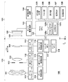
図1は、本発明の実施形態に係る撮像装置の一例としての、レンズ交換式のデジタルカメラ100の機能構成例を示すブロック図である。本実施形態のデジタルカメラ100は、カメラ本体120と、着脱可能なレンズユニット110とを有する。レンズユニット110は点線で示されるマウントMを介して、カメラ本体120に装着することができる。なお、デジタルカメラ100はレンズ交換式でなくてもよい。
● (First embodiment)
(Explanation of Configuration-Lens Unit)
FIG. 1 is a block diagram illustrating an example of a functional configuration of a lens-interchangeable
レンズユニット110は、光学系(第1レンズ群101、絞り102、第2レンズ群103、フォーカスレンズ群(以下、単に「フォーカスレンズ」という)104)および、駆動/制御系を有する。
The
第1レンズ群101はレンズユニット110の先端に配置され、光軸方向OAに移動可能に保持される。絞り102は、撮影時の光量を調節する機能のほか、静止画撮影時には露出時間を制御するメカニカルシャッタとしても機能する。絞り102および第2レンズ群103は一体で光軸方向OAに移動可能であり、第1レンズ群101と連動して移動することによりズーム機能を実現する。フォーカスレンズ104も光軸方向OAに移動可能であり、フォーカスレンズ104の位置により、レンズユニット110が合焦する被写体距離(合焦距離)が定まる。したがって、フォーカスレンズ104の光軸方向OAにおける位置を制御することにより、レンズユニット110の合焦距離を調節することができる。
The
駆動/制御系は、ズームアクチュエータ111、絞りアクチュエータ112、フォーカスアクチュエータ113、ズーム駆動回路114、絞り駆動回路115、フォーカス駆動回路116、レンズMPU117、およびレンズメモリ118を有する。
Drive / control system includes a
ズーム駆動回路114は、ズームアクチュエータ111を用いて第1レンズ群101や第3レンズ群103を光軸方向OAに駆動し、レンズユニット110の光学系の画角を制御する。絞り駆動回路115は、絞りアクチュエータ112を用いて絞り102を駆動し、絞り102の開口径や開閉動作を制御する。フォーカス駆動回路116はフォーカスアクチュエータ113を用いてフォーカスレンズ104を光軸方向OAに駆動し、レンズユニット110の光学系の合焦距離を制御する。また、フォーカス駆動回路116は、フォーカスアクチュエータ113を用いてフォーカスレンズ104の現在位置を検出する。
The
レンズMPU(プロセッサ)117は、レンズユニット110に係る全ての演算、制御を行い、ズーム駆動回路114、絞り駆動回路115、フォーカス駆動回路116を制御する。また、レンズMPU117は、マウントMを通じてカメラMPU125と接続され、コマンドやデータを通信する。例えばレンズMPU117はフォーカスレンズ104の位置を検出し、カメラMPU125からの要求に対してレンズ位置情報を通知する。このレンズ位置情報は、フォーカスレンズ104の光軸方向OAにおける位置、光学系が移動していない状態の射出瞳の光軸方向OAにおける位置および直径、射出瞳の光束を制限するレンズ枠の光軸方向OAにおける位置および直径などの情報を含む。またレンズMPU117は、カメラMPU125からの要求に応じて、ズーム駆動回路114、絞り駆動回路115、フォーカス駆動回路116を制御する。レンズメモリ118は自動焦点検出に必要な光学情報が予め記憶されている。カメラMPU125は例えば内蔵する不揮発性メモリやレンズメモリ118に記憶されているプログラムを実行することで、レンズユニット110の動作を制御する。
The lens MPU (processor) 117 performs all calculations and controls related to the
(構成の説明−カメラ本体)
カメラ本体120は、光学系(光学ローパスフィルタ121および撮像素子122)と、駆動/制御系とを有する。レンズユニット110の光学系(第1レンズ群101、絞り102、第2レンズ群103、フォーカスレンズ104)と、カメラ本体120の光学ローパスフィルタ121とにより、被写体光学像を形成する撮像光学系を構成する。
(Description of configuration-camera body)
The
光学ローパスフィルタ121は、撮影画像に生じる偽色やモアレを軽減する。撮像素子122は例えばCMOSイメージセンサと周辺回路で構成され、一般には行列状に配置された数百万〜数千万の画素を有している。本実施形態の撮像素子122は、瞳分割機能を有し、撮像素子122の出力信号を用いた撮像面位相差AFを実現できる。画像処理回路124は、撮像素子122の出力信号から、位相差AF用の画像データと、表示、記録、およびコントラストAF(以下、TVAFという)用の画像データとを生成する。
The optical low-
駆動/制御系は、センサ駆動回路123、画像処理回路124、カメラMPU125、表示器126、操作スイッチ群127、記録媒体128、位相差AF部129、TVAF部130を有する。
The drive / control system includes a
センサ駆動回路123は、撮像素子122の動作を制御するとともに、撮像素子122の出力する画像信号をA/D変換して画像処理回路124およびカメラMPU125に供給する。画像処理回路124は、センサ駆動回路123から供給される画像データに対し、例えばγ変換、ホワイトバランス調整処理、色補間処理、圧縮符号化処理など、デジタルカメラで行われる一般的な画像処理を行う。画像処理回路124は表示、記録、およびTVAF用の画像データと、位相差AF用の画像データとを生成する。
The
カメラMPU(プロセッサ)125は、カメラ本体120に係る全ての演算、制御を行い、センサ駆動回路123、画像処理回路124、表示器126、操作スイッチ群127、記録媒体128、位相差AF部129、TVAF部130を制御する。カメラMPU125はマウントMの信号線を介してレンズMPU117と接続され、レンズMPU117とコマンドやデータを通信する。カメラMPU125はレンズMPU117に対し、レンズユニット110の光学情報やフォーカスレンズ104の位置の取得を要求する。また、カメラMPU125はレンズMPU117に対し、絞り102、フォーカスレンズ104、変倍レンズ(第1レンズ群101および第3レンズ群103)の駆動を要求する。カメラMPU125は、カメラ本体120の動作を制御するプログラムを格納したROM125a、プログラムをロードしたり変数を記憶したりするために用いるRAM125b、設定値やGUIデータなどを記憶するEEPROM125cを有している。
A camera MPU (processor) 125 performs all calculations and controls related to the
表示器126はLCDなどから構成され、撮影モードに関する情報、撮影前のプレビュー画像と撮影後の確認用画像、メニュー画面、焦点検出時の合焦状態表示画像(合焦枠)、検出された被写体を示す画像(顔枠など)、設定値などを表示する。操作スイッチ(SW)群127は、電源スイッチ、レリーズスイッチ、ズーム操作スイッチ、撮影モード選択スイッチ、メニューボタン、方向キー、実行ボタンなどのスイッチ、ボタンなどの入力デバイス群である。なお、表示器126がタッチパネルディスプレイの場合、タッチパネルも操作スイッチに含まれる。記録媒体128は、例えば着脱可能な半導体メモリカードや内蔵不揮発性メモリであり、撮影によって得られた静止画、動画、音声などのデータを格納する。
The
位相差AF部129は、画像処理回路124により得られる位相差AF用の画像データを用い、位相差検出方式の焦点検出を行う。より具体的には、画像処理回路124が、レンズユニット110の光学系の射出瞳内の一対の瞳領域の一方を通過する光束で形成される像と、他方を通過する光束で形成される像とのデータを位相差AF用の画像データとして生成する。そして、位相差AF部129は位相差AF用の画像データを構成する一対の像のデータの位相差(ずれ量)に基づいて焦点ずれ量を検出する。このように、本実施形態の位相差AF部129は、専用のAFセンサを用いず、撮像素子122の出力に基づく位相差AF(撮像面位相差AF)を行う。位相差AF部129の動作については後で詳細に説明する。
The phase
TVAF部130は、画像処理回路124が生成するTVAF用の画像データ、より具体的にはAF評価値(画像データのコントラスト情報)に基づいてコントラスト検出方式の焦点検出(TVAF)を行う。TVAFは、フォーカスレンズ104の異なる位置で撮影された画像から、AF評価値が最大となるフォーカスレンズ104の位置を合焦位置として検出する。
このように、本実施形態のデジタルカメラ100は、位相差AFとTVAFの両方を実行可能であり、状況に応じて選択的に使用したり、組み合わせて使用したりすることができる。
The
As described above, the
(構成の説明−撮像素子)
図2は、本実施形態の撮像素子122に行列上に配置された画素のうち、撮像画素の4列×4行分を模式的に示している。本実施形態において撮像素子122は、撮像画像の1画素分の信号を得るための撮像画素の各々の光電変換領域が行方向に2等分され、光電変換領域ごとの出力を取得することができる。光電変換領域ごとの出力を用いて撮像面位相差AF用の画像データを生成可能であるため、個々の光電変換領域は焦点検出画素とみなすことができる。したがって、図2は、焦点検出画素の8列×4行分ともいえる。
(Explanation of Configuration-Image Sensor)
FIG. 2 schematically illustrates 4 columns × 4 rows of imaging pixels among the pixels arranged in a matrix on the
撮像素子122には、撮像画素の2行×2列を繰り返し単位200とした原色ベイヤー配列のカラーフィルタが設けられている。繰り返し単位200は、G(緑)のカラーフィルタが設けられた2つの撮像画素200Gと、R(赤)のカラーフィルタが設けられた1つの撮像画素200Rと、B(青)のカラーフィルタが設けられた1つの撮像画素200Bとから構成される。本明細書では、設けられたカラーフィルタの色を撮像画素の色として記載する場合がある。また、単に画素と呼ぶ場合には撮像画素を指すものとする。例えば、画素200Gは緑画素、200Rは赤画素、200Bは青画素である。また、図2の右上の画素に代表的に示すように、各撮像画素は、横2×縦1に等分割された光電変換部を有しており、左半分の光電変換部が第1焦点検出画素201、右半分の光電変換部が第2焦点検出画素202として利用可能である。撮像画素として利用する場合には、2つの光電変換部で得られた信号を加算した信号を撮像信号として用いる。
The
図2に示した4×4の撮像画素(8×4焦点検出画素)の配列を撮像素子122の撮像面に多数配置することにより、撮像画像を取得しつつ、画面の様々な位置を焦点検出領域として用いた撮像面位相差検出方式の焦点検出を行うことができる。本実施形態では、撮像画素のピッチ(周期)Pが縦横とも4μmで、画素数Nは、横5575×縦3725=約2075万画素であるものとする。また、焦点検出画素の縦方向のピッチPは撮像画素と同じであるが、横方向のピッチPAFは2μmであり、従って焦点検出画素数NAFが横11150×縦3725=約4150万画素であるものとする。
By arranging a large number of 4 × 4 image pickup pixels (8 × 4 focus detection pixels) shown in FIG. 2 on the image pickup surface of the
図2に示した1つの撮像画素(ここでは200Gとする)を、撮像素子の受光面側(+z側)から見た平面図を図3(a)に示し、図3(a)のa−a断面を−y側から見た断面図を図3(b)に示す。 FIG. 3A is a plan view of one imaging pixel (200 G in this example) shown in FIG. 2 viewed from the light receiving surface side (+ z side) of the imaging device. FIG. 3B is a cross-sectional view of the cross section a viewed from the −y side.
図3に示すように、本実施形態の画素200Gでは、各画素の受光側に入射光を集光するためのマイクロレンズ305が形成され、x方向にNH分割(2分割)、y方向にNV分割(1分割)された光電変換部301と光電変換部302が形成される。光電変換部301と光電変換部302が、それぞれ、第1焦点検出画素201と第2焦点検出画素202に対応する。
As shown in FIG. 3, in the
光電変換部301と光電変換部302は、p型層とn型層の間にイントリンシック層を挟んだpin構造フォトダイオードとしても良いし、必要に応じて、イントリンシック層を省略し、pn接合フォトダイオードとしてもよい。
The
各画素には、マイクロレンズ305と、光電変換部301および光電変換部302との間に、カラーフィルタ306が形成される。また、必要に応じて、第1焦点検出画素201と第2焦点検出画素202とでカラーフィルタの分光透過率を変えても良いし、カラーフィルタを省略してもよい。
In each pixel, a
図3に示した画素200Gに入射した光は、マイクロレンズ305により集光され、カラーフィルタ306で分光されたのち、光電変換部301と光電変換部302で受光される。
Light that has entered the
光電変換部301と光電変換部302では、受光量に応じて電子とホールが対生成し、空乏層で分離された後、負電荷の電子はn型層に蓄積され、ホールは定電圧源(不図示)に接続されたp型層300を通じて撮像素子122の外部へ排出される。
In the
光電変換部301と光電変換部302のn型層に蓄積された電子は、転送ゲートを介して、静電容量部(FD)に転送され、電圧信号に変換される。
The electrons accumulated in the n-type layers of the
図3に示した本実施形態の画素構造と瞳分割との対応関係を示した概略説明図を図4に示す。図4では、射出瞳面の座標軸と対応を取るために、断面図のx軸とy軸を図3に対して反転させている。 FIG. 4 is a schematic explanatory diagram showing the correspondence between the pixel structure and the pupil division of the present embodiment shown in FIG. In FIG. 4, the x-axis and the y-axis of the sectional view are inverted with respect to FIG. 3 in order to correspond to the coordinate axes of the exit pupil plane.
図4で、第1焦点検出画素201の第1瞳部分領域501は、重心が−x方向に偏心している光電変換部301の受光面と、マイクロレンズ305によって、概ね共役関係になっており、第1焦点検出画素201で受光可能な瞳領域を表している。第1焦点検出画素201の第1瞳部分領域501は、瞳面上で+X側に重心が偏心している。
In FIG. 4, the first pupil
図4で、第2焦点検出画素202の第2瞳部分領域502は、重心が+x方向に偏心している光電変換部302の受光面と、マイクロレンズ305によって、概ね共役関係になっており、第2焦点検出画素202で受光可能な瞳領域を表している。第2焦点検出画素202の第2瞳部分領域502は、瞳面上で−X側に重心が偏心している。
In FIG. 4, the second pupil
また、図4で、瞳領域500は、光電変換部301と光電変換部302(第1焦点検出画素201と第2焦点検出画素202)を合わせた、画素200G全体で受光可能な瞳領域である。
In FIG. 4, the
本実施形態の撮像素子と瞳分割との対応関係を示した概略図を図5(a)に示す。第1瞳部分領域501と第2瞳部分領域502の異なる瞳部分領域を通過した光束は、撮像素子の各(撮像)画素に、撮像面800からそれぞれ異なる角度で入射し、2×1分割された光電変換部301および302で受光される。なお、本実施形態は、瞳領域が水平方向に2つに瞳分割されているが、必要に応じて、垂直方向に瞳分割を行ってもよい。
FIG. 5A is a schematic diagram showing the correspondence between the image sensor and pupil division according to the present embodiment. Light beams that have passed through different pupil partial areas of the first pupil
撮像素子122には、結像光学系の第1瞳部分領域501を通過する光束を受光する第1焦点検出画素201と、第1瞳部分領域と異なる結像光学系の第2瞳部分領域502を通過する光束を受光する第2焦点検出画素202を有する撮像画素が配列されている。従って、撮像画素は、結像光学系の第1瞳部分領域501と第2瞳部分領域502を合わせた瞳領域500を通過する光束を受光する。
The
なお、撮像素子122が有する全ての画素が複数の光電変換部を有するのではなく、撮像画素、第1焦点検出画素、第2焦点検出画素を個別の画素構成としてもよい。あるいは、光電変換部を1つ有する撮像画素と、光電変換部を2つ有する(撮像画素としても使用可能な)焦点検出画素とが配置されても良い。
Note that not all the pixels included in the
本実施形態において画像処理回路124は、図2に示したカラーフィルタの繰り返し単位ごとに4つの第1焦点検出画素201の出力を加算して得られる信号を複数連結して1つの位相差AF用の画像データ(AF用像信号)を生成する(以下、A像という)。また、画像処理回路124は、カラーフィルタの繰り返し単位ごとに4つの第2焦点検出画素202の出力を加算して得られる信号を複数連結してもう1つのAF用像信号(以下、B像という)を生成する。カラーフィルタの繰り返し単位内に存在する同種の焦点検出画素の出力を加算することで、R,G,Bそれぞれの色成分を反映した信号が得られるため、分光感度の偏りが少ない輝度信号として扱うことができる。なお、撮像画像を得る場合には、画素単位で第1焦点検出画素201の出力と第2焦点検出画素202の出力とを加算した信号を取得する。
In this embodiment, the
●(デフォーカス量と像ずれ量の関係)
以下、本実施形態の画像処理回路124で生成される1対の位相差AF用の画像データ(A像およびB像)の像ずれ量と、光学系のデフォーカス量との関係について説明する。 図5(b)に、デフォーカス量と、第1焦点検出信号(A像)−第2焦点検出信号(B像)間の像ずれ量との概略関係図を示す。撮像面800に撮像素子122が配置され、図4、図5(a)を参照して説明したように、撮影光学系の射出瞳が、第1瞳部分領域501と第2瞳部分領域502に2分割される。
● (Relation between defocus amount and image shift amount)
Hereinafter, the relationship between the image shift amount of the pair of phase difference AF image data (A image and B image) generated by the
デフォーカス量dの大きさ|d|は、被写体の結像位置から撮像面800までの距離である。また、デフォーカス量dが負(d<0)の場合は、被写体の結像位置が撮像面800より被写体側にある前ピン状態、正(d>0)の場合は、被写体の結像位置が撮像面800より被写体の反対側にある後ピン状態を意味する。そして、被写体の結像位置が撮像面800にある合焦状態で、デフォーカス量dの大きさは0となる。図5(a)で、被写体801は合焦状態(d=0)にあり、被写体802は前ピン状態(d<0)の例を示している。前ピン状態(d<0)と後ピン状態(d>0)を合わせて、デフォーカス状態(|d|>0)と呼ぶ。
The magnitude | d | of the defocus amount d is a distance from the imaging position of the subject to the
前ピン状態(d<0)では、被写体802からの光束のうち、第1瞳部分領域501(第2瞳部分領域502)を通過した光束は、撮像面800より被写体側の位置で一度集光する。そして、その後、光束の重心位置G1(G2)を中心として幅Γ1(Γ2)に広がり、撮像面800でボケた像となる。ボケた像は、それを受光する複数の画素のそれぞれで第1焦点検出画素201(第2焦点検出画素202)により電気信号に変換される。そして、上述したように、位相差AF部が、第1焦点検出画素201の信号から第1焦点検出信号(A像)を、第2焦点検出画素202の信号から第2焦点検出信号(B像)を生成する。よって、A像(B像)は、撮像面800上の重心位置G1(G2)に、被写体802が幅Γ1(Γ2)にボケた被写体像として記録される。
In the front focus state (d <0), of the light beams from the
被写体像のボケ幅Γ1(Γ2)は、デフォーカス量dの大きさ|d|の増加に概ね比例して増加する。同様に、第1焦点検出信号と第2焦点検出信号間の被写体像の像ずれ量p(=光束の重心位置の差G1−G2)の大きさ|p|も、デフォーカス量dの大きさ|d|の増加に概ね比例して増加していく。後ピン状態(d>0)の場合、A像とB像との像ずれ方向が前ピン状態と反対となることをのぞき、デフォーカス量の大きさ|d|と被写体像のボケ幅、像ずれ量pとの関係は同様である。
したがって、デフォーカス量の大きさの増加に伴い、A像とB像との像ずれ量の大きさが増加する。
The blur width Γ1 (Γ2) of the subject image increases substantially in proportion to the increase of the magnitude | d | of the defocus amount d. Similarly, the magnitude | p | of the image shift amount p of the subject image between the first focus detection signal and the second focus detection signal (= difference G1-G2 between the centers of gravity of the light beams) is also the magnitude of the defocus amount d. | D | generally increases in proportion to the increase. In the back focus state (d> 0), the magnitude of the defocus amount | d |, the blur width of the subject image, and the image, except that the image shift directions of the A image and the B image are opposite to the front focus state. The relationship with the shift amount p is the same.
Therefore, as the magnitude of the defocus amount increases, the magnitude of the image shift amount between the A image and the B image increases.
●(焦点検出)
[焦点検出領域]
まず、第1焦点検出信号と第2焦点検出信号とを生成するために用いる、撮像素子122の画素領域である、焦点検出領域について説明する。図6は、撮像素子122の有効画素領域1000に設定された焦点検出領域の例と、焦点検出時に表示器126に表示される焦点検出領域の指標とを重ねて示したものである。本実施形態では行方向に3つ、列方向に3つの、計9個の焦点検出領域が設定されているものとするが、これは単なる一例であり、より多くの、もしくはより少ない数の焦点検出領域が設定されてもよい。また、焦点検出領域は等間隔で設定されなくてもよい。さらに、撮像素子122のように有効画素領域1000のどの画素も第1焦点検出画素および第2焦点検出画素を有する場合、焦点検出領域の位置やサイズを動的に設定してもよい。例えば、ユーザが指定した位置を中心に、所定の範囲を焦点検出領域として設定してもよい。
● (Focus detection)
[Focus detection area]
First, a focus detection area, which is a pixel area of the
図6において、行方向にn番目、列方向にm番目の焦点検出領域をA(n,m)と表し、A(n,m)の焦点検出領域を表す矩形枠状の指標をI(n,m)と表している。焦点検出領域内の第1焦点検出画素201と第2焦点検出画素202から得られる信号により、その焦点検出領域におけるデフォーカス量の検出に用いるA像およびB像が生成される。また、指標I(n,m)は通常、ライブビュー画像に重畳表示される。
In FIG. 6, an n-th focus detection area in the row direction and an m-th focus detection area in the column direction are denoted by A (n, m), and a rectangular frame-like index representing the focus detection area of A (n, m) is denoted by I (n , M). Based on signals obtained from the first
[焦点検出]
次に、カメラMPU125が主体となって実現する、デジタルカメラ100の焦点検出動作について、図7に示すフローチャートを用いて説明する。なお、この処理は、撮影スタンバイ時のようなライブビュー表示時(表示用動画撮影時)や、動画記録時(記録用動画撮影時)において実施される。
[Focus detection]
Next, a focus detection operation of the
S501でカメラMPU125は、操作スイッチ群127などを通じて焦点検出動作の開始指示が入力されたか調べ、入力されていれば処理をS502へ進め、入力されていなければ待機する。なお、カメラMPU125は、焦点検出開始指示の入力に限らず、ライブビュー表示や動画記録の開始をトリガとして処理をS502に進めてもよい。
In step S501, the
S502でカメラMPU125は、レンズユニット110のF値、レンズ枠情報やフォーカスレンズ位置、ピント補正量、最大デフォーカス量などの各種レンズ情報を、マウントMを介してレンズMPU117から取得する。
In step S502, the
S503でカメラMPU125は、逐次読み出されているフレーム画像データの、焦点検出領域内の画素データから、第1の焦点検出信号(A像)と第2の焦点検出信号(B像)を生成するように画像処理回路124に指示する。画像処理回路124は指示に従ってA像とB像を生成し、カメラMPU125に出力する。後述するように、本実施形態において画像処理回路124はA像、B像を複数対生成する。
In step S <b> 503, the
S504でカメラMPU125は、画像処理回路124が生成した複数対のA像、B像を位相差AF部129に供給する。位相差AF部129は、A像とB像の各対に対して公知の相関演算などを適用して像のずれ量を算出する。また、位相差AF部129は、検出されたずれ量の信頼性なども判定し、得られた複数のずれ量の1つをデフォーカス量に変換する。この処理の詳細は、後述する。位相差AF部129は、選択したデフォーカス量をカメラMPU125に出力する。
In step S504, the
S505でカメラMPU125は、S504で位相差AF部129から得られたデフォーカス量に基づき、レンズユニット110のフォーカスレンズ104の駆動方向および駆動量を算出する。なお、位相差AF部129が焦点検出不能と判定した場合、カメラMPU125はフォーカスレンズ104を停止させる。あるいはカメラMPU125は、フォーカスレンズ104の駆動モードをサーチ駆動モードに移行させるとともに、所定量のレンズ駆動を行うためのレンズ駆動量を算出する。たとえばカメラMPU125は、事前に決めた、被写体が存在する可能性が高い方向、例えば至近側に、所定量フォーカスレンズ104を駆動することを決定する。
In S505, the
S506でカメラMPU125は、マウントMおよびレンズMPU117を介して、フォーカスレンズ104の駆動方向および駆動量の情報をフォーカス駆動回路116に送信する。フォーカス駆動回路116は、受信した駆動方向と駆動量の情報に基づいて、フォーカスレンズ104を駆動する。これにより、レンズユニット110の焦点調節が行われる。なお、図7の動作は、動画像データの次フレーム以降に対しても同様に実施されてよい。
In step S506, the
次に、図7のS503で画像処理回路124が行う信号生成処理について、図8に示すフローチャートを用いて説明する。
まず、S5031で、画像処理回路124は、焦点検出領域内の画素が有する第1焦点検出画素201と第2焦点検出画素202の出力を用いて、1対の焦点検出信号を生成する。上述したように、画像処理回路124は、第1焦点検出画素201(第2焦点検出画素202)の出力を、まずカラーフィルタの繰り返し単位ごとに加算してから、焦点検出方向に連結して焦点検出用の像信号であるA像(B像)を生成する。
Next, the signal generation processing performed by the
First, in step S5031, the
次にS5032で画像処理回路124は、S5031で生成した1対の像信号を補正する。この補正には例えば、光学系の周辺光量低下(ビネッティング)に起因する像信号間のレベル差の補正や、画素感度のばらつきに起因する固定パターンノイズの補正が含まれる。画像処理回路124は、補正後の像信号を、例えばカメラMPU125のRAM125bに一時的に保存する。
Next, in step S5032, the
S5033で、画像処理回路124は、補正後の像信号をRAM125bから読み出し、第1の信号を生成する。第1の信号は、補正後のA像、B像それぞれについて、データ量を削減した1対の像信号であり、画像処理回路124は例えばデータを間引きしたり、隣接する複数のデータを代表値で置換したりすることで生成する。
In step S5033, the
例えば、データ量を1/3に圧縮した第1の信号を、連続する3つのデータを代表値(ここでは平均値とする)で置換することにより生成するものとする。この場合、補正後のA像およびB像をそれぞれA(k)、B(k)(1≦k≦Pの整数)で表すと、第1の信号A2(m)、B2(m)(1≦m≦Qの整数)は、以下の式(1),(2)で表される。
A2(m)=(A(m)+A(m+1)+A(m+2))/3 (1)
B2(m)=(B(m)+B(m+1)+B(m+2))/3 (2)
これにより、第1の信号A2(m)、B2(m)を形成するデータの数は、おおよそP/3個に圧縮(削減)される。画像処理回路124は、第1の信号をカメラMPU125の例えばRAM125bに保存する。
For example, it is assumed that a first signal whose data amount is compressed to 1/3 is generated by replacing three consecutive data with a representative value (here, an average value). In this case, when the A image and the B image after the correction are represented by A (k) and B (k) (1 ≦ k ≦ P, respectively), the first signals A2 (m) and B2 (m) (1 ≦ m ≦ Q) is represented by the following equations (1) and (2).
A2 (m) = (A (m) + A (m + 1) + A (m + 2)) / 3 (1)
B2 (m) = (B (m) + B (m + 1) + B (m + 2)) / 3 (2)
Thereby, the number of data forming the first signals A2 (m) and B2 (m) is compressed (reduced) to approximately P / 3. The
S5034で、で、画像処理回路124は、補正後の像信号を再びRAM125bから読み出し、第2の信号を生成する。第2の信号は、補正後のA像、B像それぞれについて、第1の信号よりデータ量の削減が少ない1対の像信号である。例えば、データ量の削減を行わない場合、画像処理回路124は読み出した補正後のA像、B像をそのまま第2の信号とすることができる。補正後のA像およびB像をそれぞれA(k)、B(k)(1≦k≦Pの整数)で表すと、第2の信号A3(n)、B3(n)(1≦n≦Pの整数)は、以下の式(3),(4)で表される。
A3(n)=A(n) (3)
B3(n)=B(n) (4)
画像処理回路124は、第2の信号をカメラMPU125の例えばRAM125bに保存する。
In step S5034, the
A3 (n) = A (n) (3)
B3 (n) = B (n) (4)
The
S5033、S5034で生成する第1の信号と第2の信号のデータ圧縮率(圧縮後のデータ量/圧縮前のデータ量(%))は、上述した例に限らない。例えば、記録画像のデータ圧縮率が高い場合には、第1の信号のデータ量を1/6に圧縮し、第2の信号のデータ量を1/2に圧縮するようにしてもよい。
S5034で第2の信号の生成を終えると、画像処理回路124は焦点検出用信号生成処理を終了する。
The data compression ratio (data amount after compression / data amount before compression (%)) of the first signal and the second signal generated in S5033 and S5034 is not limited to the above example. For example, when the data compression ratio of the recorded image is high, the data amount of the first signal may be compressed to 6 and the data amount of the second signal may be compressed to 1 /.
When the generation of the second signal ends in step S5034, the
次に、図7のS504で位相差AF部129が行うデフォーカス量の検出処理について、図9に示すフローチャートを用いてさらに説明する。
S5041で位相差AF部129は、カメラMPU125から供給される第1の信号と第2の信号のうち、第1の信号のA像とB像に対する相関演算(第1の相関演算)を行う。位相差AF部129は、相関演算を行う際、視野内データ数とシフトデータ数を設定する。視野内データとは、相関演算を行う際の窓に相当し、焦点検出を行う領域の広さを決定する。視野内データ数を大きくすると、相関演算結果の信頼性を高めることができる一方、距離の異なる被写体が焦点検出領域内に存在する場合に遠近競合が発生しやすくなる。遠近競合とは、距離の異なる被写体に係る像信号の相関演算を行った場合に、デフォーカス量が検出できなかったり、デフォーカス量を検出する被写体を誤ったりする現象である。
Next, the process of detecting the defocus amount performed by the phase
In step S5041, the phase
遠近競合の発生を抑制しつつ、精度の良いデフォーカス量を検出するには、被写体の大きさや光学系の焦点距離(画角)などの情報をもとに、A像とB像に、相関演算に用いる適切な範囲(区間)を設定する必要がある。この範囲の大きさを定めるのが視野内データ数であり、例えば位相差AF部129は、予め定められたパラメータの種類と値との組み合わせごとに視野内データ数が登録されたテーブルを参照するなどして設定することができる。また、シフトデータ数は、A像とB像の相対位置(位相差)を変化させながら相関量を算出する際の最大ずらし量に相当する。相関量算出時のA像とB像の最大ずらし量を大きくすると、ボケの大きな被写体に対するデフォーカス量の検出が可能になる反面、相関量の算出に要する演算量が増加し、焦点検出に要する時間が長くなる。
To detect an accurate defocus amount while suppressing the occurrence of perspective conflict, the A image and the B image are correlated based on information such as the size of the subject and the focal length (angle of view) of the optical system. It is necessary to set an appropriate range (section) used for the calculation. The size of this range is determined by the number of data in the visual field. For example, the phase
本実施形態において、第1の信号は、第2の信号よりも圧縮率が高いため、圧縮前のA像とB像における同一ずらし量に対応するシフトデータ数は第2の信号よりも少なくなる。そのため、第2の信号に対する相関演算よりも、おおきなずらし量に対応するシフトデータ数を設定して相関演算を行い、より広いデフォーカス範囲の焦点検出を行う。 In the present embodiment, since the first signal has a higher compression ratio than the second signal, the number of shift data corresponding to the same shift amount between the A image and the B image before compression is smaller than that of the second signal. . Therefore, the correlation calculation is performed by setting the number of shift data corresponding to the large shift amount, and the focus detection in a wider defocus range is performed than the correlation calculation for the second signal.
第1の相関演算に用いる相関量COR1(h)は、例えば下記の式(5)で算出することができる。

なお、本実施形態では、相関量COR1の差分値の符号が変化するシフト量を、相関量COR1(h)が最小となるシフト量h(サブピクセル単位)として算出する。
まず、位相差AF部129は、相関量の差分値DCOR1を以下の式(6)に従って算出する。
DCOR1(h)=COR1(h)−COR1(h−1) (6)
そして、位相差AF部129は、相関量の差分値DCOR1を用いて、差分量の符号が変化するシフト量dh1を求める。差分量の符号が変化する直前のhの値をh1、符号が変化したhの値をh2(h2=h1+1)とすると、位相差AF部129はシフト量dh1を、以下の式(7)に従って算出する。
dh1=h1+|DCOR1(h1)|/|DCOR1(h1)−DCOR1(h2)|
(7)
以上のようにして位相差AF部129は、第1の信号のA像とB像の相関が最大となるシフト量dh1をサブピクセル単位で算出し、S5041の処理を終える。なお、2つの1次元像信号のずれ量(位相差)を算出する方法は、ここで説明したものに限らず、公知の任意の方法を用いることができる。
In the present embodiment, the shift amount at which the sign of the difference value of the correlation amount COR1 changes is calculated as the shift amount h (sub-pixel unit) at which the correlation amount COR1 (h) is minimized.
First, the phase
DCOR1 (h) = COR1 (h) -COR1 (h-1) (6)
Then, the phase
dh1 = h1 + | DCOR1 (h1) | / | DCOR1 (h1) −DCOR1 (h2) |
(7)
As described above, the phase
次に、S5042で、相関演算手段としての位相差AF部129は、第2の信号のA像(A3)とB像(B3)に対する相関演算(第2の相関演算)を行う。ここでも位相差AF部129は、視野内データ数とシフトデータ数を設定する。視野内データ数は、上述のとおり被写体の遠近競合とデフォーカス検出精度とを考慮して設定する。本実施形態で位相差AF部129は、圧縮前のA像およびB像において、第1の相関演算時に設定した視野内データ数に対応する範囲と概ね同一の範囲に対応する視野内データ数を設定する。これは、第1の信号と第2の信号とで相関演算に用いる信号の起点が共通の場合、圧縮率の差を考慮した視野内データ数を設定することにより実現できる。本実施形態では、第1の信号は第2の信号の1/3に圧縮されているため、第2の相関演算における視野内データ数は、第1の相関演算における視野内データ数の3倍とすればよい。
Next, in S5042, the phase
このように、第1の信号に対する相関演算と第2の信号に対する相関演算において、圧縮前の像信号において概ね同一領域を対象とするように視野内データ数を設定することにより、2つの相関演算結果を切り替えて使用することが可能になる。2つの相関演算が、圧縮前の像信号において異なる範囲を対象としていると、それぞれの相関演算結果が異なる被写体を対象としている可能性があり、2つの相関演算結果を切り替えてフォーカスレンズを駆動した場合、合焦する被写体が変化してしまう場合がある。本実施形態では、第1の相関演算と第2の相関演算は、検出可能なデフォーカス量の範囲は異なるが、同じ像信号の範囲に基づいて相関演算を行っているため、合焦度合いに応じて両者を切り替えて用いることができる。 As described above, in the correlation calculation for the first signal and the correlation calculation for the second signal, by setting the number of data in the field of view so as to cover substantially the same region in the image signal before compression, two correlation calculations are performed. The result can be switched and used. If the two correlation calculations target different ranges in the image signal before compression, the correlation calculation results may target different subjects, and the focus lens was driven by switching the two correlation calculation results. In this case, the subject to be focused may change. In the present embodiment, the first correlation calculation and the second correlation calculation have different defocus amount ranges, but perform the correlation calculation based on the same image signal range. The two can be switched and used accordingly.
本実施形態において、第2の信号は、第1の信号に対して圧縮率が低いため、第1の信号よりも高周波成分を多く有している。そのため、光学系の収差の影響やF値によらず、単位デフォーカス量あたりの像ずれ量を比較的大きく確保でき、第1の信号を用いる場合より精度の高いデフォーカス量を検出できる。一方、第2の信号は第1の信号よりもデータ数が多いため、シフト量ごとの相関量を得るための演算量が第1の信号よりも多くなる。さらに、同じデフォーカス量の範囲に対応する相関量を得るためのシフト回数が第1の信号よりも多いため、第1の相関演算と同じシフトデータ数を設定すると演算量がさらに多くなる。したがって、第2の相関演算では、第1の相関演算よりも、シフトデータ数を小さく設定し、より狭い範囲でデフォーカス量を検出する。 In the present embodiment, since the second signal has a lower compression ratio than the first signal, it has more high frequency components than the first signal. Therefore, a relatively large image shift amount per unit defocus amount can be ensured irrespective of the influence of the aberration of the optical system or the F value, and the defocus amount can be detected with higher accuracy than when the first signal is used. On the other hand, since the second signal has a larger number of data than the first signal, the amount of calculation for obtaining the correlation amount for each shift amount is larger than that of the first signal. Further, since the number of shifts for obtaining the correlation amount corresponding to the same range of the defocus amount is larger than that of the first signal, setting the same number of shift data as in the first correlation calculation further increases the calculation amount. Therefore, in the second correlation calculation, the number of shift data is set smaller than in the first correlation calculation, and the defocus amount is detected in a narrower range.
位相差AF部129は、第2の相関演算に用いる相関量COR2(g)、相関量の差分値DCOR2(g)を、視野内データ数Wとシフトデータ数hmaxの値が異なることをのぞき、相関量COR1(h)、相関量の差分値DCOR1(h)と同様に算出する。また、位相差AF部129は、第2の信号のA像とB像の相関が最大となるシフト量dh2も、dh1と同様にしてサブピクセル単位で算出する。
The phase
次に、S5043で位相差AF部129は、第2の相関演算結果の信頼性を評価する。信頼性の評価は、例えば、COR2(g)の極小値の大きさや、シフト量dh2近傍のDCOR2(g)の大きさに基づいて行うことができる。COR2(g)の極小値は、小さいほどA像信号とB像信号の一致度が高いことを示すため、小さいほど相関演算結果の信頼性は高いと評価できる。また、DCOR2(g)の大きさが大きいほど、シフト量に対する相関量の変化が大きいことを示すため、サブピクセル単位のシフト量dh2の精度が高く、やはり相関演算結果の信頼性は高いと評価できる。位相差AF部129は、これら値の1つ以上を用いて、相関演算結果の信頼性を評価する。なお、評価に複数の値を用いる場合には、例えば個々の値が一定の信頼性を有しつつ、かつ少なくとも一方が高い信頼性に該当する場合に、相関演算結果の信頼性がある(高い)と評価することができる。なお、この評価基準は一例であり、他の評価基準も採用しうる。
Next, in step S5043, the phase
S5043で、第2の相関演算結果に信頼性があると判定されると、位相差AF部129は処理をS5045に進め、第2の相関演算で得られたシフト量(ずれ量)に対して所定の敏感度を適用してデフォーカス量を算出する。そして位相差AF部129は、算出したデフォーカス量をカメラMPU125に出力して処理を終了する。上述の通り、第2の信号を用いる第2の相関演算は、第1の信号を用いる第1の相関演算よりも検出可能なデフォーカス範囲は狭いが、検出精度は高い。したがって、第2の相関演算結果が信頼できる場合には、第1の相関演算結果よりも第2の相関演算結果を優先して用いてデフォーカス量を検出する。
If it is determined in step S5043 that the result of the second correlation operation is reliable, the phase
一方、S5043で第2の相関演算結果に信頼性がない(低い)と判定されると、位相差AF部129は処理をS5044に進め、第1の相関演算結果について信頼性を評価する。信頼性の評価は、第2の相関演算結果と同様に行うことができるが、評価基準は第2の相関演算結果に用いるものより緩くしてもよい。第1の相関演算結果に信頼性がある(高い)と判定されると、位相差AF部129は処理をS5046に進め、第1の相関演算で得られたシフト量(ずれ量)に対して所定の敏感度を適用してデフォーカス量を算出する。そして位相差AF部129は、算出したデフォーカス量をカメラMPU125に出力して処理を終了する。第2の相関演算結果に信頼性がないと判定されているため、合焦近傍のデフォーカス状態ではない(デフォーカス量が大きい)と推定される。したがって、第2の相関演算よりも、検出可能なデフォーカス範囲が広い第1の相関演算の結果を用いてデフォーカス量を検出する。
On the other hand, if it is determined in step S5043 that the second correlation calculation result is unreliable (low), the phase
また、S5044で、第1の相関演算結果についても信頼性がない(低い)と判定された場合、位相差AF部129は処理をS5047に進め、焦点検出不能と判定し、カメラMPU125に通知して処理を終了する。
If the first correlation calculation result is determined to be unreliable (low) in S5044, the phase
このように本実施形態では、第1の焦点検出信号と第2の焦点検出信号から、圧縮率の異なる複数対の信号を生成し、個々の信号対のずれ量を検出する。そして、信頼性が高いと判定されるずれ量のうち、圧縮率の低い方の(または最も低い)信号対のずれ量に基づいてデフォーカス量を算出するようにした。このような構成の利点について説明する。 As described above, in the present embodiment, a plurality of pairs of signals having different compression ratios are generated from the first focus detection signal and the second focus detection signal, and a shift amount of each signal pair is detected. The defocus amount is calculated based on the shift amount of the signal pair having the lower (or lowest) compression ratio among the shift amounts determined to be high in reliability. The advantages of such a configuration will be described.
図10は、本実施形態における第1の相関演算と第2の相関演算で用いられる視野内データ数Wとシフトデータ数hmaxの組み合わせを示す図である。第1の相関演算の対象である第1の信号は、焦点検出信号(A像、B像)を位相差検出方向に1/3に圧縮した信号のため、視野内データ数W1は第2の相関演算の視野内データ数W2の1/3である。しかしながら、視野内データ数W1とW2が対応する焦点検出信号の区間の大きさは、概ね同一となるように構成されている。また、第1の相関演算においては、第2の相関演算よりも大きなデフォーカス量(ずれ量)の検出に対応するようにシフトデータ量S1を設定する。そのため、シフトデータ数S1の視野内データ数W1に対する割合S1/W1を、第2の相関演算のシフトデータ数S2の視野内データ数W2に対する割合S2/W2より大きくなるように設定する。 FIG. 10 is a diagram showing a combination of the number W of data within the visual field and the number hmax of shift data used in the first correlation operation and the second correlation operation in the present embodiment. Since the first signal to be subjected to the first correlation operation is a signal obtained by compressing the focus detection signals (A image and B image) to 1/3 in the phase difference detection direction, the number of data W1 in the visual field is equal to the second signal. This is 3 of the number of data W2 in the visual field of the correlation operation. However, the size of the section of the focus detection signal corresponding to the in-field data numbers W1 and W2 is configured to be substantially the same. In the first correlation calculation, the shift data amount S1 is set so as to correspond to detection of a larger defocus amount (deviation amount) than in the second correlation calculation. Therefore, the ratio S1 / W1 of the number of shift data S1 to the number of data W1 in the visual field is set to be larger than the ratio S2 / W2 of the number of shift data S2 of the second correlation operation to the number of data in the visual field W2.
図10に示す圧縮率の場合、第2の相関演算において第1の相関演算と同様の範囲のデフォーカス量を検出可能にするには、シフトデータ数をS1の3倍に設定する必要がある。これにより広いデフォーカス検出範囲と精度の高い焦点検出とを両立できるが、シフト演算回数が、±3×S1回と多くなってしまう。本実施形態では、検出するデフォーカス範囲と検出精度の確保を複数種の相関演算によって実現することにより、より少ないシフト回数(S1+S2)で、演算量の低減と演算精度の確保とを両立している。 In the case of the compression ratio shown in FIG. 10, the number of shift data needs to be set to three times S1 so that the defocus amount in the same range as in the first correlation operation can be detected in the second correlation operation. . This makes it possible to achieve both a wide defocus detection range and highly accurate focus detection, but the number of shift calculations increases to ± 3 × S1. In the present embodiment, by ensuring a defocus range to be detected and the detection accuracy by a plurality of types of correlation calculations, it is possible to reduce the amount of calculation and ensure the calculation accuracy with a smaller number of shifts (S1 + S2). I have.
また、第1の相関演算と第2の相関演算に用いる第1の信号および第2の信号は同一時刻に生成された画像信号から生成されているため、被写体の経時変化の影響を受けることなく2つの相関演算結果を切り替えて利用することができる。例えば、上述の場合は精度の高い第2の相関演算を合焦近傍のデフォーカス範囲で使用するように構成したが、低照度環境などS/Nの悪い環境では、圧縮率の高い第1の相関演算結果の方が高精度に検出できる場合もある。したがって、予め定められた条件を満たし、かつ第1の相関演算結果に信頼性があると判定される場合には、第1の相関演算結果を優先して用いてデフォーカス量を算出するように構成してもよい。 Further, since the first signal and the second signal used for the first correlation operation and the second correlation operation are generated from the image signals generated at the same time, the first signal and the second signal are not affected by the temporal change of the subject. The two correlation operation results can be switched and used. For example, in the above-described case, the second correlation calculation with high accuracy is used in the defocus range near the in-focus state. However, in an environment with a low S / N such as a low illuminance environment, the first compression with high compression ratio is used. In some cases, the correlation operation result can be detected with higher accuracy. Therefore, when it is determined that the predetermined condition is satisfied and the first correlation operation result is reliable, the defocus amount is calculated by giving priority to the first correlation operation result. You may comprise.
また、本実施形態では、2種類の相関演算結果から1つを選択して用いるように構成したが、3種類以上の相関演算結果を算出してもよい。これにより、検出するデフォーカス範囲と検出精度とのより細かい組み合わせに対応した相関演算結果を得ることができ、また、さらなる演算量低減を実現できる。また、1つのずれ量を選択してからデフォーカス量を算出したが、個々のずれ量からデフォーカス量を算出し、デフォーカス量の1つを選択するようにしてもよい。相関演算結果(ずれ量)が3つ以上算出されている場合、例えばデフォーカス量の検出精度の高い順に信頼性を評価し、最初に信頼性がある(高い)と判定されたずれ量に基づいてデフォーカス量を算出すればよい。 In this embodiment, one of two types of correlation operation results is selected and used. However, three or more types of correlation operation results may be calculated. As a result, a correlation operation result corresponding to a finer combination of the defocus range to be detected and the detection accuracy can be obtained, and the amount of operation can be further reduced. Further, although the defocus amount is calculated after selecting one shift amount, the defocus amount may be calculated from each shift amount, and one of the defocus amounts may be selected. When three or more correlation calculation results (deviation amounts) are calculated, for example, the reliability is evaluated in descending order of detection accuracy of the defocus amount, and based on the deviation amount determined to be reliable (high) first. Then, the defocus amount may be calculated.
以上説明したように本実施形態によれば、焦点検出画素の出力信号を用いた位相差検出方式の焦点検出において、検出可能なデフォーカス範囲や焦点検出精度の異なる複数の相関演算の結果の1つに基づいてデフォーカス量を検出するようにした。例えば、検出可能なデフォーカス範囲が広くなるにつれて、焦点検出精度が低くなるような、データ量の異なる複数の信号対に関する相関演算の結果の1つを用いてデフォーカス量を検出する。これにより、1つの相関演算によって広いデフォーカス検出範囲にわたって高精度の焦点検出精度を得る場合と比較して、デフォーカス状態に見合った精度を、より少ない演算量で求めることができる。 As described above, according to the present embodiment, in the focus detection of the phase difference detection method using the output signal of the focus detection pixel, one of the results of a plurality of correlation operations having different detectable defocus ranges and focus detection accuracy is obtained. The defocus amount is detected on the basis of the following. For example, the defocus amount is detected using one of the results of the correlation operation on a plurality of signal pairs having different data amounts such that the focus detection accuracy decreases as the detectable defocus range increases. Thus, as compared with the case of obtaining a high-accuracy focus detection accuracy over a wide defocus detection range by a single correlation operation, a precision commensurate with the defocused state may be derived from it by less amount of calculation.
●(第2の実施形態)
図11を用いて、本発明の第2の実施形態について説明する。第1の実施形態では、個々の相関演算結果を得たあと、信頼性などに応じて1つの相関演算結果(ずれ量)を選択する構成であった。一方、第2の実施形態では、相関演算を行う前に、複数種類の相関演算のうち、実行すべきものを選択することで、第1の実施形態よりも多くの演算量を低減可能とする。なお、第1の実施形態において説明した図1〜図7に関しては本実施形態と共通するため、説明は省略する。
● (Second embodiment)
A second embodiment of the present invention will be described with reference to FIG. In the first embodiment, the configuration is such that, after obtaining the individual correlation operation results, one correlation operation result (shift amount) is selected according to reliability or the like. On the other hand, in the second embodiment, before performing the correlation operation, by selecting one to be executed from among a plurality of types of correlation operations, it is possible to reduce the amount of operation more than in the first embodiment. Note that FIGS. 1 to 7 described in the first embodiment are common to the present embodiment, and a description thereof will be omitted.
図11は、第2の実施形態における位相差AF部129が行うデフォーカス量の算出処理を示すフローチャートである。
S6041で位相差AF部129は、例えばカメラMPU125のRAM125bから、レンズ情報を取得する。レンズ情報は、例えばS502でカメラMPU125がレンズMPU117を通じて取得する情報で、レンズユニット110のF値、焦点検出結果の補正量、焦点調節が可能な範囲(最大デフォーカス量)などに関する情報である。カメラMPU125は、デジタルカメラ100の起動時や、レンズユニット110の交換時などにレンズMPU117からレンズ情報を取得し、例えばRAM125bの所定領域に記憶する。また、位相差AF部129は、焦点検出領域情報を取得する。焦点検出領域情報は、現在設定されている焦点検出領域の位置(像高)に関する情報であり、カメラMPU125のRAM125bまたは位相差AF部129の内部メモリから取得することができる。
FIG. 11 is a flowchart illustrating a defocus amount calculation process performed by the phase
In step S6041, the phase
次に、S6042で位相差AF部129は、実行すべき相関演算(もしくは相関演算の対象となる信号対)を選択もしくは決定する。第2の実施形態においても、第1の実施形態と同様に、検出可能なデフォーカス範囲や焦点検出精度の異なる相関演算を行うことが可能であるが、位相差AF部129は、S6041で取得した情報に基づいて選択した特定の信号対に対して相関演算を実行する。これにより、デフォーカス量の検出に要する相関演算量を低減することができる。
Next, in step S6042, the phase
例えば、光学系のF値が大きくなると、焦点検出に用いる信号の基線長が小さくなるため、相関演算で得られるずれ量(シフト量dh)からデフォーカス量を算出するために用いる敏感度が大きくなる。敏感度が大きくなると、同一範囲のシフト量で検出可能なデフォーカス範囲が広くなる。そのため、位相差AF部129は例えば、取得したレンズ情報のF値が予め定められた値以上の場合には、第2の相関演算のみで、高精度かつ広範囲のデフォーカス検出が可能と判定し、第2の相関演算だけを実行することができる。なお、敏感度は、F値だけでなく焦点検出領域の像高によっても変化するため、F値だけでなく像高も予め定められた条件を満たす場合に第2の相関演算だけを実行するように決定してもよい。また、位相差AF部129は、撮影レンズの最大デフォーカス量が所定量より小さく、第2の相関演算のみで対応可能な場合も、第2の相関演算だけを実行するように決定することができる。
For example, as the F-number of the optical system increases, the base line length of the signal used for focus detection decreases, so that the sensitivity used to calculate the defocus amount from the shift amount (shift amount dh) obtained by the correlation operation increases. Become. As the sensitivity increases, the defocus range that can be detected with the same shift amount increases. For this reason, for example, when the F value of the obtained lens information is equal to or larger than a predetermined value, the phase
一方、焦点検出結果の補正量が小さい場合、光学系の収差が小さいことを示している。したがって、補正量の大きさが、例えば第1の相関演算と第2の相関演算に対して期待できる焦点検出精度が、ほぼ同等と見なせる程度に光学系の収差が小さいことを示す場合、位相差AF部129は第1の相関演算だけを実行するように決定することができる。
On the other hand, when the correction amount of the focus detection result is small, it indicates that the aberration of the optical system is small. Accordingly, when the magnitude of the correction amount indicates that the aberration of the optical system is small enough that the focus detection accuracy expected for the first correlation operation and the second correlation operation can be regarded as substantially equal, for example, the phase difference The
なお、実行する相関演算を、レンズ情報や焦点検出領域情報以外に基づいて選択してもよい。例えば位相差AF部129は、カメラMPU125から現在の被写体輝度に関する情報を取得し、平均輝度が所定値未満の場合であれば、低照度環境で画像のS/Nが悪いと判定し、第1の相関演算だけを実行するように決定することができる。
The correlation calculation to be executed may be selected based on information other than the lens information and the focus detection area information. For example, the phase
S6043で位相差AF部129は、選択もしくは決定された信号対に対する相関演算および、相関演算結果の信頼性評価を、第1の実施形態のS5041やS5042と同様に行う。
In step S6043, the phase
S6044で位相差AF部129は、相関演算結果の信頼性がある(高い)か否かを判定する。信頼性があると判定された場合、位相差AF部129は処理をS6045に進め、第1の実施形態のS5045やS5046と同様にして、相関演算結果からデフォーカス量を算出し、カメラMPU125に出力して処理を終了する。
In step S6044, the phase
一方で、S6044で信頼性がない(低い)と判定された場合、位相差AF部129は処理をS6046に進め、第1の実施形態のS5047と同様にして焦点検出不能と判定し、カメラMPU125に通知する。
On the other hand, if it is determined in step S6044 that there is no reliability (low), the phase
本実施形態によれば、検出可能なデフォーカス範囲や焦点検出精度の異なる複数の相関演算の1つを選択して実行し、その結果に基づいてデフォーカス量を検出するようにした。そのため、第1の実施形態と同様の効果を、より少ない演算量で実現することができる。 According to the present embodiment, one of a plurality of correlation calculations having different detectable defocus ranges and focus detection accuracy is selected and executed, and the defocus amount is detected based on the result. Therefore, the same effect as in the first embodiment can be realized with a smaller amount of calculation.
(その他の実施形態)
本発明は、上述の実施形態の1以上の機能を実現するプログラムを、ネットワーク又は記憶媒体を介してシステム又は装置に供給し、そのシステム又は装置のコンピュータにおける1つ以上のプロセッサーがプログラムを読出し実行する処理でも実現可能である。また、1以上の機能を実現する回路(例えば、ASIC)によっても実現可能である。
(Other embodiments)
The present invention supplies a program for realizing one or more functions of the above-described embodiments to a system or an apparatus via a network or a storage medium, and one or more processors in a computer of the system or the apparatus read and execute the program. It can also be realized by the following processing. Further, it can be realized by a circuit (for example, an ASIC) that realizes one or more functions.
100…デジタルカメラ、104…フォーカスレンズ、110…レンズユニット、116…フォーカス駆動回路、117…レンズMPU、120…カメラ本体、125…レンズMPU、122…撮像素子、124…画像処理回路、129…位相差AF部 100: Digital camera, 104: Focus lens, 110: Lens unit, 116: Focus drive circuit, 117: Lens MPU, 120: Camera body, 125: Lens MPU, 122: Image sensor, 124: Image processing circuit, 129: Position Phase difference AF section
Claims (11)
前記複数対の像信号の少なくとも1対に関して、相対的に位置をずらしながら演算した相関量に基づいて、像信号のずれ量を検出する演算手段と、
前記演算手段が演算したずれ量に基づいてデフォーカス量を算出する算出手段と、
前記デフォーカス量に基づいてフォーカスレンズの位置を制御する制御手段と、を有し、
前記生成手段は、前記複数対の像信号として、検出可能なデフォーカス量の範囲と、デフォーカス量の検出精度とが異なる複数の信号対を生成し、
前記演算手段は前記生成手段が生成した前記複数対の像信号の各対に関して、同一の被写体が含まれる実質的に同一の視野内で前記ずれ量を検出する、
ことを特徴とする撮像装置。 Generating means for generating a plurality of pairs of image signals based on a signal obtained from the image sensor;
Calculating means for detecting a shift amount of the image signal based on a correlation amount calculated while relatively shifting the position with respect to at least one pair of the plurality of pairs of image signals;
Calculating means for calculating a defocus amount based on the shift amount calculated by the calculating means;
Control means for controlling the position of the focus lens based on the defocus amount,
The generating means generates, as the plurality of pairs of image signals, a plurality of signal pairs having different ranges of detectable defocus amount and different detection accuracy of the defocus amount ,
For each pair of the plurality of pairs of image signals generated by the generation unit, the calculation unit detects the shift amount within substantially the same field of view including the same subject ,
An imaging device characterized by the above-mentioned.
ことを特徴とする請求項1に記載の撮像装置。 Before SL calculating means calculates the defocus amount based on one of a plurality of the shift amount which the calculating means detects,
The imaging device according to claim 1, wherein:
前記算出手段は、前記演算手段が検出した複数の前記ずれ量のうち、前記信頼性に基づいて選択された1つに基づいて前記デフォーカス量を算出する、
ことを特徴とする請求項1または2に記載の撮像装置。 Further comprising an evaluation means for evaluating the reliability of the deviation amount,
The calculating means calculates the defocus amount based on one of the plurality of shift amounts detected by the calculating means, which is selected based on the reliability.
The imaging device according to claim 1, wherein:
ことを特徴とする請求項3に記載の撮像装置。 The calculating unit determines whether the reliability is higher or lower in order from the shift amount with respect to the image signal having the higher detection accuracy of the defocus amount among the plurality of shift amounts detected by the arithmetic unit. Calculating the defocus amount based on the deviation amount determined to be present,
The imaging device according to claim 3, wherein:
前記相関量を演算する1対の像信号に、前記相関量の演算に用いる区間と、相対的な位置の最大ずらし量とを設定して前記相関量の演算を行い、
前記撮像素子から得られる前記1対の像信号における範囲が等しくなるように、前記複数対の像信号のそれぞれに前記区間を設定する、
ことを特徴とする請求項5に記載の撮像装置。 The calculating means includes:
The pair of image signals for calculating the correlation amount, the section used for the calculation of the correlation amount, the maximum shift amount of the relative position is set and the calculation of the correlation amount is performed,
Setting the section to each of the plurality of pairs of image signals so that ranges in the pair of image signals obtained from the image sensor are equal;
The imaging device according to claim 5 , wherein:
前記複数対の像信号の少なくとも1対に関して、相対的に位置をずらしながら演算した相関量に基づいて、像信号のずれ量を検出する演算手段と、
前記演算手段が演算したずれ量に基づいてデフォーカス量を算出する算出手段と、
前記デフォーカス量に基づいてフォーカスレンズの位置を制御する制御手段と、を有し、
前記生成手段は、前記撮像素子から得られる1対の像信号のデータ量を、異なる圧縮率で圧縮することにより、前記複数対の像信号を生成し、
前記演算手段は前記生成手段が生成した前記複数対の像信号の各対に関して、同一の被写体が含まれる実質的に同一の視野内で前記ずれ量を検出する、
ことを特徴とする撮像装置。 Generating means for generating a plurality of pairs of image signals based on a signal obtained from the image sensor;
Calculating means for detecting a shift amount of the image signal based on a correlation amount calculated while relatively shifting the position with respect to at least one pair of the plurality of pairs of image signals;
Calculating means for calculating a defocus amount based on the shift amount calculated by the calculating means;
Control means for controlling the position of the focus lens based on the defocus amount,
The generating unit generates the plurality of pairs of image signals by compressing a data amount of the pair of image signals obtained from the image sensor at different compression ratios ,
For each pair of the plurality of pairs of image signals generated by the generation unit, the calculation unit detects the shift amount within substantially the same field of view including the same subject ,
An imaging device characterized by the above-mentioned.
演算手段が、前記複数対の像信号の少なくとも1対に関して、相対的に位置をずらしながら演算した相関量に基づいて、像信号のずれ量を検出する演算工程と、
算出手段が、前記演算工程が演算したずれ量に基づいてデフォーカス量を算出する算出工程と、
制御手段が、前記デフォーカス量に基づいてフォーカスレンズの位置を制御する制御工程と、を有し、
前記生成工程において前記生成手段は、前記複数対の像信号として、検出可能なデフォーカス量の範囲と、デフォーカス量の検出精度とが異なる複数の信号対を生成し、
前記演算工程において前記演算手段は、前記生成手段が生成した前記複数対の像信号の各対に関して、同一の被写体が含まれる実質的に同一の視野内で前記ずれ量を検出する、
ことを特徴とする撮像装置の制御方法。 Generating means for generating a plurality of pairs of image signals based on a signal obtained from the image sensor;
A calculating means for detecting a shift amount of the image signal based on the correlation amount calculated while relatively shifting the position with respect to at least one pair of the plurality of pairs of image signals;
A calculating step of calculating a defocus amount based on the shift amount calculated by the calculating step;
Control means for controlling a position of a focus lens based on the defocus amount,
In the generation step, the generation unit generates, as the plurality of pairs of image signals, a plurality of signal pairs having different ranges of detectable defocus amounts and detection accuracy of the defocus amounts ,
In the calculating step, the calculating unit detects the shift amount within substantially the same field of view including the same subject, for each pair of the plurality of pairs of image signals generated by the generating unit .
A method for controlling an imaging device, comprising:
演算手段が、前記複数対の像信号の少なくとも1対に関して、相対的に位置をずらしながら演算した相関量に基づいて、像信号のずれ量を検出する演算工程と、
算出手段が、前記演算工程が演算したずれ量に基づいてデフォーカス量を算出する算出工程と、
制御手段が、前記デフォーカス量に基づいてフォーカスレンズの位置を制御する制御工程と、を有し、
前記生成工程において前記生成手段は、前記撮像素子から得られる1対の像信号のデータ量を、異なる圧縮率で圧縮することにより、前記複数対の像信号を生成し、
前記演算手段は前記生成手段が生成した前記複数対の像信号の各対に関して、同一の被写体が含まれる実質的に同一の視野内で前記ずれ量を検出する、
ことを特徴とする撮像装置の制御方法。 Generating means for generating a plurality of pairs of image signals based on a signal obtained from the image sensor;
A calculating means for detecting a shift amount of the image signal based on the correlation amount calculated while relatively shifting the position with respect to at least one pair of the plurality of pairs of image signals;
A calculating step of calculating a defocus amount based on the shift amount calculated by the calculating step;
Control means for controlling a position of a focus lens based on the defocus amount,
In the generation step, the generation unit generates the plurality of pairs of image signals by compressing a data amount of a pair of image signals obtained from the image sensor at different compression ratios ,
For each pair of the plurality of pairs of image signals generated by the generation unit, the calculation unit detects the shift amount within substantially the same field of view including the same subject ,
A method for controlling an imaging device, comprising:
Priority Applications (6)
| Application Number | Priority Date | Filing Date | Title |
|---|---|---|---|
| JP2015152694A JP6624834B2 (en) | 2015-07-31 | 2015-07-31 | Imaging device and control method thereof |
| KR1020160092479A KR20170015170A (en) | 2015-07-31 | 2016-07-21 | Image capture apparatus and method for controlling the same |
| US15/222,175 US10412330B2 (en) | 2015-07-31 | 2016-07-28 | Image capture apparatus and method for controlling the same |
| GB1613038.7A GB2543128B (en) | 2015-07-31 | 2016-07-28 | Image capture apparatus and method for controlling the same |
| DE102016113921.1A DE102016113921A1 (en) | 2015-07-31 | 2016-07-28 | An image pickup device and method for controlling the image pickup device |
| CN201610622613.8A CN106412419B (en) | 2015-07-31 | 2016-08-01 | Image pickup apparatus and control method thereof |
Applications Claiming Priority (1)
| Application Number | Priority Date | Filing Date | Title |
|---|---|---|---|
| JP2015152694A JP6624834B2 (en) | 2015-07-31 | 2015-07-31 | Imaging device and control method thereof |
Publications (3)
| Publication Number | Publication Date |
|---|---|
| JP2017032787A JP2017032787A (en) | 2017-02-09 |
| JP2017032787A5 JP2017032787A5 (en) | 2018-09-06 |
| JP6624834B2 true JP6624834B2 (en) | 2019-12-25 |
Family
ID=56936809
Family Applications (1)
| Application Number | Title | Priority Date | Filing Date |
|---|---|---|---|
| JP2015152694A Active JP6624834B2 (en) | 2015-07-31 | 2015-07-31 | Imaging device and control method thereof |
Country Status (6)
| Country | Link |
|---|---|
| US (1) | US10412330B2 (en) |
| JP (1) | JP6624834B2 (en) |
| KR (1) | KR20170015170A (en) |
| CN (1) | CN106412419B (en) |
| DE (1) | DE102016113921A1 (en) |
| GB (1) | GB2543128B (en) |
Families Citing this family (3)
| Publication number | Priority date | Publication date | Assignee | Title |
|---|---|---|---|---|
| JP6643291B2 (en) * | 2017-09-22 | 2020-02-12 | キヤノン株式会社 | Imaging device and driving method thereof |
| JP6833801B2 (en) * | 2018-12-26 | 2021-02-24 | キヤノン株式会社 | Imaging equipment, imaging methods, programs and recording media |
| CN110248095B (en) * | 2019-06-26 | 2021-01-15 | Oppo广东移动通信有限公司 | Focusing device, focusing method and storage medium |
Family Cites Families (14)
| Publication number | Priority date | Publication date | Assignee | Title |
|---|---|---|---|---|
| JPH0694987A (en) * | 1992-09-03 | 1994-04-08 | Nikon Corp | Focus detector |
| JPH07181369A (en) * | 1993-12-24 | 1995-07-21 | Nikon Corp | Automatic focusing camera, and automatic focusing method of camera |
| JP5168797B2 (en) * | 2006-03-01 | 2013-03-27 | 株式会社ニコン | Imaging device |
| US7751700B2 (en) * | 2006-03-01 | 2010-07-06 | Nikon Corporation | Focus adjustment device, imaging device and focus adjustment method |
| JP5423111B2 (en) | 2008-04-11 | 2014-02-19 | 株式会社ニコン | Focus detection apparatus and imaging apparatus |
| JP5089515B2 (en) | 2008-07-15 | 2012-12-05 | キヤノン株式会社 | Focus adjustment device, imaging device, interchangeable lens, conversion coefficient calibration method, conversion coefficient calibration program |
| CN102870028B (en) * | 2010-04-28 | 2015-11-25 | 富士胶片株式会社 | Imaging device |
| JP2013054261A (en) * | 2011-09-06 | 2013-03-21 | Nikon Corp | Focus detector and imaging device |
| JP5907595B2 (en) | 2011-09-27 | 2016-04-26 | キヤノン株式会社 | Imaging device |
| JP2013235047A (en) * | 2012-05-07 | 2013-11-21 | Nikon Corp | Focus detection device |
| WO2014155806A1 (en) * | 2013-03-29 | 2014-10-02 | 富士フイルム株式会社 | Imaging device, and focus control method |
| JP6220148B2 (en) * | 2013-04-26 | 2017-10-25 | キヤノン株式会社 | Imaging apparatus and control method thereof |
| JP6238581B2 (en) * | 2013-06-10 | 2017-11-29 | キヤノン株式会社 | Imaging apparatus and focus detection method |
| JP6426890B2 (en) * | 2013-06-11 | 2018-11-21 | キヤノン株式会社 | Focus detection apparatus and method, and imaging apparatus |
-
2015
- 2015-07-31 JP JP2015152694A patent/JP6624834B2/en active Active
-
2016
- 2016-07-21 KR KR1020160092479A patent/KR20170015170A/en active IP Right Grant
- 2016-07-28 US US15/222,175 patent/US10412330B2/en active Active
- 2016-07-28 GB GB1613038.7A patent/GB2543128B/en active Active
- 2016-07-28 DE DE102016113921.1A patent/DE102016113921A1/en active Pending
- 2016-08-01 CN CN201610622613.8A patent/CN106412419B/en active Active
Also Published As
| Publication number | Publication date |
|---|---|
| GB201613038D0 (en) | 2016-09-14 |
| CN106412419A (en) | 2017-02-15 |
| GB2543128A (en) | 2017-04-12 |
| DE102016113921A1 (en) | 2017-02-02 |
| US20170034463A1 (en) | 2017-02-02 |
| CN106412419B (en) | 2020-11-10 |
| KR20170015170A (en) | 2017-02-08 |
| GB2543128B (en) | 2018-11-28 |
| JP2017032787A (en) | 2017-02-09 |
| US10412330B2 (en) | 2019-09-10 |
Similar Documents
| Publication | Publication Date | Title |
|---|---|---|
| US9531944B2 (en) | Focus detection apparatus and control method thereof | |
| US9936122B2 (en) | Control apparatus, control method, and non-transitory computer-readable storage medium for performing focus control | |
| US9681037B2 (en) | Imaging apparatus and its control method and program | |
| US9344617B2 (en) | Image capture apparatus and method of controlling that performs focus detection | |
| US9451145B2 (en) | Image capturing apparatus including an image sensor that has pixels for detecting a phase difference and control method for the same | |
| US9106825B2 (en) | Image capture apparatus, image capture method and storage medium | |
| CN107431755B (en) | Image processing apparatus, image capturing apparatus, image processing method, and storage medium | |
| US9485409B2 (en) | Image capturing apparatus and control method therefor | |
| JP7264192B2 (en) | Imaging element and imaging device | |
| US9602716B2 (en) | Focus-detection device, method for controlling the same, and image capture apparatus | |
| US9325897B2 (en) | Image capture apparatus with automatic focus detection and method for controlling the same | |
| JP6624834B2 (en) | Imaging device and control method thereof | |
| US10602050B2 (en) | Image pickup apparatus and control method therefor | |
| JP2016051016A (en) | Imaging apparatus | |
| JP6845912B2 (en) | Imaging device and its control method | |
| JP2014142497A (en) | Imaging apparatus and method for controlling the same | |
| JP2020148843A (en) | Imaging device | |
| JP2016071275A (en) | Image-capturing device and focus control program | |
| JP2019074634A (en) | Imaging apparatus | |
| JP6257201B2 (en) | FOCUS DETECTION DEVICE, ITS CONTROL METHOD, CONTROL PROGRAM, AND IMAGING DEVICE | |
| US20200099842A1 (en) | Image capturing apparatus and control method thereof, and storage medium | |
| JP2016009024A (en) | Focus detector, control method of the same, and imaging apparatus | |
| JP2017106970A (en) | Control device, imaging device, control method, program, and recording medium | |
| JP2016006463A (en) | Imaging device and control method therefor |
Legal Events
| Date | Code | Title | Description |
|---|---|---|---|
| A521 | Request for written amendment filed |
Free format text: JAPANESE INTERMEDIATE CODE: A523 Effective date: 20180724 |
|
| A621 | Written request for application examination |
Free format text: JAPANESE INTERMEDIATE CODE: A621 Effective date: 20180724 |
|
| A977 | Report on retrieval |
Free format text: JAPANESE INTERMEDIATE CODE: A971007 Effective date: 20190227 |
|
| A131 | Notification of reasons for refusal |
Free format text: JAPANESE INTERMEDIATE CODE: A131 Effective date: 20190322 |
|
| A521 | Request for written amendment filed |
Free format text: JAPANESE INTERMEDIATE CODE: A523 Effective date: 20190513 |
|
| TRDD | Decision of grant or rejection written | ||
| A01 | Written decision to grant a patent or to grant a registration (utility model) |
Free format text: JAPANESE INTERMEDIATE CODE: A01 Effective date: 20191028 |
|
| A61 | First payment of annual fees (during grant procedure) |
Free format text: JAPANESE INTERMEDIATE CODE: A61 Effective date: 20191126 |
|
| R151 | Written notification of patent or utility model registration |
Ref document number: 6624834 Country of ref document: JP Free format text: JAPANESE INTERMEDIATE CODE: R151 |