JP6622741B2 - Honeycomb structure - Google Patents
Honeycomb structure Download PDFInfo
- Publication number
- JP6622741B2 JP6622741B2 JP2017042737A JP2017042737A JP6622741B2 JP 6622741 B2 JP6622741 B2 JP 6622741B2 JP 2017042737 A JP2017042737 A JP 2017042737A JP 2017042737 A JP2017042737 A JP 2017042737A JP 6622741 B2 JP6622741 B2 JP 6622741B2
- Authority
- JP
- Japan
- Prior art keywords
- outer peripheral
- peripheral wall
- honeycomb structure
- thickness
- honeycomb
- Prior art date
- Legal status (The legal status is an assumption and is not a legal conclusion. Google has not performed a legal analysis and makes no representation as to the accuracy of the status listed.)
- Active
Links
- 230000002093 peripheral effect Effects 0.000 claims description 270
- 238000005192 partition Methods 0.000 claims description 67
- 239000012530 fluid Substances 0.000 claims description 5
- 239000000463 material Substances 0.000 description 32
- 230000035939 shock Effects 0.000 description 21
- 238000011156 evaluation Methods 0.000 description 15
- 238000005259 measurement Methods 0.000 description 15
- 239000011248 coating agent Substances 0.000 description 14
- 238000000576 coating method Methods 0.000 description 14
- 238000000034 method Methods 0.000 description 14
- 230000000052 comparative effect Effects 0.000 description 11
- 239000000919 ceramic Substances 0.000 description 10
- 238000001125 extrusion Methods 0.000 description 10
- 238000010304 firing Methods 0.000 description 10
- LYCAIKOWRPUZTN-UHFFFAOYSA-N Ethylene glycol Chemical compound OCCO LYCAIKOWRPUZTN-UHFFFAOYSA-N 0.000 description 9
- 238000004519 manufacturing process Methods 0.000 description 8
- 230000003139 buffering effect Effects 0.000 description 7
- 239000002994 raw material Substances 0.000 description 7
- 239000011230 binding agent Substances 0.000 description 6
- 238000003754 machining Methods 0.000 description 6
- 239000002245 particle Substances 0.000 description 6
- 229910052878 cordierite Inorganic materials 0.000 description 5
- JSKIRARMQDRGJZ-UHFFFAOYSA-N dimagnesium dioxido-bis[(1-oxido-3-oxo-2,4,6,8,9-pentaoxa-1,3-disila-5,7-dialuminabicyclo[3.3.1]nonan-7-yl)oxy]silane Chemical compound [Mg++].[Mg++].[O-][Si]([O-])(O[Al]1O[Al]2O[Si](=O)O[Si]([O-])(O1)O2)O[Al]1O[Al]2O[Si](=O)O[Si]([O-])(O1)O2 JSKIRARMQDRGJZ-UHFFFAOYSA-N 0.000 description 5
- 239000002270 dispersing agent Substances 0.000 description 5
- 238000000746 purification Methods 0.000 description 5
- 239000003054 catalyst Substances 0.000 description 4
- 239000004927 clay Substances 0.000 description 4
- 238000000465 moulding Methods 0.000 description 4
- XLYOFNOQVPJJNP-UHFFFAOYSA-N water Substances O XLYOFNOQVPJJNP-UHFFFAOYSA-N 0.000 description 4
- VYPSYNLAJGMNEJ-UHFFFAOYSA-N Silicium dioxide Chemical compound O=[Si]=O VYPSYNLAJGMNEJ-UHFFFAOYSA-N 0.000 description 3
- 239000000654 additive Substances 0.000 description 3
- 230000000996 additive effect Effects 0.000 description 3
- 230000007423 decrease Effects 0.000 description 3
- 238000000227 grinding Methods 0.000 description 3
- 229910010271 silicon carbide Inorganic materials 0.000 description 3
- PNEYBMLMFCGWSK-UHFFFAOYSA-N aluminium oxide Inorganic materials [O-2].[O-2].[O-2].[Al+3].[Al+3] PNEYBMLMFCGWSK-UHFFFAOYSA-N 0.000 description 2
- 239000002131 composite material Substances 0.000 description 2
- 239000002612 dispersion medium Substances 0.000 description 2
- 230000000694 effects Effects 0.000 description 2
- 230000002349 favourable effect Effects 0.000 description 2
- 239000001866 hydroxypropyl methyl cellulose Substances 0.000 description 2
- 229920003088 hydroxypropyl methyl cellulose Polymers 0.000 description 2
- 235000010979 hydroxypropyl methyl cellulose Nutrition 0.000 description 2
- UFVKGYZPFZQRLF-UHFFFAOYSA-N hydroxypropyl methyl cellulose Chemical compound OC1C(O)C(OC)OC(CO)C1OC1C(O)C(O)C(OC2C(C(O)C(OC3C(C(O)C(O)C(CO)O3)O)C(CO)O2)O)C(CO)O1 UFVKGYZPFZQRLF-UHFFFAOYSA-N 0.000 description 2
- QSHDDOUJBYECFT-UHFFFAOYSA-N mercury Chemical compound [Hg] QSHDDOUJBYECFT-UHFFFAOYSA-N 0.000 description 2
- 229910052753 mercury Inorganic materials 0.000 description 2
- 239000000843 powder Substances 0.000 description 2
- HBMJWWWQQXIZIP-UHFFFAOYSA-N silicon carbide Chemical compound [Si+]#[C-] HBMJWWWQQXIZIP-UHFFFAOYSA-N 0.000 description 2
- 239000000126 substance Substances 0.000 description 2
- 239000004094 surface-active agent Substances 0.000 description 2
- 229910000505 Al2TiO5 Inorganic materials 0.000 description 1
- 239000005995 Aluminium silicate Substances 0.000 description 1
- 229920002134 Carboxymethyl cellulose Polymers 0.000 description 1
- 239000004375 Dextrin Substances 0.000 description 1
- 229920001353 Dextrin Polymers 0.000 description 1
- 239000004354 Hydroxyethyl cellulose Substances 0.000 description 1
- 229920000663 Hydroxyethyl cellulose Polymers 0.000 description 1
- MKYBYDHXWVHEJW-UHFFFAOYSA-N N-[1-oxo-1-(2,4,6,7-tetrahydrotriazolo[4,5-c]pyridin-5-yl)propan-2-yl]-2-[[3-(trifluoromethoxy)phenyl]methylamino]pyrimidine-5-carboxamide Chemical compound O=C(C(C)NC(=O)C=1C=NC(=NC=1)NCC1=CC(=CC=C1)OC(F)(F)F)N1CC2=C(CC1)NN=N2 MKYBYDHXWVHEJW-UHFFFAOYSA-N 0.000 description 1
- 239000004372 Polyvinyl alcohol Substances 0.000 description 1
- 229910052581 Si3N4 Inorganic materials 0.000 description 1
- XUIMIQQOPSSXEZ-UHFFFAOYSA-N Silicon Chemical compound [Si] XUIMIQQOPSSXEZ-UHFFFAOYSA-N 0.000 description 1
- 229910000831 Steel Inorganic materials 0.000 description 1
- JFBZPFYRPYOZCQ-UHFFFAOYSA-N [Li].[Al] Chemical compound [Li].[Al] JFBZPFYRPYOZCQ-UHFFFAOYSA-N 0.000 description 1
- 230000009471 action Effects 0.000 description 1
- WNROFYMDJYEPJX-UHFFFAOYSA-K aluminium hydroxide Chemical compound [OH-].[OH-].[OH-].[Al+3] WNROFYMDJYEPJX-UHFFFAOYSA-K 0.000 description 1
- 235000012211 aluminium silicate Nutrition 0.000 description 1
- 230000003796 beauty Effects 0.000 description 1
- 230000008901 benefit Effects 0.000 description 1
- 239000001768 carboxy methyl cellulose Substances 0.000 description 1
- 235000010948 carboxy methyl cellulose Nutrition 0.000 description 1
- 239000008112 carboxymethyl-cellulose Substances 0.000 description 1
- 239000000969 carrier Substances 0.000 description 1
- 239000000571 coke Substances 0.000 description 1
- 239000008119 colloidal silica Substances 0.000 description 1
- 238000012790 confirmation Methods 0.000 description 1
- 230000007797 corrosion Effects 0.000 description 1
- 238000005260 corrosion Methods 0.000 description 1
- 235000019425 dextrin Nutrition 0.000 description 1
- 235000014113 dietary fatty acids Nutrition 0.000 description 1
- KZHJGOXRZJKJNY-UHFFFAOYSA-N dioxosilane;oxo(oxoalumanyloxy)alumane Chemical compound O=[Si]=O.O=[Si]=O.O=[Al]O[Al]=O.O=[Al]O[Al]=O.O=[Al]O[Al]=O KZHJGOXRZJKJNY-UHFFFAOYSA-N 0.000 description 1
- 238000001035 drying Methods 0.000 description 1
- 230000007613 environmental effect Effects 0.000 description 1
- 239000000194 fatty acid Substances 0.000 description 1
- 229930195729 fatty acid Natural products 0.000 description 1
- 150000004665 fatty acids Chemical class 0.000 description 1
- 235000019447 hydroxyethyl cellulose Nutrition 0.000 description 1
- NLYAJNPCOHFWQQ-UHFFFAOYSA-N kaolin Chemical compound O.O.O=[Al]O[Si](=O)O[Si](=O)O[Al]=O NLYAJNPCOHFWQQ-UHFFFAOYSA-N 0.000 description 1
- 229920000609 methyl cellulose Polymers 0.000 description 1
- 239000001923 methylcellulose Substances 0.000 description 1
- 238000002156 mixing Methods 0.000 description 1
- 239000000203 mixture Substances 0.000 description 1
- 238000012986 modification Methods 0.000 description 1
- 230000004048 modification Effects 0.000 description 1
- 229910052863 mullite Inorganic materials 0.000 description 1
- 229920003023 plastic Polymers 0.000 description 1
- 239000004033 plastic Substances 0.000 description 1
- 229920002451 polyvinyl alcohol Polymers 0.000 description 1
- 235000019422 polyvinyl alcohol Nutrition 0.000 description 1
- 239000011148 porous material Substances 0.000 description 1
- 239000002243 precursor Substances 0.000 description 1
- 230000008569 process Effects 0.000 description 1
- AABBHSMFGKYLKE-SNAWJCMRSA-N propan-2-yl (e)-but-2-enoate Chemical compound C\C=C\C(=O)OC(C)C AABBHSMFGKYLKE-SNAWJCMRSA-N 0.000 description 1
- 229910052710 silicon Inorganic materials 0.000 description 1
- 239000010703 silicon Substances 0.000 description 1
- 239000000377 silicon dioxide Substances 0.000 description 1
- HQVNEWCFYHHQES-UHFFFAOYSA-N silicon nitride Chemical compound N12[Si]34N5[Si]62N3[Si]51N64 HQVNEWCFYHHQES-UHFFFAOYSA-N 0.000 description 1
- 239000000344 soap Substances 0.000 description 1
- 239000010959 steel Substances 0.000 description 1
- 150000005846 sugar alcohols Polymers 0.000 description 1
- 239000000454 talc Substances 0.000 description 1
- 229910052623 talc Inorganic materials 0.000 description 1
Images


Classifications
-
- B—PERFORMING OPERATIONS; TRANSPORTING
- B01—PHYSICAL OR CHEMICAL PROCESSES OR APPARATUS IN GENERAL
- B01D—SEPARATION
- B01D53/00—Separation of gases or vapours; Recovering vapours of volatile solvents from gases; Chemical or biological purification of waste gases, e.g. engine exhaust gases, smoke, fumes, flue gases, aerosols
- B01D53/34—Chemical or biological purification of waste gases
- B01D53/74—General processes for purification of waste gases; Apparatus or devices specially adapted therefor
- B01D53/86—Catalytic processes
-
- C—CHEMISTRY; METALLURGY
- C04—CEMENTS; CONCRETE; ARTIFICIAL STONE; CERAMICS; REFRACTORIES
- C04B—LIME, MAGNESIA; SLAG; CEMENTS; COMPOSITIONS THEREOF, e.g. MORTARS, CONCRETE OR LIKE BUILDING MATERIALS; ARTIFICIAL STONE; CERAMICS; REFRACTORIES; TREATMENT OF NATURAL STONE
- C04B38/00—Porous mortars, concrete, artificial stone or ceramic ware; Preparation thereof
- C04B38/0006—Honeycomb structures
- C04B38/0009—Honeycomb structures characterised by features relating to the cell walls, e.g. wall thickness or distribution of pores in the walls
-
- B—PERFORMING OPERATIONS; TRANSPORTING
- B01—PHYSICAL OR CHEMICAL PROCESSES OR APPARATUS IN GENERAL
- B01D—SEPARATION
- B01D39/00—Filtering material for liquid or gaseous fluids
- B01D39/14—Other self-supporting filtering material ; Other filtering material
- B01D39/20—Other self-supporting filtering material ; Other filtering material of inorganic material, e.g. asbestos paper, metallic filtering material of non-woven wires
- B01D39/2068—Other inorganic materials, e.g. ceramics
-
- B—PERFORMING OPERATIONS; TRANSPORTING
- B01—PHYSICAL OR CHEMICAL PROCESSES OR APPARATUS IN GENERAL
- B01D—SEPARATION
- B01D46/00—Filters or filtering processes specially modified for separating dispersed particles from gases or vapours
-
- B—PERFORMING OPERATIONS; TRANSPORTING
- B01—PHYSICAL OR CHEMICAL PROCESSES OR APPARATUS IN GENERAL
- B01D—SEPARATION
- B01D46/00—Filters or filtering processes specially modified for separating dispersed particles from gases or vapours
- B01D46/24—Particle separators, e.g. dust precipitators, using rigid hollow filter bodies
- B01D46/2403—Particle separators, e.g. dust precipitators, using rigid hollow filter bodies characterised by the physical shape or structure of the filtering element
- B01D46/2418—Honeycomb filters
- B01D46/2425—Honeycomb filters characterized by parameters related to the physical properties of the honeycomb structure material
-
- B—PERFORMING OPERATIONS; TRANSPORTING
- B01—PHYSICAL OR CHEMICAL PROCESSES OR APPARATUS IN GENERAL
- B01D—SEPARATION
- B01D46/00—Filters or filtering processes specially modified for separating dispersed particles from gases or vapours
- B01D46/24—Particle separators, e.g. dust precipitators, using rigid hollow filter bodies
- B01D46/2403—Particle separators, e.g. dust precipitators, using rigid hollow filter bodies characterised by the physical shape or structure of the filtering element
- B01D46/2418—Honeycomb filters
- B01D46/2451—Honeycomb filters characterized by the geometrical structure, shape, pattern or configuration or parameters related to the geometry of the structure
- B01D46/2474—Honeycomb filters characterized by the geometrical structure, shape, pattern or configuration or parameters related to the geometry of the structure of the walls along the length of the honeycomb
-
- B—PERFORMING OPERATIONS; TRANSPORTING
- B01—PHYSICAL OR CHEMICAL PROCESSES OR APPARATUS IN GENERAL
- B01D—SEPARATION
- B01D46/00—Filters or filtering processes specially modified for separating dispersed particles from gases or vapours
- B01D46/24—Particle separators, e.g. dust precipitators, using rigid hollow filter bodies
- B01D46/2403—Particle separators, e.g. dust precipitators, using rigid hollow filter bodies characterised by the physical shape or structure of the filtering element
- B01D46/2418—Honeycomb filters
- B01D46/2451—Honeycomb filters characterized by the geometrical structure, shape, pattern or configuration or parameters related to the geometry of the structure
- B01D46/2482—Thickness, height, width, length or diameter
-
- B—PERFORMING OPERATIONS; TRANSPORTING
- B01—PHYSICAL OR CHEMICAL PROCESSES OR APPARATUS IN GENERAL
- B01D—SEPARATION
- B01D46/00—Filters or filtering processes specially modified for separating dispersed particles from gases or vapours
- B01D46/24—Particle separators, e.g. dust precipitators, using rigid hollow filter bodies
- B01D46/2403—Particle separators, e.g. dust precipitators, using rigid hollow filter bodies characterised by the physical shape or structure of the filtering element
- B01D46/2418—Honeycomb filters
- B01D46/2451—Honeycomb filters characterized by the geometrical structure, shape, pattern or configuration or parameters related to the geometry of the structure
- B01D46/2484—Cell density, area or aspect ratio
-
- B—PERFORMING OPERATIONS; TRANSPORTING
- B01—PHYSICAL OR CHEMICAL PROCESSES OR APPARATUS IN GENERAL
- B01D—SEPARATION
- B01D46/00—Filters or filtering processes specially modified for separating dispersed particles from gases or vapours
- B01D46/24—Particle separators, e.g. dust precipitators, using rigid hollow filter bodies
- B01D46/2403—Particle separators, e.g. dust precipitators, using rigid hollow filter bodies characterised by the physical shape or structure of the filtering element
- B01D46/2418—Honeycomb filters
- B01D46/2451—Honeycomb filters characterized by the geometrical structure, shape, pattern or configuration or parameters related to the geometry of the structure
- B01D46/2486—Honeycomb filters characterized by the geometrical structure, shape, pattern or configuration or parameters related to the geometry of the structure characterised by the shapes or configurations
-
- C—CHEMISTRY; METALLURGY
- C04—CEMENTS; CONCRETE; ARTIFICIAL STONE; CERAMICS; REFRACTORIES
- C04B—LIME, MAGNESIA; SLAG; CEMENTS; COMPOSITIONS THEREOF, e.g. MORTARS, CONCRETE OR LIKE BUILDING MATERIALS; ARTIFICIAL STONE; CERAMICS; REFRACTORIES; TREATMENT OF NATURAL STONE
- C04B35/00—Shaped ceramic products characterised by their composition; Ceramics compositions; Processing powders of inorganic compounds preparatory to the manufacturing of ceramic products
- C04B35/01—Shaped ceramic products characterised by their composition; Ceramics compositions; Processing powders of inorganic compounds preparatory to the manufacturing of ceramic products based on oxide ceramics
- C04B35/16—Shaped ceramic products characterised by their composition; Ceramics compositions; Processing powders of inorganic compounds preparatory to the manufacturing of ceramic products based on oxide ceramics based on silicates other than clay
- C04B35/18—Shaped ceramic products characterised by their composition; Ceramics compositions; Processing powders of inorganic compounds preparatory to the manufacturing of ceramic products based on oxide ceramics based on silicates other than clay rich in aluminium oxide
- C04B35/195—Alkaline earth aluminosilicates, e.g. cordierite or anorthite
-
- F—MECHANICAL ENGINEERING; LIGHTING; HEATING; WEAPONS; BLASTING
- F01—MACHINES OR ENGINES IN GENERAL; ENGINE PLANTS IN GENERAL; STEAM ENGINES
- F01N—GAS-FLOW SILENCERS OR EXHAUST APPARATUS FOR MACHINES OR ENGINES IN GENERAL; GAS-FLOW SILENCERS OR EXHAUST APPARATUS FOR INTERNAL COMBUSTION ENGINES
- F01N3/00—Exhaust or silencing apparatus having means for purifying, rendering innocuous, or otherwise treating exhaust
- F01N3/02—Exhaust or silencing apparatus having means for purifying, rendering innocuous, or otherwise treating exhaust for cooling, or for removing solid constituents of, exhaust
- F01N3/021—Exhaust or silencing apparatus having means for purifying, rendering innocuous, or otherwise treating exhaust for cooling, or for removing solid constituents of, exhaust by means of filters
- F01N3/022—Exhaust or silencing apparatus having means for purifying, rendering innocuous, or otherwise treating exhaust for cooling, or for removing solid constituents of, exhaust by means of filters characterised by specially adapted filtering structure, e.g. honeycomb, mesh or fibrous
- F01N3/0222—Exhaust or silencing apparatus having means for purifying, rendering innocuous, or otherwise treating exhaust for cooling, or for removing solid constituents of, exhaust by means of filters characterised by specially adapted filtering structure, e.g. honeycomb, mesh or fibrous the structure being monolithic, e.g. honeycombs
-
- F—MECHANICAL ENGINEERING; LIGHTING; HEATING; WEAPONS; BLASTING
- F01—MACHINES OR ENGINES IN GENERAL; ENGINE PLANTS IN GENERAL; STEAM ENGINES
- F01N—GAS-FLOW SILENCERS OR EXHAUST APPARATUS FOR MACHINES OR ENGINES IN GENERAL; GAS-FLOW SILENCERS OR EXHAUST APPARATUS FOR INTERNAL COMBUSTION ENGINES
- F01N3/00—Exhaust or silencing apparatus having means for purifying, rendering innocuous, or otherwise treating exhaust
- F01N3/08—Exhaust or silencing apparatus having means for purifying, rendering innocuous, or otherwise treating exhaust for rendering innocuous
- F01N3/10—Exhaust or silencing apparatus having means for purifying, rendering innocuous, or otherwise treating exhaust for rendering innocuous by thermal or catalytic conversion of noxious components of exhaust
- F01N3/24—Exhaust or silencing apparatus having means for purifying, rendering innocuous, or otherwise treating exhaust for rendering innocuous by thermal or catalytic conversion of noxious components of exhaust characterised by constructional aspects of converting apparatus
- F01N3/28—Construction of catalytic reactors
- F01N3/2839—Arrangements for mounting catalyst support in housing, e.g. with means for compensating thermal expansion or vibration
- F01N3/2842—Arrangements for mounting catalyst support in housing, e.g. with means for compensating thermal expansion or vibration specially adapted for monolithic supports, e.g. of honeycomb type
-
- B—PERFORMING OPERATIONS; TRANSPORTING
- B01—PHYSICAL OR CHEMICAL PROCESSES OR APPARATUS IN GENERAL
- B01D—SEPARATION
- B01D2258/00—Sources of waste gases
- B01D2258/01—Engine exhaust gases
-
- B—PERFORMING OPERATIONS; TRANSPORTING
- B01—PHYSICAL OR CHEMICAL PROCESSES OR APPARATUS IN GENERAL
- B01D—SEPARATION
- B01D2279/00—Filters adapted for separating dispersed particles from gases or vapours specially modified for specific uses
- B01D2279/30—Filters adapted for separating dispersed particles from gases or vapours specially modified for specific uses for treatment of exhaust gases from IC Engines
-
- B—PERFORMING OPERATIONS; TRANSPORTING
- B01—PHYSICAL OR CHEMICAL PROCESSES OR APPARATUS IN GENERAL
- B01D—SEPARATION
- B01D53/00—Separation of gases or vapours; Recovering vapours of volatile solvents from gases; Chemical or biological purification of waste gases, e.g. engine exhaust gases, smoke, fumes, flue gases, aerosols
- B01D53/34—Chemical or biological purification of waste gases
- B01D53/92—Chemical or biological purification of waste gases of engine exhaust gases
- B01D53/94—Chemical or biological purification of waste gases of engine exhaust gases by catalytic processes
-
- B—PERFORMING OPERATIONS; TRANSPORTING
- B01—PHYSICAL OR CHEMICAL PROCESSES OR APPARATUS IN GENERAL
- B01J—CHEMICAL OR PHYSICAL PROCESSES, e.g. CATALYSIS OR COLLOID CHEMISTRY; THEIR RELEVANT APPARATUS
- B01J35/00—Catalysts, in general, characterised by their form or physical properties
- B01J35/50—Catalysts, in general, characterised by their form or physical properties characterised by their shape or configuration
- B01J35/56—Foraminous structures having flow-through passages or channels, e.g. grids or three-dimensional monoliths
-
- C—CHEMISTRY; METALLURGY
- C04—CEMENTS; CONCRETE; ARTIFICIAL STONE; CERAMICS; REFRACTORIES
- C04B—LIME, MAGNESIA; SLAG; CEMENTS; COMPOSITIONS THEREOF, e.g. MORTARS, CONCRETE OR LIKE BUILDING MATERIALS; ARTIFICIAL STONE; CERAMICS; REFRACTORIES; TREATMENT OF NATURAL STONE
- C04B2111/00—Mortars, concrete or artificial stone or mixtures to prepare them, characterised by specific function, property or use
- C04B2111/00474—Uses not provided for elsewhere in C04B2111/00
- C04B2111/00793—Uses not provided for elsewhere in C04B2111/00 as filters or diaphragms
-
- C—CHEMISTRY; METALLURGY
- C04—CEMENTS; CONCRETE; ARTIFICIAL STONE; CERAMICS; REFRACTORIES
- C04B—LIME, MAGNESIA; SLAG; CEMENTS; COMPOSITIONS THEREOF, e.g. MORTARS, CONCRETE OR LIKE BUILDING MATERIALS; ARTIFICIAL STONE; CERAMICS; REFRACTORIES; TREATMENT OF NATURAL STONE
- C04B2111/00—Mortars, concrete or artificial stone or mixtures to prepare them, characterised by specific function, property or use
- C04B2111/00474—Uses not provided for elsewhere in C04B2111/00
- C04B2111/0081—Uses not provided for elsewhere in C04B2111/00 as catalysts or catalyst carriers
-
- C—CHEMISTRY; METALLURGY
- C04—CEMENTS; CONCRETE; ARTIFICIAL STONE; CERAMICS; REFRACTORIES
- C04B—LIME, MAGNESIA; SLAG; CEMENTS; COMPOSITIONS THEREOF, e.g. MORTARS, CONCRETE OR LIKE BUILDING MATERIALS; ARTIFICIAL STONE; CERAMICS; REFRACTORIES; TREATMENT OF NATURAL STONE
- C04B2111/00—Mortars, concrete or artificial stone or mixtures to prepare them, characterised by specific function, property or use
- C04B2111/20—Resistance against chemical, physical or biological attack
- C04B2111/2084—Thermal shock resistance
-
- C—CHEMISTRY; METALLURGY
- C04—CEMENTS; CONCRETE; ARTIFICIAL STONE; CERAMICS; REFRACTORIES
- C04B—LIME, MAGNESIA; SLAG; CEMENTS; COMPOSITIONS THEREOF, e.g. MORTARS, CONCRETE OR LIKE BUILDING MATERIALS; ARTIFICIAL STONE; CERAMICS; REFRACTORIES; TREATMENT OF NATURAL STONE
- C04B2111/00—Mortars, concrete or artificial stone or mixtures to prepare them, characterised by specific function, property or use
- C04B2111/34—Non-shrinking or non-cracking materials
- C04B2111/343—Crack resistant materials
-
- C—CHEMISTRY; METALLURGY
- C04—CEMENTS; CONCRETE; ARTIFICIAL STONE; CERAMICS; REFRACTORIES
- C04B—LIME, MAGNESIA; SLAG; CEMENTS; COMPOSITIONS THEREOF, e.g. MORTARS, CONCRETE OR LIKE BUILDING MATERIALS; ARTIFICIAL STONE; CERAMICS; REFRACTORIES; TREATMENT OF NATURAL STONE
- C04B2235/00—Aspects relating to ceramic starting mixtures or sintered ceramic products
- C04B2235/02—Composition of constituents of the starting material or of secondary phases of the final product
- C04B2235/30—Constituents and secondary phases not being of a fibrous nature
- C04B2235/32—Metal oxides, mixed metal oxides, or oxide-forming salts thereof, e.g. carbonates, nitrates, (oxy)hydroxides, chlorides
- C04B2235/3217—Aluminum oxide or oxide forming salts thereof, e.g. bauxite, alpha-alumina
- C04B2235/3218—Aluminium (oxy)hydroxides, e.g. boehmite, gibbsite, alumina sol
-
- C—CHEMISTRY; METALLURGY
- C04—CEMENTS; CONCRETE; ARTIFICIAL STONE; CERAMICS; REFRACTORIES
- C04B—LIME, MAGNESIA; SLAG; CEMENTS; COMPOSITIONS THEREOF, e.g. MORTARS, CONCRETE OR LIKE BUILDING MATERIALS; ARTIFICIAL STONE; CERAMICS; REFRACTORIES; TREATMENT OF NATURAL STONE
- C04B2235/00—Aspects relating to ceramic starting mixtures or sintered ceramic products
- C04B2235/02—Composition of constituents of the starting material or of secondary phases of the final product
- C04B2235/30—Constituents and secondary phases not being of a fibrous nature
- C04B2235/34—Non-metal oxides, non-metal mixed oxides, or salts thereof that form the non-metal oxides upon heating, e.g. carbonates, nitrates, (oxy)hydroxides, chlorides
- C04B2235/3418—Silicon oxide, silicic acids or oxide forming salts thereof, e.g. silica sol, fused silica, silica fume, cristobalite, quartz or flint
-
- C—CHEMISTRY; METALLURGY
- C04—CEMENTS; CONCRETE; ARTIFICIAL STONE; CERAMICS; REFRACTORIES
- C04B—LIME, MAGNESIA; SLAG; CEMENTS; COMPOSITIONS THEREOF, e.g. MORTARS, CONCRETE OR LIKE BUILDING MATERIALS; ARTIFICIAL STONE; CERAMICS; REFRACTORIES; TREATMENT OF NATURAL STONE
- C04B2235/00—Aspects relating to ceramic starting mixtures or sintered ceramic products
- C04B2235/02—Composition of constituents of the starting material or of secondary phases of the final product
- C04B2235/30—Constituents and secondary phases not being of a fibrous nature
- C04B2235/34—Non-metal oxides, non-metal mixed oxides, or salts thereof that form the non-metal oxides upon heating, e.g. carbonates, nitrates, (oxy)hydroxides, chlorides
- C04B2235/3427—Silicates other than clay, e.g. water glass
- C04B2235/3463—Alumino-silicates other than clay, e.g. mullite
- C04B2235/3481—Alkaline earth metal alumino-silicates other than clay, e.g. cordierite, beryl, micas such as margarite, plagioclase feldspars such as anorthite, zeolites such as chabazite
-
- C—CHEMISTRY; METALLURGY
- C04—CEMENTS; CONCRETE; ARTIFICIAL STONE; CERAMICS; REFRACTORIES
- C04B—LIME, MAGNESIA; SLAG; CEMENTS; COMPOSITIONS THEREOF, e.g. MORTARS, CONCRETE OR LIKE BUILDING MATERIALS; ARTIFICIAL STONE; CERAMICS; REFRACTORIES; TREATMENT OF NATURAL STONE
- C04B2235/00—Aspects relating to ceramic starting mixtures or sintered ceramic products
- C04B2235/02—Composition of constituents of the starting material or of secondary phases of the final product
- C04B2235/30—Constituents and secondary phases not being of a fibrous nature
- C04B2235/34—Non-metal oxides, non-metal mixed oxides, or salts thereof that form the non-metal oxides upon heating, e.g. carbonates, nitrates, (oxy)hydroxides, chlorides
- C04B2235/349—Clays, e.g. bentonites, smectites such as montmorillonite, vermiculites or kaolines, e.g. illite, talc or sepiolite
Landscapes
- Chemical & Material Sciences (AREA)
- Physics & Mathematics (AREA)
- Geometry (AREA)
- Engineering & Computer Science (AREA)
- Chemical Kinetics & Catalysis (AREA)
- Ceramic Engineering (AREA)
- Materials Engineering (AREA)
- Structural Engineering (AREA)
- Organic Chemistry (AREA)
- Combustion & Propulsion (AREA)
- Environmental & Geological Engineering (AREA)
- Health & Medical Sciences (AREA)
- Manufacturing & Machinery (AREA)
- General Engineering & Computer Science (AREA)
- Mechanical Engineering (AREA)
- General Chemical & Material Sciences (AREA)
- Biomedical Technology (AREA)
- Oil, Petroleum & Natural Gas (AREA)
- Analytical Chemistry (AREA)
- Geology (AREA)
- Inorganic Chemistry (AREA)
- Life Sciences & Earth Sciences (AREA)
- Toxicology (AREA)
- Catalysts (AREA)
- Filtering Materials (AREA)
- Exhaust Gas After Treatment (AREA)
- Filtering Of Dispersed Particles In Gases (AREA)
- Processes For Solid Components From Exhaust (AREA)
- Porous Artificial Stone Or Porous Ceramic Products (AREA)
Description
本発明は、ハニカム構造体に関する。更に詳しくは、形状精度に優れるとともに、耐熱衝撃性にも優れたハニカム構造体に関する。 The present invention relates to a honeycomb structure. More specifically, the present invention relates to a honeycomb structure having excellent shape accuracy and excellent thermal shock resistance.
化学、電力、鉄鋼等の様々な分野において、環境対策や特定物質の回収等のために使用される触媒装置用の担体として、セラミック製のハニカム構造体が採用されている。また、セラミック製のハニカム構造体は、排ガス浄化用の触媒担体やフィルタとしても用いられている。このようなセラミック製のハニカム構造体は、耐熱性、耐食性に優れたものであり、上述したような種々の用途に採用されている。 Chemical, power, in various fields, such as steel, as a carrier for the catalyst system used for the collection of environmental measures and specific substances, ceramic honeycomb structure is employed. Ceramic honeycomb structures are also used as catalyst carriers and filters for exhaust gas purification. Such a ceramic honeycomb structure is excellent in heat resistance and corrosion resistance, and is employed in various applications as described above.
ハニカム構造体は、排ガスの流路となり複数のセルを区画形成する隔壁、及び隔壁の外周を囲繞するように配置された外周壁、を備えた柱状のものである(例えば、特許文献1参照)。このようなハニカム構造体は、例えば、セラミック原料等を含む成形原料を押出成形してハニカム形状の成形体を得、得られた成形体を乾燥し、焼成することによって製造されている。上記のような方法によって製造されたハニカム構造体は、隔壁と外周壁とが一度の押出成形によって形成されているため、隔壁と外周壁とが連続した1つの構造物となっている。以下、隔壁と外周壁とが押出成形等によって一体的に形成されたハニカム構造体を、「一体型ハニカム構造体」ということがある。 The honeycomb structure has a columnar shape including partition walls that form exhaust gas flow paths and partition a plurality of cells, and outer peripheral walls that are disposed so as to surround the outer periphery of the partition walls (see, for example, Patent Document 1). . Such a honeycomb structure is manufactured, for example, by extruding a forming raw material containing a ceramic raw material or the like to obtain a honeycomb-shaped formed body, and drying and firing the obtained formed body. The honeycomb structure manufactured by the method as described above is a single structure in which the partition walls and the outer peripheral wall are continuous because the partition walls and the outer peripheral wall are formed by one extrusion molding. Hereinafter, the honeycomb structure in which the partition walls and the outer peripheral wall are integrally formed by extrusion molding or the like may be referred to as “integrated honeycomb structure”.
また、ハニカム構造体の外周壁を研削加工等の機械加工によって除去し、除去した外周壁の代わりに、セラミック原料を含む外周コート材を塗工して、外周コート層を形成する技術も提案されている(例えば、特許文献2参照)。外周コート層を備えたハニカム構造体は、外周壁が機械加工によって除去されているため、隔壁と外周コート層とが、異なる構造物となっている。以下、外周コート層を備えたハニカム構造体を、「外周コートハニカム構造体」ということがある。 In addition, a technique has also been proposed in which the outer peripheral wall of the honeycomb structure is removed by machining such as grinding, and an outer peripheral coat material containing a ceramic raw material is applied instead of the removed outer peripheral wall to form an outer peripheral coat layer. (For example, refer to Patent Document 2). Since the outer peripheral wall is removed by machining in the honeycomb structure provided with the outer peripheral coat layer, the partition wall and the outer peripheral coat layer are different structures. Hereinafter, the honeycomb structure provided with the outer peripheral coat layer may be referred to as an “outer peripheral coat honeycomb structure”.
一体型ハニカム構造体は、外周コートハニカム構造体と比較して、外周壁の厚さを薄くしても、耐熱衝撃性に優れるという利点がある。しかしながら、一体型ハニカム構造体は、隔壁と外周壁とが押出成形等によって一体的に成形されているため、得られるハニカム構造体の形状精度が悪くなり易いという問題があった。また、外周コートハニカム構造体は、上述したように、一体型ハニカム構造体と比較して耐熱衝撃性が低いという問題があった。 The integrated honeycomb structure has an advantage of excellent thermal shock resistance even when the thickness of the outer peripheral wall is reduced as compared with the outer peripheral coat honeycomb structure. However, the integral honeycomb structure has a problem in that the shape accuracy of the obtained honeycomb structure tends to deteriorate because the partition walls and the outer peripheral wall are integrally formed by extrusion or the like. Further, as described above, the outer peripheral coated honeycomb structure has a problem that the thermal shock resistance is lower than that of the integral honeycomb structure.
本発明は、このような従来技術の有する問題点に鑑みてなされたものである。本発明は、形状精度に優れるとともに、耐熱衝撃性にも優れたハニカム構造体に関する。 The present invention has been made in view of such problems of the prior art. The present invention relates to a honeycomb structure having excellent shape accuracy and excellent thermal shock resistance.
本発明によれば、以下に示すハニカム構造体が提供される。 According to the present invention, the following honeycomb structure is provided.
[1] 流入端面から流出端面まで延びる流体の流路となる複数のセルを区画形成する多孔質の隔壁、及び前記隔壁の外周の少なくとも一部に配設された第一外周壁を有するハニカム構造部と、
前記ハニカム構造部の外側を囲繞するように配設された第二外周壁と、を備え、
前記ハニカム構造部は、前記隔壁と前記第一外周壁の界面がないものであり、且つ、
前記セルの延びる方向に直交する面において、前記第一外周壁の最大厚さが0.1〜0.3mmであり、
前記第一外周壁の表面が、凹凸を有した凹凸面であり、当該凹凸面が、波長が5.1〜8.5mmの波状の波形を有し、
前記セルの延びる方向に直交する面において、前記第一外周壁の表面の周長が、当該第一外周壁によって囲われる範囲の面積と等価な円の周長の1.001〜1.003倍の長さである、ハニカム構造体。
[1] A honeycomb structure having a porous partition wall defining a plurality of cells serving as a fluid flow path extending from an inflow end surface to an outflow end surface, and a first outer peripheral wall disposed on at least a part of the outer periphery of the partition wall And
A second outer peripheral wall disposed so as to surround the outside of the honeycomb structure part,
The honeycomb structure portion has no interface between the partition walls and the first outer peripheral wall, and
In a plane perpendicular to the extending direction of the cells, the maximum thickness of the first outer peripheral wall Ri 0.1~0.3mm der,
The surface of the first outer peripheral wall is an uneven surface having unevenness, and the uneven surface has a wavy waveform with a wavelength of 5.1 to 8.5 mm,
In the plane orthogonal to the cell extending direction, the circumference of the surface of the first outer peripheral wall is 1.001 to 1.003 times the circumference of a circle equivalent to the area of the range surrounded by the first outer peripheral wall. length der of Ru, a honeycomb structure.
[2] 前記セルの延びる方向に直交する面において、前記第二外周壁の平均厚さが0.8〜1.4mmである、前記[1]に記載のハニカム構造体。 [2] The honeycomb structure according to [1], wherein an average thickness of the second outer peripheral wall is 0.8 to 1.4 mm on a surface orthogonal to the cell extending direction.
[3] 前記セルの延びる方向に直交する面において、前記第一外周壁の最大厚さと前記第二外周壁の平均厚さとの合計が1.0〜1.7mmである、前記[1]又は[2]に記載のハニカム構造体。 [3] In the surface orthogonal to the cell extending direction, the sum of the maximum thickness of the first outer peripheral wall and the average thickness of the second outer peripheral wall is 1.0 to 1.7 mm. The honeycomb structure according to [2].
[4] 前記セルの延びる方向に直交する面において、前記第二外周壁の平均厚さに対する、前記第一外周壁の最大厚さの比率が、0.1〜0.3である、前記[1]〜[3]のいずれかに記載のハニカム構造体。 [4] In the plane orthogonal to the cell extending direction, the ratio of the maximum thickness of the first outer peripheral wall to the average thickness of the second outer peripheral wall is 0.1 to 0.3. The honeycomb structure according to any one of [1] to [3].
[5] 前記第一外周壁の最大厚さと最小厚さとの差の値が0.1〜0.3mmである、前記[1]〜[4]のいずれかに記載のハニカム構造体。 [5] before SL value of the difference between the maximum thickness and the minimum thickness of the first outer peripheral wall is 0.1 to 0.3 mm, the [1] to the honeycomb structure according to any one of [4].
本発明のハニカム構造体は、形状精度に優れるとともに、耐熱衝撃性にも優れるという効果を奏するものである。本発明のハニカム構造体は、隔壁と第一外周壁とによって構成されたハニカム構造部の外側に、第二外周壁を更に備えたものである。ハニカム構造部は、隔壁と第一外周壁の界面がないものである。したがって、ハニカム構造部は、隔壁と第一外周壁とが連続した1つの構造物となっている。そして、本発明のハニカム構造体においては、第一外周壁として、最大厚さが0.1〜0.3mmという非常に薄い第一外周壁を採用している。最大厚さが0.3mm以下の第一外周壁は、当該第一外周壁にマイクロクラックが発生し易い。そして、第一外周壁に発生するマイクロクラックは、熱膨張に対する緩衝作用を有している。本発明のハニカム構造体は、上記したような緩衝作用を有するマイクロクラックを、第一外周壁に対して意図的に発生させることにより、ハニカム構造体全体の耐熱衝撃性の向上を図っている。更に、第一外周壁を覆うように第二外周壁を配設することにより、第一外周壁の強度不足を補いつつ、ハニカム構造体の形状精度の向上を図っている。 The honeycomb structure of the present invention has an effect of being excellent in shape accuracy and excellent in thermal shock resistance. The honeycomb structure of the present invention further includes a second outer peripheral wall on the outer side of the honeycomb structure part constituted by the partition walls and the first outer peripheral wall. The honeycomb structure part has no interface between the partition walls and the first outer peripheral wall. Therefore, the honeycomb structure part is a single structure in which the partition walls and the first outer peripheral wall are continuous. In the honeycomb structure of the present invention, a very thin first outer peripheral wall having a maximum thickness of 0.1 to 0.3 mm is adopted as the first outer peripheral wall. The first outer peripheral wall having a maximum thickness of 0.3 mm or less is likely to generate microcracks in the first outer peripheral wall. And the micro crack which generate | occur | produces in a 1st outer peripheral wall has the buffering effect with respect to thermal expansion. The honeycomb structure of the present invention is intended to improve the thermal shock resistance of the entire honeycomb structure by intentionally generating the above-described microcracks having a buffering action on the first outer peripheral wall. Furthermore, by disposing the second outer peripheral wall so as to cover the first outer peripheral wall, the shape accuracy of the honeycomb structure is improved while making up for insufficient strength of the first outer peripheral wall.
以下、本発明の実施形態について説明する。しかし、本発明は以下の実施形態に限定されるものではない。したがって、本発明の趣旨を逸脱しない範囲で、当業者の通常の知識に基づいて、以下の実施形態に対し適宜変更、改良等が加えられ得ることが理解されるべきである。 Hereinafter, embodiments of the present invention will be described. However, the present invention is not limited to the following embodiments. Therefore, it should be understood that appropriate modifications and improvements can be made to the following embodiments based on the ordinary knowledge of those skilled in the art without departing from the spirit of the present invention.
(1)ハニカム構造体(第一実施形態):
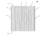
ハニカム構造体の第一実施形態は、図1〜図4に示すようなハニカム構造体100である。ハニカム構造体100は、ハニカム構造部5の外側に、第二外周壁4を更に備えたものである。ハニカム構造部5は、多孔質の隔壁1と、第一外周壁3とを有する。ハニカム構造部5は、隔壁1と第一外周壁3の界面がないものである。即ち、ハニカム構造部5は、隔壁1と第一外周壁3とが連続する1つの構造物であるといえる。ハニカム構造部5の隔壁1は、流入端面11から流出端面12まで延びる流体の流路となる複数のセル2を区画形成するものである。第一外周壁3は、隔壁1の外周の少なくとも一部を取り囲むように配設されている。第二外周壁4は、ハニカム構造部5の外側を囲繞するように配設されている。そして、本実施形態のハニカム構造体100は、セル2の延びる方向に直交する面における第一外周壁3の最大厚さが、0.1〜0.3mmである。
(1) Honeycomb structure (first embodiment):
First embodiment of a honeycomb structure, a
ハニカム構造部5としては、例えば、隔壁1と第一外周壁3とが一体的に構成されたものを挙げることができる。「隔壁1と第一外周壁3とが一体的に構成されたもの」とは、隔壁1と第一外周壁3とが、一度の成形によって形成されたものを意味する。ここで、成形とは、例えば、押出成形を挙げることができる。本実施形態のハニカム構造体100において、ハニカム構造部5は、隔壁1と第一外周壁3とが連続した1つの焼結体によって構成された構造物であると言える。
Examples of the
ここで、図1は、ハニカム構造体の第一実施形態を模式的に示す斜視図である。図2は、図1に示すハニカム構造体の流入端面を模式的に示す平面図である。図3は、図2のX−X’断面を模式的に示す、断面図である。図4は、図2に示すハニカム構造体の、第一外周壁及び第二外周壁の一部を拡大した拡大平面図である。 Here, FIG. 1 is a perspective view schematically showing a first embodiment of a honeycomb structure. FIG. 2 is a plan view schematically showing the inflow end face of the honeycomb structure shown in FIG. FIG. 3 is a cross-sectional view schematically showing the XX ′ cross section of FIG. 2. FIG. 4 is an enlarged plan view in which a part of the first outer peripheral wall and the second outer peripheral wall of the honeycomb structure shown in FIG. 2 is enlarged.
本実施形態のハニカム構造体100は、形状精度に優れるとともに、耐熱衝撃性にも優れるという効果を奏するものである。即ち、本実施形態のハニカム構造体100は、隔壁1と第一外周壁3とが連続した1つの構造物となっており、第一外周壁3の外側に、更に第二外周壁4が配設されている。そして、本実施形態のハニカム構造体100は、第一外周壁3として、最大厚さが0.1〜0.3mmという非常に薄い第一外周壁3を採用している。最大厚さが0.1〜0.3mmの第一外周壁3は、当該第一外周壁3にマイクロクラックが発生し易く、且つ、このようなマイクロクラックは、熱膨張に対する緩衝作用を有している。このため、本実施形態のハニカム構造体100は、第一外周壁3にマイクロクラックを発生させ易くすることにより、このマイクロクラックによる緩衝作用を利用して、ハニカム構造体100全体の耐熱衝撃性の向上を図っている。更に、第一外周壁3を覆うように第二外周壁4を配設することにより、第一外周壁3の強度不足を補いつつ、ハニカム構造体100の形状精度の向上を図っている。
The
第一外周壁3の最大厚さが0.3mmを超えると、第一外周壁3の厚さが厚くなり過ぎることにより、第一外周壁3にマイクロクラックが発生し難くなり、マイクロクラックによる緩衝作用を得ることが困難となる。また、第一外周壁3の最大厚さが0.3mmを超えると、第一外周壁3を覆うように第二外周壁4を配設した場合に、第一外周壁3と第二外周壁4の合計厚さが厚くなり、同じ大きさのハニカム構造体と比較して、流体の流路となるセルの有効断面積が減少してしまう。第一外周壁3の最大厚さが0.1mm未満であると、強度低下により第一外周壁の破損等が発生し易くなる。また、第一外周壁3を全く有していないと、製造時においてハニカム構造部5が変形し易くなり、ハニカム構造体100の形状精度が低下する。以下、特に断りの無い限り、「第一外周壁の厚さ」という場合、セルの延びる方向に直交する面における「第一外周壁の厚さ」を意味する。また、「第二外周壁の厚さ」及び「隔壁の厚さ」という場合についても、セルの延びる方向に直交する面における「第二外周壁の厚さ」及び「隔壁の厚さ」を意味する。
When the maximum thickness of the first outer
第一外周壁3の最大厚さは、0.1〜0.2mmであることが好ましい。このように構成することにより、第一外周壁の破損を抑制しつつ、第一外周壁に発生したマイクロクラックによる緩衝作用をより良好に得ることができる。
The maximum thickness of the first outer
第一外周壁3は、その表面に研削加工等の機械加工が施されたものであってよい。即ち、隔壁1と第一外周壁3とは、一度の押出成形によって形成された一体的な構造物であるが、その製造段階、例えば、押出成形時において、その最大厚さが0.3mmを超えるものであってもよい。例えば、最大厚さが0.3mmを超える第一外周壁3については、第二外周壁4を配設する前に、その表面に対して、研削加工等の公知の機械加工を施して、第一外周壁3の最大厚さを0.3mm以下とすればよい。
The first outer
第一外周壁3の最大厚さは、測定対象のハニカム構造体100の下記に示す3つの断面において、第一外周壁3の厚さを各8点ずつ測定し、測定した24点の厚さのうちの最大値とする。第一外周壁3の厚さを測定する断面としては、ハニカム構造体100の流入端面11側、ハニカム構造体100の流出端面12側、及びハニカム構造体100のセル2の延びる方向の中央の、3つの断面とする。ハニカム構造体100の流入端面11側の断面は、ハニカム構造体100の流入端面11から、セル2の延びる方向の長さの5%以内の任意の断面とする。ハニカム構造体100の流出端面12側の断面は、ハニカム構造体100の流出端面12から、セル2の延びる方向の長さの5%以内の任意の断面とする。ハニカム構造体100のセル2の延びる方向の中央の断面は、ハニカム構造体100のセル2の延びる方向の中央の±5%以内の任意の断面とする。各断面における測定点については、まず、各断面において1つの測定点を決める。そして、この測定点から時計回りに45°ずつ移動した7つ点の測定点を決める。45°ずつ移動した7つ点の測定点に、最初に決めた1つの測定点を加えた8つ測定点を、各断面における測定点とする。
The maximum thickness of the first outer
そして、上記のように測定点を決めた後、各測定点を、走査型電子顕微鏡又はマイクロスコープによって観測し、第一外周壁3の厚さを測定する。第一外周壁3の厚さは、第一外周壁3の表面に対する法線方向の厚さとする。また、第一外周壁3の厚さを測定する際には、第一外周壁3と隔壁1との交差部を観察することで、第一外周壁3と隔壁1との境界の有無の確認することができる。第一外周壁3と隔壁1とに境界がない場合は、第一外周壁3と隔壁1との界面がないと判断することができる。例えば、第一外周壁3と隔壁1とが1つの焼結体によって構成された構造物であれば、第一外周壁3は、隔壁1と一体的に構成されたものということができる。なお、境界の有無の確認は、上述した観測における画像において、第一外周壁3と隔壁1の色調の違いにより判断することができる。例えば、第一外周壁3と隔壁1の組成が異なる場合、第一外周壁3と隔壁1の色調が相違することとなる。また、上記した色調以外にも、例えば、第一外周壁3及び隔壁1を構成するそれぞれの粒子の粒子径や、気孔率等の密度の違いにより、境界の有無の判別を行うこともできる。
And after determining a measurement point as mentioned above, each measurement point is observed with a scanning electron microscope or a microscope, and the thickness of the 1st outer
第一外周壁3と第二外周壁4との境界については、走査型電子顕微鏡又はマイクロスコープ等により拡大した画像にて確認することができる。例えば、上述した画像において、第一外周壁3と第二外周壁4の色調の違いにより、その境界を判別することができる。また、上記した色調以外にも、例えば、第一外周壁3及び第二外周壁4を構成するそれぞれの粒子の粒子径や、気孔率等の密度の違いにより、境界の判別を行うこともできる。
The boundary between the first outer
ハニカム構造体100は、セル2の延びる方向に直交する面において、第二外周壁4の平均厚さが0.8〜1.4mmであることが好ましく、0.8〜1.0mmであること更に好ましい。第二外周壁4の平均厚さが0.8mm未満であると、第一外周壁3が露出することがある点で好ましくない。一方、第二外周壁4の平均厚さが1.4mmを超えると、耐熱衝撃性が低下することがある。
In the
本明細書において、第二外周壁4の平均厚さは、測定対象のハニカム構造体100の3つの断面において、第二外周壁4の厚さを各8点ずつ測定し、測定した合計24点の厚さの平均値とする。第二外周壁4の厚さを測定する方法については、これまでに説明した、第一外周壁3の厚さを測定する方法に準ずるものとする。
In this specification, the average thickness of the second outer
セル2の延びる方向に直交する面において、第一外周壁3の最大厚さと第二外周壁4の平均厚さとの合計が1.0〜1.7mmであることが好ましく、1.0〜1.2mmであること更に好ましい。上記した合計の厚さが1.0mm未満であると、ハニカム構造体の強度が低下することがある。一方、上記した合計の厚さが1.7mmを超えると、耐熱衝撃性が低下することがある。
In the plane perpendicular to the extending direction of the
セル2の延びる方向に直交する面において、第二外周壁4の平均厚さに対する、第一外周壁3の最大厚さの比率が、0.1〜0.3であることが好ましく、0.1〜0.25であること更に好ましい。上記した比率が0.1未満であると、ハニカム構造体の強度が低下することがある。一方、上記した比率が0.3を超えると、耐熱衝撃性が低下することがある。
The ratio of the maximum thickness of the first outer
セル2の延びる方向に直交する面における、セル2の形状については特に制限はない。例えば、セル2の形状としては、三角形、四角形、六角形、八角形、円形、あるいはこれらの組合せを挙げることができる。
There is no particular limitation on the shape of the
隔壁1の厚さは、50〜500μmであることが好ましい。隔壁1の厚さが50μmより薄いと、ハニカム構造体100の強度が低下することがある。隔壁1の厚さが500μmより厚いと、浄化性能が低くなったり、ハニカム構造体にガスが流通するときの圧力損失が大きくなったりすることがある。
The thickness of the
隔壁1の気孔率が、20〜70%であることが好ましい。隔壁1の気孔率が20%未満であると、ハニカム構造体100の圧力損失が増大し、例えば、エンジンの排気系に設置されるPM捕集用のフィルタとして用いた場合に、エンジンの出力低下を招くことがある。また、隔壁の気孔率が70%を超えると、十分な強度が得られないことがある。隔壁の気孔率は、水銀ポロシメータ(Mercury porosimeter)によって計測された値とする。水銀ポロシメータとしては、例えば、Micromeritics社製のAutopore 9500(商品名)を挙げることができる。
It is preferable that the porosity of the
ハニカム構造体100のセル密度は、例えば、15〜200個/cm2であることが好ましい。15個/cm2未満であると、ハニカム構造体100を排ガス浄化用部材として用いた際に、排ガス浄化処理を行う面積が小さくなり、十分な浄化性能が発揮されないことがある。一方、200個/cm2を超えると、ハニカム構造体100にガスが流通するときの圧力損失が大きくなることがある。
The cell density of the
ハニカム構造体100の全体の形状は、例えば、端面の形状が円形、オーバル形等の柱状を挙げることができる。ハニカム構造体の大きさは、例えば、円柱状の場合、底面の直径が、50〜450mmであることが好ましい。また、ハニカム構造体100の中心軸方向の長さは、10〜450mmであることが好ましい。
Examples of the overall shape of the
隔壁1及び第一外周壁3の材質については特に制限はない。例えば、隔壁1及び第一外周壁3の材質としては、セラミックを主成分とするものを挙げることができる。セラミックとしては、コージェライト、炭化珪素、珪素−炭化珪素系複合材料、ムライト、アルミナ、チタン酸アルミニウム、窒化珪素、コージェライト化原料、リチウムアルミニウムシリケート、及び炭化珪素−コージェライト系複合材料から構成される群より選択される少なくとも1種を含む材料を好適例として挙げることができる。「セラミックを主成分とする」というときは、セラミックを全体の50質量%以上含有することを意味する。
There is no restriction | limiting in particular about the material of the
第二外周壁4の材質については特に制限はない。第二外周壁4の材質としては、セラミックを主成分とするものを挙げることができる。第二外周壁の材質としては、隔壁1及び第一外周壁3の材質の好適例として挙げたものと同様のものを挙げることができる。第二外周壁4は、このような材料を含む外周コート材を、第一外周壁3の表面に塗工することによって形成された外周コート層であることがより好ましい。
There are no particular restrictions on the material of the second outer
(2)ハニカム構造体(第二実施形態):
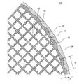
次に、本発明のハニカム構造体の第二実施形態について説明する。第二実施形態のハニカム構造体は、第一外周壁の表面の形状が、凹凸を有した凹凸面であること以外は、これまでに説明した第一実施形態のハニカム構造体と同様に構成されていることが好ましい。ここで、図5は、本発明のハニカム構造体の第二実施形態の流入端面を模式的に示す平面図である。図6は、図5に示すハニカム構造体の、第一外周壁及び第二外周壁の一部を拡大した拡大平面図である。
(2) Honeycomb structure (second embodiment):
Next, a second embodiment of the honeycomb structure of the present invention will be described. The honeycomb structure of the second embodiment is configured in the same manner as the honeycomb structure of the first embodiment described so far, except that the shape of the surface of the first outer peripheral wall is an uneven surface having unevenness. It is preferable. Here, FIG. 5 is a plan view schematically showing the inflow end face of the second embodiment of the honeycomb structure of the present invention. FIG. 6 is an enlarged plan view in which a part of the first outer peripheral wall and the second outer peripheral wall of the honeycomb structure shown in FIG. 5 is enlarged.
図5及び図6に示すように、本実施形態のハニカム構造体200は、ハニカム構造部25と、第二外周壁24と、を備えている。ハニカム構造部25は、多孔質の隔壁21、この隔壁21の外周の少なく一部に配設された第一外周壁23を有するものである。ハニカム構造部25の隔壁21は、流入端面31から流出端面(図示せず)まで延びる流体の流路となる複数のセル22を区画形成するものである。
As shown in FIGS. 5 and 6, the
ハニカム構造部25は、隔壁21と第一外周壁23の界面がないものである。即ち、ハニカム構造体200のハニカム構造部25は、隔壁21と第一外周壁23とが連続した1つの焼結体によって構成された構造物となっている。セル22の延びる方向に直交する面における第一外周壁23の最大厚さは、0.1〜0.3mmである。
The
更に、本実施形態のハニカム構造体200においては、第一外周壁23の表面が、凹凸26を有した凹凸面となっている。このように構成することによって、第一外周壁23にマイクロクラックが発生し易くなる。第一外周壁23の表面の凹凸26は、第一外周壁23の表面の一部に形成されていてもよいし、第一外周壁23の表面の全域に亘って形成されていてもよい。
Furthermore, in the
第一外周壁23の表面に凹凸26を形成する方法としては、ハニカム構造部25の前駆体となるハニカム成形体を押出成形する際に、当該ハニカム成形体の表面に凹凸を形成する方法を挙げることができる。例えば、押出成形時に使用する成形用部材などの条件を適宜設定することにより、その外周面に凹凸が成形されたハニカム成形体を作製することができる。
Examples of the method for forming the
第一外周壁23の表面が凹凸面である場合、セル22の延びる方向に直交する面において、第一外周壁23の表面の周長が、当該第一外周壁23によって囲われる範囲の面積と等価な円の周長に比して大きくなる。本実施形態のハニカム構造体200においては、第一外周壁23の表面の周長が、当該第一外周壁23によって囲われる範囲の面積と等価な円の周長の1.001〜1.003倍の長さであり、1.001〜1.002倍の長さであることが好ましい。
When the surface of the first outer
第一外周壁23の表面の周長は、測定対象のハニカム構造体200の3つの断面において、第一外周壁23の表面の周長をそれぞれ測定し、測定した3つの周長の平均値とする。第一外周壁23の表面の周長を測定する3つ断面としては、ハニカム構造体200の流入端面31側、ハニカム構造体200の流出端面(図示せず)側、及びハニカム構造体200のセル22の延びる方向の中央の、3つの断面とする。周長を測定する3つの断面は、第一外周壁23の厚さを測定するための3つの断面と同じ断面であることが好ましい。それぞれの断面における第一外周壁23の表面の周長は、所定の目盛りを有する測定器具を用いて測定することができる。測定時においては、顕微鏡を用いた拡大像にて測定を行うことが好ましい。測定時における倍率は、例えば、50倍程度である。第一外周壁23の表面の周長は、後述する「波長P」、「第一外周壁23の厚さが最も厚い部分の厚さ」、及び「第一外周壁23の厚さが最も薄い部分の厚さ」の値を用いた理論値として算出することができる。
The peripheral length of the surface of the first outer
第一外周壁23の表面の凹凸面が、波状の波形を有し、当該波形の波長Pが5.1〜8.5mmであり、5.1〜6.4mmであることが好ましい。波形の波長Pは、凹凸面における波形の山から山までの距離とする。波形の波長Pは、第一外周壁23の表面の周長を求める際の顕微鏡を用いた拡大像の測定において、波形の山から山までの距離を測定することによって求めることができる。
Uneven surface of the surface of the first outer
第一外周壁23の表面の凹凸面が、波状の波形を有し、第一外周壁23の最大厚さAmaxと最小厚さAminとの差の値Tが0.1〜0.3mmであることが好ましく、0.1〜0.2mmであることが更に好ましい。「最大厚さAmax」とは、第一外周壁23の表面の波形において、第一外周壁23の厚さが最も厚い部分の厚さのことである。「最小厚さAmin」とは、第一外周壁23の表面の波形において、第一外周壁23の厚さが最も薄い部分の厚さのことである。
The uneven surface on the surface of the first outer
(3)ハニカム構造体の製造方法:
次に、本発明のハニカム構造体を製造する方法について説明する。
(3) Manufacturing method of honeycomb structure:
Next, a method for manufacturing the honeycomb structure of the present invention will be described.
まず、隔壁及び第一外周壁を作製するための可塑性の坏土を作製する。隔壁及び第一外周壁を作製するための坏土は、原料粉末として、前述の隔壁の好適な材料群の中から選ばれた材料に、適宜、バインダ等の添加剤、及び水を添加することによって作製することができる。上記した添加剤としては、有機バインダ、分散剤、界面活性剤等を挙げることができる。有機バインダとしてはヒドロキシプロピルメチルセルロース、メチルセルロース、ヒドロキシプロポキシルセルロース、ヒドロキシエチルセルロース、カルボキシメチルセルロース、ポリビニルアルコール等を挙げることができる。分散剤としては、エチレングリコールを挙げることができる。界面活性剤としては、エチレングリコール、デキストリン、脂肪酸石鹸、ポリアルコール等を挙げることができる。 First, a plastic clay for producing the partition walls and the first outer peripheral wall is produced. The clay for producing the partition walls and the first outer peripheral wall should be appropriately added an additive such as a binder and water to the material selected from the above-mentioned suitable material group of the partition walls as raw material powder. Can be produced. Examples of the additive include an organic binder, a dispersant, and a surfactant. Examples of the organic binder include hydroxypropylmethylcellulose, methylcellulose, hydroxypropoxylcellulose, hydroxyethylcellulose, carboxymethylcellulose, and polyvinyl alcohol. Examples of the dispersant include ethylene glycol. Examples of the surfactant include ethylene glycol, dextrin, fatty acid soap, polyalcohol and the like.
次に、作製した坏土を押出成形することにより、複数のセルを区画形成する隔壁、及び隔壁を囲繞するように配設された第一外周壁を有する、柱状のハニカム成形体を得る。押出成形においては、押出成形用の口金として、坏土の押出面に、成形するハニカム成形体の反転形状となるスリットが形成されたものを用いることができる。成形時における第一外周壁の最大厚さは、0.3mm以下であってもよいし、0.3mmを超えていてもよい。第一外周壁の最大厚さが0.3mmを超える場合には、後述する第二外周壁を形成する工程の前に、公知の機械加工等により、適宜、その最大厚さを0.1〜0.3mmとすることが好ましい。 Next, the formed clay is extruded to obtain a columnar honeycomb formed body having partition walls that form a plurality of cells and a first outer peripheral wall disposed so as to surround the partition walls. In extrusion molding, as the die for extrusion molding, there can be used one in which a slit that is an inverted shape of the honeycomb molded body to be molded is formed on the extruded surface of the clay. The maximum thickness of the first outer peripheral wall at the time of molding may be 0.3 mm or less, or may exceed 0.3 mm. When the maximum thickness of the first outer peripheral wall exceeds 0.3 mm, before the step of forming the second outer peripheral wall to be described later, the maximum thickness is appropriately set to 0.1 to 0.1 by known machining. It is preferable to set it as 0.3 mm.
得られたハニカム成形体を、例えば、マイクロ波及び熱風で乾燥してもよい。また、ハニカム成形体の作製に用いた材料と同様の材料で、セルの開口部を目封止することで目封止部を配設してもよい。 The obtained honeycomb formed body may be dried with, for example, microwaves and hot air. Further, the plugging portions may be disposed by plugging the opening portions of the cells with the same material as that used for manufacturing the honeycomb formed body.
次に、得られたハニカム成形体を焼成することにより、隔壁及び第一外周壁を備えたハニカム構造部を得る。ハニカム構造部とは、第二外周壁が配設される前のハニカム構造体のことである。焼成温度及び焼成雰囲気は、ハニカム成形体の作製に用いた材料により異なり、当業者であれば、選択された材料に最適な焼成温度及び焼成雰囲気を選択することができる。ここで、得られたハニカム構造部の第一外周壁の最大厚さが0.3mmを超える場合には、公知の機械加工等により、適宜、第一外周壁の表面を研削し、その最大厚さを0.1〜0.3mmとすることが好ましい。 Next, the obtained honeycomb formed body is fired to obtain a honeycomb structure portion having partition walls and a first outer peripheral wall. The honeycomb structure portion is a honeycomb structure before the second outer peripheral wall is disposed. The firing temperature and firing atmosphere vary depending on the material used to manufacture the honeycomb formed body, and those skilled in the art can select the optimum firing temperature and firing atmosphere for the selected material. Here, when the maximum thickness of the first outer peripheral wall of the obtained honeycomb structure portion exceeds 0.3 mm, the surface of the first outer peripheral wall is appropriately ground by known machining or the like, and the maximum thickness is obtained. The thickness is preferably 0.1 to 0.3 mm.
次に、第二外周壁を形成するための外周コート材を調製する。外周コート材は、原料粉末として、前述の第二外周壁の好適な材料群の中から選ばれた材料に、適宜、バインダ等の添加剤、及び水を添加することによって作製することができる。 Next, an outer periphery coating material for forming the second outer peripheral wall is prepared. The outer peripheral coating material can be produced by appropriately adding an additive such as a binder and water to a material selected from the above-described suitable material group of the second outer peripheral wall as a raw material powder.
次に、得られた外周コート材を、ハニカム構造部の表面に塗工する。塗工した外周コート材を乾燥し、ハニカム構造部の第一外周壁の表面に、第二外周壁を形成する。外周コート材を乾燥した後、必要に応じて、外周コート材を塗工したハニカム構造部を焼成してもよい。以上のようにして、本発明のハニカム構造体を製造することができる。本発明のハニカム構造体を製造する方法は、これまでに説明した方法に限定されることはない。 Next, the obtained outer periphery coating material is applied to the surface of the honeycomb structure part. The coated outer peripheral coating material is dried to form a second outer peripheral wall on the surface of the first outer peripheral wall of the honeycomb structure part. After the outer periphery coating material is dried, the honeycomb structure coated with the outer periphery coating material may be fired as necessary. As described above, the honeycomb structure of the present invention can be manufactured. The method for manufacturing the honeycomb structure of the present invention is not limited to the methods described so far.
(実施例1)
コージェライト化原料100質量部に、分散媒を35質量部、有機バインダを6質量部、分散剤を0.5質量部、それぞれ添加し、それらを混合し、混練して押出成形用の坏土を調製した。コージェライト化原料としては、アルミナ、水酸化アルミニウム、カオリン、タルク、及びシリカを使用した。分散媒としては水を使用し、造孔材としては平均粒子径1〜10μmのコークスを使用し、有機バインダとしてはヒドロキシプロピルメチルセルロースを使用し、分散剤としてはエチレングリコールを使用した。
(Example 1)
To 100 parts by mass of the cordierite forming material, 35 parts by mass of a dispersion medium, 6 parts by mass of an organic binder, and 0.5 parts by mass of a dispersant are added, mixed, kneaded, and kneaded for extrusion. Was prepared. As the cordierite forming raw material, alumina, aluminum hydroxide, kaolin, talc, and silica were used. Water was used as the dispersion medium, coke having an average particle diameter of 1 to 10 μm was used as the pore former, hydroxypropylmethylcellulose was used as the organic binder, and ethylene glycol was used as the dispersant.
次に、ハニカム成形体作製用の口金を用いて坏土を押出成形し、全体形状が円柱状のハニカム成形体を得た。 Next, the kneaded material was extrusion-molded using a die for manufacturing a honeycomb molded body to obtain a honeycomb molded body having a cylindrical shape as a whole.
次に、ハニカム成形体をマイクロ波乾燥機で乾燥し、更に熱風乾燥機で完全に乾燥させた後、ハニカム成形体の両端面を切断し、所定の寸法に整えた。 Next, the honeycomb formed body was dried with a microwave dryer and further completely dried with a hot air dryer, and then both end faces of the honeycomb formed body were cut and adjusted to a predetermined size.
次に、乾燥したハニカム成形体を、脱脂し、焼成して、隔壁及び第一外周壁を備えたハニカム構造部を得た。得られたハニカム構造部は、端面の直径が190mmで、セルの延びる方向の長さが200mmの円柱状のものであった。隔壁の厚さは110μmであった。第一外周壁の最大厚さは0.1mmであった。セル密度は60個/cm2であった。 Next, the dried honeycomb formed body was degreased and fired to obtain a honeycomb structure portion having partition walls and a first outer peripheral wall. The obtained honeycomb structure portion had a cylindrical shape with an end face diameter of 190 mm and a length in the cell extending direction of 200 mm. The thickness of the partition wall was 110 μm. The maximum thickness of the first outer peripheral wall was 0.1 mm. The cell density was 60 cells / cm 2 .
次に、ハニカム構造部の第一外周壁の表面に、外周コート材を塗工して、塗工した外周コート材を乾燥して第二外周壁を作製した。外周コート材は、コージェライト粒子、コロイダルシリカ、水、分散剤を混合して調製した。 Next, the outer peripheral coating material was applied to the surface of the first outer peripheral wall of the honeycomb structure portion, and the coated outer peripheral coating material was dried to produce a second outer peripheral wall. The outer periphery coating material was prepared by mixing cordierite particles, colloidal silica, water, and a dispersant.
以上のようにして、隔壁及び第一外周壁を有するハニカム構造部と、ハニカム構造部の第一外周壁の外側を囲繞するように配設された第二外周壁と、を備えた、実施例1のハニカム構造体を製造した。第二外周壁の平均厚さは1.0mmであった。表1の「第一外周壁の最大厚さAmax(mm)」及び「第一外周壁の最小厚さAmin(mm)」の欄に、第一外周壁の最大厚さ及び最小厚さを示す。表1の「第二外周壁の平均厚さB(mm)」の欄に、第二外周壁の平均厚さを示す。以下、第一外周壁の最大厚さを「最大厚さAmax」又は単に「厚さAmax」とし、第二外周壁の平均厚さを「平均厚さB」又は単に「厚さB」とする。表1の「厚さAmax+厚さB(mm)」の欄に、第一外周壁の最大厚さAmaxと第二外周壁の平均厚さBとの合計値(mm)を示す。表1の「厚さAmax/厚さB」の欄に、第二外周壁の平均厚さBに対する、第一外周壁の最大厚さAmaxの比率を示す。また、第一外周壁の最大厚さAmaxと最小厚さAmin(mm)の差の値を、表1の「第一外周壁の厚さの差の値」の欄に示す。 As described above, an example including the honeycomb structure portion having the partition walls and the first outer peripheral wall, and the second outer peripheral wall disposed so as to surround the outside of the first outer peripheral wall of the honeycomb structure portion. 1 honeycomb structure was manufactured. The average thickness of the second outer peripheral wall was 1.0 mm. The maximum thickness and the minimum thickness of the first outer peripheral wall in the columns of “Maximum thickness A max (mm) of the first outer peripheral wall” and “Minimum thickness A min (mm) of the first outer peripheral wall” in Table 1. Indicates. In the column of “Average thickness B (mm) of second outer peripheral wall” in Table 1, the average thickness of the second outer peripheral wall is shown. Hereinafter, the maximum thickness of the first outer peripheral wall is “maximum thickness A max ” or simply “thickness A max ”, and the average thickness of the second outer peripheral wall is “average thickness B” or simply “thickness B”. And In the column of “thickness A max + thickness B (mm)” in Table 1, the total value (mm) of the maximum thickness A max of the first outer peripheral wall and the average thickness B of the second outer peripheral wall is shown. In the column of “Thickness A max / Thickness B” in Table 1, the ratio of the maximum thickness A max of the first outer peripheral wall to the average thickness B of the second outer peripheral wall is shown. Further, the value of the difference between the maximum thickness A max and the minimum thickness A min (mm) of the first outer peripheral wall is shown in the column “Value of the difference in thickness of the first outer peripheral wall” in Table 1.
第一外周壁の最大厚さAmax及び最小厚さAminは、測定対象のハニカム構造体の下記に示す3つの断面において、第一外周壁の厚さを各8点ずつ測定し、測定した24点の厚さのうちの最大値及び最小値より求めた。第一外周壁の厚さを測定する断面としては、ハニカム構造体の流入端面側、ハニカム構造体の流出端面側、及びハニカム構造体のセルの延びる方向の中央の、3つの断面とした。ハニカム構造体の流入端面側の断面は、ハニカム構造体の流入端面から、セルの延びる方向の長さの5%以内の任意の断面とした。ハニカム構造体の流出端面側の断面は、ハニカム構造体の流出端面から、セルの延びる方向の長さの5%以内の任意の断面とした。ハニカム構造体のセルの延びる方向の中央の断面は、ハニカム構造体のセルの延びる方向の中央の±5%以内の任意の断面とした。 The maximum thickness A max and the minimum thickness A min of the first outer peripheral wall were measured by measuring the thickness of the first outer peripheral wall at 8 points on each of the following three cross sections of the honeycomb structure to be measured. It calculated | required from the maximum value and the minimum value of the thickness of 24 points | pieces. The cross sections for measuring the thickness of the first outer peripheral wall were three cross sections: the inflow end face side of the honeycomb structure, the outflow end face side of the honeycomb structure, and the center in the cell extending direction of the honeycomb structure. The cross section on the inflow end face side of the honeycomb structure was an arbitrary cross section within 5% of the length in the cell extending direction from the inflow end face of the honeycomb structure. The cross section on the outflow end face side of the honeycomb structure was an arbitrary cross section within 5% of the length in the cell extending direction from the outflow end face of the honeycomb structure. The central cross section in the cell extending direction of the honeycomb structure was an arbitrary cross section within ± 5% of the center in the cell extending direction of the honeycomb structure.
第二外周壁の平均厚さBは、測定対象のハニカム構造体の上述した3つの断面において、第二外周壁の厚さを各8点ずつ測定し、測定した合計24点の厚さの平均値とした。 The average thickness B of the second outer peripheral wall is determined by measuring the thickness of the second outer peripheral wall at 8 points in each of the above-described three cross sections of the honeycomb structure to be measured, and measuring the average thickness of 24 points in total. Value.
実施例1のハニカム構造体について、第一外周壁の表面を以下の方法で観測し、第一外周壁の表面の凹凸の有無を確認した。また、第一外周壁の表面に凹凸が確認された場合には、この凹凸による波形の「波長P」を測定した。結果を、表1に示す。 For the honeycomb structure of Example 1, the surface of the first outer peripheral wall was observed by the following method, and the presence or absence of irregularities on the surface of the first outer peripheral wall was confirmed. Further, when irregularities were confirmed on the surface of the first outer peripheral wall, the “wavelength P” of the waveform due to the irregularities was measured. The results are shown in Table 1.
実施例1のハニカム構造体の第一外周壁の表面の「1つの波形の周長P’」を測定した。「波長P」及び「1つの波形の周長P’」の測定は、顕微鏡を用いた拡大像を、所定の目盛りを有する測定器具にて寸法測定を行うことにより行った。「1つの波形の周長P’」は、波形の一の頂部から隣接する他の頂部までを「1つの波形」とし、第一外周壁の厚さが最も厚い部分の2箇所と、その間に存在する厚さが最も薄い部分の1箇所を直線で結んだ長さとした。また、第一外周壁によって囲われる範囲の面積を求め、求めた面積と等価な円の周長を算出した。第一外周壁の表面の周長は、上記した「等価な円の周長」の1.001倍であった。表1の「周長の倍率」の欄に、上記した「等価な円の周長」に対する「第一外周壁の表面の周長」の倍率を示す。 The “peripheral length P ′ of one waveform” of the surface of the first outer peripheral wall of the honeycomb structure of Example 1 was measured. The measurement of “wavelength P” and “peripheral length P ′ of one waveform” was performed by measuring an enlarged image using a microscope with a measuring instrument having a predetermined scale. The “peripheral length P ′ of one corrugation” is defined as “one corrugation” from one top of the corrugation to another adjacent top, and the two portions of the thickest portion of the first outer peripheral wall are between It was set to the length which tied one place of the thinnest part existing in the straight line. Moreover, the area of the range enclosed by the 1st outer peripheral wall was calculated | required, and the circumference of the circle | round | yen equivalent to the calculated | required area was calculated. The circumference of the surface of the first outer peripheral wall was 1.001 times the above-mentioned “equivalent circumference of the circle”. In the column of “peripheral magnification” in Table 1, the magnification of “peripheral length of the surface of the first outer peripheral wall” with respect to the “peripheral length of the equivalent circle” is shown.

実施例1のハニカム構造体について、以下の方法で、「耐熱衝撃性」、「形状精度」、の評価を行った。また、第一外周壁の表面を顕微鏡によって観察し、第一外周壁の表面にマイクロクラックが形成されているか否かを確認した。結果を、表2に示す。 The honeycomb structure of Example 1 was evaluated for “thermal shock resistance” and “shape accuracy” by the following methods. Further, the surface of the first outer peripheral wall was observed with a microscope, and it was confirmed whether or not microcracks were formed on the surface of the first outer peripheral wall. The results are shown in Table 2.
[耐熱衝撃性]
まず、評価対象のハニカム構造体を焼成炉に投入し、徐々に焼成炉内の温度を上昇させた。ハニカム構造体が規定温度に達した後、焼成炉からハニカム構造体を取り出し、ハニカム構造体を常温まで冷却した。その後、第二外周壁及びハニカム構造部のクラックの有無を確認した。クラックが確認された場合は、ハニカム構造体を加熱した焼成炉内の温度を、クラック発生温度とする。クラックが確認されない場合は、更に焼成炉内の温度を上げた条件でハニカム構造体を加熱し、上述した方法と同様の方法で、再度クラックの有無を確認する。耐熱衝撃性の評価においては、測定されたクラック発生温度に基づき、以下の評価基準によって評価を行った。クラック発生温度が、650℃以上の場合を、評価「A」とする。クラック発生温度が、600℃以上、650℃未満の場合を、評価「B」とする。クラック発生温度が、550℃以上、600℃未満の場合を、評価「C」とする。クラック発生温度が、500℃以上、550℃未満の場合を、評価「D」とする。500℃未満の場合を、評価「E」とする。耐熱衝撃性の評価においては、「A」、「B」、「C」及び「D」の場合を合格とした。
[Thermal shock resistance]
First, the honeycomb structure to be evaluated was put into a firing furnace, and the temperature in the firing furnace was gradually increased. After the honeycomb structure reached the specified temperature, the honeycomb structure was taken out from the firing furnace, and the honeycomb structure was cooled to room temperature. Thereafter, the presence or absence of cracks in the second outer peripheral wall and the honeycomb structure portion was confirmed. When a crack is confirmed, the temperature in the firing furnace which heated the honeycomb structure is made into a crack generation temperature. When no crack is confirmed, the honeycomb structure is heated under the condition that the temperature in the firing furnace is further increased, and the presence or absence of the crack is confirmed again by the same method as described above. In the evaluation of thermal shock resistance, the following evaluation criteria were used based on the measured crack generation temperature. The case where the crack generation temperature is 650 ° C. or higher is evaluated as “A”. The case where crack generation temperature is 600 degreeC or more and less than 650 degreeC is set as evaluation "B". When the crack generation temperature is 550 ° C. or higher and lower than 600 ° C., the evaluation is “C”. The case where crack generation temperature is 500 degreeC or more and less than 550 degreeC is set as evaluation "D". The case of less than 500 ° C. is evaluated as “E”. In the evaluation of thermal shock resistance, the cases of “A”, “B”, “C”, and “D” were accepted.
[形状精度(真円度)]
形状精度の評価については、円柱状のハニカム構造体の真円度を測定して、以下の評価基準に基づいて評価を行った。なお、真円度とは、円形状の幾何学的円からの差の大きさを表すものである。本実施例では、ハニカム構造体の端面における最大径と最小径をノギスで測定し、その差を求めることによって、真円度(mm)を算出した。そして、測定した真円度が、3.2mm以下の場合を「優」とし、真円度が、3.2mmを超え、5.0mm以下の場合を「可」とし、5.0mmを超える場合を「不可」とした。
[Shape accuracy (roundness)]
Regarding the evaluation of the shape accuracy, the roundness of the cylindrical honeycomb structure was measured and evaluated based on the following evaluation criteria. The roundness represents the magnitude of a difference from a circular geometric circle. In this example, the roundness (mm) was calculated by measuring the maximum diameter and the minimum diameter at the end face of the honeycomb structure with a caliper and obtaining the difference therebetween. When the roundness measured is 3.2 mm or less, “excellent”, when the roundness exceeds 3.2 mm, and 5.0 mm or less is “good”, and exceeds 5.0 mm Was “impossible”.
(実施例2〜10)
第一外周壁の最大厚さAmax及び最小厚さAmin並びに第二外周壁の平均厚さBを、表1に示すように変更した以外は、実施例1と同様の方法で、実施例2〜10のハニカム構造体を製造した。第二外周壁の平均厚さBは、外周コート材の塗工量によって調節した。実施例2〜10のハニカム構造体について、実施例1と同様の方法で、「耐熱衝撃性」及び「形状精度」の評価を行った。結果を、表2に示す。
(Examples 2 to 10)
Except that the maximum thickness A max and the minimum thickness A min of the first outer peripheral wall and the average thickness B of the second outer peripheral wall were changed as shown in Table 1, the examples were the same as in Example 1. 2 to 10 honeycomb structures were manufactured. The average thickness B of the second outer peripheral wall was adjusted by the coating amount of the outer peripheral coating material. The honeycomb structures of Examples 2 to 10 were evaluated for “thermal shock resistance” and “shape accuracy” in the same manner as in Example 1. The results are shown in Table 2.
(比較例1〜4)
第一外周壁の最大厚さAmax及び最小厚さAmin並びに第二外周壁の平均厚さBを、表1に示すように変更した以外は、実施例1と同様の方法で、比較例1〜4のハニカム構造体を製造した。第二外周壁の平均厚さBは、外周コート材の塗工量によって調節した。比較例1〜4のハニカム構造体について、実施例1と同様の方法で、「耐熱衝撃性」及び「形状精度」の評価を行った。結果を、表2に示す。
(Comparative Examples 1-4)
Except for changing the maximum thickness A max and minimum thickness A min of the first outer peripheral wall and the average thickness B of the second outer peripheral wall as shown in Table 1, in the same manner as in Example 1, a comparative example 1-4 honeycomb structures were manufactured. The average thickness B of the second outer peripheral wall was adjusted by the coating amount of the outer peripheral coating material. For the honeycomb structures of Comparative Examples 1 to 4, “thermal shock resistance” and “shape accuracy” were evaluated in the same manner as in Example 1. The results are shown in Table 2.
(比較例5〜8)
比較例5〜8においては、実施例1と同様の方法によって、第一外周壁の最大厚さAmax及び最小厚さAminが、表1に示す値となるハニカム構造体を作製した。比較例5〜8のハニカム構造体は、外周コート材を塗工することによって作製された第二外周壁を備えていない、一体型ハニカム構造体である。比較例5〜8のハニカム構造体について、実施例1と同様の方法で、「耐熱衝撃性」及び「形状精度」の評価を行った。結果を、表2に示す。
(Comparative Examples 5 to 8)
In Comparative Examples 5 to 8, honeycomb structures with the maximum thickness A max and the minimum thickness A min of the first outer peripheral wall having the values shown in Table 1 were produced by the same method as in Example 1. The honeycomb structures of Comparative Examples 5 to 8 are integrated honeycomb structures that do not include the second outer peripheral wall produced by applying the outer peripheral coating material. For the honeycomb structures of Comparative Examples 5 to 8, “thermal shock resistance” and “shape accuracy” were evaluated in the same manner as in Example 1. The results are shown in Table 2.
(結果)
実施例1〜10のハニカム構造体は、耐熱衝撃性の評価において、全て合格基準を満たすものであった。また、実施例1〜10のハニカム構造体は、形状精度の評価においても、全て「優」又は「可」の良好な結果を得ることができた。
(result)
The honeycomb structures of Examples 1 to 10 all satisfied the acceptance criteria in the thermal shock resistance evaluation. In addition, the honeycomb structures of Examples 1 to 10 were all able to obtain good results of “excellent” or “good” even in the evaluation of the shape accuracy.
比較例1,2のハニカム構造体は、第一外周壁を有していないため、形状精度の評価において、「不可」という結果となった。 Since the honeycomb structures of Comparative Examples 1 and 2 did not have the first outer peripheral wall, in the evaluation of the shape accuracy, the result was “impossible”.
比較例3,4のハニカム構造体は、耐熱衝撃性の評価において、評価「E」という結果となった。比較例3,4のハニカム構造体は、第一外周壁の最大厚さAmaxが0.3mmを超えるものであったため、第一外周壁が厚くなり、熱膨張に対する緩衝作用を有するマイクロクラックの発生が不十分であったと考えられる。 The honeycomb structures of Comparative Examples 3 and 4 gave an evaluation “E” in the thermal shock resistance evaluation. In the honeycomb structures of Comparative Examples 3 and 4, since the maximum thickness A max of the first outer peripheral wall exceeded 0.3 mm, the first outer peripheral wall became thick, and the microcracks having a buffering action against thermal expansion It is thought that the occurrence was insufficient.
比較例5〜8のハニカム構造体は、耐熱衝撃性の評価においては合格基準を満たしているものの、第二外周壁を備えていないため、形状精度の評価において、「不可」という結果となった。 Although the honeycomb structures of Comparative Examples 5 to 8 satisfied the acceptance criteria in the thermal shock resistance evaluation, they did not include the second outer peripheral wall, and thus the result of the evaluation of the shape accuracy was “impossible”. .
本発明のハニカム構造体は、ガソリンエンジンやディーゼルエンジン等から排出される排ガスを浄化するための触媒を担持する触媒担体や、排ガスを浄化するためのフィルタとして利用することができる。 The honeycomb structure of the present invention can be used as a catalyst carrier that supports a catalyst for purifying exhaust gas discharged from a gasoline engine, a diesel engine, or the like, or as a filter for purifying exhaust gas.
1,21:隔壁、2,22:セル、3,23:第一外周壁、4,24:第二外周壁、5,25:ハニカム構造部、11,31:流入端面、12:流出端面、26:凹凸、100,200:ハニカム構造体、P:波長、T:第一外周壁の最大厚さと最小厚さとの差の値。 1, 2: partition walls, 2, 22: cells, 3, 23: first outer peripheral wall, 4, 24: second outer peripheral wall, 5, 25: honeycomb structure portion, 11, 31: inflow end surface, 12: outflow end surface, 26: Unevenness, 100, 200: Honeycomb structure, P: Wavelength, T: Value of difference between maximum thickness and minimum thickness of first outer peripheral wall.
Claims (5)
前記ハニカム構造部の外側を囲繞するように配設された第二外周壁と、を備え、
前記ハニカム構造部は、前記隔壁と前記第一外周壁の界面がないものであり、且つ、
前記セルの延びる方向に直交する面において、前記第一外周壁の最大厚さが0.1〜0.3mmであり、
前記第一外周壁の表面が、凹凸を有した凹凸面であり、当該凹凸面が、波長が5.1〜8.5mmの波状の波形を有し、
前記セルの延びる方向に直交する面において、前記第一外周壁の表面の周長が、当該第一外周壁によって囲われる範囲の面積と等価な円の周長の1.001〜1.003倍の長さである、ハニカム構造体。 A porous partition wall defining a plurality of cells serving as fluid flow paths extending from the inflow end surface to the outflow end surface, and a honeycomb structure portion having a first outer peripheral wall disposed on at least a part of the outer periphery of the partition wall;
A second outer peripheral wall disposed so as to surround the outside of the honeycomb structure part,
The honeycomb structure portion has no interface between the partition walls and the first outer peripheral wall, and
In a plane perpendicular to the extending direction of the cells, the maximum thickness of the first outer peripheral wall Ri 0.1~0.3mm der,
The surface of the first outer peripheral wall is an uneven surface having unevenness, and the uneven surface has a wavy waveform with a wavelength of 5.1 to 8.5 mm,
In the plane orthogonal to the cell extending direction, the circumference of the surface of the first outer peripheral wall is 1.001 to 1.003 times the circumference of a circle equivalent to the area of the range surrounded by the first outer peripheral wall. length der of Ru, a honeycomb structure.
Priority Applications (4)
| Application Number | Priority Date | Filing Date | Title |
|---|---|---|---|
| JP2017042737A JP6622741B2 (en) | 2017-03-07 | 2017-03-07 | Honeycomb structure |
| US15/906,202 US11339099B2 (en) | 2017-03-07 | 2018-02-27 | Honeycomb structure |
| CN201810165454.2A CN108568209B (en) | 2017-03-07 | 2018-02-28 | Honeycomb structure |
| DE102018001791.6A DE102018001791B4 (en) | 2017-03-07 | 2018-03-06 | honeycomb structure |
Applications Claiming Priority (1)
| Application Number | Priority Date | Filing Date | Title |
|---|---|---|---|
| JP2017042737A JP6622741B2 (en) | 2017-03-07 | 2017-03-07 | Honeycomb structure |
Publications (2)
| Publication Number | Publication Date |
|---|---|
| JP2018143973A JP2018143973A (en) | 2018-09-20 |
| JP6622741B2 true JP6622741B2 (en) | 2019-12-18 |
Family
ID=63259090
Family Applications (1)
| Application Number | Title | Priority Date | Filing Date |
|---|---|---|---|
| JP2017042737A Active JP6622741B2 (en) | 2017-03-07 | 2017-03-07 | Honeycomb structure |
Country Status (4)
| Country | Link |
|---|---|
| US (1) | US11339099B2 (en) |
| JP (1) | JP6622741B2 (en) |
| CN (1) | CN108568209B (en) |
| DE (1) | DE102018001791B4 (en) |
Families Citing this family (4)
| Publication number | Priority date | Publication date | Assignee | Title |
|---|---|---|---|---|
| EP3801827A1 (en) * | 2018-05-31 | 2021-04-14 | Corning Incorporated | Honeycomb bodies with honeycomb structure strengthening features and extrusion dies therefor |
| WO2021138034A1 (en) * | 2020-01-03 | 2021-07-08 | Corning Incorporated | Ceramic honeycomb articles with improved isostatic strength, and method for fabricating same |
| JP7305695B2 (en) * | 2021-03-26 | 2023-07-10 | 日本碍子株式会社 | Method for manufacturing columnar honeycomb fired body |
| JP2022156352A (en) * | 2021-03-31 | 2022-10-14 | 日本碍子株式会社 | honeycomb structure |
Family Cites Families (14)
| Publication number | Priority date | Publication date | Assignee | Title |
|---|---|---|---|---|
| JPH042737Y2 (en) | 1986-04-26 | 1992-01-30 | ||
| JP2892258B2 (en) | 1993-07-29 | 1999-05-17 | 日本碍子株式会社 | Ceramic honeycomb structure |
| CA2119604C (en) | 1993-07-29 | 1997-02-18 | Minoru Machida | Ceramic honeycomb structural body and catalyst comprising the same |
| JP2001261428A (en) | 2000-03-14 | 2001-09-26 | Ngk Insulators Ltd | Ceramic honeycomb structural body |
| US6304999B1 (en) | 2000-10-23 | 2001-10-16 | Advanced Micro Devices, Inc. | Method and apparatus for embedded process control framework in tool systems |
| JP2005230680A (en) | 2004-02-19 | 2005-09-02 | Ngk Insulators Ltd | Honeycomb structure |
| JP4592695B2 (en) * | 2004-05-18 | 2010-12-01 | イビデン株式会社 | Honeycomb structure and exhaust gas purification device |
| CN101959571B (en) * | 2007-10-12 | 2013-06-12 | 日立金属株式会社 | Cordierite ceramic honeycomb filter and process for producing the same |
| JP4998346B2 (en) | 2008-03-25 | 2012-08-15 | 株式会社デンソー | Method for manufacturing ceramic honeycomb structure |
| JP2010001205A (en) * | 2008-05-20 | 2010-01-07 | Ibiden Co Ltd | Honeycomb structure |
| WO2009141892A1 (en) * | 2008-05-20 | 2009-11-26 | イビデン株式会社 | Honeycomb structure |
| JP2013017967A (en) * | 2011-07-12 | 2013-01-31 | Sumitomo Chemical Co Ltd | Honeycomb structure |
| JP5543565B2 (en) | 2012-10-17 | 2014-07-09 | 日本碍子株式会社 | Honeycomb structure |
| US10232299B2 (en) | 2014-09-11 | 2019-03-19 | Ngk Insulators, Ltd. | Honeycomb structure |
-
2017
- 2017-03-07 JP JP2017042737A patent/JP6622741B2/en active Active
-
2018
- 2018-02-27 US US15/906,202 patent/US11339099B2/en active Active
- 2018-02-28 CN CN201810165454.2A patent/CN108568209B/en active Active
- 2018-03-06 DE DE102018001791.6A patent/DE102018001791B4/en active Active
Also Published As
| Publication number | Publication date |
|---|---|
| US20180257998A1 (en) | 2018-09-13 |
| US11339099B2 (en) | 2022-05-24 |
| CN108568209A (en) | 2018-09-25 |
| DE102018001791A1 (en) | 2018-09-13 |
| CN108568209B (en) | 2022-01-11 |
| JP2018143973A (en) | 2018-09-20 |
| DE102018001791B4 (en) | 2022-09-08 |
Similar Documents
| Publication | Publication Date | Title |
|---|---|---|
| JP5144075B2 (en) | Honeycomb structure and manufacturing method thereof | |
| JP5231305B2 (en) | Honeycomb structure and bonded honeycomb structure | |
| JP6622741B2 (en) | Honeycomb structure | |
| JP5771549B2 (en) | Filter element | |
| JP2019171318A (en) | Honeycomb filter | |
| US9890673B2 (en) | Honeycomb filter | |
| JP6110751B2 (en) | Plugged honeycomb structure | |
| US9957861B2 (en) | Honeycomb filter | |
| JP6767914B2 (en) | Honeycomb structure | |
| JP6782659B2 (en) | Honeycomb structure | |
| JP6320798B2 (en) | Honeycomb structure | |
| US20180280961A1 (en) | Honeycomb structure | |
| JP2018122511A (en) | Production method of honeycomb structure, and honeycomb structure | |
| JP6775458B2 (en) | Honeycomb structure | |
| JP6862245B2 (en) | Honeycomb filter | |
| JP6110750B2 (en) | Plugged honeycomb structure | |
| US10730804B2 (en) | Honeycomb structure | |
| JP2018167200A (en) | Honeycomb filter | |
| JP2011056463A (en) | Honeycomb structure | |
| JP5378842B2 (en) | Honeycomb structure | |
| JP2005144250A (en) | Honeycomb structure body | |
| US9555359B2 (en) | Plugged honeycomb structure | |
| JP2018167221A (en) | Honeycomb structure | |
| JP7002393B2 (en) | Honeycomb structure | |
| JP2019171245A (en) | Honeycomb structure |
Legal Events
| Date | Code | Title | Description |
|---|---|---|---|
| A621 | Written request for application examination |
Free format text: JAPANESE INTERMEDIATE CODE: A621 Effective date: 20181012 |
|
| A977 | Report on retrieval |
Free format text: JAPANESE INTERMEDIATE CODE: A971007 Effective date: 20190628 |
|
| A131 | Notification of reasons for refusal |
Free format text: JAPANESE INTERMEDIATE CODE: A131 Effective date: 20190709 |
|
| A521 | Request for written amendment filed |
Free format text: JAPANESE INTERMEDIATE CODE: A523 Effective date: 20190902 |
|
| TRDD | Decision of grant or rejection written | ||
| A01 | Written decision to grant a patent or to grant a registration (utility model) |
Free format text: JAPANESE INTERMEDIATE CODE: A01 Effective date: 20191105 |
|
| A61 | First payment of annual fees (during grant procedure) |
Free format text: JAPANESE INTERMEDIATE CODE: A61 Effective date: 20191122 |
|
| R150 | Certificate of patent or registration of utility model |
Ref document number: 6622741 Country of ref document: JP Free format text: JAPANESE INTERMEDIATE CODE: R150 |