JP6620088B2 - Illumination system and illumination optical unit for EUV projection lithography - Google Patents
Illumination system and illumination optical unit for EUV projection lithography Download PDFInfo
- Publication number
- JP6620088B2 JP6620088B2 JP2016515545A JP2016515545A JP6620088B2 JP 6620088 B2 JP6620088 B2 JP 6620088B2 JP 2016515545 A JP2016515545 A JP 2016515545A JP 2016515545 A JP2016515545 A JP 2016515545A JP 6620088 B2 JP6620088 B2 JP 6620088B2
- Authority
- JP
- Japan
- Prior art keywords
- individual
- mirror
- field
- illumination
- mirrors
- Prior art date
- Legal status (The legal status is an assumption and is not a legal conclusion. Google has not performed a legal analysis and makes no representation as to the accuracy of the status listed.)
- Active
Links
- 238000005286 illumination Methods 0.000 title claims description 183
- 230000003287 optical effect Effects 0.000 title claims description 53
- 238000001459 lithography Methods 0.000 title claims description 8
- 210000001747 pupil Anatomy 0.000 claims description 54
- 230000008859 change Effects 0.000 claims description 51
- 238000006073 displacement reaction Methods 0.000 claims description 43
- 238000003384 imaging method Methods 0.000 claims description 24
- 230000004048 modification Effects 0.000 claims description 18
- 238000012986 modification Methods 0.000 claims description 18
- 238000009826 distribution Methods 0.000 description 16
- 230000005855 radiation Effects 0.000 description 13
- 238000012937 correction Methods 0.000 description 9
- 230000000694 effects Effects 0.000 description 9
- 238000000034 method Methods 0.000 description 5
- 238000000926 separation method Methods 0.000 description 5
- 230000007423 decrease Effects 0.000 description 4
- 230000012447 hatching Effects 0.000 description 3
- 239000004065 semiconductor Substances 0.000 description 3
- 230000007704 transition Effects 0.000 description 3
- 230000004075 alteration Effects 0.000 description 2
- 230000008901 benefit Effects 0.000 description 2
- 230000000295 complement effect Effects 0.000 description 2
- 238000010586 diagram Methods 0.000 description 2
- 238000009304 pastoral farming Methods 0.000 description 2
- 238000007493 shaping process Methods 0.000 description 2
- 230000007480 spreading Effects 0.000 description 2
- 238000003892 spreading Methods 0.000 description 2
- 230000001360 synchronised effect Effects 0.000 description 2
- 230000000007 visual effect Effects 0.000 description 2
- 230000005540 biological transmission Effects 0.000 description 1
- 230000003247 decreasing effect Effects 0.000 description 1
- 230000001419 dependent effect Effects 0.000 description 1
- 238000013461 design Methods 0.000 description 1
- 239000003574 free electron Substances 0.000 description 1
- 230000010354 integration Effects 0.000 description 1
- 238000004519 manufacturing process Methods 0.000 description 1
- 239000011159 matrix material Substances 0.000 description 1
- 238000005259 measurement Methods 0.000 description 1
- 230000007246 mechanism Effects 0.000 description 1
- 238000001393 microlithography Methods 0.000 description 1
- 230000007935 neutral effect Effects 0.000 description 1
- 238000005457 optimization Methods 0.000 description 1
- 238000013139 quantization Methods 0.000 description 1
- 230000009467 reduction Effects 0.000 description 1
- 230000002441 reversible effect Effects 0.000 description 1
- 238000003860 storage Methods 0.000 description 1
- 238000012546 transfer Methods 0.000 description 1
Images


Classifications
-
- G—PHYSICS
- G03—PHOTOGRAPHY; CINEMATOGRAPHY; ANALOGOUS TECHNIQUES USING WAVES OTHER THAN OPTICAL WAVES; ELECTROGRAPHY; HOLOGRAPHY
- G03F—PHOTOMECHANICAL PRODUCTION OF TEXTURED OR PATTERNED SURFACES, e.g. FOR PRINTING, FOR PROCESSING OF SEMICONDUCTOR DEVICES; MATERIALS THEREFOR; ORIGINALS THEREFOR; APPARATUS SPECIALLY ADAPTED THEREFOR
- G03F7/00—Photomechanical, e.g. photolithographic, production of textured or patterned surfaces, e.g. printing surfaces; Materials therefor, e.g. comprising photoresists; Apparatus specially adapted therefor
- G03F7/70—Microphotolithographic exposure; Apparatus therefor
- G03F7/70058—Mask illumination systems
- G03F7/702—Reflective illumination, i.e. reflective optical elements other than folding mirrors, e.g. extreme ultraviolet [EUV] illumination systems
-
- G—PHYSICS
- G03—PHOTOGRAPHY; CINEMATOGRAPHY; ANALOGOUS TECHNIQUES USING WAVES OTHER THAN OPTICAL WAVES; ELECTROGRAPHY; HOLOGRAPHY
- G03F—PHOTOMECHANICAL PRODUCTION OF TEXTURED OR PATTERNED SURFACES, e.g. FOR PRINTING, FOR PROCESSING OF SEMICONDUCTOR DEVICES; MATERIALS THEREFOR; ORIGINALS THEREFOR; APPARATUS SPECIALLY ADAPTED THEREFOR
- G03F7/00—Photomechanical, e.g. photolithographic, production of textured or patterned surfaces, e.g. printing surfaces; Materials therefor, e.g. comprising photoresists; Apparatus specially adapted therefor
- G03F7/70—Microphotolithographic exposure; Apparatus therefor
- G03F7/70058—Mask illumination systems
- G03F7/70075—Homogenization of illumination intensity in the mask plane by using an integrator, e.g. fly's eye lens, facet mirror or glass rod, by using a diffusing optical element or by beam deflection
-
- G—PHYSICS
- G03—PHOTOGRAPHY; CINEMATOGRAPHY; ANALOGOUS TECHNIQUES USING WAVES OTHER THAN OPTICAL WAVES; ELECTROGRAPHY; HOLOGRAPHY
- G03F—PHOTOMECHANICAL PRODUCTION OF TEXTURED OR PATTERNED SURFACES, e.g. FOR PRINTING, FOR PROCESSING OF SEMICONDUCTOR DEVICES; MATERIALS THEREFOR; ORIGINALS THEREFOR; APPARATUS SPECIALLY ADAPTED THEREFOR
- G03F7/00—Photomechanical, e.g. photolithographic, production of textured or patterned surfaces, e.g. printing surfaces; Materials therefor, e.g. comprising photoresists; Apparatus specially adapted therefor
- G03F7/70—Microphotolithographic exposure; Apparatus therefor
- G03F7/70058—Mask illumination systems
- G03F7/70091—Illumination settings, i.e. intensity distribution in the pupil plane or angular distribution in the field plane; On-axis or off-axis settings, e.g. annular, dipole or quadrupole settings; Partial coherence control, i.e. sigma or numerical aperture [NA]
- G03F7/70116—Off-axis setting using a programmable means, e.g. liquid crystal display [LCD], digital micromirror device [DMD] or pupil facets
Description
ドイツ特許出願第10 2013 218 749.1号明細書の内容が、引用によって本明細書に組み込まれている。 The contents of German Patent Application No. 10 2013 218 749.1 are hereby incorporated by reference.
本発明は、リソグラフィマスクが配置可能である物体視野に向けて照明光を案内するためのEUV投影リソグラフィのための照明光学ユニットに関する。本発明は、更に、特にそのような照明光学ユニットを含む照明系、そのような照明系を含む投影露光装置、そのような投影露光装置を用いて微細又はナノ構造化構成要素、特に半導体構成要素を生成する方法、及び本方法によって生成された微細又はナノ構造化構成要素に関する。 The present invention relates to an illumination optical unit for EUV projection lithography for guiding illumination light towards an object field on which a lithographic mask can be placed. The invention further provides an illumination system comprising such an illumination optical unit, a projection exposure apparatus comprising such an illumination system, a micro- or nanostructured component using such a projection exposure apparatus, in particular a semiconductor component And a micro- or nanostructured component produced by the method.
冒頭に示したタイプの照明光学ユニットは、WO 2010/037453 A1、WO 2010/104163 A、WO 2008/149178 A1、US 2011/0001947 A1、US 2009/0041182 A1、及びDE 10 2006 036 064 A1から公知である。
Illumination optical units of the type indicated at the beginning are known from WO 2010/037453 A1, WO 2010/104163 A, WO 2008/149178 A1, US 2011/0001947 A1, US 2009/0041182 A1, and
照明の目的は、照明光学ユニットの異なる照明チャネルを通じて案内された照明光を予め定められた照明パラメータを同じく予め定められた許容範囲で遵守しながら可能な限り損失のない方式で照明視野内で重ねることである。 The purpose of the illumination is to superimpose the illumination light guided through different illumination channels of the illumination optical unit in the illumination field in a manner that is as lossless as possible while also complying with predetermined illumination parameters in the same predetermined tolerances. That is.
本発明の目的は、照明の最適化、特に、異なる照明チャネルを通じて案内された照明光の照明視野内での最適な重ね合わせを与える照明光学ユニットを提供することである。 It is an object of the present invention to provide an illumination optical unit that provides illumination optimization, in particular an optimal superposition within the illumination field of illumination light guided through different illumination channels.
本発明により、上述の目的は、当初請求項1に指定する特徴及び当初請求項8に指定する特徴を有する照明光学ユニット、並びに当初請求項11に指定する特徴を有する照明系を用いて達成される。
The present invention, the above object is achieved initially illumination optical unit having the characteristics specified in features and
本発明は、個別ミラー群が物体視野内に、これらの個別ミラー群の像が各々物体視野を完全に覆うように結像されるという概念から離脱する。各々物体視野を完全に覆う像を有する個別ミラー群を以下では完全個別ミラー群とも呼ぶ。上述の境界条件を廃棄することにより、更に割り当てられる瞳ファセットを通して物体視野に結像される個別ミラー群への視野ファセットミラーの個別ミラーの割り当ての新しい自由度がもたらされる。本発明により、次に、物体視野を完全には覆わない像をもたらす個別ミラー群も許容される。物体視野を完全には覆わない像を有するそのような個別ミラー群を以下では分別個別ミラー群とも呼ぶ。分別個別ミラー群は、視野ファセットミラーを配置することが意図されるEUV光源の遠視野の実際のプロファイルに視野ファセットミラーの外側輪郭を非常に的確に適応させる可能性をもたらす。例えば、これらの個別ミラー群を使用すると、同一のサイズ及び形状の群を用いてそのような遠視野領域をタイル張りすることがもはや必要ではなく、従って、ここで、そのようなタイル張りを用いては回避することができない遠視野の縁部領域における損失を回避することができる。上述の境界条件を廃棄することにより、これまでには可能ではなかった方式で遠視野を利用する可能性が提供される。一例として、視野ファセットミラーの個別ミラーによって遠視野区域の80%よりも大きい比率、例えば、85%さえも超える比率、又はより一層大きい百分率を覆うことができる。遠視野区域を区切る縁部は、最大遠視野照明光強度の強度割合(強度比)krが入射する遠視野の外側境界として定められる。割合(比)krは、例えば、値0.1、0.05、又は更に小さい値とすることができる。krは、値1/e又は1/e2を有することができる。 The present invention departs from the concept that the individual mirror groups are imaged within the object field, and the images of these individual mirror groups are each imaged to completely cover the object field. Individual mirror groups each having an image that completely covers the object field are also referred to as complete individual mirror groups. Discarding the above boundary conditions provides a new degree of freedom for the assignment of the individual mirrors of the field facet mirrors to the individual mirror groups that are imaged in the object field through the further assigned pupil facets. The present invention also allows for individual mirror groups that in turn yield an image that does not completely cover the object field. Such an individual mirror group having an image that does not completely cover the object field is also referred to as a fractional individual mirror group in the following. The group of separate individual mirrors offers the possibility to adapt the outer contour of the field facet mirror very accurately to the actual profile of the far field of the EUV light source intended to place the field facet mirror. For example, using these individual mirror groups, it is no longer necessary to tile such a far-field region with groups of the same size and shape, so here we use such tiles. Loss in the edge region of the far field that cannot be avoided. By discarding the boundary conditions described above, the possibility of using far field in a manner not previously possible is provided. As an example, the individual mirrors of the field facet mirror can cover a proportion greater than 80% of the far field area, for example a proportion greater than 85%, or even a larger percentage. Edges delimiting the far field zone, the maximum intensity ratio of the far-field illumination light intensity (intensity ratio) k r is defined as an outer boundary of the far-field incident. Ratio (ratio) k r can be, for example, a value 0.1,0.05, or even smaller. k r may have a value 1 / e or 1 / e 2.
個別ミラー群への個別ミラーの割り当てにおいて新しく与えられる柔軟性は、この割り当てを照明パラメータ及び/又は結像効果の補正又は補償に向けて使用することを可能にする。その例は、当初請求項1及び当初請求項8に記載の照明光学ユニットによって与えられる。次に、視野ファセットミラー上の与えられた個数の個別ミラーを用いて多数の個別ミラー群を形成することができ、相応に多数の瞳ファセットが同時に照明光による入射を受けることができる。それによって照明角度分布の事前定義、すなわち、物体視野照明に対する照明設定の事前定義において高い柔軟性がもたらされる。瞳ファセットも、個々の小さいファセットミラーの群として構成することができる。同時に入射を受けることができる瞳ファセットの個数に個別ミラー群毎の個別ミラーの公称個数を乗じたものが、視野ファセットミラー上の個別ミラーの実際の個数よりも多い個数をもたらすそのような照明光学ユニットが、逆方向に、すなわち、物体視野から照明される場合に、又は投影光学ユニットを用いて物体視野が像視野に結像される場合に、第1の強度を有する光による入射を受ける照明セクションと、第2のより高い、特に2倍高い強度で入射を受ける更に別の照明セクションとで構成されるパターンが像視野から視野ファセットミラー上に向けられる。そのような逆露光中により高い強度で入射を受けるこれらの視野ファセットセクション内には、照明光が同時に入射することができる異なる瞳ファセットに任意的に割り当てることができるファセットミラーの個別ミラーが配置される。より高い強度で照明される視野ファセットセクションは、個別ミラーの公称個数よりも少ない個数の個別ミラーを有する。 The new flexibility provided in the assignment of individual mirrors to individual mirror groups makes it possible to use this assignment towards correction or compensation of illumination parameters and / or imaging effects. Examples are provided by the illumination optical unit according to original claim 1 and initially claim 8. Then, a given number of individual mirrors on the field facet mirror can be used to form a large number of individual mirror groups, and correspondingly a large number of pupil facets can be simultaneously illuminated by the illumination light. This provides a high degree of flexibility in predefining the illumination angle distribution, ie predefining the illumination settings for object field illumination. The pupil facets can also be configured as a group of individual small facet mirrors. Such illumination optics, where the number of pupil facets that can be incident simultaneously multiplied by the nominal number of individual mirrors for each group of individual mirrors results in a number that is greater than the actual number of individual mirrors on the field facet mirror Illumination that is incident by light having a first intensity when the unit is illuminated in the reverse direction, i.e. from the object field, or when the object field is imaged into the image field using a projection optical unit A pattern composed of sections and a further illumination section receiving a second higher, in particular twice as high intensity, is directed from the image field onto the field facet mirror. Within these field facet sections receiving higher intensity during such backexposure are arranged individual mirrors of facet mirrors that can be arbitrarily assigned to different pupil facets on which the illumination light can enter simultaneously. The A field facet section that is illuminated at a higher intensity has a smaller number of individual mirrors than the nominal number of individual mirrors.
物体視野高さへの走査積分照明強度の依存性の補正又は補償に向けて、個別ミラー群は、例えば対応する遠視野分布に起因して内部により高い照明強度が元来存在している視野高さ領域内により小さい走査積分広がりを有する群形状が使用されるように分割することができる。これに代えて又はこれに加えて、個別ミラー群が、反射に使用することができない楔形面積領域を通して互いに隣接することを前提としない結像傾斜の補正又は補償が可能である。 To correct for or compensate for the dependence of the scan integral illumination intensity on the object field height, the individual mirror groups are for example field heights where higher illumination intensity originally exists due to the corresponding far-field distribution, for example. It can be divided such that a group shape having a smaller scan integral spread in the vertical region is used. Alternatively or in addition to this, it is possible to correct or compensate for the imaging tilt which does not assume that the individual mirror groups are adjacent to each other through a wedge-shaped area that cannot be used for reflection.
原理的には視野ファセットミラーの全ての個別ミラーによって反射される光を使用することができるので、可能な限り大きい遠視野比率の使用又は照明パラメータ及び/又は結像効果の補正又は補償は、損失なく実施することができる。当然ながらこれに代えて、照明パラメータ及び/又は結像の更に別の影響に向けて選択される個別ミラーの光が物体視野の照明に寄与しないように、これらの個別ミラーの光を目標を定めた方式で遮蔽することが可能である。 In principle, the light reflected by all the individual mirrors of the field facet mirror can be used, so the use of the largest possible far field ratio or the correction or compensation of illumination parameters and / or imaging effects is a loss. Can be implemented without. Naturally, instead of this, the light of these individual mirrors is targeted so that the light of the individual mirrors selected for further influence of the illumination parameters and / or imaging does not contribute to the illumination of the object field. It is possible to shield by different methods.
当初請求項2に記載の少なくとも1つの変更セクションは、この変更セクションに隣接するそれぞれ望ましい他の個別ミラー群への個別ミラーの柔軟なグループ分けを可能にする。少なくとも1つの変更セクションは、物体変位方向に対して垂直な物体視野の広がりの半分よりも小さく、例えば、物体変位方向に対して垂直な物体視野の広がりの40%、35%、30%、又は更に小さい百分率に対応する広がりを物体変位方向と垂直に有することができる。
At least one new section according to
少なくとも1つの変更セクションは、完全個別ミラー群の広がりの5%と80%の間に達する広がりを有することができる。 At least one modification section may have a spread that reaches between 5% and 80% of the spread of the complete individual mirror group.
当初請求項3及び当初請求項4に記載の像位置の差は、個別ミラー群を通じた物体視野の重ね合わせ照明中の強度及び/又は結像に影響する際の対応する自由度をもたらす。
The difference of the image position according to the
当初請求項5又は当初請求項6に記載の変更セクションにおける個別ミラーの配置は、走査積分照明強度の典型的な視野高さ依存性の補正又は補償を可能にする。
Arrangement of the individual mirrors in the new section of originally described in
当初請求項7に記載の変更セクションにおける個別ミラーの配置は、視野高さにわたる走査積分照明強度に関して中立である。 The arrangement of the individual mirrors in the modified section as originally claimed in claim 7 is neutral with respect to the scan integral illumination intensity over the field height.
当初請求項9に記載の変更セクションの設計は、結像傾斜の補正又は補償に特に適することが見出されている。それぞれの個別ミラーの寸法の範囲では物体変位方向に対して垂直な座標軸において物体変位方向に沿う変更セクションの広がりにはほぼ増大がないことを除いて、物体変位方向に対して垂直な座標軸における物体変位方向に沿う変更セクションの広がりの増大は、厳密に単調なものとすることができ、特に直線的なものとすることができる。従って、個別ミラーの有限の広がりに起因する変更セクションの広がりの量子化は、この厳密に単調な増大、特に直線的な増大の場合は無視される。 The design of the modified section as originally claimed in claim 9 has been found to be particularly suitable for correction or compensation of the imaging tilt. The object in the coordinate axis perpendicular to the object displacement direction, except that the extent of the change section along the object displacement direction in the coordinate axis perpendicular to the object displacement direction is not substantially increased in the dimension range of each individual mirror. The increase in the extent of the change section along the direction of displacement can be strictly monotonic and in particular linear. Thus, the quantization of the change section spread due to the finite spread of the individual mirrors is ignored in the case of this strictly monotonic increase, in particular a linear increase.
上述の利点は、特に当初請求項11及び当初請求項12に記載の照明系に適用される。
Advantages described above are applied to the illumination system according to a particularly
当初請求項10に記載の照明系、当初請求項13に記載の光学系、当初請求項14に記載の投影露光装置、及び当初請求項15に記載の生成方法の利点は、照明系及び照明光学ユニットを参照して上述したものに対応する。この生成方法によって微細又はナノ構造化構成要素を生成することができる。そのような構成要素は、高い構造分解能で生成することができる。このようにして、例えば、高い集積又はストレージ密度を有する半導体チップを生成することができる。
[当初請求項1]
リソグラフィマスク(7)が、配置可能であり、かつ投影露光中に物体変位方向(4)に沿って変位可能である物体視野(5)に向けて照明光(16)を案内するためのEUV投影リソグラフィのための照明光学ユニット(4)であって、
少なくとも2つの傾斜位置の間で切り換えることができ、かつ照明光部分ビームを前記物体視野(5)に向けて案内するための個別ミラー照明チャネルを与える多数の個別ミラー(27)を含む視野ファセットミラー(19)を含み、
前記照明光(16)のビーム経路内で前記視野ファセットミラー(19)の下流に配置された複数の静止瞳ファセット(20a)を含む瞳ファセットミラー(20)を含み、該瞳ファセット(20a)は、各場合に、群ミラー照明チャネルを通じた前記物体視野(5)内への該視野ファセットミラー(19)の前記個別ミラー(27)の群(25)の少なくとも区画的な重ね合わせ結像に寄与し、
前記瞳ファセット(20a)のそれぞれ1つが、結像されることになる前記個別ミラーの前記群(25)のうちのそれぞれ1つに割り当てられ、
前記物体視野(5)内に完全に結像可能である個別ミラー群(25)が、公称個数の個別ミラー(27)を有し、
照明光が前記個別ミラー群を通じて同時に入射することができる前記瞳ファセット(20a)の個数に個別ミラー群(25)毎の前記個別ミラー(27)の前記公称個数を乗じたものが、前記視野ファセットミラー(19)上の該個別ミラー(27)の実際の個数よりも多い個数の個別ミラー(27)を結果として生じ、
前記個別ミラー群(25)への前記個別ミラーの割り当てが、この割り当てが前記物体変位方向(4)に沿って積分される照明光強度の該物体変位方向(y)に対して垂直な物体視野高さ(x)への依存性の補正に使用されるようなものである、
ことを特徴とする照明光学ユニット(4)。
[当初請求項2]
前記個別ミラー(27)の少なくとも一部が、前記視野ファセットミラー(19)の少なくとも1つの変更セクション(36)に配置され、該変更セクション(36;50,51)内の該個別ミラー(27)は、前記個別ミラー傾斜位置に基づいて、異なる瞳ファセット(20a)を通じて前記物体視野(5)内に結像される2つの異なる個別ミラー群(25a,25b)に割り当てられ、
前記変更セクション(36)は、前記物体視野(5)に結像されて前記物体変位方向に対して垂直な該物体視野(5)の広がりの最大で半分に達する該物体変位方向に対して垂直な広がりを有する、
ことを特徴とする当初請求項1に記載の照明光学ユニット。
[当初請求項3]
前記変更セクション(36a,36b)は、前記変更領域(36)に配置された個別ミラー(27 i )が、前記個別ミラー傾斜位置に基づいて、すなわち、それぞれの前記個別ミラー群(25a,25b)へのその割り当てに基づいて、走査方向(y)に対して垂直(x)な前記物体視野(5)の広がり(x 0 )の10%よりも大きい該走査方向(y)に対して垂直(x)な互いからの距離を有する像位置(41,42)に結像されるように配置されることを特徴とする当初請求項2に記載の照明光学ユニット。
[当初請求項4]
前記変更セクション(50,51)は、該変更セクション(50,51)内に配置された個別ミラー(27 j ,27 k )が、前記個別ミラー傾斜位置に基づいて、すなわち、それぞれの前記個別ミラー群(50,51)へのその割り当てに基づいて、走査方向(y)の前記物体視野(5)の広がり(y 0 )の40%よりも大きい該走査方向(y)の互いからの距離を有する像位置(52,53;54,55)に結像されるように配置されることを特徴とする当初請求項2又は当初請求項3に記載の照明光学ユニット。
[当初請求項5]
前記変更セクション(36)内に前記個別ミラー(27)を含む2つの前記個別ミラー群(25a,25b)が、より多い個数の個別ミラー照明チャネルを通じて前記物体視野の中心領域にかつ該物体視野(5)の縁部領域に該物体視野(5)上への前記物体変位方向に沿って積分された照明光入射をもたらすような前記視野ファセットミラー(19)の該変更セクション(36)内の該個別ミラーの割り当て(36a,36b)を特徴とする当初請求項2から当初請求項4のいずれか1項に記載の照明光学ユニット。
[当初請求項6]
前記変更セクション(36)内に前記個別ミラー(27)を含む2つの前記個別ミラー群(25a,25b)が、前記物体視野(5)の中心領域内よりも多い個数の個別ミラー照明チャネルを通じて該物体視野(5)の縁部領域に該物体視野(5)上への前記物体変位方向に沿って積分された照明光入射をもたらすような前記視野ファセットミラー(19)の該変更セクション内の該個別ミラー(27)の割り当て(36c,36d)を特徴とする当初請求項2から当初請求項4のいずれか1項に記載の照明光学ユニット。
[当初請求項7]
前記変更セクション(36)内に前記個別ミラー(27)を含む2つの前記個別ミラー群(25a,25b)が、前記物体視野(5)の中心領域内よりもいくつかの個別ミラー照明チャネルを通じて該物体視野(5)の縁部領域に該物体視野(5)上への前記物体変位方向に沿って積分された照明光入射をもたらすような前記視野ファセットミラー(19)の該変更セクション(36)内の該個別ミラー(27)の割り当て(36e,36f)を特徴とする当初請求項2に記載の照明光学ユニット。
[当初請求項8]
リソグラフィマスク(7)が、配置可能であり、かつ投影露光中に物体変位方向(4)に沿って変位可能である物体視野(5)に向けて照明光(16)を案内するためのEUV投影リソグラフィのための照明光学ユニット(4)であって、
少なくとも2つの傾斜位置の間で切り換えることができ、かつ照明光部分ビームを前記物体視野(5)に向けて案内するための個別ミラー照明チャネルを与える多数の個別ミラー(27)を含む視野ファセットミラー(19)を含み、
前記照明光(16)のビーム経路内で前記視野ファセットミラー(19)の下流に配置された複数の静止瞳ファセット(20a)を含む瞳ファセットミラー(20)を含み、該瞳ファセット(20a)は、各場合に、群ミラー照明チャネルを通じた前記物体視野(5)内への該視野ファセットミラー(19)の前記個別ミラー(27)の群(25)の少なくとも区画的な重ね合わせ結像に寄与し、
前記瞳ファセット(20a)のそれぞれ1つが、結像されることになる前記個別ミラーの前記群(25)のうちのそれぞれ1つに割り当てられ、
前記物体視野(5)内に完全に結像可能である個別ミラー群(25)が、公称個数の個別ミラー(27)を有し、
照明光が前記個別ミラー群を通じて同時に入射することができる前記瞳ファセット(20a)の個数に個別ミラー群(25)毎の前記個別ミラー(27)の前記公称個数を乗じたものが、前記視野ファセットミラー(19)上の該個別ミラー(27)の実際の個数よりも多い個数の個別ミラー(27)を結果として生じ、
前記個別ミラー群(25)への前記個別ミラーの割り当てが、この割り当てが前記物体視野(5)内へのそれぞれの該個別ミラー群(25)の結像傾斜の補正に使用されるようなものである、
ことを特徴とする照明光学ユニット(4)。
[当初請求項9]
前記個別ミラー(27)の少なくとも一部が、前記視野ファセットミラー(19)の変更セクション(50,51)に配置され、該変更セクション(50,51)内の該個別ミラー(27)は、前記個別ミラー傾斜位置に基づいて、異なる瞳ファセット(20a)を通じて前記物体視野(5)内に結像される2つの異なる個別ミラー群(25c/d,25d/e)に割り当てられ、
前記変更セクション(50,51)は、前記物体変位方向に対して垂直な寸法において単調に増大する該物体変位方向に沿った広がりを有する、
ことを特徴とする当初請求項8に記載の照明光学ユニット。
[当初請求項10]
当初請求項1から当初請求項9のいずれか1項に記載の照明光学ユニットを含み、
EUV光源(2)を含む、
ことを特徴とする照明系(3)。
[当初請求項11]
リソグラフィマスク(7)が、配置可能であり、かつ投影露光中に物体変位方向(y)に沿って変位可能である物体視野(5)に向けて照明光(16)を案内するためのEUV投影リソグラフィのための照明光学ユニット(4)を含む照明系(3)であって、
照明系(3)のEUV光源(2)の遠視野(56)に配置され、少なくとも2つの傾斜位置の間で切り換え可能であって前記物体視野(5)に向けて照明光部分ビームを案内するための個別ミラー照明チャネルを与える多数の個別ミラー(27)を含む視野ファセットミラー(19)を含み、
前記個別ミラー(27)は、割り当てられる瞳ファセット(20a)を通じてそれぞれの個別ミラー群(25)を前記物体視野(5)内に結像する目的に対して、前記照明光(16)のビーム経路内で前記視野ファセットミラー(19)の下流に配置された瞳ファセットミラー(20)の該瞳ファセット(20a)に各場合に割り当てられる該個別ミラー群(25)にグループ分け可能であり、
前記個別ミラー群(25)のこのようにして生成された像が、前記物体視野(5)内で少なくとも部分的に重ね合わされ、
前記視野ファセットミラー(19)の前記個別ミラー(27)は、前記遠視野(56)の面積の少なくとも80%の比率が該個別ミラー(27)によって覆われ、そのために後者が前記照明光(16)を反射するように前記光源(2)の該遠視野(56)に配置される、
ことを特徴とする照明系(3)。
[当初請求項12]
前記照明光(16)を反射する前記個別ミラー(27)は、前記物体視野(5)内に結像されることを特徴とする当初請求項11に記載の照明系。
[当初請求項13]
当初請求項1から当初請求項9のいずれか1項に記載の照明光学ユニットを含み、
物体視野(5)を像視野(11)内に結像するための投影光学ユニット(10)を含む、
ことを特徴とする光学系。
[当初請求項14]
当初請求項10から当初請求項12のいずれか1項に記載の照明系(3)を含み、
EUV光源(2)を含み、
物体(7)を物体視野(5)に装着するためのものであって、物体変位ドライブ(9)を用いて変位方向(y)に沿って変位可能である物体ホルダ(8)を含み、
ウェーハ(13)を像視野(11)に装着するためのものであって、ウェーハ変位ドライブ(15)を用いて前記変位方向(y)に沿って変位可能であるウェーハホルダ(14)を含む、
ことを特徴とする投影露光装置(1)。
[当初請求項15]
投影露光の方法であって、
当初請求項14に記載の投影露光装置(1)を与える段階と、
ウェーハ(13)を与える段階と、
リソグラフィマスク(7)を与える段階と、
前記投影露光装置(1)の投影光学ユニット(10)を用いて前記リソグラフィマスク(7)の少なくとも一部を前記ウェーハ(13)の感光層の領域の上に投影する段階と、 を含むことを特徴とする方法。
Lighting system according to
[Initial claim 1]
EUV projection for directing illumination light (16) towards an object field (5) in which a lithographic mask (7) is positionable and can be displaced along the object displacement direction (4) during projection exposure An illumination optical unit (4) for lithography comprising:
Field facet mirror comprising a number of individual mirrors (27) which can be switched between at least two tilt positions and provide individual mirror illumination channels for guiding the illumination light partial beam towards said object field (5) Including (19),
A pupil facet mirror (20) including a plurality of stationary pupil facets (20a) disposed downstream of the field facet mirror (19) in the beam path of the illumination light (16), the pupil facet (20a) , In each case contributing to at least compartmental superposition imaging of the group (25) of the individual mirrors (27) of the field facet mirror (19) into the object field (5) through a group mirror illumination channel And
Each one of the pupil facets (20a) is assigned to a respective one of the groups (25) of the individual mirrors to be imaged,
A group of individual mirrors (25) that are fully imageable in the object field (5) has a nominal number of individual mirrors (27);
The field facet is obtained by multiplying the number of the pupil facets (20a) to which illumination light can simultaneously enter through the individual mirror group by the nominal number of the individual mirrors (27) for each individual mirror group (25). Resulting in a greater number of individual mirrors (27) than the actual number of individual mirrors (27) on the mirror (19),
Assignment of the individual mirrors to the individual mirror group (25) is an object field perpendicular to the object displacement direction (y) of the illumination light intensity where this assignment is integrated along the object displacement direction (4) Such as those used to correct for dependence on height (x),
An illumination optical unit (4) characterized in that.
[Initial claim 2]
At least a part of the individual mirror (27) is arranged in at least one modified section (36) of the field facet mirror (19), and the individual mirror (27) in the modified section (36; 50, 51) Are assigned to two different groups of individual mirrors (25a, 25b) imaged in the object field (5) through different pupil facets (20a) based on the individual mirror tilt positions;
The modified section (36) is perpendicular to the object displacement direction that is imaged in the object field (5) and reaches up to half of the extent of the object field (5) perpendicular to the object displacement direction. Has a wide spread,
2. An illumination optical unit according to claim 1, wherein
[Initial claim 3]
In the change section (36a, 36b), the individual mirror (27 i ) arranged in the change area (36) is based on the individual mirror tilt position, that is, the individual mirror group (25a, 25b). Perpendicular to the scanning direction (y), which is greater than 10% of the extent (x 0 ) of the object field (5) perpendicular (x) to the scanning direction (y) 3. The illumination optical unit according to
[Initial claim 4]
The change section (50, 51) is configured so that the individual mirrors (27 j , 27 k ) arranged in the change section (50, 51) are based on the individual mirror tilt position, that is, each of the individual mirrors. Based on its assignment to the group (50, 51), a distance from each other in the scanning direction (y) that is greater than 40% of the extent (y 0 ) of the object field (5) in the scanning direction (y). The illumination optical unit according to
[Initial claim 5]
Two individual mirror groups (25a, 25b) including the individual mirror (27) in the modification section (36) are connected to the central area of the object field through a larger number of individual mirror illumination channels and to the object field ( 5) in the modified section (36) of the field facet mirror (19) to bring the illumination light incident along the object displacement direction onto the object field (5) into the edge region of the field field (5) 5. An illumination optical unit according to any one of
[Initial claim 6]
Two groups of individual mirrors (25a, 25b) including the individual mirrors (27) in the modification section (36) pass through a greater number of individual mirror illumination channels than in the central region of the object field (5). The field facet mirror (19) in the modified section of the field facet mirror (19) in such a way that an illumination light incidence integrated along the object displacement direction onto the object field (5) is provided at the edge region of the object field (5). 5. An illumination optical unit according to any one of
[Initial claim 7]
Two groups of individual mirrors (25a, 25b) including the individual mirrors (27) in the modification section (36) can pass through several individual mirror illumination channels rather than in the central region of the object field (5). The modified section (36) of the field facet mirror (19) to bring the illumination light incident integrated along the direction of object displacement onto the object field (5) into the edge region of the object field (5) 3. An illumination optical unit according to
[Initial claim 8]
EUV projection for directing illumination light (16) towards an object field (5) in which a lithographic mask (7) is positionable and can be displaced along the object displacement direction (4) during projection exposure An illumination optical unit (4) for lithography comprising:
Field facet mirror comprising a number of individual mirrors (27) which can be switched between at least two tilt positions and provide individual mirror illumination channels for guiding the illumination light partial beam towards said object field (5) Including (19),
A pupil facet mirror (20) including a plurality of stationary pupil facets (20a) disposed downstream of the field facet mirror (19) in the beam path of the illumination light (16), the pupil facet (20a) , In each case contributing to at least compartmental superposition imaging of the group (25) of the individual mirrors (27) of the field facet mirror (19) into the object field (5) through a group mirror illumination channel And
Each one of the pupil facets (20a) is assigned to a respective one of the groups (25) of the individual mirrors to be imaged,
A group of individual mirrors (25) that are fully imageable in the object field (5) has a nominal number of individual mirrors (27);
The field facet is obtained by multiplying the number of the pupil facets (20a) to which illumination light can simultaneously enter through the individual mirror group by the nominal number of the individual mirrors (27) for each individual mirror group (25). Resulting in a greater number of individual mirrors (27) than the actual number of individual mirrors (27) on the mirror (19),
The assignment of the individual mirrors to the individual mirror group (25) is such that this assignment is used to correct the imaging tilt of each individual mirror group (25) in the object field (5) Is,
An illumination optical unit (4) characterized in that.
[Initial claim 9]
At least a part of the individual mirror (27) is arranged in a modified section (50, 51) of the field facet mirror (19), and the individual mirror (27) in the modified section (50, 51) Assigned to two different groups of individual mirrors (25c / d, 25d / e) imaged in the object field (5) through different pupil facets (20a) based on the individual mirror tilt positions;
The modified section (50, 51) has a spread along the object displacement direction that monotonically increases in a dimension perpendicular to the object displacement direction.
9. The illumination optical unit according to
[Initial claim 10]
Including the illumination optical unit according to any one of claims 1 to 9;
Including an EUV light source (2),
An illumination system (3) characterized by that.
[Initial claim 11]
EUV projection for directing illumination light (16) towards an object field (5) in which a lithographic mask (7) can be placed and can be displaced along the object displacement direction (y) during projection exposure An illumination system (3) comprising an illumination optical unit (4) for lithography,
Located in the far field (56) of the EUV light source (2) of the illumination system (3), switchable between at least two tilt positions and guide the illumination light partial beam towards the object field (5) A field facet mirror (19) including a number of individual mirrors (27) to provide individual mirror illumination channels for
The individual mirror (27) is configured to beam the illumination light (16) for the purpose of imaging each individual mirror group (25) in the object field (5) through an assigned pupil facet (20a). Can be grouped into the individual mirror group (25) assigned in each case to the pupil facet (20a) of the pupil facet mirror (20) arranged downstream of the field facet mirror (19),
The images thus generated of the individual mirror group (25) are at least partially superimposed in the object field (5),
The individual mirror (27) of the field facet mirror (19) is covered by the individual mirror (27) at least 80% of the area of the far field (56), so that the latter is the illumination light (16 ) In the far field (56) of the light source (2) to reflect
An illumination system (3) characterized by that.
[Initial claim 12]
12. Illumination system according to
[Initial claim 13]
Including the illumination optical unit according to any one of claims 1 to 9;
A projection optical unit (10) for imaging the object field (5) into the image field (11);
An optical system characterized by that.
[Initial claim 14]
Including the illumination system (3) according to any one of the
Including an EUV light source (2),
An object holder (8) for mounting an object (7) in an object field (5), which is displaceable along a displacement direction (y) using an object displacement drive (9);
A wafer holder (14) for mounting the wafer (13) in the image field (11), which is displaceable along the displacement direction (y) using a wafer displacement drive (15);
The projection exposure apparatus (1) characterized by the above-mentioned.
[Initial claim 15]
A projection exposure method,
Providing a projection exposure apparatus (1) according to claim 14 initially;
Providing a wafer (13);
Providing a lithographic mask (7);
To include the steps of projecting onto a region of the photosensitive layer of the wafer (13) at least part of the lithographic mask (7) with a projection optical unit (10) of the projection exposure apparatus (1) Feature method.
図面を参照して本発明の例示的実施形態を下記でより詳細に説明する。 Exemplary embodiments of the invention are described in more detail below with reference to the drawings.
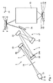
図1は、マイクロリソグラフィのための投影露光装置1を子午断面図に略示している。投影露光装置1は、光源又は放射線源2を含む。投影露光装置1の照明系3は、物体平面6の物体視野5と一致する照明視野を露光するための照明光学ユニット4を有する。この場合に、物体視野5に配置され、物体ホルダ又はレチクルホルダ8によって保持されたレチクル7の形態にある物体が露光される。レチクル7をリソグラフィマスクとも呼ぶ。物体ホルダ8は、物体変位ドライブ9を用いて変位方向に沿って変位可能である。投影光学ユニット10は、物体視野5を像平面12の像視野11に結像するためなどに機能する。レチクル7上の構造は、像平面12の像視野11の領域に配置されたウェーハ13の感光層上に結像される。ウェーハ13は、ウェーハホルダ(同じく例示していない)によって保持される。ウェーハホルダ14もまた、ウェーハ変位ドライブ15を用いて物体ホルダ8と同期方式で変位方向に沿って変位可能である。
FIG. 1 schematically shows a projection exposure apparatus 1 for microlithography in a meridional section. The projection exposure apparatus 1 includes a light source or a
放射線源2は、5nmと30nmの間の範囲の放出使用放射線を有するEUV放射線源である。放射線源2は、プラズマ光源、例えば、GDPP(ガス放電生成プラズマ)光源又はLPP(レーザ生成プラズマ)光源とすることができる。放射線源2に、シンクロトロン又は自由電子レーザ(FEL)を利用する放射線源を使用することができる。当業者は、そのような放射線源に関する情報を例えばUS 6,859,515 B2に見出すことができるであろう。放射線源2から射出したEUV放射線16は、コレクター17によってフォーカスされる。対応するコレクターは、EP 1 225 481 Aから公知である。コレクター17の下流では、EUV放射線16は、中間焦点面18を通って伝播し、その後に、視野ファセットミラー19上に入射する。視野ファセットミラー19は、照明光学ユニット4の第1のファセットミラーである。視野ファセットミラー19は、複数の個別ミラー(図1には例示していない)を有する。視野ファセットミラー19は、物体平面6に対して光学的に共役な照明光学ユニット4の平面に配置される。
The
以下ではEUV放射線16を照明光又は結像光とも呼ぶ。
Hereinafter, the
視野ファセットミラー19の下流において、EUV放射線16は、瞳ファセットミラー20によって反射される。瞳ファセットミラー20は、照明光学ユニット4の第2のファセットミラーである。瞳ファセットミラー20は、中間焦点面18及び投影光学ユニット10の瞳平面に対して光学的に共役である又はこの瞳平面と一致する照明光学ユニット4の瞳平面に配置される。瞳ファセットミラー20は複数の瞳ファセット20aを有し、図1にはそのうちの2つの瞳ファセット20aを略示している。瞳ファセットミラー20の瞳ファセットと、ビーム経路の順番に命名したミラー22、23、及び24を含む伝達光学ユニット21とを用いて、下記で更に詳しく説明する視野ファセットミラー19の個別ミラー群25(例えば、図2を参照されたい)が物体視野5に結像される。伝達光学ユニット21の最後のミラー24は、かすめ入射のためのミラー(「かすめ入射ミラー」)である。
Downstream of the
位置関係の説明を容易にするために、図1は、物体平面6と像平面12の間の投影露光装置1の構成要素の位置関係の説明のための広域座標系として直交xyz座標系を描示している。図1では、x軸は作図面と垂直に、その中に入り込むように延びている。図1では、y軸は右に向けて、物体ホルダ8及びウェーハホルダ14の変位方向と平行に延びている。z軸は図1の下向きに、すなわち、物体平面6及び像平面12と垂直に延びている。
In order to facilitate the explanation of the positional relationship, FIG. 1 depicts an orthogonal xyz coordinate system as a wide-area coordinate system for explaining the positional relationship of the components of the projection exposure apparatus 1 between the object plane 6 and the
物体視野5又は像視野11にわたるx寸法を視野高さとも呼ぶ。
The x dimension over the
図2は、視野ファセットミラー19のセグメントの構成の詳細を示している。図2に示す視野ファセットミラー19のセグメントは、例えば、個別ミラー群25のうちの正確に1つのものである。視野ファセットミラー19の全体の反射面26が、行列で個別ミラー27の格子に再分割され、すなわち、個別ミラーアレイを構成する。それぞれの個別ミラー27を通して照明光16の部分ビームが案内される。特定の個別ミラー27の個々の反射面は、凹面様式に具現化される。特定の個別ミラー27の個々の反射面の別の可能な実施形態において、これらの反射面は平面であり、曲率を持たない。個別ミラー行28は、互いに直接に横並びで置かれた複数の個別ミラー27を有する。個別ミラー行28内には数十個から数百個の個別ミラー27を設けることができる。図2に記載の例では、個別ミラー27は正方形である。反射面26をいかなる間隙もなく可能な限り覆うことを可能にする他の形状の個別ミラーを使用することができる。そのような別の個別ミラー形状は、タイル張りの数学理論から公知である。この点に関しては、WO 2009/100 856 A1に示されている参考文献を参照されたい。
FIG. 2 shows details of the configuration of the segments of the
視野ファセットミラー19の実施形態に基づいて、個別ミラー列29も同じく複数の個別ミラー27を有する。一例として、個別ミラー列29毎に数十個又は数百個の個別ミラー27が設けられる。
Based on the embodiment of the
位置関係の説明を容易にするために、図2は、視野ファセットミラー19の局所座標系として直交xyz座標系を描示している。ファセットミラー又はそのセグメントを平面図に示すその後の図においても、対応する局所xyz座標系を示している。図2では、x軸は、右に向けて個別ミラー行28と平行に水平に延びている。図2では、y軸は、個別ミラー列29と平行に上方に延びている。z軸は、図2の作図面に対して垂直であり、そこから出るように延びている。
In order to facilitate the explanation of the positional relationship, FIG. 2 shows an orthogonal xyz coordinate system as the local coordinate system of the
図1に記載の広域座標系のy方向、すなわち、走査方向とも呼ぶレチクル7及びウェーハ13に対する変位方向と、図2に記載の局所座標系のy方向、すなわち、各場合に広域座標系のxy平面に投影された個別ミラーアレイの列方向とは、互いに対して正確に平行に延びる必要はなく、互いに対してある角度、例えば、小さい角度を取ることができる。ミラー24による視野成形効果は、局所座標系のy方向と広域座標系のy方向の間の偏向を局所的にもたらす可能性もある。
The y direction of the wide area coordinate system shown in FIG. 1, that is, the displacement direction with respect to the reticle 7 and the
個別ミラー群25の反射面26は、x方向にx0の広がりを有する。y方向には、個別ミラー群25の反射面26はy0の広がりを有する。
The reflecting
視野ファセットミラー19の実施形態に基づいて、個別ミラー27は、例えば500μm×500μmから例えば2mm×2mmの範囲のx/y広がりを有する。個別ミラー27は、照明光16に対してフォーカス効果を有するように成形することができる。個別ミラー27のそのようなフォーカス効果は、照明光16によるファセットミラー19の発散照明を使用する場合に特に有利である。視野ファセットミラー19全体は、実施形態に基づいて、例えば、300mm×300mm又は600mm×600mmのx/y広がりを有する。個別ミラー群25(図7を参照されたい)は、80mm×6mm、65mm×5mm、25mm×4mm、又は104mm×8mmの標準x0/y0広がりを有する。個別ミラー群25が物体視野5内に完全に結像される限り、個別ミラー群25のx0/y0アスペクト比は、物体視野5のx/yアスペクト比に対応することができる。実際には、個別ミラー群のアスペクト比は物体視野のアスペクト比から外れ、物体視野のアスペクト比よりも大きい場合がある。それぞれの個別ミラー群25のサイズと、個別ミラー群25を構成する個別ミラー27のサイズとの比に基づいて、個別ミラー群25の各々は、対応する個数の個別ミラー27を有する。個別ミラー群の像が物体視野5を完全に覆う程多くの個別ミラー27を個別ミラー群が含む場合に限り、個別ミラー群を以下では完全個別ミラー群とも呼ぶ。
Based on the embodiment of the
入射照明光16の個々の偏向に向けて、図2で反射面26の左下コーナに配置された2つの個別ミラー27を基に破線に示すように、個別ミラー27の各々は、アクチュエータ30にそれぞれ接続される。アクチュエータ30は、個別ミラー27の各々の反射側から離れる方向に向く側面上に配置される。アクチュエータ30は、例えば、圧電アクチュエータとして具現化することができる。そのようなアクチュエータの構成は、マイクロミラーアレイの構造から公知である。
As shown by the broken lines based on the two
個別ミラー行28のアクチュエータ30は、それぞれ行信号バス32に信号線を通して接続される。個別ミラー行28は、各場合に行信号バス32のうちの1つに割り当てられる。個別ミラー行28の行信号バス32自体は、主信号バス33に接続される。主信号バス33は、視野ファセットミラー19の制御デバイス34に信号接続される。制御デバイス34は、特に個別ミラー27を直列に互いに、すなわち、行毎又は列毎に駆動するように設計される。個別ミラー行28内及び個別ミラー列29内であっても個別ミラー27の個々の駆動が可能である。
The
個別ミラー27の各々は、2つの互いに垂直な傾斜軸の周りに個々に傾斜可能であり、これらの傾斜軸のうちの第1のものは、x軸と平行に延び、これら2つの傾斜軸のうちの第2のものは、y軸と平行に延びている。2つの傾斜軸は、それぞれの個別ミラー27の個々の反射面内で延びている。 Each of the individual mirrors 27 can be individually tilted about two mutually perpendicular tilt axes, the first of these tilt axes extending parallel to the x-axis, The second of them extends parallel to the y-axis. The two tilt axes extend in the respective reflecting surfaces of the respective individual mirrors 27.
視野ファセットミラー19の個別ミラー構成の更なる詳細に関しては、US 2011/0001947 A1を参照されたい。
For further details of the individual mirror configuration of the
既に上述のように、少なくとも2つの個別ミラー27から各々構成される個別ミラー群25への個別ミラー27の予め定められた傾斜グループ分けは、制御デバイス34を用いたアクチュエータ30の個々の駆動によって設定することができる。個別ミラー群25は、照明光16に対する少なくとも1つの専用群ミラー照明チャネルを通じて個別ミラー群25を物体視野5に結像するための瞳ファセットミラー20の少なくとも1つの専用瞳ファセット20aにそれぞれ割り当てられる。この割り当ては、それぞれの個別ミラー27上に入射する照明光16の部分ビームが、当該の個別ミラー27から瞳ファセットミラー20の割り当て瞳ファセットに向けて、更にそこから物体視野5に向けて反射されるような個別ミラー群25に属する個別ミラー27のそれぞれの傾斜位置又は切り換え位置の事前定義によって達成される。この場合に、群ミラー照明チャネルは、照明視野又は物体視野5を照明するための瞳ファセット20aを経由する結像に起因して互いに相補し合うそれぞれの個別ミラー群25の全ての個別ミラー照明チャネルの全体である。従って、個別ミラー群25の各々は、照明視野5の少なくとも1つのセクションの原像と見なすことができる。この場合に、照明視野5の原像は、結像収差に考慮した上で像視野5内に正確に結像される構造形態である。この構造形態を実原像とも呼ぶ。それとは対照的に、照明視野5の理想的な原像は、結像収差を考慮せずに像視野5内に正確に結像される構造形態を表している。
As already mentioned above, the predetermined tilt grouping of the individual mirrors 27 into
照明視野又は物体視野5の全体照明は、次に、これらの原像の重ね合わせを構成する。
The overall illumination of the illumination field or object
従って、基本的に個別ミラー群25の各々は、US 6,438,199 B1又はUS 6,658,084 B2に開示されているもののような視野ファセットミラーのファセットの機能を有する。
Thus, basically each
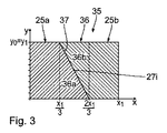
図3は、視野ファセットミラー19のセグメント35を平面図に示している。セグメント35の範囲にある個別ミラー(個々には例示していない)は、異なる瞳ファセット20aを通して物体視野5に結像される2つの個別ミラー群25a、25bに割り当てられる。図3では、セグメント35の範囲にある2つの個別ミラー群25a、25bを異なるハッチングで例示している。
FIG. 3 shows a
セグメント35は、x方向にx1という広がりを有し、y方向にy1という広がりを有する。アスペクト比x1/y1に関して次式が成り立つ。
x1/y1=3/2 x0/y0
The
x 1 / y 1 = 3/2 x 0 / y 0
従って、2つの個別ミラー群25a、25bを有するセグメント35のx/yアスペクト比は、物体視野5のx/yアスペクト比よりも50%大きい。
Accordingly, the x / y aspect ratio of the
視野ファセットミラー19のセグメント35は、走査方向yに対して垂直なx方向に3つのセクションに再分割される。これらのセクションの各々は、以下で[xi;xj]とも説明する2つの視野高さxiとxjの間の領域を構成する。
The
セクション[0;x1/3]内では、セグメント35の全ての個別ミラーは、正確に1つの第1の瞳ファセット20aに割り当てられる。同じくセクション[2/3 x1;x1]、すなわち、そこに配置された個別ミラー27は、他の瞳ファセット20aに割り当てられる。セクション[0;x1/3]の範囲にあるセグメント35の全ての個別ミラーを傾斜させることにより、例えば、照明設定が変更された時に、これらの個別ミラーを第1の瞳ファセット20aの定義群に対して異なる第1の瞳ファセット20aに割り当てることができる。この割り当て変更は、セグメント35のセクション[0;x1/3]の範囲にある全ての個別ミラーに対して常に一緒に行われる。相応に同じことは、セクション[2/3 x1;x1]内の個別ミラーにも適用され、第1の瞳ファセット20aの異なる群がここで関わっている。
Section; Within [0 x 1/3], all of the individual mirrors of the
これらの2つのセクションの間には、視野ファセットミラー19のセグメント35の変更セクション36が領域[1/3 x1;2/3 x1]に位置する。変更セクション36は、(x,y)座標(x1/3,y1)と(2/3 x1,0)の間の分離線37を用いて2つの変更サブセクション36a、36bに再分割される。変更サブセクション36aは、x座標[0;1/3 x1]を有するセクションと共に、個別ミラー群25aを形成する。変更サブセクション36bは、x座標[2/3 x1;x1]を有するセクションと共に個別ミラー群25bを形成する。変更サブセクション36a、36bへの変更セクション36のこの再分割は、そこに配置された個別ミラー27の傾斜位置を用いて行われる。この場合に、個別ミラー27は、個別ミラー群25a、25bとの関係に基づいて、2つの個別ミラー群25a、25bのそれぞれの1つ内の全ての個別ミラー27が共通の瞳ファセット20aを通して照明光16を案内するように傾斜される。
Between these two sections, the modified
変更セクション36は、x方向、すなわち、物体変位方向yと垂直に広がりx1/3を有し、すなわち、広がりx0/2に結像スケールβを乗じた広がりで物体視野5に結像される。以下では簡略化の目的で、例えば、それぞれの個別ミラー群25の広がりx0が物体視野広がりx0に等しくなるように、この結像スケールβがβ=1であると仮定する。従って、物体変位方向yに対して垂直な変更セクション36の広がりは、物体変位方向yに対して垂直な物体視野5の広がりx0の半分で物体視野5に結像される。
図4は、照明強度分布Iに対する2つの個別ミラー群25a、25bへのセグメント35の再分割の効果を視野高さ範囲[−x0/2;+x0/2]の物体視野5の視野高さxの関数として示している。この場合に、個別ミラー群25aの強度寄与38を破線形式で例示しており、個別ミラー群25bの強度寄与39を一点鎖線形式で例示している。視野高さxにわたる全強度寄与40を実線形式で例示している。強度寄与38から40は、走査方向yにわたって積分されるそれぞれの視野高さxの場所に例示したものである。この場合に、視野ファセットミラー19のセグメント35が一定の照明強度I0で入射を受けると仮定している。
4, illumination intensity two
範囲[−x0/2;0]内の個別ミラー群25aの強度寄与38は、最初に値I0において一定であるように推移する。走査方向yにわたって積分されるこれらの視野高さでは、セグメント35の全体のy幅が物体視野照明に寄与する。
Range [-x 0/2; 0] intensity contribution 38 of the
視野高さ範囲[0;x0/2]内では、強度寄与38は、値I0から値0まで直線的に減少する。この減少は、個別ミラー群25aの変更サブセクション36aのy広がりが、x=2/3 x1における個別ミラー群25aの縁部領域に至るまで相応に直線的に値0まで減少することでもたらされる。
Within the field height range [0; x 0/2 ], the
個別ミラー群25bの強度寄与39は、相応に鏡像反転されたものである。変更サブセクション36bは、物体視野内で直線的に増大する強度寄与がもたらされるように視野高さ範囲[x0/2;0]内で物体視野照明に寄与する。視野高さ範囲[0;x0/2]内では、I=I0において一定の強度寄与39がもたらされる。
The
分離線37による変更セクション36の再分割に起因して、視野高さx=0において最大照明強度2I0を有し、両方の縁部−x0/2、x0/2に向けて照明強度I0まで直線的に減少する屋根形推移を有する全強度寄与40が2つの強度寄与38、39の和としてもたらされる。
Due to the subdivision of the
従って、図3に記載の変更セクション36の再分割は、物体視野5の中心領域内、すなわち、x=0の領域内で物体視野5の縁部領域、すなわち、x=│x0/2│の領域内よりも多い個別ミラー照明チャネルにわたる物体変位方向yに沿って積分される物体視野5の照明光入射を生成する。
Thus, subdivision of
物体視野5全体を覆う像を有する個別ミラー群25内の個別ミラー27の全個数を以下では個別ミラー群25毎の個別ミラー27の公称個数とも呼ぶ。
Hereinafter, the total number of
結像によって物体視野5を完全に覆うそのような個別ミラー群を以下では完全個別ミラー群とも呼ぶ。従って、図2に記載の個別ミラー群25は、完全個別ミラー群である。
Such an individual mirror group that completely covers the
物体視野5の一部分しか覆わない像を有する個別ミラー群を以下では分別個別ミラー群とも呼ぶ。従って、図3に記載の個別ミラー群25a、25bは分別個別ミラー群である。
The individual mirror group having an image that covers only a part of the
分別個別ミラー群25a、25b内の個別ミラー27の全個数は、物体視野5全体を覆う像を有する図2に記載の完全個別ミラー群25内の個別ミラー27の全個数よりも少ない。これは、分別個別ミラー群25a、25bが、各場合に全体の変更セクション36を含まず、各場合に変更セクション36のサブセクション36a、36bのみを含むことに起因する。従って、個別ミラー群25a、25bの像は、物体視野5の一部分、図示の実施形態の場合は物体視野5の全面積の正確に75%を覆う。視野ファセットミラー19上の個別ミラー群25a、25bに対応する分別個別ミラー群の面積要件は、物体視野5全体を覆う像を有する図2に記載の個別ミラー群25に対応する完全個別ミラー群の面積要件よりも相応に小さい。全体的な視野ファセットミラー19の反射面26の与えられた面積、又は全体的な視野ファセットミラー19の個別ミラー27の与えられた全個数を仮定し、変更サブセクション36a、36bに対応する変更サブセクションを部分的に有するそのような分別個別ミラー群を使用すると、照明光16は、各場合に物体視野5全体を覆う像を有する完全個別ミラー群26への再分割の場合よりも多い個数の瞳ファセット20a上に入射することができる。この場合に、視野ファセットミラー19の個別ミラー群25を経由した照明光16による入射を同時に受けることができる瞳ファセット20aの個数に完全個別ミラー群25の公称個数を乗じたものは、結果として視野ファセットミラー19上の個別ミラー27の実際の個数よりも多い個数の個別ミラー27の個数をもたらす。
The total number of
従って、次式が成り立つ。
NPF×NN>NESP
Therefore, the following equation holds.
N PF × N N > N ESP
この場合に、NPFは、瞳ファセットミラー20の同時に使用される瞳ファセット20aの個数である。
In this case, N PF is the number of
NNは、完全個別ミラー群25毎の個別ミラー27の公称個数である。
N N is the nominal number of
NESPは、視野ファセットミラー19全体の個別ミラー27の個数である。
N ESP is the number of
視野高さxへの全強度寄与40の依存性、及び分別個別ミラー群25a、25bへの個別ミラー27の対応する割り当ては、物体変位方向yに沿って積分される照明光強度の物体視野高さxへの依存性の補正に使用することができる。
The dependence of the
図5は、物体視野5の平面図を略示している。物体視野5は、視野高さ寸法x内に範囲[−x0/2;x0/2]内にあるx0の広がりを有する。y方向、すなわち、走査方向には、物体視野5は、y=y0の広がりを有する。第1に図2に記載の完全個別ミラー群25のx方向及びy方向の広がりと、第2に物体視野5のx方向及びy方向の広がりとは、当然ながら個別ミラー群が物体視野5内に1という結像スケールで結像される場合にのみ同一である。この場合に、y1=y0及びx1=x0が成り立つ。他の場合に、第1にそれぞれの完全個別ミラー群25の寸法と、第2に物体視野5の寸法とは、当然ながら各場合にx方向及びy方向の結像スケールだけ異なる。
FIG. 5 schematically shows a plan view of the
図5は、変更セクション36の中心にある選択された個別ミラー27iの個別ミラー像41、42を示している。個別ミラー27iは、それが変更セクション部分群36a又は変更セクション部分群36bのいずれに属するかに基づいて、個別ミラー像41又は個別ミラー像42のいずれかの上に結像される。個別ミラー像41、42は、同じy座標、すなわち、y0/2を有する。
FIG. 5 shows
視野座標(−x0/4,y0/2)及び(+x0/4,y0/2)を有する個別ミラー像41、42は、x方向に互いからx0/2の距離、すなわち、物体視野5のx広がりの半分に対応する距離の場所にある。
Visual field coordinate (-x 0/4, y 0 /2) and (+ x 0/4, y 0/2)
変更サブセクション36c、36dへの変更セクション36の分割の変形を図6及び図7を参照して下記で説明する。図1から図5、特に図3及び図4を参照して上述した構成要素及び機能は同じ参照符号を伴い、これらに対して再度詳細に解説することはしない。
A variation of the division of the
図6に記載の変更セクション36の再分割の場合に、分離線37は、座標(x1/3,0)と(2/3 x1,y1)との間で直線的に延びている。ここでもまた、2つの三角形変更サブセクション36c、36dがもたらされる。この場合に、ここでもまた、同じハッチングに示すように、変更サブセクション36cは個別ミラー群25aに属し、変更サブセクション36dは個別ミラー群25bに属する。
In the case of the subdivision of the
得られる個別ミラー群25a、25bの各々は、矩形の形状と、それに1つの点を通して接続した直角三角形の形状とを有する。図6に記載の2つの個別ミラー群25a、25bも、図3に記載の個別ミラー群25a、25bと同様に、互いに合同の形状を有する。
Each of the obtained
図7は、ここでもまた、視野高さxに依存して走査方向yにわたって積分される照明強度に対する図6に記載の個別ミラー群25a、25bの成形の効果を示している。ここでもまた、個別ミラー群25aの強度寄与43を破線形式で例示し、個別ミラー群25bの強度寄与44を一点鎖線形式で例示し、両方の強度寄与43、44の和としてもたらされる全強度寄与45を実線形式で例示している。
FIG. 7 again shows the effect of shaping the
図6に記載の配置の場合にも、変更セクション36の外側の個別ミラー群25a、25bのセクションの各々は、視野高さxにわたって図3に記載の実施形態の場合の照明強度への強度寄与と同じ強度寄与を有する。強度寄与43、44の水平推移セクションは、それぞれ視野高さ範囲[−x0/2;0]及び範囲[0;x0/2]内でもたらされる。
Also in the arrangement according to FIG. 6, each of the sections of the
変更サブセクション36cは、x寸法と共に直線的に増大するy広がりを有するので、I=0とI=I0との間で直線的に増大する強度寄与43が、物体視野領域[0;x0/2]内にもたらされる。従って、I=I0とI=0との間で直線的に減少する強度寄与44が、視野高さ範囲[−x0/2;0]に対する変更サブセクション36dの相補形状に起因してもたらされる。
The modified subsection 36c has a y-spread that increases linearly with the x dimension, so that an
従って、変更サブセクション36c、36dの配置の場合に、物体変位方向yに沿って積分される物体視野5の照明光入射は、物体視野5の中心領域(x=0)内よりも多い個数の個別ミラー照明チャネルにわたって物体視野5の縁部領域内で発生する。
Accordingly, in the case of the arrangement of the modified
全体として、これは、逆さ屋根形状を有し、範囲[−x0/2;0]内で最初にI=2I0からI=I0に減少し、次いで、再度これらの値の間で直線的に増大する全強度寄与45をもたらす。
Overall, this has the inverted roof shape, range; initially decreases from I = 2I 0 to I = I 0 in [-x 0/2 0], then the straight line between these values again Resulting in a
従って、視野ファセットミラー19上で第1に図3に記載のセグメント35に対応する個別ミラー割り当てを用い、第2に図6に記載のセグメント35に対応する個別ミラー割り当てを用いて、例えば、縁部における照明強度が中心におけるものよりも大きく、又は中心における照明強度が縁部におけるものよりも大きい視野高さxにわたる照明強度の依存性を補償することができる。
Thus, on the
変更サブセクション36e、36fへの変更セクション36の分割の変形を図8及び図9を参照して下記で説明する。図1から図7、特に図3から図6を参照して上述した構成要素及び機能は同じ参照番号を伴い、これらに対して再度詳細に解説することはしない。
A variation of the division of the
図8に記載のセグメント35の場合に、変更セクション36は、範囲[0;y1/2]内のy値に対して変更サブセクション36eに再分割され、y範囲[y1/2;y1]内で変更サブセクション36fに再分割される。
In the case of
図9は、この場合の視野高さxへの照明強度Iの依存性に対する効果を示している。y方向に各場合に個別ミラー群25a、25bの他のセクションと比較して半分の個数の個別ミラー27を有する変更サブセクション36e、36fを経由する照明は、各々視野高さ範囲[0;x0/2]内に強度寄与46をもたらし、I=I 0 /2である視野高さ範囲[−x0/2;0]内に強度寄与47をもたらす。それによって加算された場合に、全体の視野高さ範囲[−x0/2;x0/2]にわたってI=1.5I0において一定の全強度寄与48がもたらされる。従って、変更サブセクション36e、36fの配置の場合に、物体変位方向yに沿って積分される物体視野5の照明光入射は、物体視野5の中心領域(x=0)におけるものと同じ本数の個別ミラー照明チャネルを通じて物体視野5の縁部領域内で発生する。従って、変更サブセクション36e、36fによるセグメント35の再分割は、視野高さxにわたって依存しない物体視野5の強度入射をもたらす。
FIG. 9 shows the effect on the dependence of the illumination intensity I on the field height x in this case. Illumination via the modified subsections 36e, 36f with half the number of
図10及び図11は、図3及び図6に記載の再分割と同様であるが、この場合は直線的に推移する分離線37ではなく、湾曲して、例えば、放物線状に推移する分離線37による変更セクション36の再分割の場合の視野高さxにわたる照明強度Iの強度依存性の変形を示している。
10 and 11 are the same as the subdivision described in FIGS. 3 and 6, but in this case, the
第1に強度寄与38から40に対する参照符号と、第2に強度寄与41から45に対する参照符号とは、図4及び図7を参照して上述したものに対応する。
First, reference numerals for
個別ミラー群25c、25d、及び25eへの視野ファセットミラー19のセグメント49の更に別の再分割を図12及び図13を参照して下記で説明する。図1から図11、特に図3及び図5を参照して上記で既に解説したものに対応する構成要素及び機能は同じ参照符号を伴い、これらに対して再度詳細に説明することはしない。
A further subdivision of the
セグメント49は、3つの個別ミラー群25cから25eに再分割される。これらの個別ミラー群が完全個別ミラー群である場合に、これらの個別ミラー群は、x0というx広がりとy0というy広がりとを有する。
The
任意的に個別ミラー群25c又は25dに割り当てることができる個別ミラー27は、セグメント49内の第1の変更セクション50に配置される。
Individual mirrors 27 that can optionally be assigned to
任意的に個別ミラー群25d又は25eに割り当てることができる個別ミラー27は、セグメント49内の第2の変更セクション51に配置される。
Individual mirrors 27 that can optionally be assigned to
図3、図6、及び図8に記載の実施形態の変更セクション36とは異なり、2つの変更セクション50、51は、セグメント49の全体のx広がりにわたって、すなわち、長さx0にわたって延びている。
Unlike the
変更セクション36、50、51は、完全個別ミラー群の広がりの5%と80%の間に達する広がりを有することができる。
The modified
変更セクション50、51は、各場合に三角形である。変更セクション50のy広がりは、y=0からy=y1/4まで正のx方向に直線的に増大する。任意的に個別ミラー群25c又は25dに割り当てることができる個別ミラー27は、セグメント49内の第1の変更セクション50に配置される。
The
相応に、変更セクション51のy広がりは、広がりy=0から広がりy=y1/4まで負のx方向に増大する。任意的に個別ミラー群25d又は25eに割り当てることができる個別ミラー27は、セグメント49内の更に別の変更セクション51に配置される。
Correspondingly, y extent of the
2つの個別ミラー群25cと25eの間に置かれた個別ミラー群25dが、2つの変更セクション50、51を完全に使用する場合に、すなわち、これらの変更サブセクション50、51内の全ての個別ミラーが個別ミラー群25dに割り当てられる場合に、アスペクト比x0/y0を有する完全個別ミラー群としての個別ミラー群25dは、角度αだけ傾斜された完全個別ミラー群に対応する形状を有する。この傾斜した完全個別ミラー群25dは、次に、群ミラー照明チャネルの経路を通して物体視野5に結像することができ、完全個別ミラー群25の傾斜した輪郭によって高精度で補償される結像傾斜がもたらされる。結像傾斜の補償がもたらされる。
When the
変更セクション50が、図12の上側個別ミラー群25dに完全に割り当てられる場合に、完全個別ミラー群25cがもたらされる。変更セクション51が図12の下側個別ミラー群25eに割り当てられる場合に、今度は完全個別ミラー群25eがもたらされる。
When the changed
図13は、選択される2つの個別ミラー27j、27kの個別ミラー群割り当てに依存する変更セクション50及び51内のこれらの個別ミラーの像を物体視野5内に示している。
FIG. 13 shows in the
個別ミラー群25cへの割り当ての場合の個別ミラー27jの像52は、物体視野5内の右下象限内にもたらされる。個別ミラー群25dへの遠視野27jの割り当ての場合に、この視野ファセット27jの像53が、物体視野5の右上象限内にもたらされる。これら2つの像52、53の間のy距離yjは、走査方向yに沿って40%よりも大きく、例えば、0.7y0である。
The
個別ミラー群25b又は25dへの個別ミラー27kの割り当ての場合に、その像54、55が相応にもたらされる。像54と55の間のy方向の距離ykは、この場合にも0.7y0である。距離yj、ykは、個別ミラー27j、27kが変更セクション50、51内でどのx座標を有するかに依存する。
In the case of the assignment of the individual mirror 27k to the
図14は、個別ミラー群25への視野ファセットミラー19全体の分割を示している。この場合に、視野ファセットミラー19の各個別ミラー27は、正確に1つの個別ミラー群25に割り当てられる。個別ミラー群25は、第1に完全個別ミラー群であり、第2に分別個別ミラー群である。視野ファセットミラー19の個別ミラー27は、光源2の遠視野56(図1も参照されたい)内に、遠視野56の面積の少なくとも80%が個別ミラー27によって覆われて個別ミラー27が照明光16を反射するように配置される。
FIG. 14 shows the division of the entire
図15は、完全個別ミラー群と分別個別ミラー群とへの視野ファセットミラー19の分割に依存して達成することができる視野高さxにわたる走査積分照明強度の2つの異なる分布を例示している。この図は、各場合に視野ファセットミラー19の全ての個別ミラー27の使用により、第1に大きいx依存性を有する強度分布57及び第2に事実上消失するx依存性を有する強度分布58を達成することができることを示している。これら2つの異なる強度分布57、58を達成するために、特定の個別ミラー27は、各場合に他の個別ミラー群に視野ファセットミラー19のセグメント内の対応する変更セクション内だけにおいて割り当てられる。
FIG. 15 illustrates two different distributions of scan integral illumination intensity over the field height x that can be achieved depending on the division of the
原理的には、変更セクション構成は、個別ミラーの変更の場合に、個別ミラー傾斜位置に基づいて、この個別ミラーが物体視野の異なる視野高さに結像されるようなものとすることができる。一般的に、これは、物体視野高さにわたる強度分布の補正に使用することができる。これに代えて、変更セクションに配置された個別ミラーの変更は、個別ミラー群の間のこの個別ミラーの傾斜位置に基づいて、物体視野内のこの個別ミラーの視野高さ位置のいかなる変更ももたらされないように構成することができる。これは、物体視野内への個別ミラー群の結像の補正に使用することができ、この補正は、照明強度分布の視野高さ依存性に影響を及ぼさない。 In principle, the modified section configuration can be such that, in the case of an individual mirror change, this individual mirror is imaged at different field heights of the object field based on the individual mirror tilt position. . In general, this can be used to correct the intensity distribution over the object field height. Instead, the change of the individual mirrors arranged in the change section will cause any change in the field height position of this individual mirror in the object field based on the tilt position of this individual mirror between the individual mirror groups. Can be configured not to be played. This can be used to correct the imaging of individual mirror groups in the object field, and this correction does not affect the field height dependence of the illumination intensity distribution.
記述した補正又は補償機構は、個別ミラー照明チャネルを通じて案内される光が失われることなく補正を実施することができるので損失不在である。 The described correction or compensation mechanism is lossless because the correction can be performed without losing the light guided through the individual mirror illumination channels.
投影露光装置1を用いた投影露光中に、最初に照明系3が設定され、視野ファセットミラー19は、使用すべき遠視野面積の少なくとも80%を個別ミラー27によって覆うように設計及び配置される。次いで、定められた変更セクションを含む個別ミラー群への視野ファセットミラー19の個別ミラーアレイの再分割が予め定められる。これには、予め定められた照明設定、すなわち、与えられた照明角度分布に関する走査積分照明強度のx依存性を測定する段階を含む較正測定が次に続く。それによって例えば強度分布57に対応するx依存性をもたらすことができる。その後に、変更セクションに配置された個別ミラー27の割り当てを各場合に他の個別ミラー群に適切に変更することにより、走査積分照明強度のx依存性の補償は、例えば、強度分布58のタイプの分布がもたらされるまで実施される。例示的に、強度分布57のタイプの分布を補償するために、図6及び図7のタイプの変更セクション内の個別ミラー27は、視野中心(領域x=0)においてより高い強度が補償されるように個別ミラー群に割り当てることができる。
During projection exposure using the projection exposure apparatus 1, the
照明系3のこの設定が実施された後に、微細又はナノ構造化構成要素、特に半導体構成要素、例えば、マイクロチップのリソグラフィ生成に向けて、物体視野5内のレチクル7の少なくとも一部は、像視野11内のウェーハ13上の感光層の領域上に結像される。この場合に、レチクル7とウェーハ13は、時間同期方式でy方向に連続的にスキャナ作動で移動される。
After this setting of the
25a、25b 個別ミラー群
35 視野ファセットミラーのセグメント
36 変更セクション
36a、36b 変更サブセクション
37 分離線
25a, 25b
Claims (7)
少なくとも2つの傾斜位置の間で切り換えることができ、かつ照明光部分ビームを前記物体視野(5)に向けて案内するための個別ミラー照明チャネルを与える多数の個別ミラー(27)を含む視野ファセットミラー(19)を含み、
前記照明光(16)のビーム経路内で前記視野ファセットミラー(19)の下流に配置された複数の静止瞳ファセット(20a)を含む瞳ファセットミラー(20)を含み、該瞳ファセット(20a)は、各場合に、群ミラー照明チャネルを通じた前記物体視野(5)内への該視野ファセットミラー(19)の前記個別ミラー(27)の群(25)の少なくとも区画的な重ね合わせ結像に寄与し、
前記瞳ファセット(20a)のそれぞれ1つが、結像されることになる前記個別ミラーの前記群(25)のうちのそれぞれ1つに割り当てられ、
前記物体視野(5)内に完全に結像可能である個別ミラー群(25)が、公称個数の個別ミラー(27)を有し、
照明光が前記個別ミラー群を通じて同時に入射することができる前記瞳ファセット(20a)の個数に個別ミラー群(25)毎の前記個別ミラー(27)の前記公称個数を乗じたものが、前記視野ファセットミラー(19)上の該個別ミラー(27)の実際の個数よりも多い個数の個別ミラー(27)を結果として生じ、
前記個別ミラー群(25)への前記個別ミラーの割り当てが、この割り当てが前記物体変位方向(y)に沿って積分される照明光強度の該物体変位方向(y)に対して垂直な物体視野高さ(x)への依存性の補正に使用されるものである、
ことを特徴とする照明光学ユニット(4)。 EUV projection for directing illumination light (16) towards an object field (5) in which a lithographic mask (7) can be placed and can be displaced along the object displacement direction (y) during projection exposure An illumination optical unit (4) for lithography comprising:
Field facet mirror comprising a number of individual mirrors (27) which can be switched between at least two tilt positions and provide individual mirror illumination channels for guiding the illumination light partial beam towards said object field (5) Including (19),
A pupil facet mirror (20) including a plurality of stationary pupil facets (20a) disposed downstream of the field facet mirror (19) in the beam path of the illumination light (16), the pupil facet (20a) , In each case contributing to at least compartmental superposition imaging of the group (25) of the individual mirrors (27) of the field facet mirror (19) into the object field (5) through a group mirror illumination channel And
Each one of the pupil facets (20a) is assigned to a respective one of the groups (25) of the individual mirrors to be imaged,
A group of individual mirrors (25) that are fully imageable in the object field (5) has a nominal number of individual mirrors (27);
The field facet is obtained by multiplying the number of the pupil facets (20a) to which illumination light can simultaneously enter through the individual mirror group by the nominal number of the individual mirrors (27) for each individual mirror group (25). Resulting in a greater number of individual mirrors (27) than the actual number of individual mirrors (27) on the mirror (19),
The assignment of the individual mirrors to the individual mirror group (25) is such that the assignment is integrated along the object displacement direction (y) and the object field perpendicular to the object displacement direction (y) of the illumination light intensity. Used to correct the dependence on height (x),
An illumination optical unit (4) characterized in that.
前記変更セクション(36)は、前記物体視野(5)に結像されて前記物体変位方向に対して垂直な該物体視野(5)の広がりの最大で半分に達する該物体変位方向に対して垂直な広がりを有する、
ことを特徴とする請求項1に記載の照明光学ユニット。 At least a part of the individual mirror (27) is arranged in at least one modified section (36) of the field facet mirror (19), and the individual mirror (27) in the modified section (36; 50, 51) Are assigned to two different groups of individual mirrors (25a, 25b) imaged in the object field (5) through different pupil facets (20a) based on the individual mirror tilt positions;
The modified section (36) is perpendicular to the object displacement direction that is imaged in the object field (5) and reaches up to half of the extent of the object field (5) perpendicular to the object displacement direction. Has a wide spread,
The illumination optical unit according to claim 1.
Priority Applications (1)
| Application Number | Priority Date | Filing Date | Title |
|---|---|---|---|
| JP2019159617A JP6987817B2 (en) | 2013-09-18 | 2019-09-02 | Lighting system and lighting optics for EUV projection lithography |
Applications Claiming Priority (3)
| Application Number | Priority Date | Filing Date | Title |
|---|---|---|---|
| DE102013218749.1A DE102013218749A1 (en) | 2013-09-18 | 2013-09-18 | Illumination system and illumination optics for EUV projection lithography |
| DE102013218749.1 | 2013-09-18 | ||
| PCT/EP2014/067958 WO2015039839A1 (en) | 2013-09-18 | 2014-08-25 | Illuminating system and illuminating optical unit for euv projection lithography |
Related Child Applications (1)
| Application Number | Title | Priority Date | Filing Date |
|---|---|---|---|
| JP2019159617A Division JP6987817B2 (en) | 2013-09-18 | 2019-09-02 | Lighting system and lighting optics for EUV projection lithography |
Publications (3)
| Publication Number | Publication Date |
|---|---|
| JP2016533513A JP2016533513A (en) | 2016-10-27 |
| JP2016533513A5 JP2016533513A5 (en) | 2019-03-07 |
| JP6620088B2 true JP6620088B2 (en) | 2019-12-11 |
Family
ID=51454663
Family Applications (2)
| Application Number | Title | Priority Date | Filing Date |
|---|---|---|---|
| JP2016515545A Active JP6620088B2 (en) | 2013-09-18 | 2014-08-25 | Illumination system and illumination optical unit for EUV projection lithography |
| JP2019159617A Active JP6987817B2 (en) | 2013-09-18 | 2019-09-02 | Lighting system and lighting optics for EUV projection lithography |
Family Applications After (1)
| Application Number | Title | Priority Date | Filing Date |
|---|---|---|---|
| JP2019159617A Active JP6987817B2 (en) | 2013-09-18 | 2019-09-02 | Lighting system and lighting optics for EUV projection lithography |
Country Status (4)
| Country | Link |
|---|---|
| US (1) | US9921484B2 (en) |
| JP (2) | JP6620088B2 (en) |
| DE (1) | DE102013218749A1 (en) |
| WO (1) | WO2015039839A1 (en) |
Families Citing this family (2)
| Publication number | Priority date | Publication date | Assignee | Title |
|---|---|---|---|---|
| DE102017200658A1 (en) | 2017-01-17 | 2017-03-02 | Carl Zeiss Smt Gmbh | Illumination optics for a projection exposure machine |
| KR102374206B1 (en) | 2017-12-05 | 2022-03-14 | 삼성전자주식회사 | Method of fabricating semiconductor device |
Family Cites Families (25)
| Publication number | Priority date | Publication date | Assignee | Title |
|---|---|---|---|---|
| US6859515B2 (en) | 1998-05-05 | 2005-02-22 | Carl-Zeiss-Stiftung Trading | Illumination system, particularly for EUV lithography |
| DE10138313A1 (en) | 2001-01-23 | 2002-07-25 | Zeiss Carl | Collector for lighting systems with a wavelength <193 nm |
| US6438199B1 (en) | 1998-05-05 | 2002-08-20 | Carl-Zeiss-Stiftung | Illumination system particularly for microlithography |
| DE10053587A1 (en) * | 2000-10-27 | 2002-05-02 | Zeiss Carl | Lighting system with variable adjustment of the illumination |
| JP4401060B2 (en) * | 2001-06-01 | 2010-01-20 | エーエスエムエル ネザーランズ ビー.ブイ. | Lithographic apparatus and device manufacturing method |
| US7170587B2 (en) * | 2002-03-18 | 2007-01-30 | Asml Netherlands B.V. | Lithographic apparatus and device manufacturing method |
| JP2006128321A (en) * | 2004-10-27 | 2006-05-18 | Nikon Corp | Manufacturing method of illumination optical system, aligner and micro device |
| US7405809B2 (en) * | 2005-03-21 | 2008-07-29 | Carl Zeiss Smt Ag | Illumination system particularly for microlithography |
| DE102006020734A1 (en) * | 2006-05-04 | 2007-11-15 | Carl Zeiss Smt Ag | Illumination system for the EUV lithography and first and second optical element for use in such a lighting system |
| DE102006036064A1 (en) | 2006-08-02 | 2008-02-07 | Carl Zeiss Smt Ag | Illumination system for a projection exposure apparatus with wavelengths ≦ 193 nm |
| EP2153282B1 (en) | 2007-06-07 | 2013-04-03 | Carl Zeiss SMT GmbH | Catoptric illumination system for microlithography tool |
| WO2009100856A1 (en) | 2008-02-15 | 2009-08-20 | Carl Zeiss Smt Ag | Facet mirror for use in a projection exposure apparatus for microlithography |
| DE102008049586A1 (en) | 2008-09-30 | 2010-04-08 | Carl Zeiss Smt Ag | Field facet mirror for use in illumination optics of a projection exposure apparatus for EUV microlithography |
| US8497977B2 (en) | 2009-03-12 | 2013-07-30 | Nikon Corporation | Optical integrator, illumination optical system, exposure apparatus, and device manufacturing method |
| JP6041304B2 (en) * | 2009-03-27 | 2016-12-07 | カール・ツァイス・エスエムティー・ゲーエムベーハー | Illumination optical system for EUV microlithography, EUV attenuator for this type of illumination optical system, and illumination system and projection exposure apparatus having this type of illumination optical system |
| JP5706403B2 (en) * | 2009-06-17 | 2015-04-22 | エーエスエムエル ネザーランズ ビー.ブイ. | Lithographic apparatus and method |
| DE102009030501A1 (en) * | 2009-06-24 | 2011-01-05 | Carl Zeiss Smt Ag | Imaging optics for imaging an object field in an image field and illumination optics for illuminating an object field |
| NL2004429A (en) * | 2009-08-25 | 2011-02-28 | Asml Netherlands Bv | Illumination system, lithographic apparatus and method of adjusting an illumination mode. |
| JP2011077142A (en) * | 2009-09-29 | 2011-04-14 | Nikon Corp | Illumination optical apparatus, aligner, and device manufacturing method |
| DE102009045694B4 (en) * | 2009-10-14 | 2012-03-29 | Carl Zeiss Smt Gmbh | Illumination optics for microlithography and illumination system and projection exposure apparatus with such illumination optics |
| US8958053B2 (en) * | 2010-08-11 | 2015-02-17 | Asml Netherlands B.V. | Lithographic apparatus and alignment method |
| DE102011003928B4 (en) * | 2011-02-10 | 2012-10-31 | Carl Zeiss Smt Gmbh | Illumination optics for projection lithography |
| DE102011076145B4 (en) * | 2011-05-19 | 2013-04-11 | Carl Zeiss Smt Gmbh | A method for assigning a pupil facet of a pupil facet mirror of an illumination optical unit of a projection exposure apparatus to a field facet of a field facet mirror of the illumination optics |
| DE102012201235B4 (en) * | 2012-01-30 | 2013-08-29 | Carl Zeiss Smt Gmbh | Method for setting a lighting geometry for a lighting optics for EUV projection lithography |
| DE102012210174A1 (en) * | 2012-06-18 | 2013-06-06 | Carl Zeiss Smt Gmbh | Optical component for use in illumination optics of illumination system of projection exposure system for guiding light radiation to object field, has individual mirrors with front side that forms individual mirror reflecting surface |
-
2013
- 2013-09-18 DE DE102013218749.1A patent/DE102013218749A1/en not_active Ceased
-
2014
- 2014-08-25 JP JP2016515545A patent/JP6620088B2/en active Active
- 2014-08-25 WO PCT/EP2014/067958 patent/WO2015039839A1/en active Application Filing
-
2016
- 2016-03-11 US US15/067,436 patent/US9921484B2/en active Active
-
2019
- 2019-09-02 JP JP2019159617A patent/JP6987817B2/en active Active
Also Published As
| Publication number | Publication date |
|---|---|
| WO2015039839A1 (en) | 2015-03-26 |
| US9921484B2 (en) | 2018-03-20 |
| DE102013218749A1 (en) | 2015-03-19 |
| JP2016533513A (en) | 2016-10-27 |
| US20160195816A1 (en) | 2016-07-07 |
| JP2020073949A (en) | 2020-05-14 |
| JP6987817B2 (en) | 2022-01-05 |
Similar Documents
| Publication | Publication Date | Title |
|---|---|---|
| JP6493584B2 (en) | Illumination optical unit for EUV projection lithography | |
| TWI603154B (en) | Facet mirror for use in a projection exposure apparatus for microlithography | |
| JP6270166B2 (en) | Illumination intensity correction device for pre-determining illumination intensity over the illumination field of a lithographic projection exposure apparatus | |
| JP5979693B2 (en) | Illumination optical unit and optical system for EUV projection lithography | |
| US9791784B2 (en) | Assembly for a projection exposure apparatus for EUV projection lithography | |
| TWI539240B (en) | Illumination optical system for microlithography and projection exposure system with an illumination optical system of this type | |
| JP6423419B2 (en) | Faceted mirror for projection exposure equipment | |
| JP6987817B2 (en) | Lighting system and lighting optics for EUV projection lithography | |
| US10126658B2 (en) | Illumination optical unit for EUV projection lithography | |
| KR101388406B1 (en) | Method for setting an illumination geometry for an illumination optical unit for EUV projection lithography | |
| US20200348600A1 (en) | Illumination optic for projection lithography | |
| KR102631210B1 (en) | Faceted mirrors for EUV projection lithography and illumination optical units containing such faceted mirrors | |
| JP2014092707A (en) | Exposure apparatus | |
| JP2016533513A5 (en) | ||
| US9110378B2 (en) | Illumination optical system for projection lithography | |
| WO2017046136A1 (en) | Illumination optical unit for projection lithography | |
| JP6683688B2 (en) | Illumination optics assembly for projection lithography | |
| TW202032282A (en) | Method for replacing a mirror in a projection exposure apparatus, and position-and orientation data measuring device for carrying out the method |
Legal Events
| Date | Code | Title | Description |
|---|---|---|---|
| A521 | Request for written amendment filed |
Free format text: JAPANESE INTERMEDIATE CODE: A523 Effective date: 20160520 |
|
| A621 | Written request for application examination |
Free format text: JAPANESE INTERMEDIATE CODE: A621 Effective date: 20170824 |
|
| A977 | Report on retrieval |
Free format text: JAPANESE INTERMEDIATE CODE: A971007 Effective date: 20180725 |
|
| A131 | Notification of reasons for refusal |
Free format text: JAPANESE INTERMEDIATE CODE: A131 Effective date: 20180730 |
|
| A601 | Written request for extension of time |
Free format text: JAPANESE INTERMEDIATE CODE: A601 Effective date: 20181012 |
|
| A524 | Written submission of copy of amendment under article 19 pct |
Free format text: JAPANESE INTERMEDIATE CODE: A524 Effective date: 20190128 |
|
| RD04 | Notification of resignation of power of attorney |
Free format text: JAPANESE INTERMEDIATE CODE: A7424 Effective date: 20190122 |
|
| A131 | Notification of reasons for refusal |
Free format text: JAPANESE INTERMEDIATE CODE: A131 Effective date: 20190307 |
|
| A601 | Written request for extension of time |
Free format text: JAPANESE INTERMEDIATE CODE: A601 Effective date: 20190508 |
|
| A521 | Request for written amendment filed |
Free format text: JAPANESE INTERMEDIATE CODE: A523 Effective date: 20190902 |
|
| TRDD | Decision of grant or rejection written | ||
| A01 | Written decision to grant a patent or to grant a registration (utility model) |
Free format text: JAPANESE INTERMEDIATE CODE: A01 Effective date: 20190919 |
|
| A601 | Written request for extension of time |
Free format text: JAPANESE INTERMEDIATE CODE: A601 Effective date: 20191018 |
|
| A61 | First payment of annual fees (during grant procedure) |
Free format text: JAPANESE INTERMEDIATE CODE: A61 Effective date: 20191118 |
|
| R150 | Certificate of patent or registration of utility model |
Ref document number: 6620088 Country of ref document: JP Free format text: JAPANESE INTERMEDIATE CODE: R150 |
|
| R250 | Receipt of annual fees |
Free format text: JAPANESE INTERMEDIATE CODE: R250 |
|
| R250 | Receipt of annual fees |
Free format text: JAPANESE INTERMEDIATE CODE: R250 |