JP6619552B2 - Non pneumatic tire - Google Patents
Non pneumatic tire Download PDFInfo
- Publication number
- JP6619552B2 JP6619552B2 JP2014226981A JP2014226981A JP6619552B2 JP 6619552 B2 JP6619552 B2 JP 6619552B2 JP 2014226981 A JP2014226981 A JP 2014226981A JP 2014226981 A JP2014226981 A JP 2014226981A JP 6619552 B2 JP6619552 B2 JP 6619552B2
- Authority
- JP
- Japan
- Prior art keywords
- connecting plate
- ring
- elastic connecting
- tire
- reinforcing member
- Prior art date
- Legal status (The legal status is an assumption and is not a legal conclusion. Google has not performed a legal analysis and makes no representation as to the accuracy of the status listed.)
- Active
Links
Images


Classifications
-
- B—PERFORMING OPERATIONS; TRANSPORTING
- B60—VEHICLES IN GENERAL
- B60B—VEHICLE WHEELS; CASTORS; AXLES FOR WHEELS OR CASTORS; INCREASING WHEEL ADHESION
- B60B9/00—Wheels of high resiliency, e.g. with conical interacting pressure-surfaces
- B60B9/02—Wheels of high resiliency, e.g. with conical interacting pressure-surfaces using springs resiliently mounted bicycle rims
- B60B9/04—Wheels of high resiliency, e.g. with conical interacting pressure-surfaces using springs resiliently mounted bicycle rims in leaf form
-
- B—PERFORMING OPERATIONS; TRANSPORTING
- B60—VEHICLES IN GENERAL
- B60C—VEHICLE TYRES; TYRE INFLATION; TYRE CHANGING; CONNECTING VALVES TO INFLATABLE ELASTIC BODIES IN GENERAL; DEVICES OR ARRANGEMENTS RELATED TO TYRES
- B60C7/00—Non-inflatable or solid tyres
-
- B—PERFORMING OPERATIONS; TRANSPORTING
- B60—VEHICLES IN GENERAL
- B60C—VEHICLE TYRES; TYRE INFLATION; TYRE CHANGING; CONNECTING VALVES TO INFLATABLE ELASTIC BODIES IN GENERAL; DEVICES OR ARRANGEMENTS RELATED TO TYRES
- B60C7/00—Non-inflatable or solid tyres
- B60C7/10—Non-inflatable or solid tyres characterised by means for increasing resiliency
- B60C7/14—Non-inflatable or solid tyres characterised by means for increasing resiliency using springs
- B60C7/146—Non-inflatable or solid tyres characterised by means for increasing resiliency using springs extending substantially radially, e.g. like spokes
-
- B—PERFORMING OPERATIONS; TRANSPORTING
- B60—VEHICLES IN GENERAL
- B60C—VEHICLE TYRES; TYRE INFLATION; TYRE CHANGING; CONNECTING VALVES TO INFLATABLE ELASTIC BODIES IN GENERAL; DEVICES OR ARRANGEMENTS RELATED TO TYRES
- B60C7/00—Non-inflatable or solid tyres
- B60C7/24—Non-inflatable or solid tyres characterised by means for securing tyres on rim or wheel body
- B60C7/26—Non-inflatable or solid tyres characterised by means for securing tyres on rim or wheel body using bolts
-
- B—PERFORMING OPERATIONS; TRANSPORTING
- B60—VEHICLES IN GENERAL
- B60B—VEHICLE WHEELS; CASTORS; AXLES FOR WHEELS OR CASTORS; INCREASING WHEEL ADHESION
- B60B2360/00—Materials; Physical forms thereof
- B60B2360/30—Synthetic materials
- B60B2360/34—Reinforced plastics
-
- B—PERFORMING OPERATIONS; TRANSPORTING
- B60—VEHICLES IN GENERAL
- B60B—VEHICLE WHEELS; CASTORS; AXLES FOR WHEELS OR CASTORS; INCREASING WHEEL ADHESION
- B60B2900/00—Purpose of invention
- B60B2900/30—Increase in
- B60B2900/321—Lifetime
-
- B—PERFORMING OPERATIONS; TRANSPORTING
- B60—VEHICLES IN GENERAL
- B60C—VEHICLE TYRES; TYRE INFLATION; TYRE CHANGING; CONNECTING VALVES TO INFLATABLE ELASTIC BODIES IN GENERAL; DEVICES OR ARRANGEMENTS RELATED TO TYRES
- B60C7/00—Non-inflatable or solid tyres
- B60C2007/005—Non-inflatable or solid tyres made by casting, e.g. of polyurethane
Landscapes
- Engineering & Computer Science (AREA)
- Mechanical Engineering (AREA)
- Tires In General (AREA)
Description
本発明は、使用に際し、内部に加圧空気の充填が不要な非空気入りタイヤに関するものである。 The present invention relates to a non-pneumatic tire that does not need to be filled with pressurized air when used.
この種の非空気入りタイヤとして、例えば下記特許文献1に示されるような、車軸に取り付けられ取り付け体と、取り付け体をタイヤ径方向の外側から囲繞するリング状体と、取り付け体とリング状体とを変位自在に連結する連結部材と、を備え、これのうち少なくとも連結部材が合成樹脂材料で形成された構成のものが知られている。
As this type of non-pneumatic tire, for example, as shown in
しかしながら、前記従来の非空気入りタイヤでは、連結部材の耐久性を向上させたり、連結部材を形成する合成樹脂材料の選択の幅を広げたりすることについて改善の余地があった。 However, in the conventional non-pneumatic tire, there is room for improvement in improving the durability of the connecting member or expanding the range of selection of the synthetic resin material forming the connecting member.
本発明は、このような事情に鑑みてなされたものであって、連結部材の耐久性を向上させることができるとともに、連結部材を形成する合成樹脂材料の選択の幅を広げることが可能な非空気入りタイヤを提供することを目的とする。 The present invention has been made in view of such circumstances, and is capable of improving the durability of the connecting member and increasing the range of selection of the synthetic resin material forming the connecting member. An object is to provide a pneumatic tire.
上記の目的を達成するために、この発明は以下の手段を提供している。
本発明に係る非空気入りタイヤは、車軸に取り付けられる取り付け体と、前記取り付け体をタイヤ径方向の外側から囲繞するリング状体と、前記取り付け体と前記リング状体とを変位自在に連結する連結部材と、を備える非空気入りタイヤであって、前記連結部材は、合成樹脂材料で形成されるとともに、前記連結部材に金属製の補強部材が埋設され、前記補強部材は、前記連結部材の延在方向に沿った板状に形成され、前記連結部材全体に内在されていることを特徴としている。
In order to achieve the above object, the present invention provides the following means.
A non-pneumatic tire according to the present invention displaceably connects an attachment body attached to an axle, a ring-like body surrounding the attachment body from the outside in a tire radial direction, and the attachment body and the ring-like body. A non-pneumatic tire comprising a connecting member, wherein the connecting member is formed of a synthetic resin material, and a metal reinforcing member is embedded in the connecting member, and the reinforcing member is formed of the connecting member. is formed in the extending direction in a plate shape was Tsu along, is characterized in that it is inherent in the entire the connecting member.
本発明では、合成樹脂材料から形成される連結部材の内部に補強部材が埋設されているので、連結部材の耐久性を向上させることができる。また、補強部材によって前記連結部材の強度を調整することが可能となるので、使用条件や用途に応じた合成樹脂材料を選択することができ、連結部材を形成する合成樹脂材料の選択の幅を広げることができる。 In this invention, since the reinforcement member is embed | buried under the inside of the connection member formed from a synthetic resin material, durability of a connection member can be improved. Moreover, since it becomes possible to adjust the intensity | strength of the said connection member with a reinforcement member, the synthetic resin material according to use conditions and a use can be selected, and the selection range of the synthetic resin material which forms a connection member can be selected. Can be spread.
また、上記本発明の非空気入りタイヤは、前記連結部材は、両端部が前記取り付け体および前記リング状体に各別に連結された弾性連結板を備え、前記弾性連結板には、タイヤ周方向に湾曲する湾曲部が形成されており、前記補強部材は、前記弾性連結板に埋設されていることが好ましい。 Further, in the non-pneumatic tire of the present invention, the connecting member includes an elastic connecting plate whose both ends are separately connected to the attachment body and the ring-shaped body, and the elastic connecting plate includes a tire circumferential direction. and the curved portion is formed to be curved, the reinforcing member is preferably is embedded in the elastic linking plates.
この発明によれば、湾曲部があるので弾性連結板に柔軟性を具備することができ、また弾性連結板のうちタイヤの圧縮により応力が集中しやすい湾曲部を補強部材によって確実に補強することができる。そのため、乗り心地性を向上させつつ、連結部材の耐久性を確保することができる。 According to this invention, since there is a curved portion, the elastic connecting plate can be provided with flexibility, and the elastic connecting plate can reliably reinforce the curved portion where stress tends to concentrate due to the compression of the tire by the reinforcing member. Can do. Therefore, durability of the connecting member can be ensured while improving ride comfort.
また、上記本発明の非空気入りタイヤは、前記取り付け体のうち少なくとも前記連結部材が連結する部分、前記リング状体、及び前記連結部材は、合成樹脂材料で一体に形成され、前記補強部材の端部は、前記取り付け体および前記リング状体のうち少なくとも一方の内部に達していることが好ましい。 In the non-pneumatic tire of the present invention, at least a portion of the attachment body to which the connecting member is connected, the ring-like body, and the connecting member are integrally formed of a synthetic resin material, The end portion preferably reaches at least one of the attachment body and the ring-shaped body.
この発明によれば、取り付け体のうち少なくとも連結部材が連結する部分、リング状体、及び連結部材が合成樹脂材料で一体に形成された構成において、補強部材の端部が取り付け体およびリング状体のうち少なくとも一方の内部に埋設され固着されているので、連結部材を効果的に補強することができる。
なお、この構成において、とくに補強部材の端部は応力集中がしやすいリング状体の内部に達していることが好ましい。
According to the present invention, at least a portion of the mounting body to which the connecting member is connected, the ring-shaped body, and the connecting member are integrally formed of the synthetic resin material, and the end of the reinforcing member is the mounting body and the ring-shaped body. Since it is embed | buried and fixed inside at least one among these, a connection member can be reinforced effectively.
In addition, in this structure, it is preferable that especially the edge part of the reinforcement member has reached the inside of the ring-shaped body which is easy to concentrate stress.
また、上記本発明の非空気入りタイヤは、前記補強部材には、前記合成樹脂材料が進入して固着される貫通孔が形成されていることが好ましい。 In the non-pneumatic tire of the present invention, it is preferable that the reinforcing member is formed with a through hole into which the synthetic resin material enters and is fixed.
この発明によれば、補強部材と合成樹脂材料とが貫通孔を介してより一体的に形成することができるので、補強部材が連結部材から外れるのを確実に防ぐことができる利点がある。 According to this invention, since the reinforcing member and the synthetic resin material can be formed more integrally through the through hole, there is an advantage that the reinforcing member can be reliably prevented from coming off the connecting member.
本発明に係る非空気入りタイヤによれば、連結部材の耐久性を向上させることができるとともに、連結部材を形成する合成樹脂材料の選択の幅を広げることができる。 According to the non-pneumatic tire according to the present invention, the durability of the connecting member can be improved, and the range of selection of the synthetic resin material forming the connecting member can be increased.
以下、本発明による非空気入りタイヤの実施形態について、図面を参照して説明する。 Hereinafter, embodiments of a non-pneumatic tire according to the present invention will be described with reference to the drawings.
図1及び図2に示すように、本実施形態の非空気入りタイヤ1は、図示しない車軸に取り付けられる取り付け体11と、取り付け体11をタイヤ径方向の外側から囲繞する円筒状のリング状体13と、取り付け体11とリング状体13との間にタイヤ周方向に沿って複数配設されるとともに、取り付け体11とリング状体13とを相対的に弾性変位自在に連結する連結部材15と、リング状体13に外装された円筒状のトレッド部材16と、を備えている。
As shown in FIGS. 1 and 2, a
なお、本実施形態の非空気入りタイヤ1は、例えばJIS T 9208に規定されるハンドル形電動車いす等、低速度で走行する小型車両等に採用してもよい。また、非空気入りタイヤ1のサイズとしては、特に限定されるものではないが、例えば3.00−8等としてもよい。また、非空気入りタイヤ1を乗用車用に採用してもよい。この場合のサイズとしては、特に限定されるものではないが、例えば155/65R13等としてもよい。
The
上述した取り付け体11、リング状体13及びトレッド部材16は、それぞれ共通軸と同軸に配設されている。以下、この共通軸を軸線Oといい、軸線Oに沿う方向をタイヤ幅方向H、軸線Oに直交する方向をタイヤ径方向、軸線O回りに周回する方向をタイヤ周方向という。なお、取り付け体11及びトレッド部材16におけるタイヤ幅方向Hの中央部と、2つのリング状体13同士の間の中央部と、が互いに一致した状態で配設されている。
The
取り付け体11は、車軸の先端部が装着される装着筒部17と、装着筒部17をタイヤ径方向の外側から囲繞する外リング部18と、装着筒部17と外リング部18とを連結する複数のリブ19と、を備えている。
装着筒部17、外リング部18及びリブ19は、例えばアルミニウム合金等の金属材料で一体に形成されている。装着筒部17及び外リング部18は、それぞれ円筒状に形成され、軸線Oと同軸に配設されている。複数のリブ19は、例えば周方向に同等の間隔をあけて配置されている。
The
The
外リング部18の外周面には、タイヤ径方向の内側に向けて窪み、かつタイヤ幅方向Hに延びるキー溝部18aがタイヤ周方向に間隔をあけて複数形成されている。キー溝部18aは、外リング部18の外周面において、タイヤ幅方向Hの一方側(車体の外側)にのみ開口し、タイヤ幅方向Hの他方側(車体の内側)には閉じている。
外リング部18において、タイヤ周方向で隣り合うキー溝部18a同士の間に位置する部分には、外リング部18をタイヤ径方向に貫通する肉抜き孔18bがタイヤ幅方向Hに間隔をあけて複数形成されている。これら複数の肉抜き孔18bで構成される孔列18cは、タイヤ周方向に間隔をあけて複数形成されている。同様に各リブ19にも、リブ19をタイヤ幅方向Hに貫通する肉抜き孔19aが形成されている。
A plurality of
In the
外リング部18におけるタイヤ幅方向Hの一方側の端縁には、キー溝部18aと対応する位置に、貫通孔28aが形成された板材28が嵌め込まれる凹部18dが形成されている。凹部18dは、タイヤ幅方向Hの他方側に向けて窪んでいる。また、凹部18dを画成する壁面のうちタイヤ幅方向Hの一方側を向く壁面には、凹部18dに嵌め込まれた板材28の貫通孔28aに連通する雌ねじ部が形成されている。
なお、貫通孔28aは、タイヤ周方向に間隔をあけて板材28に複数形成されている。
同様に、雌ねじ部は、タイヤ周方向に間隔をあけて凹部18dの壁面に複数形成されている。図示の例では、貫通孔28a及び雌ねじ部がそれぞれ2つずつ形成されている場合を例にしているが、2つに限定されるものではない。
A
A plurality of through-
Similarly, a plurality of female thread portions are formed on the wall surface of the
取り付け体11には、外リング部18に外嵌される円筒状の外装体12が備えられている。外装体12の内周面には、タイヤ径方向の内側に向けて突出するとともに、タイヤ幅方向Hの全長に亘って延びる突条部12aが形成されている。突条部12aは、外装体12の内周面にタイヤ周方向に間隔をあけて複数形成され、取り付け体11に形成されたキー溝部18aに対して各別に嵌合している。
そして、外装体12は、突条部12aがキー溝部18aに嵌合された状態で、凹部18dに嵌め込んだ板材28の貫通孔28aを通して図示しないボルトを雌ねじ部に螺合させることにより、取り付け体11に固定されている。
The
Then, the
なお、キー溝部18aを画成する壁面のうち、タイヤ周方向で互いに対向する一対の側壁面と底壁面とは直交するように形成されている。また、突条部12aの外表面のうち、外装体12の内周面から立ち上がる一対の側壁面とタイヤ径方向の内側を向く頂壁面とについても、同様に直交するように形成されている。そして、突条部12a及びキー溝部18aのタイヤ周方向の大きさは、互いに同等とされている。
このような構成により、突条部12aはキー溝部18a内にがたつき少なく精度よく嵌合されている。
Of the wall surfaces defining the
With such a configuration, the protruding
連結部材15は、取り付け体11の外周面側とリング状体13の内周面側とを相対的に弾性変位自在に連結している。図示の例では連結部材15は、取り付け体11の外装体12の外周面とリング状体13の内周面とを互いに連結する第1弾性連結板21及び第2弾性連結板22を備えている。第1弾性連結板21及び第2弾性連結板22は、ともに弾性変形可能な板材とされている。
The connecting
第1弾性連結板21は、タイヤ幅方向Hに沿う一方側の位置にタイヤ周方向に沿って複数配置されている。第2弾性連結板22は、タイヤ幅方向Hに沿う他方側の位置にタイヤ周方向に沿って複数配置されている。すなわち、第1弾性連結板21及び第2弾性連結板22は、タイヤ幅方向Hに互いに間隔をあけて配置され、それぞれの位置でタイヤ周方向に沿って複数配置されている。例えば、第1弾性連結板21及び第2弾性連結板22は、タイヤ周方向に沿ってそれぞれ60個ずつ設けられている。
A plurality of first elastic connecting
複数の連結部材15は、外装体12とリング状体13との間において、軸線Oを基準に回転対称となる位置に各別に配置されている。また、全ての連結部材15は互いに同形同大とされ、連結部材15のタイヤ幅方向Hに沿った横幅はリング状体13のタイヤ幅方向Hに沿った横幅より小さい。
そして、タイヤ周方向で隣り合う第1弾性連結板21同士は互いに非接触とされている。同様に、タイヤ周方向で隣り合う第2弾性連結板22同士も互いに非接触とされている。また、タイヤ幅方向Hで隣り合う第1弾性連結板21及び第2弾性連結板22同士も互いに非接触とされている。さらに、第1弾性連結板21及び第2弾性連結板22は、タイヤ幅方向Hに沿った横幅及び厚さが互いに同等とされている。
The plurality of connecting
The first elastic connecting
図3及び図4に示すように、第1弾性連結板21のうち、リング状体13に連結された一端部(外端部21a)は、外装体12に連結された他端部(内端部21b)よりもタイヤ周方向の一方側に位置している。これに対して、第2弾性連結板22のうち、リング状体13に連結された一端部(外端部22a)は、外装体12に連結された他端部(内端部22b)よりもタイヤ周方向の他方側に位置している(図5参照)。
そして、1つの連結部材15を構成する第1弾性連結板21及び第2弾性連結板22の各外端部21a、22aは、リング状体13の内周面において、タイヤ幅方向Hの位置を互いに異ならせた状態でタイヤ周方向における同一の位置に連結されている。
As shown in FIGS. 3 and 4, one end portion (
And each
第1弾性連結板21及び第2弾性連結板22には、図3、図6及び図7に示すように、外端部21a、22aと内端部21b、22bとの間に位置する中間部分に、タイヤ周方向に湾曲する湾曲部21d〜21f、22d〜22fが複数形成されている。
これら複数の湾曲部21d〜21f、22d〜22fは、非空気入りタイヤ1をタイヤ幅方向Hから見たタイヤ側面視で、第1弾性連結板21及び第2弾性連結板22が延びる延在方向に沿って形成されている。図示の例では、第1弾性連結板21における複数の湾曲部21d〜21fと、第2弾性連結板22における複数の湾曲部22d〜22fとは、上記延在方向で互いに隣り合うとともに、湾曲方向が互いに逆向きとされている。
As shown in FIGS. 3, 6 and 7, the first elastic connecting
The plurality of
第1弾性連結板21に形成された複数の湾曲部21d〜21fは、タイヤ周方向の他方側に向けて突となるように湾曲した第1湾曲部21dと、第1湾曲部21dと外端部21aとの間に位置し、かつタイヤ周方向の一方側に向けて突となるように湾曲した第2湾曲部21eと、第1湾曲部21dと内端部21bとの間に位置し、かつタイヤ周方向の一方側に向けて突となるように湾曲した第3湾曲部21fと、を有している。第2湾曲部21eは外端部21aに連なっている。
The plurality of
第2弾性連結板22に形成された複数の湾曲部22d〜22fは、タイヤ周方向の一方側に向けて突となるように湾曲した第1湾曲部22dと、第1湾曲部22dと外端部22aとの間に位置し、かつタイヤ周方向の他方側に向けて突となるように湾曲した第2湾曲部22eと、第1湾曲部22dと内端部22bとの間に位置し、かつタイヤ周方向の他方側に向けて突となるように湾曲した第3湾曲部22fと、を有している。第2湾曲部22eは外端部22aに連なっている。
The plurality of
図示の例では、第1湾曲部21d、22dは、第2湾曲部21e、22e及び第3湾曲部21f、22fよりも、タイヤ側面視の曲率半径が大きく形成され、第1弾性連結板21及び第2弾性連結板22の延在方向における中央部に配置されている。
In the illustrated example, the
第1弾性連結板21及び第2弾性連結板22の長さは、互いに同等とされている。第1弾性連結板21及び第2弾性連結板22の内端部21b、22bは、タイヤ側面視で、外装体12の外周面において外端部21a、22aとタイヤ径方向で対向する位置から、軸線Oを中心にタイヤ周方向における一方側及び他方側にそれぞれ同じ距離離れた位置に各別に連結されている。
また、第1弾性連結板21及び第2弾性連結板22それぞれの第1湾曲部21d、22d同士、第2湾曲部21e、22e同士、並びに第3湾曲部21f、22f同士は、互いにタイヤ周方向に突となる向きが逆で、かつ大きさが同等とされている。
The lengths of the first elastic connecting
Further, the
以上の構成により、各連結部材15のタイヤ側面視の形状は、図3に示されるように、タイヤ径方向に沿って延在し、かつ第1弾性連結板21及び第2弾性連結板22の各外端部21a、22aを通る仮想線Lを対称軸として線対称とされている。
With the above configuration, the shape of each connecting
なお、第1弾性連結板21及び第2弾性連結板22には、図3、図6及び図7に示すように、連結板21、22の延在方向で互いに隣り合う各湾曲部21d〜21f、22d〜22f同士の間に位置する部分に、それぞれ変曲部21g、21h、22g、22hが形成されている。
これら変曲部21g、21h、22g、22hは、第1弾性連結板21及び第2弾性連結板22において、他の部分より延在方向に直交する横断面の面積(横断面積)が小さく形成され、第1弾性連結板21及び第2弾性連結板22のそれぞれにおいて、延在方向で互いに隣り合う各湾曲部21d〜21f、22d〜22fの境界領域に位置している。
図示の例では、第1弾性連結板21及び第2弾性連結板22は、それぞれの横断面積が延在方向に沿って、変曲部21g、21h、22g、22hに向かうに従い漸次小さくなるように形成されている。
The first elastic connecting
These
In the illustrated example, the first elastic connecting
上述した外装体12、リング状体13及び複数の連結部材15は、例えば合成樹脂材料により一体に形成されている。合成樹脂材料としては、例えば1種だけの樹脂材料、2種類以上の樹脂材料を含む混合物、又は1種以上の樹脂材料と1種以上のエラストマーとを含む混合物であってもよく、さらに、例えば老化防止剤、可塑剤、充填剤、若しくは顔料等の添加物を含んでもよい。
The
連結部材15には、図6乃至図8に示すように、延在方向に沿って金属製の補強部材4が埋設されている。補強部材4は、タイヤ周方向から見て第1弾性連結板21及び第2弾性連結板22の側縁に沿う形状に形成されている。つまり、補強部材4は、延在方向に沿って第1弾性連結板21及び第2弾性連結板22の湾曲部21d〜21f、22d〜22f、湾曲部21g、21h、22g、22hに対応する湾曲部分、変曲部分が形成されている。
なお、補強部材4の材質として、例えば、スポークに使用されている合成樹脂材料より高剛性のもの(金属等)を使用することができる。
As shown in FIGS. 6 to 8, a
In addition, as a material of the reinforcing
補強部材4は、延在方向の両端部4a、4bが取り付け体11の外装体12およびリング状体13のそれぞれの内部に達して埋設されている。各端部4a、4bのタイヤ周方向に沿う長さ寸法は、タイヤ周方向に隣り合う補強部材4の端部4a、4bに接触しない程度の寸法に設定されている。
The reinforcing
なお、補強部材4の厚さは、延在方向に沿って同一の厚さに形成されていてもよいし、部分的に異なる厚さに形成されていてもよい。また、補強部材4は、第1弾性連結板21及び第2弾性連結板22における厚さ方向の略中央部に位置している。このように補強部材4は、表面が全体に亘って樹脂で被覆されて露出がない。そのため、例えば、補強部材4において、錆の発生を防止することができる。
In addition, the thickness of the reinforcing
ところで、外装体12は、図1に示されるように、タイヤ幅方向Hの一方側に位置する第1外装体25と、タイヤ幅方向Hの他方側に位置する第2外装体26と、に分割されている。同様に、リング状体13は、タイヤ幅方向Hの一方側に位置する第1リング状体23と、タイヤ幅方向Hの他方側に位置する第2リング状体24と、に分割されている。
図示の例では、外装体12及びリング状体13は、それぞれタイヤ幅方向Hの中央部で分割されている。
Incidentally, as shown in FIG. 1, the
In the illustrated example, the
そして、第1外装体25及び第1リング状体23は、第1弾性連結板21と例えば射出成形により一体に形成されている。第2外装体26及び第2リング状体24は、第2弾性連結板22と例えば射出成形により一体に形成されている。すなわち、取り付け体11のうち連結部材15が連結する外装体12、リング状体13、及び連結部材15は、合成樹脂材料で一体に形成されている。
以下、第1外装体25、第1リング状体23及び第1弾性連結板21が一体に形成されたユニットを第1分割ケース体31といい、第2外装体26、第2リング状体24及び第2弾性連結板22が一体に形成されたユニットを第2分割ケース体32という。
And the 1st
Hereinafter, a unit in which the first
なお、射出成形としては、第1分割ケース体31を例にすると、第1分割ケース体31の全体を同時に成形する一般的な方法であってもよいし、第1外装体25、第1リング状体23及び第1弾性連結板21のうちの一部をインサート品として残りを射出成形するインサート成形でもよいし、或いはいわゆる二色成形等であってもよい。なお、第1分割ケース体31の全体を同時に射出成形する場合には、外装体12に形成された複数の突条部12aをゲート部分としてもよい。
これらの点は、第2分割ケース体32においても同様である。
As the injection molding, when the first divided
These points are also the same in the second divided
また、射出成形する際、第1分割ケース体31を例にすると、第1外装体25と、第1リング状体23と、第1弾性連結板21とを互いに異なる材質で形成してもよいし、同一の材質で形成してもよい。この材質としては、例えば金属材料や樹脂材料等が挙げられるが、軽量化の観点から樹脂材料、特に熱可塑性樹脂が好ましい。
これらの点は、第2分割ケース体32においても同様である。
Further, when performing the injection molding, taking the first divided
These points are also the same in the second divided
第1リング状体23及び第2リング状体24は、タイヤ幅方向Hに向かい合う端縁同士が、例えば溶着、融着若しくは接着等により連結されている。なお、溶着の場合には、例えば熱板溶着等を採用してもよい。同様に、第1外装体25及び第2外装体26は、タイヤ幅方向Hに向かい合う端縁同士が接している。
The edges of the first ring-shaped
第1分割ケース体31及び第2分割ケース体32は、図1に示されるように互いに同形同大とされている。そして、上述のように第1分割ケース体31及び第2分割ケース体32を一体に連結する際、各連結部材15がタイヤ側面視で上述のように線対称となるように、第1分割ケース体31及び第2分割ケース体32をタイヤ周方向に位置合わせつつ、第1分割ケース体31及び第2分割ケース体32の向きをタイヤ幅方向Hで互いに逆向きにした状態で、第1リング状体23及び第2リング状体24のタイヤ幅方向Hの端縁同士を突き合わせて連結する。
その後、一体に組み合わせた第1分割ケース体31及び第2分割ケース体32に対して、トレッド部材16を設けることで、非空気入りタイヤ1を得ることができる。
The first divided
Then, the
また、補強部材4は、予めプレス加工等で作成しておき、第1弾性連結板21および第2弾性連結板22を射出成形する前に、射出金型内にセットしておく。その後、射出金型内に合成樹脂材料を射出することで、補強部材4が埋設された第1弾性連結板21および第2弾性連結板22を形成することができる。なお、例えば磁石を使用して、金属製の補強部材4を射出金型内で保持させてセットしてもよい。
The reinforcing
また、補強部材4が埋設された第1弾性連結板21および第2弾性連結板22を射出金型内にセットした後、外装体12およびリング状体13のみを射出する成形方法としてもよい。この場合、外装体12およびリング状体13とは異なる樹脂で第1弾性連結板21および第2弾性連結板22を形成することができる。例えば、第1弾性連結板21および第2弾性連結板22の樹脂として、外装体12およびリング状体13よりもクラックが入りにくい材料を選択することができる。そして、この場合の射出金型内での保持は、圧入により行うことができる。
Alternatively, the first elastic connecting
図5に示すように、トレッド部材16は、円筒状に形成され、リング状体13の外周面側を全域に亘って一体に覆っている。トレッド部材16は、例えば、天然ゴム又は/及びゴム組成物が加硫された加硫ゴム、或いは熱可塑性材料等で形成されている。
熱可塑性材料として、例えば熱可塑性エラストマー若しくは熱可塑性樹脂等が挙げられる。熱可塑性エラストマーとしては、例えばJIS K6418に規定されるアミド系熱可塑性エラストマー(TPA)、エステル系熱可塑性エラストマー(TPC)、オレフィン系熱可塑性エラストマー(TPO)、スチレン系熱可塑性エラストマー(TPS)、ウレタン系熱可塑性エラストマー(TPU)、熱可塑性ゴム架橋体(TPV)、若しくはその他の熱可塑性エラストマー(TPZ)等が挙げられる。
熱可塑性樹脂としては、例えばウレタン樹脂、オレフィン樹脂、塩化ビニル樹脂、若しくはポリアミド樹脂等が挙げられる。なお、耐摩耗性の観点ではトレッド部材16を加硫ゴムで形成するのが好ましい。
As shown in FIG. 5, the
Examples of the thermoplastic material include a thermoplastic elastomer or a thermoplastic resin. Examples of the thermoplastic elastomer include amide-based thermoplastic elastomer (TPA), ester-based thermoplastic elastomer (TPC), olefin-based thermoplastic elastomer (TPO), styrene-based thermoplastic elastomer (TPS), and urethane as defined in JIS K6418. Examples thereof include a thermoplastic elastomer (TPU), a crosslinked thermoplastic rubber (TPV), and other thermoplastic elastomers (TPZ).
Examples of the thermoplastic resin include urethane resin, olefin resin, vinyl chloride resin, and polyamide resin. From the viewpoint of wear resistance, it is preferable to form the
以上のように構成された本実施の形態の非空気入りタイヤ1では、図6乃至図8に示すように、合成樹脂材料から形成される連結部材15の内部に補強部材4が埋設されているので、連結部材15の耐久性を向上させることができる。また、補強部材4によって連結部材15の強度を調整することが可能となるので、使用条件や用途に応じた合成樹脂材料を選択することができ、連結部材15を形成する合成樹脂材料の選択の幅を広げることができる。
とくに、本実施の形態の非空気入りタイヤ1では、湾曲部があるので第1弾性連結板21及び第2弾性連結板22に柔軟性を具備することができ、また第1弾性連結板21及び第2弾性連結板22のうちタイヤの圧縮により応力が集中しやすい湾曲部21d〜21f、22d〜22fを補強部材4によって確実に補強することができる。そのため、乗り心地性を向上させつつ、連結部材15の耐久性を確保することができる。
In the
In particular, in the
また、本実施の形態の非空気入りタイヤ1では、図1に示すように、外装体12、リング状体13、及び連結部材15が合成樹脂材料で一体に形成され、補強部材4の端部4a、4bが外装体12およびリング状体13の内部に埋設され固着されているので、連結部材15(第1弾性連結板21および第2弾性連結板22)を効果的に補強することができる。
Further, in the
次に、本発明の非空気入りタイヤによる変形例について、添付図面に基づいて説明するが、上述の実施の形態と同一又は同様な部材、部分には同一の符号を用いて説明を省略し、実施の形態と異なる構成について説明する。 Next, modifications of the non-pneumatic tire of the present invention will be described with reference to the accompanying drawings. However, the same or similar members and parts as those of the above-described embodiment are denoted by the same reference numerals, and description thereof is omitted. A configuration different from that of the embodiment will be described.
(第1変形例)
図9に示すように、第1変形例による補強部材4Aの両端部4a、4bには、それぞれ合成樹脂材料が進入して固着される一対の第1貫通孔41が形成されている。第1貫通孔41は、端部4a、4bごとにタイヤ幅方向Hに2つずつ配列されている。なお、第1変形例による補強部材4Aは、タイヤ幅方向Hに沿った横幅が延在方向の全体に亘って同じ寸法になっている。
この場合には、射出成形時において、第1貫通孔41の内側に合成樹脂材が進入して強固に固着した状態となるので、両端部4a、4bが強固に接続され、補強部材4Aが連結部材15(図6参照)から外れるのを確実に防ぐことができる。
(First modification)
As shown in FIG. 9, a pair of first through
In this case, at the time of injection molding, since the synthetic resin material enters the first through
なお、第1貫通孔41は、両端部4a、4bのうちいずれか一方に設けられていても良い。また、第1貫通孔41の数量も、各端部4a、4bにおいて2つであることに限定されることはなく、1つ、或いは3つ以上であってもよい。さらに、第1貫通孔41の大きさ、位置、孔形状などの構成についても任意に設定することができる。
In addition, the 1st through-
(第2変形例)
図10に示すように、第2変形例による補強部材4Bは、上述した第1変形例の補強部材4A(図9参照)をタイヤ幅方向Hに2つに分割にした構成となっている。つまり、1つの第1弾性連結板21または第2弾性連結板22において2つの補強部材4B、4Bが埋設されている。なお、補強部材4Bは、第1変形例の第1貫通孔41が省略されている。
第2変形例による補強部材4Bでは、上述した実施形態のようにタイヤ幅方向Hに分割されていない補強部材4Aに比べて、タイヤ幅方向Hに沿った横幅を小さくすることができ、部材費を低減し、かつ部材の軽量化を図ることができる。
(Second modification)
As shown in FIG. 10, the reinforcing
In the reinforcing
なお、本第2変形例のように延在方向の全長に亘ってタイヤ幅方向Hに分割された補強部材4Bであることに限定されることはなく、分割された双方の補強部材の一部が連結されていてもよい。例えば、応力集中の大きなリング状体13側の端部4aでは連結し、その部分よりも径方向の内側が分岐されタイヤ幅方向Hに分割されているように構成することができる。
また、本第2変形例の補強部材4Bでは、タイヤ幅方向Hに2分割された構成であるが、分割数は3分割以上とすることも勿論可能である。
In addition, it is not limited to it being the
In addition, the reinforcing
(第3変形例)
図11に示すように、第3変形例による補強部材4Cは、端部4a、4bのうち少なくとも一方(図11では符号4bの端部)のタイヤ幅方向Hの中央部に切欠き43が形成されているとともに、本体部分4d(両端部4a、4bを除く部分)において両端部4a、4bのそれぞれから延在方向の中央部に向かうに従い漸次、タイヤ幅方向Hに沿った横幅が短くなるくびれ部4cが形成されている。また、補強部材4の両端部4a、4bには、それぞれ上記第1変形例と同様に第1貫通孔41が形成されている。切欠き43が形成された端部4bでは、切欠き43を挟んだ両側部分に各別に第1貫通孔41を配置している。
(Third Modification)
As shown in FIG. 11, the reinforcing
この場合には、上述した第変形例による作用効果に加え、射出成形時において、端部4bに形成された切欠き43の内側にも合成樹脂材が進入して強固に固着した状態となるので、端部4bがより強固に接続され、補強部材4Cが連結部材15から外れるのを確実に防ぐことができる。
また、切欠き43が応力集中しやすいリング状体13側ではないので、このような作用効果を、補強部材4による連結部材15(第1弾性連結板21、第2弾性連結板22)に対する強度効果を過度に低下させることなく奏功させることができる。
In this case, in addition to the operational effects of the above-described modification, the synthetic resin material enters the inside of the
In addition, since the
(第4変形例)
図12に示すように、第4変形例による補強部材4Dは、延在方向の中央部で2分割されている。分割された各補強部材4Dは、端部4a、4b側から前記中央部に向かうに従って漸次、タイヤ幅方向Hに沿った横幅が短くなる形状をなし、第1弾性連結板21、又は第2弾性連結板22の延在方向の中央部分には、補強部材が配置されない構成となっている。
この場合、上述した実施形態にように延在方向に分割されていない補強部材4Aに比べて、延在方向に占める長さ寸法を小さくすることができ、部材費を低減し、かつ部材の軽量化を図ることができる。
なお、本第4変形例の補強部材4Dでは、延在方向に2分割された構成であるが、分割数は3分割以上とすることも勿論可能である。
(第5変形例)
図13に示す第5変形例では、補強部材4Eは、第1弾性連結板21、又は第2弾性連結板22に設けられる本体部分4dに延在方向に沿って複数(ここでは3つ)の第2貫通孔44を形成した構成となっている。
この場合には、射出成形時において、第2貫通孔44の内側に合成樹脂材が進入して強固に固着した状態となるので、補強部材4Eが連結部材15から外れるのを防ぐことができる。
なお、第2貫通孔44の数量、大きさ、位置、孔形状などの構成についても任意に設定することができる。
(Fourth modification)
As shown in FIG. 12, the reinforcing
In this case, as compared with the reinforcing
Note that the reinforcing
(5th modification)
In the fifth modification shown in FIG. 13, the reinforcing
In this case, at the time of injection molding, since the synthetic resin material enters the second through
Note that the configuration of the number, size, position, hole shape, and the like of the second through
(第6変形例)
図14に示すように、第6変形例による補強部材4Fは、第1弾性連結板21、又は第2弾性連結板22に設けられる本体部分4dの全体に亘って厚さ方向に貫通する多孔状貫通部45(貫通孔)を設けた構成となっている。
この場合には、射出成形時において、多孔状貫通部45の小孔のそれぞれに合成樹脂材が進入して強固に固着した状態となるので、補強部材4Fが連結部材15から外れるのを防ぐことができる。
なお、多孔状貫通部45の孔数、孔の大きさ、配置領域等の構成については任意に設定することができる。
(Sixth Modification)
As shown in FIG. 14, the reinforcing
In this case, at the time of injection molding, the synthetic resin material enters each of the small holes of the porous through
In addition, about the structure of the number of holes of the
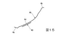
(第7変形例)
図15に示すように、第7変形例による補強部材4Gは、上述した実施の形態の補強部材4において、第1弾性連結板21、又は第2弾性連結板22のうちとくに大きな応力集中が生じる湾曲部にタイヤ周方向に重ねて配置されている。
なお、本変形例の補強部材4Gは、補強部材Aの本体部分4dの一部分にタイヤ周方向に重ね合わせて配置されているが、この位置に限定されることはなく両端部4a、4bに二重に配置することも可能である。
この場合には、射出成形時に補強部材4Gを適宜な位置に配置するだけですむため、連結部材15の応力集中箇所に限定した補強を簡単に行うことができる。
(Seventh Modification)
As shown in FIG. 15, the reinforcing
Note that the reinforcing
In this case, it is only necessary to arrange the reinforcing
(第8変形例)
図16に示すように、第8変形例による補強部材4Hは、上述した実施の形態の補強部材4において、第1弾性連結板21、又は第2弾性連結板22のうちとくに大きな応力集中が生じる湾曲部の厚さ寸法を厚くした膨出部46を形成した構成となっている。なお、本変形例の膨出部46は、補強部材Hの本体部分4dに設けられているが、この位置に限定されることはなく両端部4a、4bに設けることも可能である。
本第8変形例では、連結部材15の応力集中箇所に限定した補強を簡単に行うことができる。
(Eighth modification)
As shown in FIG. 16, the reinforcing
In the eighth modified example, the reinforcement limited to the stress concentration portion of the connecting
なお、本発明の技術範囲は、上記実施形態に限定されるものではなく、本発明の趣旨を逸脱しない範囲において、種々の変更を加えることが可能である。 The technical scope of the present invention is not limited to the above embodiment, and various modifications can be made without departing from the spirit of the present invention.
例えば、補強部材の形状、位置、数量等の構成は、本実施形態及び変形例に制限されることはなく、弾性連結板(第1弾性連結板21、又は第2弾性連結板22)のうち少なくとも湾曲部に埋設されていれば好ましいが、とくに限定されるものではない。
For example, the configuration of the shape, position, quantity, etc. of the reinforcing member is not limited to the present embodiment and the modified example, and the elastic connecting plate (the first elastic connecting
また、連結部材15は、複数の変曲部を有さない構成であってもかまわない。例えば外端部21a及び内端部21bから連結部材15の延在方向の中央部に向かうに従い横幅が漸次狭くなる形状とすることも可能である。
Moreover, the
また、本実施の形態では、連結部材15として第1弾性連結板21および第2弾性連結板22をそれぞれ1つずつ備えた構成を示したが、これに代えて、1つの連結部材15に第1弾性連結板21および第2弾性連結板22がそれぞれ複数ずつ、互いのタイヤ幅方向Hの位置を異ならせて備えられていてもよい。また、連結部材15を、外装体12とリング状体13との間にタイヤ幅方向Hに沿って複数設けてもよい。
Further, in the present embodiment, a configuration in which one each of the first elastic connecting
また、第1弾性連結板21および第2弾性連結板22の内端部21b、22bは、上述した実施の形態に代えて、例えば外装体12の外周面において軸線Oをタイヤ径方向で挟んで互いに反対となる各位置に各別に連結してもよいし、或いは、外装体12の外周面において、第1弾性連結板21および第2弾性連結板22の各外端部21a、22aにタイヤ径方向で対向する位置等に連結してもよい。また、本実施の形態に代えて、第1弾性連結板21および第2弾性連結板22の各外端部21a、22aを、リング状体13の内周面にタイヤ周方向位置を互いに異ならせて連結してもよい。
In addition, the
さらに、本実施の形態において、第1外装体25と第2外装体26との間にタイヤ幅方向Hの隙間を設けてもよく、或いは設けなくてもよい。また、外装体12及びリング状体13をタイヤ幅方向Hに3つ以上に分割してもよいし、分割しなくてもよい。
さらにまた、第1外装体25と第2外装体26とは、一体であってもよい。
Furthermore, in the present embodiment, a gap in the tire width direction H may or may not be provided between the first
Furthermore, the first
さらに、上記実施の形態では、外装体12、リング状体13、連結部材15を例えば射出成形により一体に形成したが、射出成形に限らず例えば鋳造等で一体に形成しても構わない。また、外装体12、リング状体13、連結部材15を個別に形成した後、これらを互いに連結してもよい。
さらに、上述した実施の形態では、外装体12を介して連結部材15を取り付け体11の外リング部18に間接的に連結する構成としたが、これに限定されるものではなく、例えば取り付け体11の外リング部18に連結部材15を直接的に連結する構成としても構わない。
Furthermore, in the above embodiment, the
Furthermore, in the above-described embodiment, the
その他、本発明の趣旨を逸脱しない範囲で、上記した実施形態における構成要素を周知の構成要素に置き換えることは適宜可能である。 In addition, the constituent elements in the above-described embodiments can be appropriately replaced with known constituent elements without departing from the gist of the present invention.
1 非空気入りタイヤ
4、4A〜4H 補強部材
4a、4b 端部
4d 本体部分
11 取り付け体
12 外装体
13 リング状体
15 連結部材
16 トレッド部材
18 外リング部
21 第1弾性連結板
21a 外端部
21b 内端部
22 第2弾性連結板
22a 外端部
22b 内端部
41 第1貫通孔
43 切欠き
44 第2貫通孔
45 多孔状貫通部(貫通孔)
O 軸線
H タイヤ幅方向
DESCRIPTION OF
O Axis line H Tire width direction
Claims (4)
前記取り付け体をタイヤ径方向の外側から囲繞するリング状体と、
前記取り付け体と前記リング状体とを変位自在に連結する連結部材と、
を備える非空気入りタイヤであって、
前記連結部材は、合成樹脂材料で形成されるとともに、前記連結部材に金属製の補強部材が埋設され、
前記補強部材は、前記連結部材の延在方向に沿った板状に形成され、前記連結部材全体に内在されていることを特徴とする非空気入りタイヤ。 An attachment attached to the axle;
A ring-shaped body surrounding the mounting body from the outside in the tire radial direction;
A connecting member that displaceably connects the attachment body and the ring-shaped body;
A non-pneumatic tire comprising
The connecting member is formed of a synthetic resin material, and a metal reinforcing member is embedded in the connecting member,
The reinforcing member, the formed coupling member extending direction in a plate shape was Tsu along the non-pneumatic tire characterized by being inherent in the whole the coupling member.
前記弾性連結板には、タイヤ周方向に湾曲する湾曲部が形成されており、
前記補強部材は、前記弾性連結板に埋設されていることを特徴とする請求項1に記載の非空気入りタイヤ。 The connecting member includes an elastic connecting plate whose both ends are separately connected to the attachment body and the ring-shaped body,
The elastic connecting plate is formed with a curved portion that curves in the tire circumferential direction,
The reinforcing member is a non-pneumatic tire according to claim 1, characterized in that is embedded in the elastic linking plates.
前記補強部材の端部は、前記取り付け体および前記リング状体のうち少なくとも一方の内部に達していることを特徴とする請求項1又は2に記載の非空気入りタイヤ。 Of the attachment body, at least a portion to which the connecting member is connected, the ring-shaped body, and the connecting member are integrally formed of a synthetic resin material,
The non-pneumatic tire according to claim 1 or 2, wherein an end of the reinforcing member reaches at least one of the attachment body and the ring-shaped body.
Priority Applications (5)
| Application Number | Priority Date | Filing Date | Title |
|---|---|---|---|
| JP2014226981A JP6619552B2 (en) | 2014-11-07 | 2014-11-07 | Non pneumatic tire |
| US15/521,670 US10399381B2 (en) | 2014-11-07 | 2015-10-01 | Non-pneumatic tire |
| PCT/JP2015/077932 WO2016072181A1 (en) | 2014-11-07 | 2015-10-01 | Non-pneumatic tire |
| CN201580058848.2A CN107148360A (en) | 2014-11-07 | 2015-10-01 | non-pneumatic tires |
| EP15857417.8A EP3216622A4 (en) | 2014-11-07 | 2015-10-01 | Non-pneumatic tire |
Applications Claiming Priority (1)
| Application Number | Priority Date | Filing Date | Title |
|---|---|---|---|
| JP2014226981A JP6619552B2 (en) | 2014-11-07 | 2014-11-07 | Non pneumatic tire |
Publications (2)
| Publication Number | Publication Date |
|---|---|
| JP2016088375A JP2016088375A (en) | 2016-05-23 |
| JP6619552B2 true JP6619552B2 (en) | 2019-12-11 |
Family
ID=55908910
Family Applications (1)
| Application Number | Title | Priority Date | Filing Date |
|---|---|---|---|
| JP2014226981A Active JP6619552B2 (en) | 2014-11-07 | 2014-11-07 | Non pneumatic tire |
Country Status (5)
| Country | Link |
|---|---|
| US (1) | US10399381B2 (en) |
| EP (1) | EP3216622A4 (en) |
| JP (1) | JP6619552B2 (en) |
| CN (1) | CN107148360A (en) |
| WO (1) | WO2016072181A1 (en) |
Families Citing this family (16)
| Publication number | Priority date | Publication date | Assignee | Title |
|---|---|---|---|---|
| EP3007909A4 (en) | 2013-06-15 | 2017-03-01 | Ronald Thompson | Annular ring and non-pneumatic tire |
| EP3253591B1 (en) | 2015-02-04 | 2021-06-30 | Camso Inc. | Non-pneumatic tire and other annular devices |
| JP6577824B2 (en) * | 2015-10-26 | 2019-09-18 | 住友ゴム工業株式会社 | Airless tire |
| WO2017072562A1 (en) * | 2015-10-30 | 2017-05-04 | Compagnie Generale Des Etablissements Michelin | Spoke fabrication for a non-pneumatic wheel |
| US11999419B2 (en) | 2015-12-16 | 2024-06-04 | Camso Inc. | Track system for traction of a vehicle |
| JP6772055B2 (en) * | 2016-12-27 | 2020-10-21 | Toyo Tire株式会社 | Non-pneumatic tires and their manufacturing methods |
| EP3638515B1 (en) | 2017-06-15 | 2023-04-05 | Camso Inc. | Wheel comprising a non-pneumatic tire |
| KR102005417B1 (en) * | 2017-09-11 | 2019-07-30 | 금호타이어 주식회사 | Rim for non pneumatic tire and wheel including the same |
| WO2019089008A1 (en) * | 2017-10-31 | 2019-05-09 | Compagnie Generale Des Etablissements Michelin | Non-pneumatic tire carcass |
| WO2019125459A1 (en) * | 2017-12-21 | 2019-06-27 | Compagnie Generale Des Etablissements Michelin | Curved reinforced resilient support for a non-pneumatic tire |
| WO2019125462A1 (en) * | 2017-12-21 | 2019-06-27 | Compagnie Generale Des Etablissements Michelin | Reinforced resilient support for a non-pneumatic tire |
| IT201800006956A1 (en) * | 2018-07-05 | 2020-01-05 | Freewheel assembly with front couplings for bicycles | |
| JP7321053B2 (en) * | 2019-10-17 | 2023-08-04 | Toyo Tire株式会社 | non-pneumatic tires |
| US12605966B2 (en) | 2020-12-18 | 2026-04-21 | Bridgestone Americas Tire Operations, Llc | Non-pneumatic tire with fiber metal laminate construction |
| FR3130201B1 (en) * | 2021-12-14 | 2024-07-26 | Michelin & Cie | Airless pneumatic with optimized shear band |
| CN119255921A (en) * | 2022-06-17 | 2025-01-03 | 普利司通美国轮胎运营有限责任公司 | Leaf spring support for spoke structure of non-pneumatic tire |
Family Cites Families (23)
| Publication number | Priority date | Publication date | Assignee | Title |
|---|---|---|---|---|
| FR463766A (en) * | 1913-09-23 | 1914-03-04 | Karl Bednar | Elastic tire for wheels |
| US4358162A (en) * | 1979-12-26 | 1982-11-09 | Unarco Industries, Inc. | Wheel having built-in hub |
| US5743316A (en) * | 1995-03-02 | 1998-04-28 | American Mobility Systems, Inc. | Dynamic steerable wheel spring |
| WO2003018332A1 (en) * | 2001-08-24 | 2003-03-06 | Societe De Technologie Michelin | Non-pneumatic tire |
| JP2004360803A (en) * | 2003-06-05 | 2004-12-24 | Honda Motor Co Ltd | Elastic support device |
| US7523773B2 (en) * | 2005-10-21 | 2009-04-28 | The Boeing Company | Non-pneumatic wheel |
| JP2008132951A (en) | 2006-11-29 | 2008-06-12 | Yokohama Rubber Co Ltd:The | Non-pneumatic tire |
| US8104524B2 (en) * | 2007-03-27 | 2012-01-31 | Resilient Technologies Llc | Tension-based non-pneumatic tire |
| CN101687432B (en) | 2007-06-29 | 2012-01-25 | 米其林研究和技术股份有限公司 | Elastic shear band with cylindrical elements and wheel including the shearing tape |
| WO2009016962A1 (en) * | 2007-07-31 | 2009-02-05 | Toyo Tire & Rubber Co., Ltd. | Non-pneumatic tire, and its manufacturing method |
| JP5436018B2 (en) * | 2008-07-09 | 2014-03-05 | 株式会社ブリヂストン | Non pneumatic tire |
| JP5401157B2 (en) * | 2008-10-27 | 2014-01-29 | 株式会社ブリヂストン | Non pneumatic tire |
| JP5624737B2 (en) * | 2009-07-22 | 2014-11-12 | 株式会社ブリヂストン | Non pneumatic tire |
| CN201506207U (en) * | 2009-09-28 | 2010-06-16 | 黎太生 | Combined spring vehicle-wheel with staggered-teeth |
| JP5394304B2 (en) * | 2010-04-12 | 2014-01-22 | 東洋ゴム工業株式会社 | Non-pneumatic tire and manufacturing method thereof |
| WO2012091754A1 (en) * | 2010-12-29 | 2012-07-05 | Michelin Recherche Et Technique, S.A. | Structurally supported non-pneumatic wheel with reinforcements and method of manufacture |
| JP5879089B2 (en) * | 2011-10-20 | 2016-03-08 | 株式会社ブリヂストン | Non-pneumatic tire manufacturing method |
| US20140062168A1 (en) * | 2012-08-30 | 2014-03-06 | Caterpillar Inc. | Non-pneumatic tire |
| JP6013899B2 (en) | 2012-12-19 | 2016-10-25 | 東洋ゴム工業株式会社 | Non-pneumatic tire |
| JP6043181B2 (en) * | 2012-12-26 | 2016-12-14 | 株式会社ブリヂストン | Non pneumatic tire |
| CN203078232U (en) * | 2013-01-17 | 2013-07-24 | 齐效荣 | Non-inflation reticular tire with steel structure in rubber structure |
| JP2014151739A (en) * | 2013-02-07 | 2014-08-25 | Yokohama Rubber Co Ltd:The | Pneumatic tire |
| KR101356326B1 (en) | 2013-02-28 | 2014-01-29 | 한국타이어 주식회사 | Non-pneumatic tire having reinforcing material of plate wire structure |
-
2014
- 2014-11-07 JP JP2014226981A patent/JP6619552B2/en active Active
-
2015
- 2015-10-01 EP EP15857417.8A patent/EP3216622A4/en not_active Withdrawn
- 2015-10-01 WO PCT/JP2015/077932 patent/WO2016072181A1/en not_active Ceased
- 2015-10-01 US US15/521,670 patent/US10399381B2/en active Active
- 2015-10-01 CN CN201580058848.2A patent/CN107148360A/en active Pending
Also Published As
| Publication number | Publication date |
|---|---|
| US10399381B2 (en) | 2019-09-03 |
| CN107148360A (en) | 2017-09-08 |
| WO2016072181A1 (en) | 2016-05-12 |
| US20170232787A1 (en) | 2017-08-17 |
| JP2016088375A (en) | 2016-05-23 |
| EP3216622A4 (en) | 2018-04-18 |
| EP3216622A1 (en) | 2017-09-13 |
Similar Documents
| Publication | Publication Date | Title |
|---|---|---|
| JP6619552B2 (en) | Non pneumatic tire | |
| JP6618693B2 (en) | Non pneumatic tire | |
| JP6152036B2 (en) | Non pneumatic tire | |
| JP5879089B2 (en) | Non-pneumatic tire manufacturing method | |
| JP6727136B2 (en) | Non-pneumatic tire | |
| JP6061625B2 (en) | Non pneumatic tire | |
| JP6534795B2 (en) | Non pneumatic tire | |
| JP2016113078A (en) | Non-pneumatic tire | |
| WO2016084512A1 (en) | Non-pneumatic tire | |
| WO2015198637A1 (en) | Non-pneumatic tire | |
| JP6358733B2 (en) | Non pneumatic tire | |
| JP6106428B2 (en) | Non pneumatic tire | |
| WO2015052987A1 (en) | Non-pneumatic tire | |
| WO2015072312A1 (en) | Non-pneumatic tire | |
| JP2015096371A (en) | Non pneumatic tire | |
| JP2016107751A (en) | Non-pneumatic tire | |
| JP6221114B2 (en) | Non pneumatic tire | |
| JP6591882B2 (en) | Non-pneumatic tire and method for producing non-pneumatic tire | |
| JP2014213789A (en) | Non-pneumatic tire | |
| JP6522936B2 (en) | Non pneumatic tire | |
| JP6522931B2 (en) | Non pneumatic tire | |
| JP6240972B2 (en) | Non pneumatic tire | |
| JP6240971B2 (en) | Non pneumatic tire | |
| JP2013163520A (en) | Non-pneumatic tire | |
| JP6591888B2 (en) | Non-pneumatic tire and method for producing non-pneumatic tire |
Legal Events
| Date | Code | Title | Description |
|---|---|---|---|
| A621 | Written request for application examination |
Free format text: JAPANESE INTERMEDIATE CODE: A621 Effective date: 20170623 |
|
| A131 | Notification of reasons for refusal |
Free format text: JAPANESE INTERMEDIATE CODE: A131 Effective date: 20180306 |
|
| A601 | Written request for extension of time |
Free format text: JAPANESE INTERMEDIATE CODE: A601 Effective date: 20180424 |
|
| A521 | Request for written amendment filed |
Free format text: JAPANESE INTERMEDIATE CODE: A523 Effective date: 20180612 |
|
| A02 | Decision of refusal |
Free format text: JAPANESE INTERMEDIATE CODE: A02 Effective date: 20180918 |
|
| A521 | Request for written amendment filed |
Free format text: JAPANESE INTERMEDIATE CODE: A523 Effective date: 20181218 |
|
| A911 | Transfer to examiner for re-examination before appeal (zenchi) |
Free format text: JAPANESE INTERMEDIATE CODE: A911 Effective date: 20181226 |
|
| A912 | Re-examination (zenchi) completed and case transferred to appeal board |
Free format text: JAPANESE INTERMEDIATE CODE: A912 Effective date: 20190125 |
|
| A61 | First payment of annual fees (during grant procedure) |
Free format text: JAPANESE INTERMEDIATE CODE: A61 Effective date: 20191115 |
|
| R150 | Certificate of patent or registration of utility model |
Ref document number: 6619552 Country of ref document: JP Free format text: JAPANESE INTERMEDIATE CODE: R150 |
|
| R250 | Receipt of annual fees |
Free format text: JAPANESE INTERMEDIATE CODE: R250 |
|
| R250 | Receipt of annual fees |
Free format text: JAPANESE INTERMEDIATE CODE: R250 |
|
| S531 | Written request for registration of change of domicile |
Free format text: JAPANESE INTERMEDIATE CODE: R313531 |
|
| S533 | Written request for registration of change of name |
Free format text: JAPANESE INTERMEDIATE CODE: R313533 |
|
| R360 | Written notification for declining of transfer of rights |
Free format text: JAPANESE INTERMEDIATE CODE: R360 |
|
| R250 | Receipt of annual fees |
Free format text: JAPANESE INTERMEDIATE CODE: R250 |
|
| R370 | Written measure of declining of transfer procedure |
Free format text: JAPANESE INTERMEDIATE CODE: R370 |
|
| R370 | Written measure of declining of transfer procedure |
Free format text: JAPANESE INTERMEDIATE CODE: R370 |
|
| R250 | Receipt of annual fees |
Free format text: JAPANESE INTERMEDIATE CODE: R250 |