JP6618479B2 - Skin formation of ceramic honeycomb body - Google Patents
Skin formation of ceramic honeycomb body Download PDFInfo
- Publication number
- JP6618479B2 JP6618479B2 JP2016557992A JP2016557992A JP6618479B2 JP 6618479 B2 JP6618479 B2 JP 6618479B2 JP 2016557992 A JP2016557992 A JP 2016557992A JP 2016557992 A JP2016557992 A JP 2016557992A JP 6618479 B2 JP6618479 B2 JP 6618479B2
- Authority
- JP
- Japan
- Prior art keywords
- sheet
- skin
- honeycomb
- honeycomb core
- cement
- Prior art date
- Legal status (The legal status is an assumption and is not a legal conclusion. Google has not performed a legal analysis and makes no representation as to the accuracy of the status listed.)
- Active
Links
- 239000000919 ceramic Substances 0.000 title description 20
- 230000015572 biosynthetic process Effects 0.000 title description 15
- 238000000034 method Methods 0.000 claims description 54
- 230000002093 peripheral effect Effects 0.000 claims description 25
- 210000004027 cell Anatomy 0.000 description 81
- 239000000203 mixture Substances 0.000 description 53
- 239000004568 cement Substances 0.000 description 52
- 239000011521 glass Substances 0.000 description 42
- 239000000945 filler Substances 0.000 description 41
- 239000000463 material Substances 0.000 description 41
- 239000000843 powder Substances 0.000 description 38
- 239000002245 particle Substances 0.000 description 28
- 239000011230 binding agent Substances 0.000 description 19
- 239000004744 fabric Substances 0.000 description 17
- 230000008569 process Effects 0.000 description 17
- 229910052799 carbon Inorganic materials 0.000 description 15
- VYPSYNLAJGMNEJ-UHFFFAOYSA-N Silicium dioxide Chemical compound O=[Si]=O VYPSYNLAJGMNEJ-UHFFFAOYSA-N 0.000 description 14
- 239000003981 vehicle Substances 0.000 description 14
- 238000001723 curing Methods 0.000 description 11
- 239000007788 liquid Substances 0.000 description 11
- 238000001035 drying Methods 0.000 description 9
- 238000010304 firing Methods 0.000 description 9
- PNEYBMLMFCGWSK-UHFFFAOYSA-N aluminium oxide Inorganic materials [O-2].[O-2].[O-2].[Al+3].[Al+3] PNEYBMLMFCGWSK-UHFFFAOYSA-N 0.000 description 8
- 238000001354 calcination Methods 0.000 description 8
- 238000004519 manufacturing process Methods 0.000 description 8
- 238000010438 heat treatment Methods 0.000 description 7
- 238000009826 distribution Methods 0.000 description 6
- 239000000835 fiber Substances 0.000 description 6
- 239000012784 inorganic fiber Substances 0.000 description 6
- 229910003480 inorganic solid Inorganic materials 0.000 description 6
- 239000000758 substrate Substances 0.000 description 6
- XLYOFNOQVPJJNP-UHFFFAOYSA-N water Substances O XLYOFNOQVPJJNP-UHFFFAOYSA-N 0.000 description 6
- 229910052878 cordierite Inorganic materials 0.000 description 5
- JSKIRARMQDRGJZ-UHFFFAOYSA-N dimagnesium dioxido-bis[(1-oxido-3-oxo-2,4,6,8,9-pentaoxa-1,3-disila-5,7-dialuminabicyclo[3.3.1]nonan-7-yl)oxy]silane Chemical compound [Mg++].[Mg++].[O-][Si]([O-])(O[Al]1O[Al]2O[Si](=O)O[Si]([O-])(O1)O2)O[Al]1O[Al]2O[Si](=O)O[Si]([O-])(O1)O2 JSKIRARMQDRGJZ-UHFFFAOYSA-N 0.000 description 5
- 239000003365 glass fiber Substances 0.000 description 5
- 239000002994 raw material Substances 0.000 description 5
- QTBSBXVTEAMEQO-UHFFFAOYSA-N Acetic acid Chemical compound CC(O)=O QTBSBXVTEAMEQO-UHFFFAOYSA-N 0.000 description 4
- 239000003054 catalyst Substances 0.000 description 4
- 229910010293 ceramic material Inorganic materials 0.000 description 4
- 239000008119 colloidal silica Substances 0.000 description 4
- 230000000052 comparative effect Effects 0.000 description 4
- 238000001125 extrusion Methods 0.000 description 4
- 238000011049 filling Methods 0.000 description 4
- 238000013035 low temperature curing Methods 0.000 description 4
- 239000011368 organic material Substances 0.000 description 4
- -1 polyethylene Polymers 0.000 description 4
- 238000012545 processing Methods 0.000 description 4
- 239000002759 woven fabric Substances 0.000 description 4
- HEMHJVSKTPXQMS-UHFFFAOYSA-M Sodium hydroxide Chemical compound [OH-].[Na+] HEMHJVSKTPXQMS-UHFFFAOYSA-M 0.000 description 3
- 239000000654 additive Substances 0.000 description 3
- 230000002902 bimodal effect Effects 0.000 description 3
- KRKNYBCHXYNGOX-UHFFFAOYSA-N citric acid Chemical compound OC(=O)CC(O)(C(O)=O)CC(O)=O KRKNYBCHXYNGOX-UHFFFAOYSA-N 0.000 description 3
- 230000009977 dual effect Effects 0.000 description 3
- 238000009472 formulation Methods 0.000 description 3
- 239000005350 fused silica glass Substances 0.000 description 3
- 238000005259 measurement Methods 0.000 description 3
- 238000012986 modification Methods 0.000 description 3
- 230000004048 modification Effects 0.000 description 3
- 229920001778 nylon Polymers 0.000 description 3
- 239000011148 porous material Substances 0.000 description 3
- 230000002787 reinforcement Effects 0.000 description 3
- 239000000377 silicon dioxide Substances 0.000 description 3
- 239000007787 solid Substances 0.000 description 3
- 239000002904 solvent Substances 0.000 description 3
- 229910000505 Al2TiO5 Inorganic materials 0.000 description 2
- 229920000742 Cotton Polymers 0.000 description 2
- VEXZGXHMUGYJMC-UHFFFAOYSA-N Hydrochloric acid Chemical compound Cl VEXZGXHMUGYJMC-UHFFFAOYSA-N 0.000 description 2
- 229920003091 Methocel™ Polymers 0.000 description 2
- UFWIBTONFRDIAS-UHFFFAOYSA-N Naphthalene Chemical compound C1=CC=CC2=CC=CC=C21 UFWIBTONFRDIAS-UHFFFAOYSA-N 0.000 description 2
- QAOWNCQODCNURD-UHFFFAOYSA-N Sulfuric acid Chemical compound OS(O)(=O)=O QAOWNCQODCNURD-UHFFFAOYSA-N 0.000 description 2
- GSEJCLTVZPLZKY-UHFFFAOYSA-N Triethanolamine Chemical compound OCCN(CCO)CCO GSEJCLTVZPLZKY-UHFFFAOYSA-N 0.000 description 2
- 230000000996 additive effect Effects 0.000 description 2
- 239000012298 atmosphere Substances 0.000 description 2
- 238000005266 casting Methods 0.000 description 2
- 238000004320 controlled atmosphere Methods 0.000 description 2
- 238000005520 cutting process Methods 0.000 description 2
- KZHJGOXRZJKJNY-UHFFFAOYSA-N dioxosilane;oxo(oxoalumanyloxy)alumane Chemical compound O=[Si]=O.O=[Si]=O.O=[Al]O[Al]=O.O=[Al]O[Al]=O.O=[Al]O[Al]=O KZHJGOXRZJKJNY-UHFFFAOYSA-N 0.000 description 2
- 238000005553 drilling Methods 0.000 description 2
- 230000009969 flowable effect Effects 0.000 description 2
- 239000012530 fluid Substances 0.000 description 2
- 238000000227 grinding Methods 0.000 description 2
- 239000011256 inorganic filler Substances 0.000 description 2
- 229910003475 inorganic filler Inorganic materials 0.000 description 2
- 229910052500 inorganic mineral Inorganic materials 0.000 description 2
- 229920000609 methyl cellulose Polymers 0.000 description 2
- 239000001923 methylcellulose Substances 0.000 description 2
- 235000010981 methylcellulose Nutrition 0.000 description 2
- 239000011707 mineral Substances 0.000 description 2
- 229910052863 mullite Inorganic materials 0.000 description 2
- 239000004745 nonwoven fabric Substances 0.000 description 2
- 239000012466 permeate Substances 0.000 description 2
- 230000000704 physical effect Effects 0.000 description 2
- 229920000728 polyester Polymers 0.000 description 2
- AABBHSMFGKYLKE-SNAWJCMRSA-N propan-2-yl (e)-but-2-enoate Chemical compound C\C=C\C(=O)OC(C)C AABBHSMFGKYLKE-SNAWJCMRSA-N 0.000 description 2
- 239000012779 reinforcing material Substances 0.000 description 2
- 239000002002 slurry Substances 0.000 description 2
- 239000004071 soot Substances 0.000 description 2
- 239000000126 substance Substances 0.000 description 2
- 238000004804 winding Methods 0.000 description 2
- VHUUQVKOLVNVRT-UHFFFAOYSA-N Ammonium hydroxide Chemical compound [NH4+].[OH-] VHUUQVKOLVNVRT-UHFFFAOYSA-N 0.000 description 1
- 244000025254 Cannabis sativa Species 0.000 description 1
- 235000012766 Cannabis sativa ssp. sativa var. sativa Nutrition 0.000 description 1
- 235000012765 Cannabis sativa ssp. sativa var. spontanea Nutrition 0.000 description 1
- OKTJSMMVPCPJKN-UHFFFAOYSA-N Carbon Chemical compound [C] OKTJSMMVPCPJKN-UHFFFAOYSA-N 0.000 description 1
- 229920000049 Carbon (fiber) Polymers 0.000 description 1
- 229920003043 Cellulose fiber Polymers 0.000 description 1
- LCGLNKUTAGEVQW-UHFFFAOYSA-N Dimethyl ether Chemical group COC LCGLNKUTAGEVQW-UHFFFAOYSA-N 0.000 description 1
- 239000001856 Ethyl cellulose Substances 0.000 description 1
- ZZSNKZQZMQGXPY-UHFFFAOYSA-N Ethyl cellulose Chemical compound CCOCC1OC(OC)C(OCC)C(OCC)C1OC1C(O)C(O)C(OC)C(CO)O1 ZZSNKZQZMQGXPY-UHFFFAOYSA-N 0.000 description 1
- GRYLNZFGIOXLOG-UHFFFAOYSA-N Nitric acid Chemical compound O[N+]([O-])=O GRYLNZFGIOXLOG-UHFFFAOYSA-N 0.000 description 1
- 229920003171 Poly (ethylene oxide) Polymers 0.000 description 1
- 239000004698 Polyethylene Substances 0.000 description 1
- 239000004372 Polyvinyl alcohol Substances 0.000 description 1
- 229910052581 Si3N4 Inorganic materials 0.000 description 1
- 229910004298 SiO 2 Inorganic materials 0.000 description 1
- 239000002318 adhesion promoter Substances 0.000 description 1
- 239000000853 adhesive Substances 0.000 description 1
- 230000001070 adhesive effect Effects 0.000 description 1
- 230000002411 adverse Effects 0.000 description 1
- 230000032683 aging Effects 0.000 description 1
- 229910000323 aluminium silicate Inorganic materials 0.000 description 1
- 239000000908 ammonium hydroxide Substances 0.000 description 1
- 230000003466 anti-cipated effect Effects 0.000 description 1
- 230000004888 barrier function Effects 0.000 description 1
- 230000008901 benefit Effects 0.000 description 1
- 239000006227 byproduct Substances 0.000 description 1
- 235000009120 camo Nutrition 0.000 description 1
- 238000009924 canning Methods 0.000 description 1
- 239000004917 carbon fiber Substances 0.000 description 1
- 239000000969 carrier Substances 0.000 description 1
- 230000015556 catabolic process Effects 0.000 description 1
- 230000003197 catalytic effect Effects 0.000 description 1
- 238000006555 catalytic reaction Methods 0.000 description 1
- 210000002421 cell wall Anatomy 0.000 description 1
- 229920003086 cellulose ether Polymers 0.000 description 1
- 238000009750 centrifugal casting Methods 0.000 description 1
- 235000005607 chanvre indien Nutrition 0.000 description 1
- 239000011248 coating agent Substances 0.000 description 1
- 238000000576 coating method Methods 0.000 description 1
- 238000002485 combustion reaction Methods 0.000 description 1
- 239000012141 concentrate Substances 0.000 description 1
- 239000000470 constituent Substances 0.000 description 1
- 230000007547 defect Effects 0.000 description 1
- 238000007872 degassing Methods 0.000 description 1
- 238000006731 degradation reaction Methods 0.000 description 1
- 239000008367 deionised water Substances 0.000 description 1
- 229910021641 deionized water Inorganic materials 0.000 description 1
- HNPSIPDUKPIQMN-UHFFFAOYSA-N dioxosilane;oxo(oxoalumanyloxy)alumane Chemical compound O=[Si]=O.O=[Al]O[Al]=O HNPSIPDUKPIQMN-UHFFFAOYSA-N 0.000 description 1
- 230000007613 environmental effect Effects 0.000 description 1
- 229920001249 ethyl cellulose Polymers 0.000 description 1
- 235000019325 ethyl cellulose Nutrition 0.000 description 1
- 230000009970 fire resistant effect Effects 0.000 description 1
- 239000003349 gelling agent Substances 0.000 description 1
- 239000011487 hemp Substances 0.000 description 1
- 238000007602 hot air drying Methods 0.000 description 1
- 239000004615 ingredient Substances 0.000 description 1
- 238000002347 injection Methods 0.000 description 1
- 239000007924 injection Substances 0.000 description 1
- 238000001746 injection moulding Methods 0.000 description 1
- 239000011147 inorganic material Substances 0.000 description 1
- 239000004816 latex Substances 0.000 description 1
- 229920000126 latex Polymers 0.000 description 1
- 238000003754 machining Methods 0.000 description 1
- 238000012423 maintenance Methods 0.000 description 1
- VNWKTOKETHGBQD-UHFFFAOYSA-N methane Chemical compound C VNWKTOKETHGBQD-UHFFFAOYSA-N 0.000 description 1
- 238000002156 mixing Methods 0.000 description 1
- 239000003607 modifier Substances 0.000 description 1
- 238000000465 moulding Methods 0.000 description 1
- 229910017604 nitric acid Inorganic materials 0.000 description 1
- 230000003287 optical effect Effects 0.000 description 1
- 235000011837 pasties Nutrition 0.000 description 1
- 238000005498 polishing Methods 0.000 description 1
- 229920000573 polyethylene Polymers 0.000 description 1
- 229920000642 polymer Polymers 0.000 description 1
- 229920005596 polymer binder Polymers 0.000 description 1
- 239000002491 polymer binding agent Substances 0.000 description 1
- 229920002451 polyvinyl alcohol Polymers 0.000 description 1
- 235000019422 polyvinyl alcohol Nutrition 0.000 description 1
- 238000012805 post-processing Methods 0.000 description 1
- 230000005855 radiation Effects 0.000 description 1
- 239000011819 refractory material Substances 0.000 description 1
- 238000007789 sealing Methods 0.000 description 1
- 230000035939 shock Effects 0.000 description 1
- HBMJWWWQQXIZIP-UHFFFAOYSA-N silicon carbide Chemical compound [Si+]#[C-] HBMJWWWQQXIZIP-UHFFFAOYSA-N 0.000 description 1
- 229910010271 silicon carbide Inorganic materials 0.000 description 1
- HQVNEWCFYHHQES-UHFFFAOYSA-N silicon nitride Chemical compound N12[Si]34N5[Si]62N3[Si]51N64 HQVNEWCFYHHQES-UHFFFAOYSA-N 0.000 description 1
- 239000011343 solid material Substances 0.000 description 1
- 238000009718 spray deposition Methods 0.000 description 1
- 239000007858 starting material Substances 0.000 description 1
- 239000000375 suspending agent Substances 0.000 description 1
- 229920002994 synthetic fiber Polymers 0.000 description 1
- 238000009966 trimming Methods 0.000 description 1
- 238000009736 wetting Methods 0.000 description 1
- 239000000230 xanthan gum Substances 0.000 description 1
- 229920001285 xanthan gum Polymers 0.000 description 1
- 229940082509 xanthan gum Drugs 0.000 description 1
- 235000010493 xanthan gum Nutrition 0.000 description 1
Images


Classifications
-
- C—CHEMISTRY; METALLURGY
- C04—CEMENTS; CONCRETE; ARTIFICIAL STONE; CERAMICS; REFRACTORIES
- C04B—LIME, MAGNESIA; SLAG; CEMENTS; COMPOSITIONS THEREOF, e.g. MORTARS, CONCRETE OR LIKE BUILDING MATERIALS; ARTIFICIAL STONE; CERAMICS; REFRACTORIES; TREATMENT OF NATURAL STONE
- C04B38/00—Porous mortars, concrete, artificial stone or ceramic ware; Preparation thereof
- C04B38/0006—Honeycomb structures
-
- B—PERFORMING OPERATIONS; TRANSPORTING
- B01—PHYSICAL OR CHEMICAL PROCESSES OR APPARATUS IN GENERAL
- B01D—SEPARATION
- B01D46/00—Filters or filtering processes specially modified for separating dispersed particles from gases or vapours
- B01D46/0001—Making filtering elements
-
- B—PERFORMING OPERATIONS; TRANSPORTING
- B01—PHYSICAL OR CHEMICAL PROCESSES OR APPARATUS IN GENERAL
- B01D—SEPARATION
- B01D46/00—Filters or filtering processes specially modified for separating dispersed particles from gases or vapours
- B01D46/24—Particle separators, e.g. dust precipitators, using rigid hollow filter bodies
- B01D46/2403—Particle separators, e.g. dust precipitators, using rigid hollow filter bodies characterised by the physical shape or structure of the filtering element
- B01D46/2418—Honeycomb filters
- B01D46/2425—Honeycomb filters characterized by parameters related to the physical properties of the honeycomb structure material
- B01D46/2444—Honeycomb filters characterized by parameters related to the physical properties of the honeycomb structure material of the outer peripheral sealing
-
- B—PERFORMING OPERATIONS; TRANSPORTING
- B28—WORKING CEMENT, CLAY, OR STONE
- B28B—SHAPING CLAY OR OTHER CERAMIC COMPOSITIONS; SHAPING SLAG; SHAPING MIXTURES CONTAINING CEMENTITIOUS MATERIAL, e.g. PLASTER
- B28B19/00—Machines or methods for applying the material to surfaces to form a permanent layer thereon
- B28B19/0038—Machines or methods for applying the material to surfaces to form a permanent layer thereon lining the outer wall of hollow objects, e.g. pipes
-
- C—CHEMISTRY; METALLURGY
- C04—CEMENTS; CONCRETE; ARTIFICIAL STONE; CERAMICS; REFRACTORIES
- C04B—LIME, MAGNESIA; SLAG; CEMENTS; COMPOSITIONS THEREOF, e.g. MORTARS, CONCRETE OR LIKE BUILDING MATERIALS; ARTIFICIAL STONE; CERAMICS; REFRACTORIES; TREATMENT OF NATURAL STONE
- C04B28/00—Compositions of mortars, concrete or artificial stone, containing inorganic binders or the reaction product of an inorganic and an organic binder, e.g. polycarboxylate cements
- C04B28/24—Compositions of mortars, concrete or artificial stone, containing inorganic binders or the reaction product of an inorganic and an organic binder, e.g. polycarboxylate cements containing alkyl, ammonium or metal silicates; containing silica sols
-
- C—CHEMISTRY; METALLURGY
- C04—CEMENTS; CONCRETE; ARTIFICIAL STONE; CERAMICS; REFRACTORIES
- C04B—LIME, MAGNESIA; SLAG; CEMENTS; COMPOSITIONS THEREOF, e.g. MORTARS, CONCRETE OR LIKE BUILDING MATERIALS; ARTIFICIAL STONE; CERAMICS; REFRACTORIES; TREATMENT OF NATURAL STONE
- C04B35/00—Shaped ceramic products characterised by their composition; Ceramics compositions; Processing powders of inorganic compounds preparatory to the manufacturing of ceramic products
- C04B35/01—Shaped ceramic products characterised by their composition; Ceramics compositions; Processing powders of inorganic compounds preparatory to the manufacturing of ceramic products based on oxide ceramics
- C04B35/16—Shaped ceramic products characterised by their composition; Ceramics compositions; Processing powders of inorganic compounds preparatory to the manufacturing of ceramic products based on oxide ceramics based on silicates other than clay
- C04B35/18—Shaped ceramic products characterised by their composition; Ceramics compositions; Processing powders of inorganic compounds preparatory to the manufacturing of ceramic products based on oxide ceramics based on silicates other than clay rich in aluminium oxide
- C04B35/195—Alkaline earth aluminosilicates, e.g. cordierite or anorthite
-
- C—CHEMISTRY; METALLURGY
- C04—CEMENTS; CONCRETE; ARTIFICIAL STONE; CERAMICS; REFRACTORIES
- C04B—LIME, MAGNESIA; SLAG; CEMENTS; COMPOSITIONS THEREOF, e.g. MORTARS, CONCRETE OR LIKE BUILDING MATERIALS; ARTIFICIAL STONE; CERAMICS; REFRACTORIES; TREATMENT OF NATURAL STONE
- C04B41/00—After-treatment of mortars, concrete, artificial stone or ceramics; Treatment of natural stone
- C04B41/009—After-treatment of mortars, concrete, artificial stone or ceramics; Treatment of natural stone characterised by the material treated
-
- C—CHEMISTRY; METALLURGY
- C04—CEMENTS; CONCRETE; ARTIFICIAL STONE; CERAMICS; REFRACTORIES
- C04B—LIME, MAGNESIA; SLAG; CEMENTS; COMPOSITIONS THEREOF, e.g. MORTARS, CONCRETE OR LIKE BUILDING MATERIALS; ARTIFICIAL STONE; CERAMICS; REFRACTORIES; TREATMENT OF NATURAL STONE
- C04B41/00—After-treatment of mortars, concrete, artificial stone or ceramics; Treatment of natural stone
- C04B41/45—Coating or impregnating, e.g. injection in masonry, partial coating of green or fired ceramics, organic coating compositions for adhering together two concrete elements
- C04B41/4505—Coating or impregnating, e.g. injection in masonry, partial coating of green or fired ceramics, organic coating compositions for adhering together two concrete elements characterised by the method of application
- C04B41/4535—Coating or impregnating, e.g. injection in masonry, partial coating of green or fired ceramics, organic coating compositions for adhering together two concrete elements characterised by the method of application applied as a solution, emulsion, dispersion or suspension
-
- C—CHEMISTRY; METALLURGY
- C04—CEMENTS; CONCRETE; ARTIFICIAL STONE; CERAMICS; REFRACTORIES
- C04B—LIME, MAGNESIA; SLAG; CEMENTS; COMPOSITIONS THEREOF, e.g. MORTARS, CONCRETE OR LIKE BUILDING MATERIALS; ARTIFICIAL STONE; CERAMICS; REFRACTORIES; TREATMENT OF NATURAL STONE
- C04B41/00—After-treatment of mortars, concrete, artificial stone or ceramics; Treatment of natural stone
- C04B41/45—Coating or impregnating, e.g. injection in masonry, partial coating of green or fired ceramics, organic coating compositions for adhering together two concrete elements
- C04B41/50—Coating or impregnating, e.g. injection in masonry, partial coating of green or fired ceramics, organic coating compositions for adhering together two concrete elements with inorganic materials
- C04B41/5076—Coating or impregnating, e.g. injection in masonry, partial coating of green or fired ceramics, organic coating compositions for adhering together two concrete elements with inorganic materials with masses bonded by inorganic cements
- C04B41/5089—Silica sols, alkyl, ammonium or alkali metal silicate cements
-
- C—CHEMISTRY; METALLURGY
- C04—CEMENTS; CONCRETE; ARTIFICIAL STONE; CERAMICS; REFRACTORIES
- C04B—LIME, MAGNESIA; SLAG; CEMENTS; COMPOSITIONS THEREOF, e.g. MORTARS, CONCRETE OR LIKE BUILDING MATERIALS; ARTIFICIAL STONE; CERAMICS; REFRACTORIES; TREATMENT OF NATURAL STONE
- C04B41/00—After-treatment of mortars, concrete, artificial stone or ceramics; Treatment of natural stone
- C04B41/80—After-treatment of mortars, concrete, artificial stone or ceramics; Treatment of natural stone of only ceramics
- C04B41/81—Coating or impregnation
- C04B41/85—Coating or impregnation with inorganic materials
-
- C—CHEMISTRY; METALLURGY
- C04—CEMENTS; CONCRETE; ARTIFICIAL STONE; CERAMICS; REFRACTORIES
- C04B—LIME, MAGNESIA; SLAG; CEMENTS; COMPOSITIONS THEREOF, e.g. MORTARS, CONCRETE OR LIKE BUILDING MATERIALS; ARTIFICIAL STONE; CERAMICS; REFRACTORIES; TREATMENT OF NATURAL STONE
- C04B41/00—After-treatment of mortars, concrete, artificial stone or ceramics; Treatment of natural stone
- C04B41/80—After-treatment of mortars, concrete, artificial stone or ceramics; Treatment of natural stone of only ceramics
- C04B41/81—Coating or impregnation
- C04B41/89—Coating or impregnation for obtaining at least two superposed coatings having different compositions
-
- C—CHEMISTRY; METALLURGY
- C04—CEMENTS; CONCRETE; ARTIFICIAL STONE; CERAMICS; REFRACTORIES
- C04B—LIME, MAGNESIA; SLAG; CEMENTS; COMPOSITIONS THEREOF, e.g. MORTARS, CONCRETE OR LIKE BUILDING MATERIALS; ARTIFICIAL STONE; CERAMICS; REFRACTORIES; TREATMENT OF NATURAL STONE
- C04B2111/00—Mortars, concrete or artificial stone or mixtures to prepare them, characterised by specific function, property or use
- C04B2111/00474—Uses not provided for elsewhere in C04B2111/00
- C04B2111/00793—Uses not provided for elsewhere in C04B2111/00 as filters or diaphragms
-
- C—CHEMISTRY; METALLURGY
- C04—CEMENTS; CONCRETE; ARTIFICIAL STONE; CERAMICS; REFRACTORIES
- C04B—LIME, MAGNESIA; SLAG; CEMENTS; COMPOSITIONS THEREOF, e.g. MORTARS, CONCRETE OR LIKE BUILDING MATERIALS; ARTIFICIAL STONE; CERAMICS; REFRACTORIES; TREATMENT OF NATURAL STONE
- C04B2111/00—Mortars, concrete or artificial stone or mixtures to prepare them, characterised by specific function, property or use
- C04B2111/00474—Uses not provided for elsewhere in C04B2111/00
- C04B2111/0081—Uses not provided for elsewhere in C04B2111/00 as catalysts or catalyst carriers
-
- Y—GENERAL TAGGING OF NEW TECHNOLOGICAL DEVELOPMENTS; GENERAL TAGGING OF CROSS-SECTIONAL TECHNOLOGIES SPANNING OVER SEVERAL SECTIONS OF THE IPC; TECHNICAL SUBJECTS COVERED BY FORMER USPC CROSS-REFERENCE ART COLLECTIONS [XRACs] AND DIGESTS
- Y10—TECHNICAL SUBJECTS COVERED BY FORMER USPC
- Y10T—TECHNICAL SUBJECTS COVERED BY FORMER US CLASSIFICATION
- Y10T428/00—Stock material or miscellaneous articles
- Y10T428/24—Structurally defined web or sheet [e.g., overall dimension, etc.]
- Y10T428/24149—Honeycomb-like
Landscapes
- Chemical & Material Sciences (AREA)
- Engineering & Computer Science (AREA)
- Ceramic Engineering (AREA)
- Structural Engineering (AREA)
- Organic Chemistry (AREA)
- Materials Engineering (AREA)
- Inorganic Chemistry (AREA)
- Chemical Kinetics & Catalysis (AREA)
- Manufacturing & Machinery (AREA)
- Geometry (AREA)
- Physics & Mathematics (AREA)
- Mechanical Engineering (AREA)
- Dispersion Chemistry (AREA)
- Civil Engineering (AREA)
- Filtering Materials (AREA)
- Porous Artificial Stone Or Porous Ceramic Products (AREA)
- Devices For Post-Treatments, Processing, Supply, Discharge, And Other Processes (AREA)
- Press-Shaping Or Shaping Using Conveyers (AREA)
- Producing Shaped Articles From Materials (AREA)
- Catalysts (AREA)
- Laminated Bodies (AREA)
Description
本出願は、その内容がその全体を参照することにより本書に組み込まれる、2014年3月18日に出願された米国特許出願第14/217,629号の優先権の利益を主張するものである。 This application claims the benefit of priority of US patent application Ser. No. 14 / 217,629 filed Mar. 18, 2014, the contents of which are hereby incorporated by reference in its entirety. .
本開示の例示的な実施形態は、ハニカム本体の外皮形成に関し、より具体的には、開口している部分セルを周縁に有する外皮形成されたハニカム本体と、これを製造する方法に関する。 Exemplary embodiments of the present disclosure relate to honeycomb body skin formation, and more specifically to a skin-formed honeycomb body having open partial cells at the periphery and a method of manufacturing the same.
内燃機関からの排ガスの後処理では、高表面積基材に担持された触媒を使用することがあり、またディーゼルエンジンおよびいくつかのガソリン直噴エンジンの場合には、炭素煤粒子の除去のために触媒フィルタが使用され得る。これらの用途におけるフィルタおよび触媒担体は、耐火性、耐熱衝撃性のもの、pO2条件範囲下で安定しているもの、触媒システムで非反応性のものでもよく、また排ガス流に対し小さい抵抗を示すものでもよい。多孔質セラミックのフロースルーハニカム基材およびウォールフローハニカムフィルタ(本書で一般にハニカム本体と称す)が、これらの用途で使用され得る。 In the aftertreatment of exhaust gas from internal combustion engines, catalysts supported on high surface area substrates may be used, and in the case of diesel engines and some gasoline direct injection engines, for the removal of carbon soot particles A catalytic filter may be used. Filters and catalyst carriers in these applications may be fire resistant, thermal shock resistant, stable under pO 2 conditions, non-reactive in catalyst systems, and have low resistance to exhaust gas flow. It may be shown. Porous ceramic flow-through honeycomb substrates and wall flow honeycomb filters (commonly referred to herein as honeycomb bodies) may be used in these applications.
粒子フィルタおよび基材を、相手先ブランド製造会社(OEM)およびサプライチェーンにより設定される外形寸法要件に合わせて製造することは、製造中の乾燥および焼成による収縮に起因して困難になり得る。結果として、既に所望の寸法に機械加工すなわち「輪郭形成」されたハニカム本体の外皮を形成するために、セラミックセメントが使用され得る。本書では「ハニカム本体」という用語は、単一のハニカムモノリスと、モノリスを形成するためにセラミックセメントを用いることなどにより複数のハニカムセグメントを一緒に固定して形成された、ハニカム本体とを含む。セラミックセメントを混合し、焼成されて輪郭形成または分割された、ハニカム本体に塗布してもよく、さらに湿った外皮を乾燥させてもよい。セラミックセメントをハニカム本体の外側に塗布する作業またはプロセスを、本書ではハニカム本体の「外皮形成」と称する。外皮がその上に配置されているハニカム本体を、本書では「外皮形成された」ハニカム本体と称する。本書で開示されるように輪郭形成は、所望の寸法への研削、機械加工、切断、穿孔、コア穿孔などを称する。 Manufacturing particle filters and substrates to meet the dimensional requirements set by original equipment manufacturers (OEMs) and supply chains can be difficult due to drying and firing shrinkage during manufacturing. As a result, ceramic cement can be used to form the outer shell of the honeycomb body that has already been machined or “contoured” to the desired dimensions. As used herein, the term “honeycomb body” includes a single honeycomb monolith and a honeycomb body formed by securing a plurality of honeycomb segments together, such as by using ceramic cement to form the monolith. Ceramic cement may be mixed and fired to be applied to the contoured or segmented honeycomb body, and the wet skin may be dried. The operation or process of applying ceramic cement to the outside of the honeycomb body is referred to herein as “shell formation” of the honeycomb body. A honeycomb body with a skin disposed thereon is referred to herein as a “shelled” honeycomb body. Contouring as disclosed herein refers to grinding to desired dimensions, machining, cutting, drilling, core drilling, and the like.
この背景技術の項で開示される上記の情報は、単に本開示の背景の理解を高めるためのものであり、従って従来技術のいずれの部分も形成しない情報、または従来技術が通常の当業者に示唆し得ないものも含み得る。 The above information disclosed in this Background section is merely to enhance understanding of the background of the present disclosure, and thus information that does not form any part of the prior art, or is known to those of ordinary skill in the art. It can also include things that cannot be suggested.
本開示の例示的な実施形態は、入口面から出口面まで延在している開口した部分チャネルを外周部分に有する、外皮形成されたハニカム本体を提供する。 An exemplary embodiment of the present disclosure provides a skinned honeycomb body having an open partial channel at the outer peripheral portion that extends from the inlet surface to the outlet surface.
本開示の例示的な実施形態は、入口面から出口面まで延在している開口した部分セルチャネルを外周部分に有する、外皮形成されたハニカム本体を製造する方法をさらに提供する。 Exemplary embodiments of the present disclosure further provide a method of manufacturing a skinned honeycomb body having an open partial cell channel extending from an inlet surface to an outlet surface at an outer peripheral portion.
本開示のさらなる特徴は以下の説明に明記され、一部はその説明から明らかであろうし、あるいは本開示を実施することにより理解されるであろう。 Additional features of the disclosure will be set forth in the description which follows, and in part will be obvious from the description, or may be learned by practice of the disclosure.
例示的な実施形態は、ハニカム本体を開示する。この本体はハニカムコアを含み、ハニカムコアは、入口面から出口面まで延在し入口面と出口面との間にセルチャネルを画成する、複数のチャネル壁と、入口面から出口面まで延在する外周と、ハニカムコアのこの外周に隣接した部分セルチャネルとを含み、部分セルチャネルの夫々のチャネル壁は、ハニカムコアの外周の位置に間隙を有し、さらに部分セルチャネルの夫々は、入口面から出口面まで、チャネル壁とハニカムコアの外周に位置する間隙とにより囲まれた容積を有している。このセラミック物品は、部分セルチャネルの全容積の大部分が入口面から出口面まで開口するように間隙にわたってハニカムコアの外周上に配置された、外皮を備えている。 An exemplary embodiment discloses a honeycomb body. The body includes a honeycomb core, the honeycomb core extending from the inlet face to the outlet face and defining a cell channel between the inlet face and the outlet face, and extending from the inlet face to the outlet face. Each outer peripheral wall and a partial cell channel adjacent to the outer periphery of the honeycomb core, each channel wall of the partial cell channel has a gap at the outer peripheral position of the honeycomb core, and each of the partial cell channels, From the inlet surface to the outlet surface, it has a volume surrounded by a channel wall and a gap located on the outer periphery of the honeycomb core. The ceramic article includes a skin disposed on the outer periphery of the honeycomb core across the gap so that a majority of the total volume of the partial cell channel opens from the inlet face to the outlet face.
例示的な実施形態は、ハニカム本体を製造する方法をさらに開示する。この方法は、ハニカムコアの第1の端面から第2の端面まで延在するハニカムコアの外周表面上に、シートを配置するステップと、シート上に外皮バッチを配置するステップと、外皮バッチを硬化させるステップであって、硬化した外皮をハニカムコアに接合させて、ハニカム本体を形成するステップとを含む。この方法において、硬化させるステップはシートの少なくとも一部分を犠牲にするステップを含み、硬化した外皮は、第1の端面から第2の端面まで開口した、周縁の部分セルチャネルの部分の外壁を形成する。 Exemplary embodiments further disclose a method of manufacturing a honeycomb body. The method includes the steps of: placing a sheet on the outer peripheral surface of the honeycomb core extending from the first end face to the second end face of the honeycomb core; placing the skin batch on the sheet; and curing the skin batch. Forming a honeycomb body by bonding the cured skin to the honeycomb core. In this method, the curing step includes sacrificing at least a portion of the sheet, and the cured skin forms an outer wall of a portion of the peripheral partial cell channel that is open from the first end surface to the second end surface. .
前述の一般的な説明および以下の詳細な説明は例示および説明のためのものであり、本開示のさらなる説明を提供するよう意図されたものであることを理解されたい。 It should be understood that the foregoing general description and the following detailed description are exemplary and explanatory and are intended to provide further explanation of the present disclosure.
本開示のさらなる理解を提供するために含まれ、本明細書に組み込まれかつその一部を構成する添付の図面は、本開示の例示的な実施形態を示したものであり、その説明と共に本開示の原理の説明に役立つ。 The accompanying drawings, which are included to provide a further understanding of the disclosure, and are incorporated in and constitute a part of this specification, illustrate exemplary embodiments of the disclosure, and together with the description, Helps explain the principles of the disclosure.
本開示の例示的な実施形態を示している添付の図面を参照して、本開示を以下でより十分に説明する。ただし、本開示は多くの異なる形で具現化され得るものであり、本書に明記される例示的な実施形態に限定されると解釈されるべきではない。むしろこれらの実施形態は、本開示が徹底したものとなるように提供され、本開示の範囲を当業者に十分に伝えるであろう。図面において、層および領域のサイズおよび相対的サイズは、明瞭にするため誇張されていることがある。 The present disclosure will be described more fully hereinafter with reference to the accompanying drawings, which illustrate exemplary embodiments of the present disclosure. However, the present disclosure may be embodied in many different forms and should not be construed as limited to the exemplary embodiments set forth herein. Rather, these embodiments are provided so that this disclosure will be thorough, and will fully convey the scope of the disclosure to those skilled in the art. In the drawings, the size and relative size of layers and regions may be exaggerated for clarity.
要素または層が別の要素または層「上」にある、あるいはこれに「接続」、または「隣接」していると称される場合には、これが他の要素または層の直接上にある、あるいは他の要素または層に直接接続している、または直接隣接しているものでもよいし、あるいは介在する要素または層が存在しているものでもよいことを理解されたい。対照的に、要素または層が別の要素または層の「直接上」にある、あるいはこれに「直接接続」、または「直接隣接」していると称される場合には、介在する要素または層は存在しない。図面の同様の参照番号は、同様の要素を示す。本開示のために、「X、Y、およびZのうちの少なくとも1つ」とは、Xのみ、Yのみ、Zのみ、またはX、Y、およびZの2以上の項目の任意の組合せ(例えば、XYZ、XYY、YZ、ZZ)と解釈され得ることを理解されたい。 If an element or layer is said to be “on” or “connected” or “adjacent” to another element or layer, this is directly above another element or layer, or It should be understood that it may be directly connected to or directly adjacent to other elements or layers, or there may be intervening elements or layers. In contrast, an intervening element or layer is said to be “directly above” or “directly connected” or “directly adjacent” to another element or layer. Does not exist. Like reference numbers in the drawings indicate like elements. For the purposes of this disclosure, “at least one of X, Y, and Z” means X only, Y only, Z only, or any combination of two or more items of X, Y, and Z (eg, , XYZ, XYY, YZ, ZZ).
これらの例示的な実施形態において、開示される物品、および物品を作製する開示される方法は、例えば以下で論じるようなものを含む、1以上の有利な特徴または態様を提供する。請求項のいずれかに列挙される特徴または態様は、本発明のあらゆる面に一般に適用可能である。任意の1つの請求項における任意の列挙される単一または複数の特徴または態様は、任意の他の請求項における任意の他の列挙される特徴または態様と、組み合わせてもよいし、あるいは置換してもよい。 In these exemplary embodiments, the disclosed articles and the disclosed methods of making the articles provide one or more advantageous features or aspects including, for example, as discussed below. The features or aspects recited in any of the claims are generally applicable to all aspects of the invention. Any recited single or multiple feature or aspect in any one claim may be combined with or substituted for any other recited feature or aspect in any other claim. May be.
上部、下部、側部、上方、下方、鉛直、および水平などの用語が使用されるが、本開示はその例示的な実施形態に対し、そのように限定されるものではない。代わりに、「上部」、「下部」、「水平」、「鉛直」、「側部」、「真下」、「下」、「下方」、「上」、「上方」などの空間的に相対的な用語は、図面に示されているある要素または特徴と別の要素または特徴との関係を説明するための記述を簡単にするために本書で使用され得る。空間的に相対的な用語は、図面に描かれている向きに加えて使用時または動作時の機器の様々な向きを包含するよう意図されていることを理解されたい。例えば、図面の機器が逆向きになった場合、他の要素または特徴の「下」または「真下」と説明された要素は、そのとき他の要素または特徴の「上」向きになる。従って、例示的な用語「下」は、上および下の両方の向きを包含し得る。機器は(90度または他の向きに回転された)それ以外の向きとすることもでき、本書で使用される空間的に相対的な記述子はそれに従って解釈され得る。 Although terms such as top, bottom, side, top, bottom, vertical, and horizontal are used, the present disclosure is not so limited to that exemplary embodiment. Instead, “top”, “bottom”, “horizontal”, “vertical”, “side”, “below”, “bottom”, “bottom”, “top”, “top”, etc. The terminology may be used herein to simplify the description for describing the relationship between one element or feature shown in the drawings to another element or feature. It should be understood that spatially relative terms are intended to encompass various orientations of the device in use or operation in addition to the orientation depicted in the drawings. For example, if the equipment in the drawing is reversed, an element described as “below” or “below” another element or feature will then be “up” the other element or feature. Thus, the exemplary term “bottom” can encompass both top and bottom orientations. The device can also be in other orientations (rotated 90 degrees or other orientations) and the spatially relative descriptors used herein can be interpreted accordingly.
「含む」または同様の用語は、包含するが限定しないことを意味し、すなわち含むものであって排他的なものではない。 The term “including” or like terms means including but not limited to, ie, including and not exclusive.
本開示の実施形態の説明において採用される、例えば組成物における成分の量、濃度、容積、プロセス温度、プロセス時間、収量、流量、圧力、粘度、および同様の値、およびその範囲を修飾する「約」は、例えば、材料、組成物、合成物、濃縮物、または使用配合物、を用意するために使用される典型的な測定および取扱手順を通じて、これらの手順における不用意なエラーを通じて、方法を実行するために使用される出発材料または成分の、製造、ソース、または純度における違いを通じて、および同様の考慮事項を通じて、生じ得る数量の変動を称する。「約」という用語は、特定の初期の濃度または混合での組成物または配合物の、経年変化に起因して異なる量、および、特定の初期の濃度または混合での組成物または配合物の、混合または処理に起因して異なる量も含有する。 For example, the amount, concentration, volume, process temperature, process time, yield, flow rate, pressure, viscosity, and similar values of components in the composition and similar values and ranges employed in the description of embodiments of the present disclosure are modified. `` About '' means, for example, through typical measurement and handling procedures used to prepare materials, compositions, compositions, concentrates or use formulations, through inadvertent errors in these procedures. Refers to the variation in quantity that may occur through differences in manufacturing, source, or purity, and similar considerations, of the starting materials or components used to carry out. The term “about” refers to different amounts of a composition or formulation at a particular initial concentration or mixture due to aging, and of the composition or formulation at a particular initial concentration or mixture. It also contains different amounts due to mixing or processing.
本書で使用される名詞は、他に規定がなければ、少なくとも1つ、すなわち1以上の対象を指す。 As used herein, a noun refers to at least one, or one or more objects, unless otherwise specified.
通常の当業者に周知の略記が使用され得る(例えば、時間に対して「h」または「hr」、グラムに対して「g」または「gm」、ミリリットルに対して「mL」、室温に対して「RT」、ナノメートルに対して「nm」、および類似の略記)。 Abbreviations well known to those of ordinary skill in the art may be used (eg, “h” or “hr” for hours, “g” or “gm” for grams, “mL” for milliliters, for room temperature "RT", "nm" for nanometers, and similar abbreviations).
組成物、成分、添加物、時間、温度、圧力、および同様の点に対して開示された、具体的な値および好適な値、さらにその範囲は、説明のためのみのものであり、他の定義された値、または定義された範囲内の他の値を排除しない。本開示の装置および方法は、本書で説明される、任意の値または任意の値の組合せ、具体的な値、より具体的な値、および好適な値を含み得る。 The specific values and preferred values disclosed for compositions, ingredients, additives, time, temperature, pressure, and the like, and ranges thereof, are for illustration purposes only, Do not exclude defined values or other values within defined ranges. The devices and methods of the present disclosure may include any value or combination of values, specific values, more specific values, and suitable values as described herein.
本書では生材料とは、無機材料および/または有機材料の混合物を含む、未焼成材料である。生材料は、種々の無機充填材、無機および/または有機バインダ材料、および液体ビヒクルを含み得る。生材料を乾燥して、流動性内容物(例えば、水)を除去することができる。乾燥は、部品を周囲雰囲気に一晩露出させて置くことにより達成されることが多いが、熱風、強制空気、マイクロ波、無線周波(RF)、または赤外線放射(IR)を使用して、乾燥を増強してもよい。乾燥は、湿気制御空気内で達成され得る。生材料は、低温硬化セメントを含み得る。乾燥された生材料を焼成して、多孔質の、または非多孔質の、セラミック物品を形成することができる。 As used herein, a raw material is an unfired material that includes a mixture of inorganic and / or organic materials. The raw material can include various inorganic fillers, inorganic and / or organic binder materials, and liquid vehicles. The raw material can be dried to remove the flowable contents (eg, water). Drying is often accomplished by placing parts exposed to ambient atmosphere overnight, but using hot air, forced air, microwave, radio frequency (RF), or infrared radiation (IR) to dry May be enhanced. Drying can be achieved in moisture controlled air. The raw material may include a low temperature setting cement. The dried raw material can be fired to form a porous or non-porous ceramic article.
本書では「上乗せ添加(super addition)」とは、混合物の無機成分の100質量パーセントに基づいた、これに対する、例えば有機バインダ、液体ビヒクル、添加剤、または細孔形成剤などの成分の、質量パーセントを称する。 As used herein, “super addition” is based on 100 weight percent of the inorganic components of the mixture, relative to the weight percent of a component such as an organic binder, liquid vehicle, additive, or pore former. .
基材およびフィルタ物品が、ガソリンおよびディーゼルの軽量自動車および大型車において、環境規制を満たす後処理排出制御のために使用されている。こういった基材およびフィルタの製造におけるステップの1つは、基材およびフィルタの外周の軸方向表面上に、セメントベースの外皮または外壁を塗布するものである。 Substrates and filter articles are used for post-processing emission control that meets environmental regulations in gasoline and diesel light and heavy vehicles. One of the steps in the manufacture of these substrates and filters is to apply a cement-based skin or wall on the outer circumferential surface of the substrate and filter.
多孔質セラミックフィルタ物品などの部品上の外皮は、その部品と周囲との間の境界面である。外皮はいくつかの有利な機能を果たすものであり、例えば外皮は、その部品の見た目の美しさを増大させ、品質の指標として顧客に評価され、製造時および使用時の部品のハンドリングおよび輸送などの際に、欠け損傷などの構造的劣化や部品の周囲の他の危険から部品の機能的なフィルタ部分を保護し、さらに、現代の部品に対する重要な性能測定基準である、部品のアイソスタティック強度を増大させる。 The skin on a part, such as a porous ceramic filter article, is the interface between that part and the surroundings. The hull serves several advantageous functions, for example, the hull increases the aesthetics of its parts and is appreciated by customers as an indicator of quality, handling and transport of parts during production and use, etc. Protects the functional filter part of the part from structural degradation such as chipping damage and other hazards around the part, and also the isostatic strength of the part, an important performance metric for modern parts Increase.
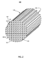
図1Aは、複数の交差壁110を含むハニカム本体100を示したものであり、交差壁110は、対向する端面114、116間に軸方向に延在する、相互に隣接したセルチャネル112を形成する。図1Bは、図1Aのハニカム本体100の概略断面図を示している。図1Cは、図1Aのハニカム本体100の概略上面図を示している。「セル」は本書において、ハニカム本体の断面における交差壁を称する際に一般に使用され、「チャネル」は、端面114、116間に延在するセルを称する際に一般に使用される。「セルチャネル」並びにセルおよびチャネルは、同じ意味で使用され得る。「部分セル」または「部分セルチャネル」120とは、本書で使用される場合、輪郭形成されたハニカム本体100(ハニカムコア104)の外周118の位置で、交差壁110が間隙122を有しているセルまたはチャネルを称する。図1Aの位置付けのハニカム本体100に関し、上面114は第1の端面を称し、底面116は第2の端面を称するが、それ以外にこれらの端面は、ハニカム本体100の向きによって限定されるものではない。上面114がハニカム本体100の入口面かつ底面116がその出口面でもよいし、あるいは上面114がハニカム本体100の出口面かつ底面116がその入口面でもよい。
FIG. 1A shows a
セル密度は、1平方インチ(6.45cm2)当たり約100から900セル(cpsi)(約15.5から約140セル/cm2)の間とすることができる。典型的なセル壁の厚さは、約0.025mmから約1.5mm(約1から60ミル)の範囲とすることができる。例えばハニカム本体100の幾何学的形状は、400cpsi(約62セル/cm2)で、壁の厚さが約8ミル(0.2mm)(400/8)または壁の厚さが約6ミル(0.15mm)(400/6)のものでもよい。他の幾何学的形状としては、例えば、100/17、200/12、200/19、270/19、600/4、400/4、600/3、および900/2が挙げられる。本書では、ハニカム本体100は一般的にハニカム構造体を含むと意図されているが、正方形の構造に厳密に限定されたものではなく、例えば、六角形、八角形、三角形、長方形、または任意の他の適切なセル形状を使用することができる。さらに、セルで構成されるハニカム本体100の断面は円形であるが、これに限定されるものではなく、例えばその断面は、楕円形、正方形、長方形、または他の所望の形状とすることができる。
Cell density can be between 1 square inch (6.45 cm 2) per about 100 to 900 cells (cpsi) (from about 15.5 to about 140 cells / cm 2). Typical cell wall thicknesses can range from about 0.025 mm to about 1.5 mm (about 1 to 60 mils). For example, the geometry of the
ハニカム本体100は概して、外周118を有するハニカムコア104と、外皮124とを備えている。外皮124は共押出しされたものでもよいし、または輪郭形成作業の後に塗布されたものでもよい。図2は、輪郭形成後かつ外皮形成前のハニカムコア104の例示的な実施形態の斜視図を示している。ハニカムコア104は、生の、輪郭形成および外皮形成の前に乾燥させたものでもよいし、あるいは焼成したものでもよい。輪郭形成されたハニカムコア104の最外部の外周118に位置する壁110は、部分セル120並びにセル112を形成し得る。この部分セル120は一般に、セル112の外側に空間を設ける。ただしセル112を形成している壁110が外周118で合流する場合には、セル112が最外部になり得る。部分セル120の壁110の最外部分と、いくつかのセル112の最外角部126が、輪郭形成されたハニカムコア104の外周118を形成する。
The
本開示の例示的な実施形態は、単一のモノリスから形成され得る、またはモノリスを形成するよう一緒にセメント接合されたセグメントから形成され得る、図2に示されているようなハニカムコア104を備えた、セラミック物品に関する。ハニカムコア104は、入口面114と出口面116との間にセルチャネル112および部分セルチャネル120を画成して入口面114から出口面116まで延在する、複数のチャネル壁110と、入口面114から出口面116まで延在する外周118とを含み、この部分セルチャネル120は、ハニカムコア104の外周118に隣接している。外皮124が、部分セルチャネルの全容積の大部分が図1A、1B、および1Cに示されているように入口面114から出口面116まで開口するようにハニカムコア104の外周118上に配置されて、ハニカム本体100を形成する。本開示は事後塗布の外皮に関するが、この事後塗布の外皮を、共押出しされた外皮上に配置してもよい。
Exemplary embodiments of the present disclosure include a
これらの例示的な実施形態において、ハニカムコア104は、コージライトなどのセラミック材料から形成され得、あるいは他の事例では、炭化ケイ素、窒化ケイ素、チタン酸アルミニウム、アルミナ、および/またはムライト、またはこれらの組合せなどの、他のセラミック材料から作製され得る。
In these exemplary embodiments, the
ハニカム本体は、ハニカムモノリス体を形成するのに適した任意の従来のプロセスに従って形成され得る。例えば、可塑化セラミック形成バッチ組成物を、押出成形、射出成形、鋳込み成形、遠心鋳造法、加圧鋳込成形、乾式成形などの、任意の既知の従来のセラミック成形プロセスによって生素地へと成形してもよい。典型的には、ハニカム構造体は押出成形プロセスによって形成され、このときセラミック材料が生の状態に押出しされ、その後この生の状態のものを焼成して最終的なセラミック構造体が形成される。例示的な実施形態において押出成形は、排出端に取り付けられたダイアセンブリを備えている、水圧ラム押出プレス、2段階脱気単一オージェ押出機、または2軸スクリューミキサーを用いて行うことができる。押出しされた材料を切断して、エンジン製造業者の要望にあった形状およびサイズのフィルタ本体など、ハニカム構造体を生成することができる。押出しされた材料は、ハニカム構造体を形成するよう一緒に接続または接合される、ハニカムセグメントでもよい。これらの押出しされた生素地は、任意のサイズまたは形状とすることができる。 The honeycomb body can be formed according to any conventional process suitable for forming a honeycomb monolith body. For example, a plasticized ceramic forming batch composition is formed into a green body by any known conventional ceramic forming process such as extrusion, injection molding, casting, centrifugal casting, pressure casting, dry forming, etc. May be. Typically, the honeycomb structure is formed by an extrusion process, in which the ceramic material is extruded to a green state, which is then fired to form the final ceramic structure. In exemplary embodiments, extrusion can be performed using a hydraulic ram extrusion press, a two-stage degassing single Auger extruder, or a twin screw mixer with a die assembly attached to the discharge end. . The extruded material can be cut to produce a honeycomb structure, such as a filter body of a shape and size that meets the demands of the engine manufacturer. The extruded material may be honeycomb segments that are connected or joined together to form a honeycomb structure. These extruded green bodies can be of any size or shape.
一般に、セラミックハニカム構造体が押出しされると、構造体の長さに沿って固体の外部表面が提供される。しかしながら特定の状況下では、この外部表面を除去することが必要になり得る。例えば生の押出しされたハニカム構造体は、押出しされた外部表面を除去することによって所望の形状およびサイズに成形され得る。あるいは生のハニカム構造体を焼成し、次いで研削して、外部押出表面と、所望の形状およびサイズを得るために必要な多孔質壁構造の任意の部分とを除去することによって、所望の形状およびサイズとしてもよい。成形は、所望の形状およびサイズを達成するためにハニカム構造体の外側押出表面を、切断、研磨、または研削するなど、当技術において既知の任意の手段で達成することができる。 Generally, when a ceramic honeycomb structure is extruded, a solid outer surface is provided along the length of the structure. However, under certain circumstances, it may be necessary to remove this external surface. For example, a raw extruded honeycomb structure can be formed into a desired shape and size by removing the extruded outer surface. Alternatively, the raw honeycomb structure can be fired and then ground to remove the external extruded surface and any portion of the porous wall structure necessary to obtain the desired shape and size, and the desired shape and It is good also as a size. Molding can be accomplished by any means known in the art, such as cutting, polishing, or grinding the outer extruded surface of the honeycomb structure to achieve the desired shape and size.
同様にハニカムセグメントは、ハニカム構造体に一体化される前に、押出しされた外部表面を除去することによって所望の形状およびサイズに成形され得る。あるいはハニカムセグメントを一体化してハニカム構造体を形成し、この形成されたハニカム構造体を所望の形状およびサイズに成形してもよい。 Similarly, the honeycomb segments can be formed into the desired shape and size by removing the extruded outer surface before being integrated into the honeycomb structure. Alternatively, the honeycomb segments may be integrated to form a honeycomb structure, and the formed honeycomb structure may be formed into a desired shape and size.
一旦所望の形状およびサイズが得られると、このサイズに合わせて成形された本体の外周に外皮材料を塗布して、本体上に新たな外部表面、すなわち外皮を形成することができる。典型的には、ハニカム本体の端部は外皮材料でカバーされないが、所望であれば特定の通路を塞いでもよい。一旦外皮組成物がハニカム構造体に塗布されると、外皮組成物を乾燥および/またはか焼してもよい。いくつかの実施形態では、低温硬化セメント組成物をハニカム構造体に塗布してもよい。いくつかの実施形態において、それを覆うようにセメントが塗布されるハニカムコアは、焼成されたセラミック材料を含む。他の実施形態においてハニカムコアは、生素地またはか焼体を含む。いくつかの事例では、か焼されたハニカム構造体の最終的な焼成を触媒化プロセスの際に行ってもよい。 Once the desired shape and size is obtained, a skin material can be applied to the outer periphery of the body molded to this size to form a new exterior surface, or skin, on the body. Typically, the ends of the honeycomb body are not covered with a skin material, but certain passages may be blocked if desired. Once the skin composition is applied to the honeycomb structure, the skin composition may be dried and / or calcined. In some embodiments, a low temperature setting cement composition may be applied to the honeycomb structure. In some embodiments, the honeycomb core to which the cement is applied to cover it comprises a fired ceramic material. In other embodiments, the honeycomb core includes a green body or a calcined body. In some cases, final firing of the calcined honeycomb structure may occur during the catalyzed process.
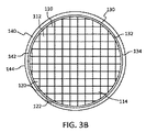
これらの例示的な実施形態では、ハニカムコアの所望の形状およびサイズが一旦得られると、ハニカムコア上にシートを配置し、シート上に外皮バッチを配置する。図3Aは、外周118上に配置されたシート130を備えた、ハニカムコア104の概略端面図である。このシートは内側表面132および外側表面134を有している。内側表面132は、巻き付ける作業などによって外周118上に配置され、この作業においてシートの内側表面132は、シートの外側表面134に重複部分136で重なり得る。あるいはシート130は、重複部分を含まないスリーブの形を成したものでもよい。シート130がスリーブの形を成している場合、シート130のハニカムコア104への適用は、シート130をハニカムコア104の端面114、116を越えて滑らせて、外周118上に配置し得る作業を含み得る。
In these exemplary embodiments, once the desired shape and size of the honeycomb core is obtained, a sheet is placed on the honeycomb core and a skin batch is placed on the sheet. FIG. 3A is a schematic end view of the
シート130は、輪郭形成されたハニカムコア104の外周118を形成する、部分セル120の壁110の最外部分とセル112の最外角部126との上に配置され得る。シート130は、外皮バッチが部分セル120を充填するのを防ぐよう障壁を提供する。図3Bは、外周118上に配置されたシート130と、シート130の外側表面134上に配置された外皮バッチ層140とを備えている、ハニカムコア104の概略端面図を示している。外皮バッチ層140は、シート130の外側表面134に接触している内側表面142と、ハニカム本体100の外周を形成する外側表面144とを有している。
The
外皮バッチは、ドクターブレード工程、軸方向外皮形成(axial skinning)工程、スプレー鋳造工程、またはテープ成形工程などによって、シート130に包まれたハニカムコア104に塗布され得る。シート130は、外皮バッチ層140が部分セル120を充填するのを防ぐが、しかしながら外皮バッチはシート130を浸透して、輪郭形成されたハニカムコア104の外周118を形成する、部分セル120の壁110の最外部分およびいくつかのセル112の最外角部126に接触し得る。こういった意味でシート130は、外皮バッチをハニカムコアの壁110に接触させることができる多孔質のものでもよい。ハニカムコアの壁110に接触した外皮バッチは、外皮バッチが硬化されると外皮バッチ層140をハニカムコア104に接合させ、ハニカム本体を形成する。外皮バッチの硬化は、シート130の犠牲を含み得る。例えば外側外皮を形成するために外皮バッチを焼成またはか焼して、シート130を焼き尽くすと、入口面114から出口面116まで開口した外皮形成された部分セルチャネル120の部分を残すことができる。
The skin batch may be applied to the
シート130は、例えば水で濡らしたものでもよく、またはシート130は外皮124の構成成分を含み得る。シート130を濡らすと、ハニカムコア104上にシート130を配置するのを助けることができる。シート130を濡らしかつ乾燥させると、シート130をハニカムコア104に対して収縮させることができ、続く外皮形成作業をさらに助けることができる。外皮124または外皮層140の、1以上の構成成分を含浸させたシート130は、外皮124のハニカムコア104への接合を高めることができると同時に亀裂などの欠陥を防ぐことができる。1つのこの構成成分は、コロイド状シリカ、コロイド状アルミナなどの無機バインダ、およびこれらの組合せとすることができる。
The
例示的な実施形態においてシート130は、多孔質織布シート、多孔質不織布シート、非多孔質織布シート、および非多孔質不織布シート、のうちの少なくとも1つとすることができる。このシートは特に限定されるものではなく、天然材料および合成材料を含み得、シートは裏に接着剤を有するものでも、あるいは有していないものでもよい。シート材料の例としては、ガラス繊維テープ、ガラス繊維クロス、セルロース繊維、さらにポリエチレン繊維クロス、ナイロン繊維クロス、およびポリエステル繊維クロスなどのポリマーが挙げられ、シート材料の他の例としては、炭素繊維織物、紙、キムワイプ(Kimwipe)(登録商標)などのペーパーティッシュ、網、さらに綿、絹、ヘンプ、またはリネンなどの天然繊維クロスが挙げられる。多孔率は、ナノメートルスケールからミリメートルスケールの範囲でもよい。シートの厚さは同様の範囲、例えば数μmから数ミリメートルでもよい。例えばシートの厚さは約50から1500μmでもよく、また孔の開口は約1μmから約1500μmでもよい。シート130が多孔質である場合、外皮バッチの構成成分がシート130に浸透して、外皮層140をハニカムコア104に接合させることができる。シート130が非多孔質である場合には、か焼または硬化の際に外皮層の構成成分がシート130に浸透することによって、外皮材料層140はハニカムコア104の外周118に接合することができる。シート130が非多孔質である場合、か焼、焼成、または硬化の際にシート130が反応し得ることにより、外皮材料層140はハニカムコア104の外周118に接合することができる。
In an exemplary embodiment, the
シートのパラメータを特徴付ける別の非限定的方法として、シートの密度を使用することができる。例えばシートの密度は、約0.1オンス/平方ヤード(3.4g/m2)から約50オンス/平方ヤード(1695.3g/m2)でもよい。例えばシート材料は、約0.7オンス/平方ヤード(23.7g/m2)、約1.5オンス/平方ヤード(50.9g/m2)、約2オンス/平方ヤード(67.8g/m2)、約2.7オンス/平方ヤード(91.5g/m2)、またはさらには約3.2オンス/平方ヤード(108.5g/m2)でもよい。 As another non-limiting method of characterizing sheet parameters, sheet density can be used. For example the density of the sheet may about 0.1 oz / yd (3.4 g / m 2) even about 50 oz / yd (1695.3g / m 2). For example, the sheet material may be about 0.7 ounces / square yard (23.7 g / m 2 ), about 1.5 ounces / square yard (50.9 g / m 2 ), about 2 ounces / square yard (67.8 g / m 2 ). m 2 ), about 2.7 ounces / square yard (91.5 g / m 2 ), or even about 3.2 ounces / square yard (108.5 g / m 2 ).
代わりの例示的な実施形態において、外皮バッチ層140は、シート130をハニカムコア104上に配置する作業の前にシート130上に配置され得る。こういった事例では、バッチ層140を外側表面134上に配置して備えたシート130を、上述したようにハニカムコア104に適用してもよい。
In an alternative exemplary embodiment, the
シート130は、外周118上にシート130を配置する前に、外皮バッチ層をシートの内側表面132上に配置して備えたものでもよい。シート130は、内側表面132上に配置された外皮バッチ層が部分セル120を充填するのを防ぐ。外皮バッチが硬化すると、ハニカムコアの壁110に接触している内側表面132上の外皮バッチが、外皮バッチ層140をハニカムコア104に接合させて、ハニカム本体100を形成する。この例示的な実施形態では、硬化、焼成、またはか焼の際にシート130を犠牲にし、または変形させて、外側外皮124を形成する。外皮バッチセメントが内側表面132および外側表面134上に配置される場合、バッチセメントはシート130の内側および外側で同じ組成を有してもよいし、あるいはバッチセメントはシートの内側および外側で異なる組成を有していてもよい。例えば、ハニカムコア104の所望の物理的性質(弾性係数(EMOD)、熱膨張係数(CTE)、破壊係数(MOR)など)に合った外皮124のために、第1の組成物を内側表面132に塗布してもよく、また異なるMOR、EMOD、CTEなど、外皮124の外側表面の所望の物理的性質のために、第2の組成物を外側表面134に適用してもよい。
The
代わりの実施形態では、充填材138をハニカムコア104の外周118上に配置して、外皮バッチ材料を塗布する前に部分セル120を充填してもよい(図3C)。充填材138を部分セル120内に適用し、さらに、輪郭形成されたハニカムコア104の外周118を形成する部分セル120の壁110の最外部分といくつかのセル112の最外角部126とを露出するように、充填材138を取り除いてもよい。このように充填材138を含むハニカム構造体104に外皮バッチを塗布すると、外皮バッチは、輪郭形成されたハニカムコア104の外周118を形成する部分セル120の壁110の最外部分といくつかのセル112の最外角部126とに接触し得る。外皮バッチが硬化すると、ハニカムコアの壁110に接触している外皮バッチが、外皮バッチ層をハニカムコア104に接合させて、ハニカム本体100を形成する。外皮バッチの硬化は、充填材138の犠牲を含み得る。例えば外側外皮124を形成するために外皮バッチを焼成またはか焼して、充填材138を焼き尽くすと、入口面114から出口面116まで開口した外皮形成された部分セルチャネル120の部分を残すことができる。
In an alternative embodiment, a
充填材138は、ワックス、ナフタレンなどを含み得る。充填材138は、室温でペーストであり、乾燥、硬化、か焼、または焼成温度などの高温で、揮発するものでもよい。
本書で説明したようなやり方で、シート130またはハニカム構造体上の充填材138に、外皮材料が塗布されると、外皮材料は随意的に乾燥および/または焼成され得る。随意的な乾燥ステップは、外皮材料内に存在し得る任意の液体ビヒクルを少なくとも実質的に除去するのに十分な温度および時間で、外皮材料を湿度制御雰囲気内で最初に加熱するステップを含み得る。本書では、任意の液体ビヒクルを少なくとも実質的に除去するとは、焼成前に外皮材料内に存在している液体ビヒクルの、少なくとも95%、少なくとも98%、少なくとも99%、またはさらには少なくとも99.9%の除去を含む。液体ビヒクルの除去に適した例示的な非限定的乾燥条件は、外皮材料を少なくとも50℃、少なくとも60℃、少なくとも70℃、少なくとも80℃、少なくとも90℃、少なくとも100℃、少なくとも110℃、少なくとも120℃、少なくとも130℃、少なくとも140℃、少なくとも150℃、少なくとも160℃、少なくとも170℃、少なくとも180℃、少なくとも190℃、またはさらには少なくとも200℃の温度で加熱するものを含む。一実施の形態において、液体ビヒクルを少なくとも実質的に除去するのに有効な条件は、外皮材料を湿度制御された空気などの雰囲気内で、60℃から120℃の範囲の温度で加熱するものを含む。さらに加熱は、例えば、湿度制御雰囲気内での、熱風乾燥、RFおよび/またはマイクロ波乾燥など、任意の従来の既知の方法によって実現することができる。
Once the skin material is applied to the
随意的な焼成ステップは、外皮材料を主結晶相セラミック組成物へと変換するのに適した条件を含むものでもよく、塗布された外皮材料を備えたハニカムの、800℃超、900℃、さらには1000℃超ものピーク温度までの加熱を含み得る。加熱中、約120℃/hrの傾斜率を使用してもよく、その後ピーク温度で約3時間保持し、次いで約240℃/hrで冷却する。 The optional firing step may include conditions suitable for converting the skin material into a main crystalline phase ceramic composition, such as over 800 ° C., 900 ° C., and more of the honeycomb with the coated skin material. Can include heating to peak temperatures in excess of 1000 ° C. During heating, a ramp rate of about 120 ° C./hr may be used, then held at peak temperature for about 3 hours and then cooled at about 240 ° C./hr.
本書で開示される外皮材料は、「低温硬化」外皮を採用する外皮形成プロセスにおいて使用され得るセメント材料など、例えば100℃未満の温度、さらには50℃未満の温度など、200℃未満の温度で硬化するものを含み得る。低温硬化外皮形成では、ハニカムのチャネル壁のシールを形成するために、外皮形成混合物の乾燥のみが必要とされる。低温硬化外皮形成プロセスが採用される場合、外皮形成されたハニカムを35〜110℃の範囲の温度まで加熱すると、乾燥を速めるのに有用になり得る。いくつかの低温硬化外皮形成プロセスでは、続く処理ステップの過程で(例えば、触媒化またはキャニングの過程で)、あるいは最初の使用時に(例えば、排気系で)、シート130などの残存する一時的なバインダの副生成物の除去およびシールの強化など、最終的な外皮の強化が起こり得ると予想される。
The skin material disclosed herein is a cement material that can be used in a skin forming process that employs a “cold cure” skin, such as a temperature below 100 ° C., or even below 50 ° C., such as a temperature below 50 ° C. It can include those that cure. In low temperature cure skin formation, only the skin formation mixture needs to be dried to form a seal on the channel wall of the honeycomb. If a low temperature cure skin formation process is employed, heating the skinned honeycomb to a temperature in the range of 35-110 ° C. can be useful to speed up drying. In some low temperature cure skin formation processes, remaining temporary, such as
例えば、低温硬化外皮形成を採用することができる例示的な組成物としては、チタン酸アルミニウム、コージライト、溶融シリカ、ムライト、およびアルミナのうちの少なくとも1つなど、少なくとも1つの無機粉末を含む耐火充填材、および、ゲル状のコロイド状シリカなどゲル状無機バインダ、を含むものが挙げられ、この無機粉末のバイモーダルまたはモノサイズの中央粒径(D50)は、例えばモノサイズに対しては30から40μmなど、15から50μmであり、さらにバイモーダルなサイズ構成における第2の粒径に対しては、約150μmから約250μmなど、約150μmから約300μmの範囲である。無機バインダをゲル化するために、塩酸、硫酸、硝酸、クエン酸、および酢酸、水酸化アンモニウム、水酸化ナトリウム、およびトリエタノールアミン(以下「TEA」)、のうちの少なくとも1つなど、少なくとも1つのゲル化剤を、バッチ処理の前に(例えば、ゲル状無機バインダを含む予混合物として)あるいはバッチ処理の際に、加えてもよい。あるいは、ゲル化されていない組成物を使用してもよい。このような組成物は、例えば100℃未満、さらには約25℃を含む50℃未満など、200℃未満の温度で、多孔質セラミックハニカム本体において硬化する(かつそれにより、チャネル壁に恒久的にシールされる)外皮を提供し得る。外皮形成に使用されるセメント組成物のさらなる非限定的な例示的実施形態を以下で論じる。 For example, exemplary compositions that can employ low temperature cure skin formation include refractories that include at least one inorganic powder, such as at least one of aluminum titanate, cordierite, fused silica, mullite, and alumina. Examples include fillers and gel inorganic binders such as gel colloidal silica. The bimodal or mono-sized median particle size (D 50 ) of the inorganic powder is, for example, for mono size For a second particle size in a bimodal size configuration, such as 30-40 μm, and in the range of about 150 μm to about 300 μm, such as about 150 μm to about 250 μm. At least 1 such as hydrochloric acid, sulfuric acid, nitric acid, citric acid, and at least one of acetic acid, ammonium hydroxide, sodium hydroxide, and triethanolamine (hereinafter “TEA”) to gel the inorganic binder; Two gelling agents may be added prior to batch processing (eg, as a premix containing a gelled inorganic binder) or during batch processing. Alternatively, a non-gelled composition may be used. Such a composition cures in the porous ceramic honeycomb body at a temperature below 200 ° C., for example below 100 ° C., or even below about 50 ° C., including about 25 ° C. (and thereby permanently on the channel walls). Can provide a skin that is sealed). Further non-limiting exemplary embodiments of cement compositions used for hull formation are discussed below.
外皮組成物は、その内容がその全体を参照することにより本書に組み込まれる、米国仮特許出願第61/602,883号明細書および米国特許出願第13/302,262号明細書に記載されている。例示的な実施形態によれば、外皮組成物は、低熱膨張充填材としてのガラス粉末と、バインダと、ガラスベースのセメントの固体成分を保持するための溶剤またはビヒクルとを含むセメントなど、単一のガラス粉末組成物でもよい。ガラス粉末充填材のガラスは、非晶質溶融シリカ(SiO2)、粉砕コージライト、ATグロッグ、またはシリカスートでもよい。ガラス粉末充填材の中央粒径(D50)は10から20μmの間でもよく、最小粒径は7μmから75μmの間、および最大粒径は50μmから70μmの間でもよい。粒径は、質量に基づく球相当径として決定した。ガラス粉末充填材は、例えば、セメントの全無機成分の60〜80質量%を構成し得る。適切なシリカ粉末充填材は、例えば商標名Teco−Silで市販されており、米国テネシー州所在のCE Minerals of Tennessee Electro Minerals Incorporatedから入手可能である。本書における全ての粒径の測定は、他に示されていなければ、Microtrac Inc.の粒径分析器で行われた。 The skin composition is described in US Provisional Patent Application No. 61 / 602,883 and US Patent Application No. 13 / 302,262, the contents of which are hereby incorporated by reference in their entirety. Yes. According to an exemplary embodiment, the skin composition is a single piece, such as a cement comprising glass powder as a low thermal expansion filler, a binder, and a solvent or vehicle to hold the solid components of the glass-based cement. The glass powder composition may be used. The glass of the glass powder filler may be amorphous fused silica (SiO 2 ), ground cordierite, AT grog, or silica soot. The median particle size (D 50 ) of the glass powder filler may be between 10 and 20 μm, the minimum particle size may be between 7 μm and 75 μm, and the maximum particle size may be between 50 μm and 70 μm. The particle size was determined as a sphere equivalent diameter based on mass. The glass powder filler can constitute, for example, 60 to 80% by mass of the total inorganic components of the cement. Suitable silica powder fillers are commercially available, for example, under the trade name Teco-Sil and are available from CE Minerals of Tennessee Electro Minerals Incorporated, Tennessee, USA. All particle size measurements in this document were performed on a Microtrac Inc. particle size analyzer unless otherwise indicated.
例示的な実施形態によれば、外皮組成物は、低熱膨張充填材として第1の(細かい)ガラス粉末、低熱膨張充填材として第2の(粗い)ガラス粉末、バインダ、およびガラスベースのセメントの固体成分を保持するための溶剤またはビヒクル、を含む、二元的ガラス粉末組成物から形成された、非晶質ガラスベースのセメントを含み得る。第1のガラス粉末充填材および第2のガラス粉末充填材のガラスは両方とも、約1μmを超える粒径を有する非晶質溶融シリカでもよい。ガラス粉末充填材の粒径の分布は、ガラス粉末充填材の約1μmを超える粒径に対する分布が粒径の複数の最頻値(極大)を呈することから、マルチモーダルとなり得る。一実施の形態において、非晶質ガラスベースのセメントは、約1μmを超える粒径に対し非晶質ガラス粒子のバイモーダル粒径分布を有する。ガラスベースのセメントは第1のガラス粉末充填材を含み得、第1のガラス粉末充填材の中央(D50)粒径は、約10から約50μm、約15μmから約50μm、約20μmから約45μm、または約30μmから約45μmの範囲でもよく、D10は約1μmから約10μmの範囲、およびD90は約25μmから約125μmの範囲でもよい。第2のガラス粉末充填材の中央(D50)粒径は、約150μmから約300μmの範囲、約150μmから約250μmの範囲、約170μmから約230μmの範囲、約180μmから約220μmの範囲でもよく、D10は約100μmから約150μmの範囲、およびD90は約250μmから約350μmの範囲でもよい。粒径は、質量に基づく球相当径として決定した。本書では、D50という用語は粒径の分布の中央値を表し、D10は、分布の10%がこの粒径よりも小さいことを示す粒径をμmで表したものであり、D90は、分布の90%がこの粒径よりも小さいことを示す粒径をμmで表したものである。二元的なガラスベースのセメントは、例えば、セメントの無機固体成分の全質量の、約20から約60質量%の範囲、約25質量%から約50質量%の範囲、約25質量%から約40質量%の範囲、または約25質量%から約35質量%の範囲の量の、第1のガラス粉末充填材を含有し得る。このガラスベースのセメントは、例えば、セメントの無機固体成分の全質量の、約10質量%から約40質量%の範囲、約15質量%から約40質量%の範囲、約20質量%から約35質量%の範囲の量の、第2のガラス粉末充填材を含有し得る。 According to an exemplary embodiment, the skin composition comprises a first (fine) glass powder as a low thermal expansion filler, a second (coarse) glass powder as a low thermal expansion filler, a binder, and a glass-based cement. It may include an amorphous glass-based cement formed from a binary glass powder composition that includes a solvent or vehicle to retain the solid components. Both the glass of the first glass powder filler and the second glass powder filler may be amorphous fused silica having a particle size greater than about 1 μm. The particle size distribution of the glass powder filler can be multimodal because the distribution of the glass powder filler with respect to the particle size exceeding about 1 μm exhibits a plurality of mode values (local maximum) of the particle size. In one embodiment, the amorphous glass-based cement has a bimodal particle size distribution of amorphous glass particles for particle sizes greater than about 1 μm. The glass-based cement may include a first glass powder filler, wherein the first glass powder filler has a center (D 50 ) particle size of about 10 to about 50 μm, about 15 μm to about 50 μm, about 20 μm to about 45 μm. , Or in the range of about 30 μm to about 45 μm, D 10 may be in the range of about 1 μm to about 10 μm, and D 90 may be in the range of about 25 μm to about 125 μm. The central (D 50 ) particle size of the second glass powder filler may be in the range of about 150 μm to about 300 μm, in the range of about 150 μm to about 250 μm, in the range of about 170 μm to about 230 μm, in the range of about 180 μm to about 220 μm. , D 10 may range from about 100 μm to about 150 μm, and D 90 may range from about 250 μm to about 350 μm. The particle size was determined as a sphere equivalent diameter based on mass. In this document, the term D 50 represents the median of the particle size distribution, D 10 is the particle size in μm indicating that 10% of the distribution is smaller than this particle size, and D 90 is , The particle diameter in μm indicating that 90% of the distribution is smaller than this particle diameter. Dual glass-based cements, for example, range from about 20 to about 60%, from about 25% to about 50%, from about 25% to about 25% by weight of the total weight of the inorganic solid component of the cement. The first glass powder filler may be included in an amount in the range of 40% by weight, or in the range of about 25% to about 35% by weight. The glass-based cement can be, for example, in the range of about 10% to about 40%, in the range of about 15% to about 40%, about 20% to about 35%, based on the total weight of the inorganic solid component of the cement. An amount in the range of mass% may contain a second glass powder filler.
1つの例示的な実施形態において、第1のガラス粉末充填材のD50は、約34μmから約40μmの範囲でもよく、また第2のガラス粉末充填材の中央粒径は、約190μmから約280μmの範囲である。一例において、第1のガラス粉末充填材のD10は約6.0μm、D50は約34.9μm、さらにD90は約99μmである。別の例において、第1のガラス粉末充填材のD10は約6.7μm、D50は約39.8μm、さらにD90は約110.9μmである。さらに別の例において、第1のガラス粉末充填材のD10は約2.7μm、D50は約13.8μm、さらにD90は約37.8μmであり、さらに別の例として第1のガラス粉末充填材のD10は約2.8μm、D50は約17.2μm、さらにD90は約47.9μmである。 In one exemplary embodiment, the D 50 of the first glass powder filler may be in the range of about 34 μm to about 40 μm, and the median particle size of the second glass powder filler is about 190 μm to about 280 μm. Range. In one example, D 10 of the first glass powder filler is about 6.0 μm, D 50 is about 34.9 μm, and D 90 is about 99 μm. In another example, D 10 of the first glass powder filler is about 6.7 μm, D 50 is about 39.8 μm, and D 90 is about 110.9 μm. In yet another example, the first glass powder filler D 10 is about 2.7 μm, D 50 is about 13.8 μm, and D 90 is about 37.8 μm. about D 10 of the powder filler 2.8 .mu.m, D50 is about 17.2Myuemu, more D 90 is about 47.9Myuemu.
第2のガラス粉末充填材と第1のガラス粉末充填材との比は、約1:3.5から約1:1、約1:3から約1:1、約1:2.5から約1:1、約1:2から約1:1、または約1:1.5から約1:1など、約1:4から約1:1の範囲でもよい。例示的な実施形態において、第2のガラス粉末充填材と第1のガラス粉末充填材との比率は1:1である。 The ratio of the second glass powder filler to the first glass powder filler is about 1: 3.5 to about 1: 1, about 1: 3 to about 1: 1, about 1: 2.5 to about It may range from about 1: 4 to about 1: 1, such as 1: 1, about 1: 2 to about 1: 1, or about 1: 1.5 to about 1: 1. In an exemplary embodiment, the ratio of the second glass powder filler to the first glass powder filler is 1: 1.
本開示のセメント組成物を提供するために、上記無機粉末のいずれかを含む無機粉末と任意の随意的な無機添加剤成分とを、適切な有機および/または無機バインダ材料と一緒に混合してもよい。有機バインダ材料は、セルロースエーテル、メチルセルロース、エチルセルロース、ポリビニルアルコール、ポリエチレンオキシドなどの1以上の有機材料、またはいくつかの実施形態では、Actigum(登録商標)などのゴム状材料、キサンタンガム、またはラテックスを含み得る。例えば、A4メトセルは適切な有機バインダである。メトセルA4は、ダウケミカルから入手可能な水溶性メチルセルロースポリマーバインダである。適切な無機バインダは、水などの適切な液体中に懸濁されたナノメートルスケールのシリカまたはアルミナ粒子を含む、コロイド状シリカまたはアルミナを含み得る。無機バインダ材料は、セメント組成物内に、セメント内に存在している無機固体の全質量の約10%未満の量で存在し得、いくつかの例示的な実施形態では、無機バインダは約5質量%以下の量で存在し、また特定の他の例示的な実施形態では、有機バインダの流体部分を考慮して約2質量%から約4質量%の範囲で存在する(このとき流体部分の質量への寄与は除かれる)。適切なコロイド状シリカバインダ材料は、W.R.グレース社製のLudox HS40である。典型的なコロイド状バインダ材料は、脱イオン水ビヒクルにおける懸濁剤として、質量でおよそ40%の固体材料を含み得る。 To provide a cement composition of the present disclosure, an inorganic powder comprising any of the above inorganic powders and any optional inorganic additive components are mixed together with a suitable organic and / or inorganic binder material. Also good. The organic binder material includes one or more organic materials such as cellulose ether, methyl cellulose, ethyl cellulose, polyvinyl alcohol, polyethylene oxide, or in some embodiments, a rubbery material such as Actigum®, xanthan gum, or latex. obtain. For example, A4 methocel is a suitable organic binder. Methocel A4 is a water-soluble methylcellulose polymer binder available from Dow Chemical. Suitable inorganic binders can include colloidal silica or alumina, including nanometer scale silica or alumina particles suspended in a suitable liquid such as water. The inorganic binder material may be present in the cement composition in an amount less than about 10% of the total mass of inorganic solids present in the cement, and in some exemplary embodiments, the inorganic binder is about 5%. And in certain other exemplary embodiments, it is present in the range of about 2% to about 4% by weight, taking into account the fluid portion of the organic binder (the fluid portion of The contribution to mass is excluded). Suitable colloidal silica binder materials are described in W.W. R. Ludox HS40 manufactured by Grace. A typical colloidal binder material may contain approximately 40% solid material by mass as a suspending agent in a deionized water vehicle.
いくつかの例示的な実施形態において、上述した単一のおよび二元的なガラス粉末セメントは、無機繊維補強材料をさらに含んでもよい。例えばアルミノケイ酸塩繊維をセメント混合物に加えて、外皮塗布後にハニカム構造体を強化することができる。例えばセメントは無機繊維材料を、セメントの無機固体成分の全質量の約25から約50質量%、約30から約50質量%、またいくつかの実施形態ではセメントの無機固体成分の全質量の約35から約45質量%含んでもよい。特定の他の実施形態において、無機繊維補強材料は、セメント組成物の無機固体の全質量の割合として、約36質量%から約43質量%の量で存在し得る。適切な無機繊維補強材料は、ユニフラックスから入手可能なFiberfrax QF180であるが、任意の高アスペクト比の耐火性粒子を使用することもできる。 In some exemplary embodiments, the single and dual glass powder cements described above may further include an inorganic fiber reinforcement material. For example, aluminosilicate fibers can be added to the cement mixture to reinforce the honeycomb structure after skin coating. For example, the cement contains inorganic fiber material from about 25 to about 50% by weight, from about 30 to about 50% by weight of the total mass of the inorganic solid component of the cement, and in some embodiments, from about 30% of the total mass of the inorganic solid component of the cement. 35 to about 45% by weight may be included. In certain other embodiments, the inorganic fiber reinforcement material may be present in an amount from about 36% to about 43% by weight as a percentage of the total weight of inorganic solids in the cement composition. A suitable inorganic fiber reinforcement material is Fiberfrax QF180 available from Uniflux, although any high aspect ratio refractory particles can be used.
典型的には、流動可能なまたはペースト状の一貫性を実現するための液体ビヒクルまたは溶剤として、脱イオン(DI)水などの水を挙げたが、他の材料を使用することもできる。液体ビヒクルの内容物は、上乗せ添加として、セメント混合物の無機成分の約30質量%以下の量で存在し得、セメント混合物の無機成分の約10質量%から約25質量%の範囲でもよい。しかしながら液体ビヒクルは、典型的には、セメントを塗布し易いものにするのに適した粘度を得るように調節される。 Typically, water such as deionized (DI) water has been mentioned as the liquid vehicle or solvent to achieve flowable or pasty consistency, but other materials can be used. The contents of the liquid vehicle can be present as an overload in an amount up to about 30% by weight of the inorganic component of the cement mixture, and may range from about 10% to about 25% by weight of the inorganic component of the cement mixture. However, the liquid vehicle is typically adjusted to obtain a viscosity suitable for making the cement easy to apply.
いくつかの実施形態においてセメントは、随意的に、セメントとハニカム本体との間の付着を高めるための付着促進剤などの有機改質剤をさらに含有し得る。例えばMichem4983は、この目的に適していることが見出された。 In some embodiments, the cement may optionally further contain an organic modifier, such as an adhesion promoter to enhance adhesion between the cement and the honeycomb body. For example, Michel 4983 has been found to be suitable for this purpose.
特定の例示的な実施形態において、セメント混合物は、例えば800℃未満、さらには600℃未満など、またさらには400℃未満など、さらには200℃未満など、1000℃未満の温度で硬化する。特定の例示的な実施形態において、セメント混合物は、室温(すなわち、約23℃)で硬化することができる。 In certain exemplary embodiments, the cement mixture cures at a temperature of less than 1000 ° C., such as less than 800 ° C., even less than 600 ° C., or even less than 400 ° C., or even less than 200 ° C. In certain exemplary embodiments, the cement mixture can be cured at room temperature (ie, about 23 ° C.).
本書で説明されるセメント組成物は、ハニカムコア上のシートを覆って外皮を形成するのによく適した粘度を呈し得る。例えば、本書の実施形態による組成物は、約12パスカル秒(Pa・s)以下、約5Pa・s以下、または約4Pa・s以下の、無限せん断粘度を有し得る。せん断速度10s-1で、せん断粘度は例えば、約400Pa・s以下、約350Pa・s以下、または約300Pa・s以下でもよい。粘度は平行平板粘度計を用いて測定した。 The cement composition described herein may exhibit a viscosity that is well suited to form a skin over a sheet on a honeycomb core. For example, a composition according to embodiments herein may have an infinite shear viscosity of about 12 Pa · s or less, about 5 Pa · s or less, or about 4 Pa · s or less. At a shear rate of 10 s −1 , the shear viscosity may be, for example, about 400 Pa · s or less, about 350 Pa · s or less, or about 300 Pa · s or less. The viscosity was measured using a parallel plate viscometer.
本書で開示されるセメント組成物のか焼は、箱形炉内で、3時間で600℃まで直線的に上昇させ、その後600℃で3時間保持し、次いで3時間に亘って室温まで下降させることによって行われ得る。商業的用途では、セラミック物品を触媒でウォッシュコートし、続いて加熱処理して有機材料を除去してもよい。このセラミック物品を、同様に加熱処理して有機材料を除去することを必要とし得るマット材料で、さらにキャニングしてもよい。か焼プロセスは、セラミック物品が受けたサービス条件を模倣する。 Calcination of the cement composition disclosed in this document should be linearly raised to 600 ° C. in 3 hours in a box furnace, then held at 600 ° C. for 3 hours, and then lowered to room temperature over 3 hours. Can be done by. In commercial applications, ceramic articles may be wash coated with a catalyst and subsequently heat treated to remove organic materials. The ceramic article may be further canned with a mat material that may require heat treatment to remove the organic material as well. The calcination process mimics the service conditions experienced by the ceramic article.
外皮セメントの組成物は、特に限定するものではないが、例えば、単一のガラス粉末組成物の外皮セメント、二元的ガラス粉末組成物、繊維補強材料組成物を含む単一のガラス粉末、繊維補強材料組成物を含む二元的ガラス粉末、無機充填材および結晶質無機繊維材料組成物、および二元的ガラス粉末および結晶質無機繊維材料組成物を挙げることができる。 The composition of the hull cement is not particularly limited. For example, a hull cement of a single glass powder composition, a dual glass powder composition, a single glass powder including a fiber reinforcing material composition, a fiber Mention may be made of binary glass powders comprising reinforcing material compositions, inorganic fillers and crystalline inorganic fiber material compositions, and binary glass powders and crystalline inorganic fiber material compositions.
本開示の例示的な実施形態を、単なる実例であり限定することを意図していない、その特定の例示的な具体的実施形態を参照して以下でさらに説明する。いくつかの実施形態によれば、200cpsi(約31セル/cm2)かつ12ミル(0.3mm)の壁(200/12)の形状を有する、直径2インチ(5cm)のコージライトハニカムコアを準備した。この2インチ(5cm)のハニカムコアは、5.7インチ(14.5cm)×6インチ(15.3cm)の部品から輪郭形成した。このコージライトハニカムコアは図4に示されている。部分チャネルが、輪郭形成の結果として開口すなわち間隙を有する外周に見られる。 Exemplary embodiments of the present disclosure are further described below with reference to specific exemplary specific embodiments thereof that are merely illustrative and not intended to be limiting. According to some embodiments, a cordierite honeycomb core with a diameter of 2 inches (5 cm) having a shape of a wall (200/12) of 200 cpsi (about 31 cells / cm 2 ) and 12 mils (0.3 mm). Got ready. This 2 inch (5 cm) honeycomb core was contoured from a 5.7 inch (14.5 cm) by 6 inch (15.3 cm) part. This cordierite honeycomb core is shown in FIG. Partial channels are seen on the perimeter with openings or gaps as a result of contouring.
実施例において使用される外皮セメントの化学組成を表1に示す。 Table 1 shows the chemical composition of the outer cement used in the examples.

比較例
図5は、比較サンプルに従って塗布された外皮を有する、図4と同様5.7インチ(14.5cm)×6インチ(15.3cm)の部品から輪郭形成された、2インチ(5cm)のハニカムコアの写真を示している。シートを使用しないこの比較プロセスにおける外皮形成プロセスでは、部分セルのほぼ全てを充填する。従って、ハニカム本体の開口前面面積が減少する。部分セルの遮断は、圧力降下性能に悪影響を与え得る。
Comparative Example FIG. 5 is 2 inches (5 cm) contoured from a 5.7 inch (14.5 cm) × 6 inch (15.3 cm) part similar to FIG. 4 with a skin applied according to a comparative sample. A photograph of the honeycomb core is shown. In the skin formation process in this comparative process without using a sheet, almost all of the partial cells are filled. Therefore, the opening front area of the honeycomb body is reduced. Partial cell blockage can adversely affect pressure drop performance.
例示的な実施形態
図6Aは、本開示の例示的な実施形態に従って適用されたシートを備えている、図4と同様5.7インチ(14.5cm)×6インチ(15.3cm)の部品から輪郭形成された、2インチ(5cm)のハニカムコアの写真を示している。このシートは、コロイド状アルミナスラリーで処理されたフィルタクロスを含む。このフィルタクロスは、外皮セメント材料が部分セル内に入るのを防ぐことができ、またコロイド状アルミナスラリーがハニカムコア上で外皮セメントペーストの結合剤として作用して、ハニカム本体を形成することができる。フィルタクロスは多孔質材料を含む。
Exemplary Embodiment FIG. 6A is a 5.7 inch (14.5 cm) × 6 inch (15.3 cm) part similar to FIG. 4 with a sheet applied in accordance with an exemplary embodiment of the present disclosure. Figure 2 shows a photograph of a 2 inch (5 cm) honeycomb core contoured from The sheet includes a filter cloth treated with a colloidal alumina slurry. This filter cloth can prevent the outer cement material from entering the partial cells, and the colloidal alumina slurry can act as a binder for the outer cement paste on the honeycomb core to form the honeycomb body. . The filter cloth includes a porous material.
図6Bは、図6Aの5.7インチ(14.5cm)×6インチ(15.3cm)の部品から輪郭形成された2インチ(5cm)のハニカムコアの、巻き付けられたフィルタクロスの上に塗布された外皮セメント材料を備え、さらに100℃で120分乾燥させた後の写真である。外皮セメントペーストは、フィルタクロスによく付着した。図6Cは、550℃で60分焼成した後の図6Bの例示的なサンプルを示している。巻き付けられたフィルタクロスは焼き尽くされ、外皮セメントはハニカムコアによく付着した。図6Dは、前面をトリミングした後の図6Cの例示的なサンプルを示し、外皮を塗布した後の部分セルチャネルの維持を示している。 FIG. 6B shows the application of a 2 inch (5 cm) honeycomb core contoured from the 5.7 inch (14.5 cm) × 6 inch (15.3 cm) part of FIG. 6A onto the wrapped filter cloth. It is the photograph after having been further dried at 100 ° C. for 120 minutes. The outer cement paste adhered well to the filter cloth. FIG. 6C shows the exemplary sample of FIG. 6B after baking at 550 ° C. for 60 minutes. The wound filter cloth was burned out and the outer cement adhered well to the honeycomb core. FIG. 6D shows the exemplary sample of FIG. 6C after trimming the front surface, showing the maintenance of the partial cell channel after the skin is applied.
図7Aは、本開示の例示的な実施形態による、外周上に外皮を備え、その部分セルが充填されていない、図6Cのハニカム本体の写真である。図7Bは、図7Aに示されている、外周上に外皮を備え部分セルが充填されていないハニカム本体の、より高倍率の写真である。 FIG. 7A is a photograph of the honeycomb body of FIG. 6C with a skin on the outer periphery and not filled with partial cells, according to an exemplary embodiment of the present disclosure. FIG. 7B is a higher magnification photograph of the honeycomb body shown in FIG. 7A with a skin on the outer periphery and not filled with partial cells.
図8は、本開示の例示的な実施形態による外皮形成方法において使用される、本開示の例示的な実施形態による種々の組成、メッシュサイズ、および厚さのシートの写真である。例「AA」は、厚さ約360μmを有する、約1020から1100μm間隔の小さいストランドのガラス繊維スクリーンである。例「BB」は、厚さ約550μmを有する、約920から1020μm間隔の中間のストランドのガラス繊維スクリーンである。例「CC」は、厚さが約190〜200μmおよび孔開口サイズが約190〜335μmの、ガラス繊維クロスである。例「DD」は、厚さ約80μmを有する、約3150μmの大きい六角形開口のナイロン繊維クロスである。例「EE」は、厚さ約180μmを有する、約544μmの小さい六角形開口のナイロン繊維クロスである。例「FF」は、厚さが約250μmから約275μmの綿繊維クロスであり、また例「GG」は、厚さが約450〜500μmのポリエステルクロスワイプである。これらの厚さの測定は、光学顕微鏡のマイクロメータによって行われた。 FIG. 8 is a photograph of sheets of various compositions, mesh sizes, and thicknesses according to an exemplary embodiment of the present disclosure used in a skin formation method according to an exemplary embodiment of the present disclosure. Example “AA” is a small strand glass fiber screen with about 1020 to 1100 μm spacing, having a thickness of about 360 μm. Example “BB” is a mid-strand glass fiber screen having a thickness of about 550 μm and spaced about 920 to 1020 μm. Example “CC” is a glass fiber cloth having a thickness of about 190-200 μm and a pore opening size of about 190-335 μm. Example “DD” is a nylon fiber cloth with a large hexagonal opening of about 3150 μm having a thickness of about 80 μm. Example “EE” is a nylon fiber cloth with a small hexagonal opening of about 544 μm having a thickness of about 180 μm. Example “FF” is a cotton fiber cloth having a thickness of about 250 μm to about 275 μm, and Example “GG” is a polyester cloth wipe having a thickness of about 450 to 500 μm. These thickness measurements were made with an optical microscope micrometer.
本開示の精神および範囲から逸脱することなく、本開示の種々の改変および変形が作製可能であることは当業者には明らかであろう。従って、本開示の改変および変形が添付の請求項およびその同等物の範囲内であるならば、添付の請求項はこの改変および変形を含むと意図されている。 It will be apparent to those skilled in the art that various modifications and variations can be made in the present disclosure without departing from the spirit and scope of the disclosure. Accordingly, if the modifications and variations of the present disclosure are within the scope of the appended claims and their equivalents, the appended claims are intended to include these modifications and variations.
以下、本発明の好ましい実施形態を項分け記載する。 Hereinafter, preferable embodiments of the present invention will be described in terms of items.
実施形態1
ハニカム本体において、
輪郭形成されたハニカムコアであって、
入口面から出口面まで延在し、該入口面と出口面との間にセルチャネルを画成する、複数のチャネル壁と、
前記入口面から前記出口面まで延在する、外周と、
前記ハニカムコアの前記外周に隣接した部分セルチャネルであって、該部分セルチャネルの夫々のチャネル壁が、前記ハニカムコアの前記外周の位置に間隙を有し、さらに前記部分セルチャネルの夫々が、前記入口面から前記出口面まで、前記チャネル壁と前記ハニカムコアの前記外周に位置する前記間隙とにより囲まれた容積を有している、部分セルチャネルと、
を備えている、ハニカムコア、および、
前記部分セルチャネルの全容積の大部分が前記入口面から前記出口面まで開口するように前記間隙にわたって前記ハニカムコアの前記外周上に配置された、外皮、
を備えていることを特徴とするハニカム本体。
Embodiment 1
In the honeycomb body,
A contoured honeycomb core,
A plurality of channel walls extending from the inlet surface to the outlet surface and defining a cell channel between the inlet surface and the outlet surface;
An outer periphery extending from the entrance surface to the exit surface;
A partial cell channel adjacent to the outer periphery of the honeycomb core, each channel wall of the partial cell channel having a gap at the position of the outer periphery of the honeycomb core, and each of the partial cell channels, A partial cell channel having a volume surrounded by the channel wall and the gap located on the outer periphery of the honeycomb core from the inlet surface to the outlet surface;
A honeycomb core, and
A skin disposed on the outer periphery of the honeycomb core across the gap such that a majority of the total volume of the partial cell channel opens from the inlet surface to the outlet surface;
A honeycomb main body characterized by comprising:
実施形態2
前記複数のチャネル壁が多孔質であることを特徴とする実施形態1記載のハニカム本体。
Embodiment 2
The honeycomb body according to embodiment 1, wherein the plurality of channel walls are porous.
実施形態3
前記外皮が、低温硬化セメントを含むことを特徴とする実施形態1または2記載のハニカム本体。
Embodiment 3
The honeycomb body according to embodiment 1 or 2, wherein the outer skin includes a low-temperature-hardening cement.
実施形態4
前記外皮が、焼成または焼結されたセラミックを含むことを特徴とする実施形態1から3いずれか1項記載のハニカム本体。
Embodiment 4
The honeycomb body according to any one of embodiments 1 to 3, wherein the outer skin includes a fired or sintered ceramic.
実施形態5
ハニカム本体を形成する方法において、
ハニカムコアの第1の端面から第2の端面まで延在する該ハニカムコアの外周表面上に、シートを配置するステップ、
前記シート上に外皮バッチを配置するステップ、および、
前記外皮バッチを硬化させるステップであって、硬化した外皮を前記ハニカムコアに接合させて、前記ハニカム本体を形成する、ステップ、
を含み、前記硬化した外皮が、前記第1の端面から前記第2の端面まで開口した、周縁の部分セルチャネルの部分の外壁を形成することを特徴とする方法。
Embodiment 5
In the method of forming the honeycomb body,
Disposing a sheet on the outer peripheral surface of the honeycomb core extending from the first end face to the second end face of the honeycomb core;
Placing a skin batch on the sheet; and
Curing the skin batch, bonding the cured skin to the honeycomb core to form the honeycomb body;
Wherein the hardened skin forms an outer wall of a portion of the peripheral partial cell channel that is open from the first end face to the second end face.
実施形態6
前記硬化した外皮が、前記シートの少なくとも一部分または構成成分を含むことを特徴とする実施形態5記載の方法。
Embodiment 6
6. The method of embodiment 5, wherein the cured skin comprises at least a portion or component of the sheet.
実施形態7
前記シート上に前記外皮バッチを配置するステップが、前記シート上に前記外皮バッチを配置する前に、前記ハニカムコアの前記外周表面上に前記シートを配置するステップを含むことを特徴とする実施形態5または6記載の方法。
Embodiment 7
An embodiment wherein the step of placing the skin batch on the sheet includes the step of placing the sheet on the outer peripheral surface of the honeycomb core prior to placing the skin batch on the sheet. The method according to 5 or 6.
実施形態8
前記シート上に前記外皮バッチを配置するステップが、前記ハニカムコアの前記外周表面上に前記シートを配置する前に、前記シート上に前記外皮バッチを配置するステップを含むことを特徴とする実施形態5または6記載の方法。
Embodiment 8
An embodiment wherein the step of placing the skin batch on the sheet includes the step of placing the skin batch on the sheet prior to placing the sheet on the outer peripheral surface of the honeycomb core. The method according to 5 or 6.
実施形態9
前記外周表面上に前記シートを配置する前に、前記ハニカムコアを焼成しかつ輪郭形成するステップをさらに含むことを特徴とする実施形態5から8いずれか1項記載の方法。
Embodiment 9
9. The method of any one of embodiments 5 to 8, further comprising firing and contouring the honeycomb core prior to placing the sheet on the outer peripheral surface.
実施形態10
前記シートが、前記部分セルチャネルを部分的に埋めるものにすぎないことを特徴とする実施形態5から9いずれか1項記載の方法。
Embodiment 10
10. A method according to any one of embodiments 5 to 9, characterized in that the sheet is only partially filling the partial cell channel.
実施形態11
前記シートに前記硬化した外皮の構成成分が含浸されていることを特徴とする実施形態5から10いずれか1項記載の方法。
Embodiment 11
11. The method according to any one of embodiments 5 to 10, wherein the sheet is impregnated with components of the hardened skin.
実施形態12
前記シートにコロイド状アルミナが含浸されていることを特徴とする実施形態5から11いずれか1項記載の方法。
Embodiment 12
12. The method according to any one of embodiments 5 to 11, wherein the sheet is impregnated with colloidal alumina.
実施形態13
前記シートが、多孔質織布シート、多孔質不織布シート、非多孔質織布シート、および非多孔質不織布シート、のうちの少なくとも1つであることを特徴とする実施形態5から12いずれか1項記載の方法。
Embodiment 13
Any one of Embodiments 5 to 12, wherein the sheet is at least one of a porous woven fabric sheet, a porous nonwoven fabric sheet, a non-porous woven fabric sheet, and a non-porous nonwoven fabric sheet. The method described in the paragraph.
実施形態14
前記ハニカムコアの前記外周表面上に前記シートを配置するステップが、前記シートを前記外周の周りに巻き付けるステップを含むことを特徴とする実施形態5から13いずれか1項記載の方法。
Embodiment 14
14. A method according to any one of embodiments 5 to 13, wherein the step of placing the sheet on the outer peripheral surface of the honeycomb core comprises the step of winding the sheet around the outer periphery.
実施形態15
前記シートが、第1の縁部と、該第1の縁部の反対側の第2の縁部とを備え、前記シートを前記外周の周りに巻き付けるステップが、前記第1の縁部を、前記第1の端面から前記第2の端面に亘る方向に配置するステップと、前記シートの表面を前記外周上にだんだん進んで前記ハニカムコアの周りに配置するステップと、前記第2の縁部が前記シート上に配置されるように、前記表面を前記第1の縁部の位置で前記シートの一部分に重複させて配置するステップとを含むことを特徴とする実施形態14記載の方法。
Embodiment 15
The sheet comprises a first edge and a second edge opposite the first edge, and the step of winding the sheet around the outer periphery comprises the first edge, The step of disposing in a direction from the first end surface to the second end surface, the step of disposing the surface of the sheet gradually on the outer periphery and around the honeycomb core; and the second edge portion 15. The method of claim 14, including placing the surface overlying a portion of the sheet at the first edge so as to be disposed on the sheet.
実施形態16
前記ハニカムコアの前記外周表面上に前記シートを配置するステップが、
前記シートが、前記第1の端面および前記第2の端面のうちの少なくとも一方を越えて延在する、
前記シートが、前記第1の端面および前記第2の端面のうちの少なくとも一方まで延在しない、および、
前記シートが、前記第1の端面および前記第2の端面のうちの少なくとも一方と同一平面の位置まで延在する、
のうちのいずれか1つを含むことを特徴とする実施形態5から15いずれか1項記載の方法。
Embodiment 16
Disposing the sheet on the outer peripheral surface of the honeycomb core;
The sheet extends beyond at least one of the first end surface and the second end surface;
The sheet does not extend to at least one of the first end surface and the second end surface; and
The sheet extends to a position flush with at least one of the first end surface and the second end surface;
Embodiment 16. The method according to any one of embodiments 5 to 15, comprising any one of the above.
実施形態17
前記シートがスリーブを含み、前記ハニカムコアの前記外周表面上に前記シートを配置するステップが、前記シートを前記第1の端面および前記第2の端面のうちの少なくとも一方を越えて滑らせるステップを含むことを特徴とする実施形態5から16いずれか1項記載の方法。
Embodiment 17
Disposing the sheet on the outer peripheral surface of the honeycomb core, the step of sliding the sheet beyond at least one of the first end surface and the second end surface; Embodiment 17. The method according to any one of embodiments 5 to 16, comprising:
実施形態18
前記ハニカムコアの前記外周表面上に前記シートを配置するステップが、
前記シートが、前記第1の端面および前記第2の端面のうちの少なくとも一方を越えて延在する、
前記シートが、前記第1の端面および前記第2の端面のうちの少なくとも一方まで延在しない、および、
前記シートが、前記第1の端面および前記第2の端面のうちの少なくとも一方と同一平面の位置まで延在する、
のうちのいずれか1つを含むことを特徴とする実施形態5から17いずれか1項記載の方法。
Embodiment 18
Disposing the sheet on the outer peripheral surface of the honeycomb core;
The sheet extends beyond at least one of the first end surface and the second end surface;
The sheet does not extend to at least one of the first end surface and the second end surface; and
The sheet extends to a position flush with at least one of the first end surface and the second end surface;
Embodiment 18. The method according to any one of embodiments 5 to 17, comprising any one of the above.
実施形態19
前記シートを前記ハニカムコアの前記外周表面上で収縮させるステップをさらに含むことを特徴とする実施形態5から18いずれか1項記載の方法。
Embodiment 19
19. A method according to any one of embodiments 5 to 18, further comprising shrinking the sheet on the outer peripheral surface of the honeycomb core.
実施形態20
前記シート上に前記外皮バッチを配置するステップが、ドクターブレードによる外皮形成および軸方向外皮形成のうちの少なくとも一方を含むことを特徴とする実施形態5から19いずれか1項記載の方法。
Embodiment 20.
20. The method of any one of embodiments 5 to 19, wherein the step of placing the skin batch on the sheet includes at least one of skin formation by a doctor blade and axial skin formation.
実施形態21
ハニカム本体を形成する方法において、
ハニカムコアの第1の端面から第2の端面まで延在する該ハニカムコアの外周表面上に、充填材を配置して周縁の部分セルを充填し、さらに、該周縁の部分セルの壁を露出させるステップ、
前記充填材上に外皮バッチを配置するステップ、および、
前記外皮バッチを硬化させるステップであって、硬化した外皮を前記ハニカムコアに接合させて、前記ハニカム本体を形成する、ステップ、
を含み、前記硬化させるステップが、前記充填材の少なくとも一部分を犠牲にするステップを含み、前記硬化した外皮が、前記第1の端面から前記第2の端面まで開口した、周縁の部分セルチャネルの部分の外壁を形成することを特徴とする方法。
Embodiment 21.
In the method of forming the honeycomb body,
A filler is disposed on the outer peripheral surface of the honeycomb core extending from the first end face to the second end face of the honeycomb core to fill the peripheral partial cells, and the walls of the peripheral partial cells are exposed. Step to make,
Placing a skin batch on the filler; and
Curing the skin batch, bonding the cured skin to the honeycomb core to form the honeycomb body;
And the step of curing comprises sacrificing at least a portion of the filler, wherein the cured skin is open from the first end surface to the second end surface of a peripheral partial cell channel Forming the outer wall of the part.
100 ハニカム本体
104 ハニカムコア
110 チャネル壁
112 セルチャネル
114、116 端面
118 外周
120 部分セルチャネル
122 間隙
124 外皮
130 シート
138 充填材
140 外皮バッチ層
DESCRIPTION OF
Claims (3)
ハニカムコアの第1の端面から第2の端面まで延在する該ハニカムコアの外周表面上に、シートを配置するステップ、
前記シート上に外皮バッチを配置するステップ、および、
前記外皮バッチを硬化させるステップであって、硬化した外皮を前記ハニカムコアに接合させて、前記ハニカム本体を形成する、ステップ、
を含み、前記硬化した外皮が、前記第1の端面から前記第2の端面まで開口した、周縁の部分セルチャネルの部分の外壁を形成することを特徴とする方法。 In the method of forming the honeycomb body,
Disposing a sheet on the outer peripheral surface of the honeycomb core extending from the first end face to the second end face of the honeycomb core;
Placing a skin batch on the sheet; and
Curing the skin batch, bonding the cured skin to the honeycomb core to form the honeycomb body;
Wherein the hardened skin forms an outer wall of a portion of the peripheral partial cell channel that is open from the first end face to the second end face.
前記シート上に前記外皮バッチを配置する前に、前記ハニカムコアの前記外周表面上に前記シートを配置するステップ、および、
前記ハニカムコアの前記外周表面上に前記シートを配置する前に、前記シート上に前記外皮バッチを配置するステップ、
のいずれか一方を含むことを特徴とする請求項1または2記載の方法。 Placing the skin batch on the sheet comprises:
Placing the sheet on the outer peripheral surface of the honeycomb core before placing the skin batch on the sheet; and
Prior to disposing the sheet on the outer peripheral surface of the honeycomb core, disposing the skin batch on the sheet;
The method according to claim 1 or 2 , comprising any one of the following.
Priority Applications (1)
| Application Number | Priority Date | Filing Date | Title |
|---|---|---|---|
| JP2019163617A JP6956768B2 (en) | 2014-03-18 | 2019-09-09 | Outer skin formation of ceramic honeycomb body |
Applications Claiming Priority (3)
| Application Number | Priority Date | Filing Date | Title |
|---|---|---|---|
| US14/217,629 US9862650B2 (en) | 2014-03-18 | 2014-03-18 | Skinning of ceramic honeycomb bodies |
| US14/217,629 | 2014-03-18 | ||
| PCT/US2015/020920 WO2015142818A1 (en) | 2014-03-18 | 2015-03-17 | Skinning of ceramic honeycomb bodies |
Related Child Applications (1)
| Application Number | Title | Priority Date | Filing Date |
|---|---|---|---|
| JP2019163617A Division JP6956768B2 (en) | 2014-03-18 | 2019-09-09 | Outer skin formation of ceramic honeycomb body |
Publications (3)
| Publication Number | Publication Date |
|---|---|
| JP2017515773A JP2017515773A (en) | 2017-06-15 |
| JP2017515773A5 JP2017515773A5 (en) | 2018-09-27 |
| JP6618479B2 true JP6618479B2 (en) | 2019-12-11 |
Family
ID=52808156
Family Applications (2)
| Application Number | Title | Priority Date | Filing Date |
|---|---|---|---|
| JP2016557992A Active JP6618479B2 (en) | 2014-03-18 | 2015-03-17 | Skin formation of ceramic honeycomb body |
| JP2019163617A Active JP6956768B2 (en) | 2014-03-18 | 2019-09-09 | Outer skin formation of ceramic honeycomb body |
Family Applications After (1)
| Application Number | Title | Priority Date | Filing Date |
|---|---|---|---|
| JP2019163617A Active JP6956768B2 (en) | 2014-03-18 | 2019-09-09 | Outer skin formation of ceramic honeycomb body |
Country Status (6)
| Country | Link |
|---|---|
| US (3) | US9862650B2 (en) |
| EP (1) | EP3119733B1 (en) |
| JP (2) | JP6618479B2 (en) |
| CN (1) | CN106458772B (en) |
| PL (1) | PL3119733T3 (en) |
| WO (1) | WO2015142818A1 (en) |
Families Citing this family (5)
| Publication number | Priority date | Publication date | Assignee | Title |
|---|---|---|---|---|
| US20170284567A1 (en) * | 2016-03-30 | 2017-10-05 | The Boeing Company | Grommet, conduit support assembly, and method of supporting a conduit |
| WO2020005663A1 (en) * | 2018-06-29 | 2020-01-02 | Corning Incorporated | Ceramic honeycomb bodies having high-strength skin and manufacturing methods thereof |
| US11975285B2 (en) | 2018-11-15 | 2024-05-07 | Corning Incorporated | Tilted cell honeycomb body, extrusion die and method of manufacture thereof |
| EP3880337A1 (en) * | 2018-11-16 | 2021-09-22 | Corning Incorporated | Plugged honeycomb bodies, extrusion dies and method of manufacturing thereof |
| EP3938076A1 (en) * | 2019-03-12 | 2022-01-19 | Corning Incorporated | Ceramic honeycomb body with skin |
Family Cites Families (46)
| Publication number | Priority date | Publication date | Assignee | Title |
|---|---|---|---|---|
| EP0042302B1 (en) | 1980-06-16 | 1984-11-14 | Ngk Insulators, Ltd. | Method for producing ceramic honeycomb filters |
| DE4238120C1 (en) | 1992-11-12 | 1994-03-17 | Schott Glaswerke | Process for the computer-controlled, alternating closing of channels of a honeycomb monolith for exhaust gas purification systems of internal combustion engines |
| US6227699B1 (en) | 1999-12-20 | 2001-05-08 | Corning Incorporated | Spiral cut honeycomb body for fluid mixing |
| US6623704B1 (en) | 2000-02-22 | 2003-09-23 | Delphi Technologies, Inc. | Apparatus and method for manufacturing a catalytic converter |
| ATE277685T1 (en) | 2000-12-20 | 2004-10-15 | Corning Inc | METHOD USING A MONOLITHIC STACKED REACTOR |
| JP4663174B2 (en) | 2001-08-03 | 2011-03-30 | 富士重工業株式会社 | Method for forming honeycomb sandwich structure composite material |
| JP2003148127A (en) * | 2001-11-07 | 2003-05-21 | Hino Motors Ltd | Exhaust emission control device |
| EP1837077A3 (en) | 2002-06-17 | 2007-12-26 | Hitachi Metals, Ltd. | Method for producing a ceramic honeycomb structure |
| JP4216174B2 (en) | 2003-01-09 | 2009-01-28 | 日本碍子株式会社 | COATING MATERIAL, CERAMIC HONEYCOMB STRUCTURE, AND ITS MANUFACTURING METHOD |
| JP4550434B2 (en) * | 2004-01-15 | 2010-09-22 | 日本碍子株式会社 | Cell structure and manufacturing method thereof |
| DE602004021085D1 (en) * | 2004-03-11 | 2009-06-25 | Corning Inc | Ceramic composition with a silsesquioxane polymer |
| JP2005270755A (en) * | 2004-03-24 | 2005-10-06 | Ngk Insulators Ltd | Honeycomb structure and its production method |
| EP1765483B1 (en) | 2004-07-10 | 2018-10-03 | Mann + Hummel Gmbh | Method for producing a ceramic filter element |
| US7745363B2 (en) | 2005-05-09 | 2010-06-29 | Corning Incorporated | Geopolymer composites and structures formed therefrom |
| WO2006137151A1 (en) * | 2005-06-24 | 2006-12-28 | Ibiden Co., Ltd. | Honeycomb structure and exhaust gas purifier |
| DE102005062317B4 (en) | 2005-12-24 | 2008-08-21 | Umicore Ag & Co. Kg | Process for the catalytic coating of ceramic honeycomb bodies |
| KR20080102179A (en) | 2006-02-10 | 2008-11-24 | 니뽄 가이시 가부시키가이샤 | Honeycomb segment, honeycomb structure and process for producing the same |
| JP2008043851A (en) * | 2006-08-11 | 2008-02-28 | Tokyo Yogyo Co Ltd | Honeycomb structure |
| US8454886B2 (en) * | 2006-11-29 | 2013-06-04 | Corning Incorporated | Durable honeycomb structures |
| US9089992B2 (en) | 2007-04-30 | 2015-07-28 | Corning Incorporated | Methods and apparatus for making honeycomb structures with chamfered after-applied akin and honeycomb structures produced thereby |
| US8007731B2 (en) | 2007-08-10 | 2011-08-30 | Corning Incorporated | Fluid treatment device having a multiple ceramic honeycomb layered structure |
| US7976769B2 (en) | 2007-11-30 | 2011-07-12 | Corning Incorporated | Method of manufacturing a ceramic honeycomb structure |
| US9828298B2 (en) | 2007-11-30 | 2017-11-28 | Corning Incorporated | Cement compositions for applying to honeycomb bodies |
| JP5234970B2 (en) | 2008-02-13 | 2013-07-10 | イビデン株式会社 | Honeycomb structure, exhaust gas purification device, and method for manufacturing honeycomb structure |
| JP4998346B2 (en) | 2008-03-25 | 2012-08-15 | 株式会社デンソー | Method for manufacturing ceramic honeycomb structure |
| US8617659B2 (en) | 2008-08-29 | 2013-12-31 | Corning Incorporated | Methods of applying a layer to a honeycomb body |
| WO2010116458A1 (en) | 2009-03-30 | 2010-10-14 | イビデン株式会社 | Sealing material for honey-comb structure, honey-comb structure, and method for manufacture of honey-comb structure |
| US20100304041A1 (en) | 2009-05-29 | 2010-12-02 | Tonia Havewala Fletcher | Method For Coating Honeycomb Bodies |
| US9028946B2 (en) | 2009-06-29 | 2015-05-12 | Dow Global Technologies Llc | Ceramic honeycomb structure with applied inorganic skin |
| WO2011008463A1 (en) | 2009-06-29 | 2011-01-20 | Dow Global Technologies Inc. | Process for producing cemented and skinned acicular mullite honeycomb structures |
| US9174158B2 (en) | 2009-11-11 | 2015-11-03 | Dow Global Technologies Llc | Cement to make thermal shock resistant ceramic honeycomb structures and method to make them |
| CN102712547B (en) | 2009-12-31 | 2015-07-22 | 陶氏环球技术有限责任公司 | Method of making polymeric barrier coating to mitigate binder migration in a diesel particulate filter to reduce filter pressure drop and temperature gradients |
| WO2011135683A1 (en) * | 2010-04-27 | 2011-11-03 | イビデン株式会社 | Method for producing honeycomb structure and honeycomb structure |
| CA2808175A1 (en) * | 2010-09-01 | 2012-03-08 | Dow Global Technologies Llc | Method for applying discriminating layer onto porous ceramic filters |
| US8999483B2 (en) | 2010-11-29 | 2015-04-07 | Corning Incorporated | Honeycomb structure comprising an outer cement skin and a cement therefor |
| JP2012250901A (en) * | 2011-03-31 | 2012-12-20 | Ibiden Co Ltd | Honeycomb structure and exhaust gas cleaning apparatus |
| CN103702960B (en) | 2011-07-22 | 2016-01-20 | 陶氏环球技术有限责任公司 | Produce cementing and there is the method for the ceramic honeycomb structure of epidermis |
| JP6308943B2 (en) | 2011-09-27 | 2018-04-11 | ダウ グローバル テクノロジーズ エルエルシー | Cement and skin material for ceramic honeycomb structures |
| US9132578B2 (en) | 2011-11-29 | 2015-09-15 | Corning Incorporated | Apparatus and method for skinning articles |
| JP6137558B2 (en) | 2011-12-15 | 2017-05-31 | ダウ グローバル テクノロジーズ エルエルシー | Water-swellable clay-based adhesive and coating material, and method for producing segmented or coated ceramic honeycomb structures |
| US9139479B2 (en) | 2012-02-24 | 2015-09-22 | Corning Incorporated | Honeycomb structure comprising a cement skin composition with crystalline inorganic fibrous material |
| JP6068182B2 (en) * | 2012-03-29 | 2017-01-25 | 日本碍子株式会社 | Manufacturing method of honeycomb structure |
| JP2013212493A (en) | 2012-03-30 | 2013-10-17 | Ngk Insulators Ltd | Honeycomb structure |
| US20150040763A1 (en) * | 2012-04-23 | 2015-02-12 | Dow Global Technologies Llc | Axially sectioned ceramic honeycomb assemblies |
| CN102847560A (en) | 2012-09-17 | 2013-01-02 | 李少荣 | Production method of oversize specification honeycomb ceramic carrier |
| CN103011903A (en) | 2013-01-18 | 2013-04-03 | 江苏蓝烽新材料科技有限公司 | Skin-grafting method used for honeycomb ceramics |
-
2014
- 2014-03-18 US US14/217,629 patent/US9862650B2/en active Active
-
2015
- 2015-03-17 CN CN201580025547.XA patent/CN106458772B/en active Active
- 2015-03-17 PL PL15714098T patent/PL3119733T3/en unknown
- 2015-03-17 WO PCT/US2015/020920 patent/WO2015142818A1/en active Application Filing
- 2015-03-17 EP EP15714098.9A patent/EP3119733B1/en active Active
- 2015-03-17 JP JP2016557992A patent/JP6618479B2/en active Active
-
2017
- 2017-12-07 US US15/834,882 patent/US10807914B2/en active Active
-
2019
- 2019-09-09 JP JP2019163617A patent/JP6956768B2/en active Active
-
2020
- 2020-10-15 US US17/071,652 patent/US11220466B2/en active Active
Also Published As
| Publication number | Publication date |
|---|---|
| CN106458772B (en) | 2020-03-13 |
| US10807914B2 (en) | 2020-10-20 |
| US20180093928A1 (en) | 2018-04-05 |
| JP2017515773A (en) | 2017-06-15 |
| US11220466B2 (en) | 2022-01-11 |
| CN106458772A (en) | 2017-02-22 |
| US9862650B2 (en) | 2018-01-09 |
| US20210024429A1 (en) | 2021-01-28 |
| EP3119733A1 (en) | 2017-01-25 |
| JP6956768B2 (en) | 2021-11-02 |
| EP3119733B1 (en) | 2018-05-16 |
| US20150266782A1 (en) | 2015-09-24 |
| JP2020011894A (en) | 2020-01-23 |
| PL3119733T3 (en) | 2018-11-30 |
| WO2015142818A1 (en) | 2015-09-24 |
Similar Documents
| Publication | Publication Date | Title |
|---|---|---|
| JP6956768B2 (en) | Outer skin formation of ceramic honeycomb body | |
| US9834481B2 (en) | Honeycomb structure comprising a cement skin composition with crystalline inorganic fibrous material | |
| JP6351084B2 (en) | Honeycomb structure comprising a multilayer cement coating | |
| JP6622134B2 (en) | Honeycomb structure and method for manufacturing honeycomb structure | |
| US20120160395A1 (en) | Method for manufacturing honeycomb filter | |
| US20180001517A1 (en) | Method and system for crack-free drying of high strength skin on a porous ceramic body | |
| EP1816323A1 (en) | Plugged honeycomb structure | |
| CN113573794B (en) | Ceramic honeycomb body with skin | |
| JP5280917B2 (en) | Honeycomb structure |
Legal Events
| Date | Code | Title | Description |
|---|---|---|---|
| A621 | Written request for application examination |
Free format text: JAPANESE INTERMEDIATE CODE: A621 Effective date: 20170206 |
|
| A977 | Report on retrieval |
Free format text: JAPANESE INTERMEDIATE CODE: A971007 Effective date: 20171122 |
|
| A131 | Notification of reasons for refusal |
Free format text: JAPANESE INTERMEDIATE CODE: A131 Effective date: 20171128 |
|
| A601 | Written request for extension of time |
Free format text: JAPANESE INTERMEDIATE CODE: A601 Effective date: 20180228 |
|
| A524 | Written submission of copy of amendment under article 19 pct |
Free format text: JAPANESE INTERMEDIATE CODE: A524 Effective date: 20180425 |
|
| A521 | Request for written amendment filed |
Free format text: JAPANESE INTERMEDIATE CODE: A523 Effective date: 20180726 |
|
| A131 | Notification of reasons for refusal |
Free format text: JAPANESE INTERMEDIATE CODE: A131 Effective date: 20180926 |
|
| A601 | Written request for extension of time |
Free format text: JAPANESE INTERMEDIATE CODE: A601 Effective date: 20181226 |
|
| A521 | Request for written amendment filed |
Free format text: JAPANESE INTERMEDIATE CODE: A523 Effective date: 20190226 |
|
| A02 | Decision of refusal |
Free format text: JAPANESE INTERMEDIATE CODE: A02 Effective date: 20190508 |
|
| A521 | Request for written amendment filed |
Free format text: JAPANESE INTERMEDIATE CODE: A523 Effective date: 20190909 |
|
| A911 | Transfer to examiner for re-examination before appeal (zenchi) |
Free format text: JAPANESE INTERMEDIATE CODE: A911 Effective date: 20190917 |
|
| TRDD | Decision of grant or rejection written | ||
| A01 | Written decision to grant a patent or to grant a registration (utility model) |
Free format text: JAPANESE INTERMEDIATE CODE: A01 Effective date: 20191016 |
|
| A61 | First payment of annual fees (during grant procedure) |
Free format text: JAPANESE INTERMEDIATE CODE: A61 Effective date: 20191112 |
|
| R150 | Certificate of patent or registration of utility model |
Ref document number: 6618479 Country of ref document: JP Free format text: JAPANESE INTERMEDIATE CODE: R150 |
|
| R250 | Receipt of annual fees |
Free format text: JAPANESE INTERMEDIATE CODE: R250 |
|
| R250 | Receipt of annual fees |
Free format text: JAPANESE INTERMEDIATE CODE: R250 |