JP6617648B2 - Portable machine - Google Patents
Portable machine Download PDFInfo
- Publication number
- JP6617648B2 JP6617648B2 JP2016113857A JP2016113857A JP6617648B2 JP 6617648 B2 JP6617648 B2 JP 6617648B2 JP 2016113857 A JP2016113857 A JP 2016113857A JP 2016113857 A JP2016113857 A JP 2016113857A JP 6617648 B2 JP6617648 B2 JP 6617648B2
- Authority
- JP
- Japan
- Prior art keywords
- key
- lower case
- attached
- case
- upper case
- Prior art date
- Legal status (The legal status is an assumption and is not a legal conclusion. Google has not performed a legal analysis and makes no representation as to the accuracy of the status listed.)
- Active
Links
- 230000007246 mechanism Effects 0.000 claims description 18
- 238000004891 communication Methods 0.000 claims description 7
- 238000012986 modification Methods 0.000 description 21
- 230000004048 modification Effects 0.000 description 21
- 238000013461 design Methods 0.000 description 19
- 210000000078 claw Anatomy 0.000 description 17
- 230000005540 biological transmission Effects 0.000 description 13
- 239000000463 material Substances 0.000 description 10
- 229920000515 polycarbonate Polymers 0.000 description 6
- 239000004417 polycarbonate Substances 0.000 description 6
- 229920005989 resin Polymers 0.000 description 6
- 239000011347 resin Substances 0.000 description 6
- 229920000122 acrylonitrile butadiene styrene Polymers 0.000 description 5
- 238000000034 method Methods 0.000 description 4
- 230000008859 change Effects 0.000 description 3
- 238000003780 insertion Methods 0.000 description 3
- 230000037431 insertion Effects 0.000 description 3
- 229920003023 plastic Polymers 0.000 description 3
- 239000004033 plastic Substances 0.000 description 3
- 230000004044 response Effects 0.000 description 3
- 229920002379 silicone rubber Polymers 0.000 description 3
- KAKZBPTYRLMSJV-UHFFFAOYSA-N Butadiene Chemical compound C=CC=C KAKZBPTYRLMSJV-UHFFFAOYSA-N 0.000 description 2
- PPBRXRYQALVLMV-UHFFFAOYSA-N Styrene Chemical compound C=CC1=CC=CC=C1 PPBRXRYQALVLMV-UHFFFAOYSA-N 0.000 description 2
- 238000011161 development Methods 0.000 description 2
- 229920001971 elastomer Polymers 0.000 description 2
- 239000002184 metal Substances 0.000 description 2
- 230000008569 process Effects 0.000 description 2
- 238000012545 processing Methods 0.000 description 2
- 230000037303 wrinkles Effects 0.000 description 2
- NLHHRLWOUZZQLW-UHFFFAOYSA-N Acrylonitrile Chemical compound C=CC#N NLHHRLWOUZZQLW-UHFFFAOYSA-N 0.000 description 1
- 125000002066 L-histidyl group Chemical group [H]N1C([H])=NC(C([H])([H])[C@](C(=O)[*])([H])N([H])[H])=C1[H] 0.000 description 1
- XUIMIQQOPSSXEZ-UHFFFAOYSA-N Silicon Chemical compound [Si] XUIMIQQOPSSXEZ-UHFFFAOYSA-N 0.000 description 1
- 230000002411 adverse Effects 0.000 description 1
- 230000006835 compression Effects 0.000 description 1
- 238000007906 compression Methods 0.000 description 1
- 229920001577 copolymer Polymers 0.000 description 1
- 238000005034 decoration Methods 0.000 description 1
- 230000006866 deterioration Effects 0.000 description 1
- 238000010586 diagram Methods 0.000 description 1
- 238000006073 displacement reaction Methods 0.000 description 1
- 230000000694 effects Effects 0.000 description 1
- 230000005611 electricity Effects 0.000 description 1
- 238000005192 partition Methods 0.000 description 1
- 229910052710 silicon Inorganic materials 0.000 description 1
- 239000010703 silicon Substances 0.000 description 1
- 230000003068 static effect Effects 0.000 description 1
- 229920003002 synthetic resin Polymers 0.000 description 1
- 239000000057 synthetic resin Substances 0.000 description 1
- 238000012360 testing method Methods 0.000 description 1
- XLYOFNOQVPJJNP-UHFFFAOYSA-N water Substances O XLYOFNOQVPJJNP-UHFFFAOYSA-N 0.000 description 1
Images


Classifications
-
- G—PHYSICS
- G07—CHECKING-DEVICES
- G07C—TIME OR ATTENDANCE REGISTERS; REGISTERING OR INDICATING THE WORKING OF MACHINES; GENERATING RANDOM NUMBERS; VOTING OR LOTTERY APPARATUS; ARRANGEMENTS, SYSTEMS OR APPARATUS FOR CHECKING NOT PROVIDED FOR ELSEWHERE
- G07C9/00—Individual registration on entry or exit
- G07C9/00174—Electronically operated locks; Circuits therefor; Nonmechanical keys therefor, e.g. passive or active electrical keys or other data carriers without mechanical keys
- G07C9/00944—Details of construction or manufacture
-
- B—PERFORMING OPERATIONS; TRANSPORTING
- B60—VEHICLES IN GENERAL
- B60R—VEHICLES, VEHICLE FITTINGS, OR VEHICLE PARTS, NOT OTHERWISE PROVIDED FOR
- B60R25/00—Fittings or systems for preventing or indicating unauthorised use or theft of vehicles
- B60R25/20—Means to switch the anti-theft system on or off
- B60R25/24—Means to switch the anti-theft system on or off using electronic identifiers containing a code not memorised by the user
-
- E—FIXED CONSTRUCTIONS
- E05—LOCKS; KEYS; WINDOW OR DOOR FITTINGS; SAFES
- E05B—LOCKS; ACCESSORIES THEREFOR; HANDCUFFS
- E05B19/00—Keys; Accessories therefor
-
- E—FIXED CONSTRUCTIONS
- E05—LOCKS; KEYS; WINDOW OR DOOR FITTINGS; SAFES
- E05B—LOCKS; ACCESSORIES THEREFOR; HANDCUFFS
- E05B19/00—Keys; Accessories therefor
- E05B19/0017—Key profiles
- E05B19/0041—Key profiles characterized by the cross-section of the key blade in a plane perpendicular to the longitudinal axis of the key
- E05B19/0052—Rectangular flat keys
-
- E—FIXED CONSTRUCTIONS
- E05—LOCKS; KEYS; WINDOW OR DOOR FITTINGS; SAFES
- E05B—LOCKS; ACCESSORIES THEREFOR; HANDCUFFS
- E05B19/00—Keys; Accessories therefor
- E05B19/0082—Keys or shanks being removably stored in a larger object, e.g. a remote control or a key fob
-
- E—FIXED CONSTRUCTIONS
- E05—LOCKS; KEYS; WINDOW OR DOOR FITTINGS; SAFES
- E05B—LOCKS; ACCESSORIES THEREFOR; HANDCUFFS
- E05B49/00—Electric permutation locks; Circuits therefor ; Mechanical aspects of electronic locks; Mechanical keys therefor
-
- G—PHYSICS
- G07—CHECKING-DEVICES
- G07C—TIME OR ATTENDANCE REGISTERS; REGISTERING OR INDICATING THE WORKING OF MACHINES; GENERATING RANDOM NUMBERS; VOTING OR LOTTERY APPARATUS; ARRANGEMENTS, SYSTEMS OR APPARATUS FOR CHECKING NOT PROVIDED FOR ELSEWHERE
- G07C9/00—Individual registration on entry or exit
- G07C9/00174—Electronically operated locks; Circuits therefor; Nonmechanical keys therefor, e.g. passive or active electrical keys or other data carriers without mechanical keys
- G07C9/00944—Details of construction or manufacture
- G07C2009/00952—Electronic keys comprising a mechanical key within their housing, e.g. extractable or retractable emergency key
-
- G—PHYSICS
- G07—CHECKING-DEVICES
- G07C—TIME OR ATTENDANCE REGISTERS; REGISTERING OR INDICATING THE WORKING OF MACHINES; GENERATING RANDOM NUMBERS; VOTING OR LOTTERY APPARATUS; ARRANGEMENTS, SYSTEMS OR APPARATUS FOR CHECKING NOT PROVIDED FOR ELSEWHERE
- G07C9/00—Individual registration on entry or exit
- G07C9/00174—Electronically operated locks; Circuits therefor; Nonmechanical keys therefor, e.g. passive or active electrical keys or other data carriers without mechanical keys
- G07C2009/00968—Electronically operated locks; Circuits therefor; Nonmechanical keys therefor, e.g. passive or active electrical keys or other data carriers without mechanical keys shape of the data carrier
- G07C2009/00984—Electronically operated locks; Circuits therefor; Nonmechanical keys therefor, e.g. passive or active electrical keys or other data carriers without mechanical keys shape of the data carrier fob
Description
本発明は、車両に設けられた装置と無線通信を実施することによって、当該装置に車両のドアロックの施開錠に係る制御を実施させる携帯機に関する。 The present invention relates to a portable device that performs control related to locking and unlocking of a door lock of a vehicle by performing wireless communication with a device provided in the vehicle.
従来、特許文献1に開示されているように、車両に搭載された装置(以降、車両側装置)と、ユーザによって携帯される携帯機とが無線通信を実施することで、車両側装置に車両ドアの施開錠などの所定の制御を実行させる車両用電子キーシステムが知られている。 Conventionally, as disclosed in Patent Document 1, a device mounted on a vehicle (hereinafter referred to as a vehicle-side device) and a portable device carried by a user perform wireless communication, so that the vehicle-side device has a vehicle. There is known an electronic key system for a vehicle that executes predetermined control such as locking and unlocking of a door.
このような車両用電子キーシステムで用いられる携帯機は、種々の電子部品が実装された回路基板や電池等の部材を、上側ケースと下側ケースとにより形成される筐体内に収容した構成となっている。上側ケースと下側ケースは嵌合爪等を用いた嵌合構造によって、上下方向に分離/嵌合するように構成されている。ここでの上下方向とは、回路基板に直交する方向を指す。 A portable device used in such an electronic key system for a vehicle has a configuration in which members such as a circuit board and a battery on which various electronic components are mounted are housed in a casing formed by an upper case and a lower case. It has become. The upper case and the lower case are configured to be separated / fitted in the vertical direction by a fitting structure using fitting claws or the like. Here, the vertical direction refers to a direction orthogonal to the circuit board.
携帯機は、ユーザによって携帯されるため、耐落下性などの所定の基本性能を満たす必要がある。しかしながら、所定の耐落下性を実現するためには、嵌合爪それ自体に或る程度の大きさが必要となる。また、嵌合爪を支持する部分にも所定の強度が必要となる。上側ケースと下側ケースとを係止する嵌合爪が小さいほど、上側ケースと下側ケースとが分離しやすくなるためである。 Since the portable device is carried by the user, it is necessary to satisfy predetermined basic performance such as drop resistance. However, in order to achieve a predetermined drop resistance, the fitting claw itself needs to have a certain size. Moreover, a predetermined strength is also required for the portion that supports the fitting claw. This is because the smaller the claw that holds the upper case and the lower case, the easier it is to separate the upper case from the lower case.
その結果、嵌合爪の存在が、ケースの小型化やケース形状の多様化を実現する上で制約となっていた。当然、ケースの形状やサイズのバリエーションが限定的となると、携帯機としての意匠バリエーションにも制約が生じる。 As a result, the presence of the fitting claw has been a limitation in realizing downsizing of the case and diversification of the case shape. Naturally, when the variation of the shape and size of the case is limited, the design variation as a portable device is restricted.
本発明は、この事情に基づいて成されたものであり、その目的とするところは、より多様な意匠を適用可能な構造を備える携帯機を提供することにある。 The present invention has been made based on this situation, and an object thereof is to provide a portable device having a structure to which more various designs can be applied.
その目的を達成するための本発明は、車両に設けられた装置との無線通信により少なくとも車両のドアロックの施開錠に係る制御を装置に実施させる携帯機であって、制御を実行するための機能が実装された回路基板(30)と、回路基板に対して直交する方向である上下方向に分離するように構成された上側ケースと下側ケースとが組み合わされることによって実現されている筐体(10、20)と、筐体の外側の側面に取り付けられてあって、上側ケースと下側ケースとを互いに密着させるサイドカバー(130、140)と、車両に設けられた鍵穴に差し込まれるキープレート部と、ユーザによって把持されるためのキー把持部と、を備えた、車両のドアロックを機械的に施開錠するためのエマージェンシーキー(200)と、エマージェンシーキーを着脱可能に保持するキー保持機構(21、90)と、を備え、筐体は、上方から見た形状が長辺と短辺を有する長方形の角部を丸めた形状となるように形成されており、キー保持機構は、筐体の長手方向に沿って形成されている、キープレート部を収容するキー収容部を備え、サイドカバーとして、筐体の長手方向の一端である取付用端部に取り付けられてあって、上側ケースと下側ケースを束ねる筒状の部材であるサイドキャップを備え、サイドキャップは、長手方向にスライドさせることで筐体の取付用端部から着脱可能に構成されており、サイドキャップは、長手方向において筐体が備える2つ端部のうち、キー保持機構にエマージェンシーキーが装着されている状態においてキー把持部が位置する方の端部に取り付けられてあって、サイドキャップは、キー保持機構にエマージェンシーキーが装着された状態において、筐体とキー把持部に挟まれて、かつ、キー把持部によって筐体から長手方向にスライドしないように固定されていることを特徴とする。 In order to achieve the object, the present invention is a portable device that causes a device to perform at least control related to locking and unlocking of a door lock of a vehicle by wireless communication with a device provided in the vehicle. The circuit board (30) on which the above functions are mounted and the upper case and the lower case configured so as to be separated in the vertical direction, which is a direction orthogonal to the circuit board, are combined. The body (10, 20) and the side cover (130, 140) that is attached to the outer side surface of the housing and tightly contacts the upper case and the lower case, and the keyhole provided in the vehicle An emergency key (200) for mechanically locking and unlocking a door lock of a vehicle, comprising: a key plate portion; and a key grip portion to be gripped by a user. A key holding mechanism for detachably holding the Enshiki (21,90), comprising a housing, formed to have a shape with rounded corners of rectangular shape as viewed from above having a long side and a short side The key holding mechanism includes a key accommodating portion that accommodates a key plate portion that is formed along the longitudinal direction of the casing, and serves as a side cover as an attachment end that is one end in the longitudinal direction of the casing. The side cap is a cylindrical member that bundles the upper case and the lower case, and the side cap is configured to be detachable from the mounting end of the housing by sliding in the longitudinal direction. The side cap is attached to the end where the key gripping part is located in the state where the emergency key is attached to the key holding mechanism, out of the two ends provided in the casing in the longitudinal direction. The side cap is sandwiched between the case and the key grip when the emergency key is attached to the key holding mechanism, and fixed so that the key grip does not slide in the longitudinal direction from the case. It is characterized by being.
以上の構成によれば、上側ケースと下側ケースとが分離する方向(換言すれば上下方向)の動きが、サイドカバーによって制限される。つまり、サイドカバーが筐体の耐落下性を補強する。 According to the above configuration, the movement in the direction in which the upper case and the lower case separate (in other words, the vertical direction) is limited by the side cover. That is, the side cover reinforces the drop resistance of the housing.
そのため、特許文献1に開示されているようなサイドカバーを備えない構成(以降、従来構成)と比較して、上側ケースを下側ケースに係止するための嵌合爪に要求される強度等の制約を緩和することができる。また、嵌合爪を支持する部分の強度に対する制約も緩和することができる。さらには、サイドカバーによって上下ケースの嵌合状態が保持されるため、サイドカバーの強度によっては、嵌合爪自体を設ける必要性もなくなる。 Therefore, compared to a configuration without a side cover as disclosed in Patent Document 1 (hereinafter, a conventional configuration), strength required for a fitting claw for locking the upper case to the lower case, etc. Can be relaxed. Moreover, the restriction | limiting with respect to the intensity | strength of the part which supports a fitting nail | claw can also be eased. Furthermore, since the fitting state of the upper and lower cases is maintained by the side cover, there is no need to provide the fitting claw itself depending on the strength of the side cover.
つまり、以上の構成によれば、従来構成に比べて嵌合爪それ自体及び嵌合爪付近の部材に要求される大きさや強度といった構造上の制約が緩和されるため、嵌合爪を小さくしたり、ケースの肉厚を薄くしたり、嵌合爪自体を省略したりすることができる。その結果、筐体の小型化も可能となり、種々の意匠を採用できるようになる。 In other words, according to the above configuration, since the structural restrictions such as the size and strength required for the fitting claw itself and the member in the vicinity of the fitting claw are relaxed compared to the conventional configuration, the fitting claw can be made smaller. Or the thickness of the case can be reduced, or the fitting claw itself can be omitted. As a result, the housing can be miniaturized and various designs can be employed.
また、サイドカバーの形状や材質を変更することによって、意匠バリエーションを充実させることも可能となる。つまり、サイドカバー自体が携帯機の意匠の多様化に寄与する。したがって、以上の構造を有する携帯機には、より多様な意匠を適用することができる。 In addition, it is possible to enhance design variations by changing the shape and material of the side cover. That is, the side cover itself contributes to diversification of the design of the portable device. Therefore, more various designs can be applied to the portable device having the above structure.
また、上側ケースと下側ケースとが接合する部分(以降、ケース接合部)の一部又は全部がサイドカバーによって覆われるため、ケース接合部が外部に露出する量が抑制される。その結果、仮に上側ケースと下側ケースの側面にデザインとしてのしわ模様が形成されている場合であっても、ケース接合部におけるシボ統一感を気にする必要性も低減される。 Moreover, since a part or all of the part (henceforth, case junction part) which an upper case and a lower case join is covered with a side cover, the quantity which a case junction part exposes outside is suppressed. As a result, even if a wrinkle pattern as a design is formed on the side surfaces of the upper case and the lower case, the need for worrying about the sense of unity at the case joint is reduced.
さらに、従来はケース接合部に段差が生じないよう、上側ケースと下側ケースに対して相対的に厳しい形状品質が要求されていた。しかしながら、上述の構成によれば、サイドカバーによってケース接合部の少なくとも一部が覆われるため、ケース接合部に生じる段差がユーザに違和感を与える恐れが低減される。そのため、各ケース部材の形状品質の基準も緩和することが出来る。 Further, conventionally, a strict shape quality has been required for the upper case and the lower case so that no step is generated in the case joint. However, according to the above-described configuration, since at least a part of the case joint portion is covered by the side cover, the possibility that the step generated in the case joint portion may give the user a feeling of strangeness is reduced. Therefore, the standard of the shape quality of each case member can be relaxed.
なお、特許請求の範囲に記載した括弧内の符号は、一つの態様として後述する実施形態に記載の具体的手段との対応関係を示すものであって、本発明の技術的範囲を限定するものではない。 In addition, the code | symbol in the parenthesis described in the claim shows the correspondence with the specific means as described in embodiment mentioned later as one aspect, Comprising: The technical scope of this invention is limited is not.
本発明の実施形態について図を用いて説明する。本実施形態の携帯機1は、周知の車両用電子キーシステムで用いられる携帯機である。車両用電子キーシステムとは、ユーザによって携帯される携帯機と、車両に搭載された車両側装置とが無線通信を実施することによって車両ドアの施錠状態を制御するシステムである。車両用電子キーシステムとしては、キーレスエントリーシステムや、スマートエントリーシステムなどが該当する。 Embodiments of the present invention will be described with reference to the drawings. The portable device 1 according to the present embodiment is a portable device used in a well-known vehicle electronic key system. The vehicle electronic key system is a system that controls the locked state of the vehicle door by wireless communication between a portable device carried by a user and a vehicle side device mounted on the vehicle. Examples of the vehicle electronic key system include a keyless entry system and a smart entry system.
なお、キーレスエントリーシステムは、携帯機1がユーザによって押下されたスイッチに対応する無線信号を送信し、車両側装置が当該無線信号に対応する処理(例えばドアの開錠/施錠)を実行するシステムである。また、スマートエントリーシステムは、車両側装置から送信される応答要求信号に対して携帯機が応答信号を返送することで、車両側装置が所定の処理を実行するシステムである。 The keyless entry system is a system in which the portable device 1 transmits a wireless signal corresponding to the switch pressed by the user, and the vehicle side device executes processing corresponding to the wireless signal (for example, unlocking / locking the door). It is. The smart entry system is a system in which the vehicle-side device executes a predetermined process when the portable device returns a response signal to the response request signal transmitted from the vehicle-side device.
何れのシステムにおいても、携帯機1は、自分自身と対応付けられた車両の鍵として機能する。本実施形態における携帯機1は、車両側装置との無線通信を実施するための部品を備える本体部と、本体部の側面部に取り付けられたサイドカバーと、ドアに設けられた鍵穴に挿入されることで車両のドアロックの施開錠を機械的に実現するエマージェンシーキーを備える。 In any system, the portable device 1 functions as a vehicle key associated with itself. The portable device 1 in the present embodiment is inserted into a main body portion including parts for performing wireless communication with the vehicle-side device, a side cover attached to a side surface portion of the main body portion, and a key hole provided in the door. The emergency key that mechanically realizes the locking and unlocking of the door lock of the vehicle is provided.
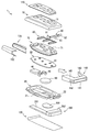
携帯機1は図1に示すように、上側ケース10、下側ケース20、回路基板30、アンテナ40、ターミナル50、電池60、弾性カバー70、セパレータ80、リリースボタン90、電池カバー100、上面プレート110、底面プレート120、サイドバンド130、サイドキャップ140、及びエマージェンシーキー200を備える。
As shown in FIG. 1, the portable device 1 includes an
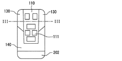
携帯機1は、これらの部材が組み合わされることで全体として、角部が丸められた扁平形状の略直方体を呈している。図2は、携帯機1の平面視における形状を概略的に表した図である。携帯機1は、平面視における形状が、長辺と短辺を有する長方形の角部が丸められた形状(以降、角丸長方形とする)となるように形成されている。なお、長辺と短辺を有する長方形とは、正方形以外の長方形に相当する。 As a whole, the portable device 1 has a flat, substantially rectangular parallelepiped shape with rounded corners by combining these members. FIG. 2 is a diagram schematically illustrating the shape of the portable device 1 in plan view. The portable device 1 is formed so that the shape in plan view is a shape in which a rectangular corner portion having a long side and a short side is rounded (hereinafter referred to as a rounded rectangle). A rectangle having a long side and a short side corresponds to a rectangle other than a square.
前述の本体部とは、上側ケース10、下側ケース20、回路基板30、アンテナ40、ターミナル50、電池60、弾性カバー70、セパレータ80、リリースボタン90、電池カバー100、上面プレート110、及び底面プレート120を上下方向に重ねて組み合わせた構造体である。
The above-described main body includes the
便宜上、以降では回路基板30に直交する方向のことを上下方向と記載する。回路基板30から下側ケース20に向かう方向が下方向であり、回路基板30から上側ケース10に向かう方向が上方向である。また、本体部の長辺に平行な方向を長手方向、短辺に平行な方向を短手方向と記載する。
For convenience, the direction perpendicular to the
前述のサイドカバーとは、サイドバンド130とサイドキャップ140である。サイドバンド130は図2に示すように、本体部を短手方向の両側から挟み込むように、本体部の両側面に取り付けられている。換言すれば、サイドバンド130は本体部が備える側面のうち、長手方向に延設された1対の側面(以降、長側面)のそれぞれに取り付けられている。
The aforementioned side covers are the
サイドキャップ140は、長手方向における本体部の一端に取り付けられた筒状の部材である。サイドバンド130とサイドキャップ140のどちらの部材も上側ケース10と下側ケース20とが互いに密着するように上下方向に挟み込む部材である。つまり、サイドバンド130と、サイドキャップ140は、上側ケース10と下側ケース20とが上下方向に分離することを抑制するように作用する。
The
また、サイドバンド130、サイドキャップ140は、上面プレート110及び底面プレート120とともに、携帯機1の外観意匠を構成する部材として機能する。エマージェンシーキー200は、車両ドアの鍵穴に差し込まれるキープレート部201と、その端部に設けられたキー把持部202を備える。
In addition, the
上側ケース10及び下側ケース20は、内部が中空となっている薄型の直方体を、厚み方向(換言すれば上下方向)に垂直な平面で2つに分割した形状である。上側ケース10と下側ケース20とは、厚み方向に重ねた状態で互いに嵌合するように構成されている。上側ケース10を下側ケース20に係止するための構造は、例えばフック式のスナップフィット等、周知の係止構造を採用することができる。なお、フック式のスナップフィットとは、一方のパーツに設けられたフックを、受け側に設けられた係合部(例えば凹部や貫通孔)に引っ掛けて機械的に保持する固定方式を示している。
The
例えば上側ケース10の所定の位置にフックを設け、当該フックを下側ケース20の所定の位置に設けられた係合部に引っ掛けることで、上側ケース10は下側ケース20に係止されればよい。当然、フックと係合部は、各部材において互いに対応する位置(換言すれば平面視において重なる位置)に設けられている。便宜上、上側ケース10と下側ケース20とを嵌合させた物体を、嵌合筐体と称する。嵌合筐体が請求項に記載の筐体に相当する。嵌合筐体の形状が、本体部の概略的な形状を提供する。
For example, if the
なお、上側ケース10と下側ケース20とが接合する部分(以降、ケース接合部)には、ゴム製のOリングが設けられている。Oリングは、上側ケース10に設けられていても良いし、下側ケース20に設けられていても良い。Oリングは、上側ケース10と下側ケース20とが嵌合する力によって圧縮されて、防水、防塵機能を提供する。
A rubber O-ring is provided at a portion where the
上側ケース10と下側ケース20とが一体となることで形成される嵌合筐体の内部には、回路基板30、弾性カバー70、セパレータ80、リリースボタン90、アンテナ40、ターミナル50、及び電池60が収容されている。具体的には、電池60は、下側ケース20と回路基板30との間に配置されている。アンテナ40、ターミナル50は、回路基板30の下側の面に搭載されている。
Inside the fitting housing formed by integrating the
弾性カバー70は、回路基板30の上側において、回路基板30の上面を覆うように配置されている。セパレータ80は、弾性カバー70と上側ケース10との間に配置されている。なお、リリースボタン90は、下側ケース20の側面に設けられたリリースボタン収容部22に取り付けられる。
The
上述した上側ケース10は、シリコンゴムなどを所定の材料を用いて実現されればよい。ここでは一例として上側ケース10はシリコンゴムを用いて実現されているものとする。上側ケース10の上面部には、複数の押力伝達部11が設けられている。複数の押力伝達部11はそれぞれ回路基板30に設けられているスイッチ素子31と、平面視において重なる位置に設けられている。各押力伝達部11は、ユーザの押下に伴って上下方向に動くように構成されている。
The
また、上側ケース10の側面部及び上面部には、上面プレート110、サイドバンド130、及びサイドキャップ140といった部材の取り付け位置を規定する凹部や凸部等が形成されている。つまり、上側ケース10の外側の面は、上面プレート110、サイドバンド130、及びサイドキャップ140の内側面の形状と適合するように形成されている。
Further, the side surface portion and the upper surface portion of the
上面プレート110、サイドバンド130、及びサイドキャップ140の位置決めのための凹部や凸部は、これらの部材が嵌合筐体に係止されて一体となるための部材として機能してもよい。なお、上面プレート110や、サイドバンド130、サイドキャップ140の内側面とは、携帯機1として完成された状態において外側から見えない側の面を指す。上側ケース10は、リリースボタン90の操作面91や係止部93が露出するように形成されている。
The concave portions and the convex portions for positioning the
下側ケース20は、例えばポリカーボネート(Polycarbonate:PC)樹脂や、ポリカABS樹脂等といった、適宜設計事項として要求される強度を提供する樹脂材料を用いて実現される。なお、ポリカABS樹脂は、PC樹脂とABS樹脂を混ぜた樹脂である。ABS樹脂は、アクリロニトリルとブタジエンとスチレンの共重合合成樹脂である。
The
下側ケース20の内側には、回路基板30及び電池60の支持および位置決めの機能を有する凸部や凹部が設けられている。また、下側ケース20の底部には、電池カバー100が嵌め込まれる開口部が設けられている。
On the inner side of the
さらに、下側ケース20の底部には、エマージェンシーキー200を収容するためのキー収容部21が形成されている。キー収容部21は主としてキープレート部201の形状に合致するように形成されている。下側ケース20の側面のうち、キープレート部201がキー収容部21に収容された場合にキー把持部202が位置する方の側面には、リリースボタン90の支持するためのリリースボタン収容部22が形成されている。
Further, a
リリースボタン90は当該リリースボタン収容部22に取り付けられる。エマージェンシーキー200が携帯機1に収容されている状態において、キー把持部202はリリースボタン90と当接する。
The
また、下側ケース20の外側の面には、底面プレート120や、サイドバンド130、サイドキャップ140の取り付け位置を規定する凹部や凸部等が形成されている。つまり、下側ケース20の外側の面は、底面プレート120や、サイドバンド130、サイドキャップ140の内側面の形状と適合するように形成されている。
Further, on the outer surface of the
回路基板30は、平面視にて略長方形の板状をなし、その上面に押しボタン式となる複数のスイッチ素子31が搭載されている。また、回路基板30の下面には、アンテナ40及びターミナル50が搭載されている。アンテナ40は、車両側装置と無線通信を実施するためのアンテナ素子である。ターミナル50は、電池60と回路基板30とを接続する端子である。
The
その他、回路基板30には、種々の制御を実行するための電子部品が実装されている。例えば、回路基板30には、復調回路や、変調回路、種々の演算処理を実行するCPU、RAM、ROMなどが実装されている。
In addition, electronic components for executing various controls are mounted on the
弾性カバー70は、吸湿し難く、かつ、弾力性を有する素材を用いて実現されている。例えば弾性カバー70は、シリコンなどを用いて実現されれば良い。弾性カバー70は、回路基板30の上面を被覆するとともに、下側ケース20と一体となるように形成されている。これにより弾性カバー70は、上側ケース10と下側ケース20とが接合する部分から入り込む水や異物が、弾性カバー70よりも内側(換言すれば回路基板30側)に進入することを防ぐ部材として機能する。
The
また、弾性カバー70の上面には、スイッチ素子31と重なる位置に、上方に突出した段差形状の突出段部71が形成されている。この突出段部71と前述の押力伝達部11によって、後述するボタン部111に対するユーザの押圧操作がスイッチ素子31に伝達される。また、ユーザがボタン部111を押下していない場合、突出段部71が備える弾性力によって押力伝達部11及びボタン部111は元の位置へと復元される。
Further, on the upper surface of the
弾性カバー70の上側に配置されるセパレータ80は、或る押力伝達部11に対してユーザが印加した力が、他の押力伝達部11に対応するスイッチ素子31に作用することを抑制するための部材である。セパレータ80は、突出段部71同士の間に(換言すればそれらを仕切るように)設置される。
The
リリースボタン90は、略棒状に形成された、エマージェンシーキー200を携帯機1から取り出すための取出ボタンとして機能する部材である。リリースボタン90の一端にはユーザによって操作されるための操作面91が設けられ、他端にはスプリング92が取り付けられている。操作面91は、サイドキャップ140に設けられた操作面用開口部142から外部に露出し、ユーザによって操作されるようになっている。
The
また、リリースボタン90には、エマージェンシーキー200が携帯機1に収容された状態を維持するための係止部93が設けられている。ユーザは操作面91を押下することで、エマージェンシーキー200に対する係止部93の位置をずらし、エマージェンシーキー200を携帯機1から取り出すことができる。リリースボタン90及びキー収容部21を含む構成が請求項に記載のキー保持機構に相当する。
The
スプリング92は、リリースボタン90の長手方向に伸縮する姿勢で取り付けられており、ユーザが操作したリリースボタン90を元の位置に戻す役割を担う。なお、後述するようにサイドキャップ140には操作面91が外部に露出させる開口部141が設けられており、当該開口部141によって操作面91は外部に露出される。
The
電池カバー100は、電池60を保護するための部材である。電池カバー100は、例えばPC樹脂などを用いて実現されれば良い。電池カバー100は、電池60の下側の面を保護するように下側ケース20の底部に取り付けられる。
The
上面プレート110は、上側ケース10の表面に取り付けられる板状部材である。上面プレート110は、例えばPA6などの種々のプラスチック材料を用いて実現されればよい。また、上面プレート110はシリコンゴムなどの弾性部材を用いて実現されても良い。
The
上面プレート110は、上側ケース10に上面に設けられた図示しない係止機構によって上側ケース10に取り付けられればよい。なお、他の態様として上面プレート110は、サイドバンド130やサイドキャップ140に挟み込まれることで上側ケース10の上面に固定されても良い。また、上面プレート110はキー把持部202に設けた差込スリットによって上側ケース10に取り付けられた状態が保持されてもよい。差込スリットは、上面プレート110の一端が挿入されるように形成された開口部である。
The
上面プレート110は、携帯機1の上側の外観面を提供する。上面プレート110には、平面視において押力伝達部11と重なる位置にボタン部111が形成されている。なお、押力伝達部11と重なる位置とは、スイッチ素子31や突出段部71と重なる位置にも相当する。各ボタン部111は、ユーザの押下に伴って上下方向に動くように構成されている。ボタン部111の表面には、当該ボタン部111を押下することによって実行される制御内容を表す図形や文字列が配置されている。
The
なお、ボタン部111は、押力伝達部11を露出させる開口部であってもよい。そのような態様によってもユーザはスイッチ素子31を押すことができるためである。仮にボタン部111を、押力伝達部11を露出させる開口部とする場合には、ボタン部111に代わって押力伝達部11の表面に、その部分をユーザが押下することによって実行される制御内容を表す図形や文字列が配置されているものとする。
The
底面プレート120は、下側ケース20の底面に取り付けられる板状部材である。底面プレート120は、例えばPA6などの種々のプラスチック材料を用いて実現されればよい。底面プレート120は、携帯機1の下側の外観面を提供する。底面プレート120の外側表面には所定の装飾が施されている。上面プレート110及び底面プレート120のそれぞれが請求項に記載の加飾プレートに相当する。以降では便宜上、上面プレート110と底面プレート120をまとめてプレート部材とも記載する。
The
底面プレート120は、下側ケース20に底部に設けられた係止機構によって下側ケース20に取り付けられればよい。なお、他の態様として底面プレート120は、サイドバンド130やサイドキャップ140に挟み込まれることで下側ケース20の底部に取り付けられても良い。また、底面プレート120は、上面プレート110と同様に、キー把持部202に設けられた差込スリットによって下側ケース20に取り付けられた状態が保持されてもよい。
The
サイドバンド130は、図3に示すように、上側ケース10と下側ケース20とを挟み込むように略U字型に形成されている。図中に符号131で指し示す部分は、上面プレート110及び下側ケース20のそれぞれに当接する部分(以降、当接部)を表している。
As shown in FIG. 3, the
このサイドバンド130は、嵌合筐体に取り付けられることによって、下側ケース20及び上側ケース10の側面部を覆い、かつ、上側ケース10と下側ケース20とが上下方向に分離しないように挟み込む部材として機能する。図3はサイドバンド130、上側ケース10、下側ケース20、上面プレート110、及び底面プレート120の位置関係を説明するための図である。図3において回路基板30等の図示は省略している。
The
このサイドバンド130は、PC樹脂やABS樹脂などを用いて実現されればよい。また、サイドバンド130の材質は金属であってもよい。サイドバンド130の内側面(つまり嵌合筐体と接する面)には、嵌合筐体に取り付けられた状態において位置ずれを防止するための凸部や凹部が設けられている。
The
サイドキャップ140は、図1中の白塗り矢印の方向にスライドさせることで、長手方向における嵌合筐体の一端(換言すれば側面)に装着される筒状の部材である。つまり、サイドキャップ140は、長手方向にスライドさせることで嵌合筐体から着脱可能に構成されている。
The
サイドキャップ140が取り付けられる端部は、本体部にエマージェンシーキー200が挿入された状態においてキー把持部202が位置する側の端部である。サイドキャップ140が取り付けられる端部が、請求項に記載の取付用端部に相当する。
The end portion to which the
筒状のサイドキャップ140の内側形状は、嵌合筐体の取付用端部の外側形状と適合するように形成されている。したがって、取付用端部に取り付けられたサイドキャップ140は、上側ケース10と下側ケース20を束ねるように機能する。つまり、サイドキャップ140は上側ケース10と下側ケース20の上下方向の動きを制限する。
The inner shape of the
サイドキャップ140は、エマージェンシーキー200が挿入されるための開口部141を備える。また、サイドキャップ140の短手方向の側面には、リリースボタン90の操作面91を露出される操作面用開口部142が設けられている。
The
さらに、本実施形態におけるサイドキャップ140は、嵌合筐体の長側面に沿うように形成されたサブバンド部143を有する。サブバンド部143は、上側ケース10と下側ケース20を挟み込むように略U字型に形成されており、前述のサイドバンド130と同様の機能を提供する。サブバンド部143は、サイドバンド130が有するバンド側端部122と当接し、サイドバンド130を嵌合筐体に係止する役割を担ってもよい。サイドキャップ140は、例えばPA6などの種々のプラスチック材料を用いて実現されればよい。もちろん、サイドキャップ140は金属を用いて実現されても良い。
Furthermore, the
エマージェンシーキー200は、キー収容部21及びリリースボタン90によって本体部に収容される。具体的には、キープレート部201がキー収容部21の内部に位置し、リリースボタン90が備える係止部93がキー把持部202に設けられたている凹部に引っかかることで本体部に固定される。
The
次に、上述した携帯機1の組立手順の一例を示す。まず、下側ケース20に電池60を配置した状態において、アンテナ40、ターミナル50が実装された回路基板30を下側ケース20に取り付ける。次に、弾性カバー70を下側ケース20に取り付け、リリースボタン90をリリースボタン収容部22に取り付ける。そして、弾性カバー70の上面にセパレータ80を配置し、上側ケース10を下側ケース20に嵌合させる。
Next, an example of the assembly procedure of the portable device 1 will be described. First, in a state where the
このようにして組み合わされてなる嵌合筐体の底面に電池カバー100を取り付け、さらに底面プレート120を取り付ける。また、上側ケース10の上に上面プレート110を被せる。そして、上述した一連の部材を組み付けた構造体に、上下方向と直交する方向からサイドバンド130及びサイドキャップ140を取り付ける。最後に、エマージェンシーキー200を挿入する。
The
なお、サイドキャップ140は、嵌合筐体とキー把持部202に挟まれるため、嵌合筐体と一体化するための連結係合を備える必要はない。もちろん、嵌合筐体との嵌合状態をより強固にするために、スナップフィット等の所定の係止機構が導入されていても良い。
Since the
以上の構成によれば、上側ケース10と下側ケース20とが分離する方向の動きが、サイドバンド130及びサイドキャップ140といったサイドカバーによって制限される。つまり、サイドカバーが嵌合筐体の耐落下性を補強する。
According to the above configuration, the movement in the direction in which the
そのため、特許文献1に開示されているようなサイドカバーを備えない構成(以降、従来構成)と比較して、上側ケース10を下側ケース20に係止するための嵌合爪に要求される強度等の制約を緩和することができる。また、嵌合爪周辺部分の強度に対する制約も緩和することができる。
Therefore, compared to a configuration without a side cover as disclosed in Patent Document 1 (hereinafter referred to as a conventional configuration), it is required for a fitting claw for locking the
つまり、以上の構成によれば、従来構成に比べて嵌合爪それ自体及び嵌合爪付近の部材に要求される大きさや強度といった構造上の制約が緩和されるため、嵌合爪を小さくしたり、上側ケース10などのケース部材の肉厚を薄くしたりできる。さらには、サイドカバーによって上側ケース10と下側ケース20との嵌合状態が保持されるため、上側ケース10と下側ケース20とを係止するための嵌合爪自体を備えない構成も採用できるようになる。その結果、嵌合筐体の小型化も可能となり、種々の意匠を採用できるようになる。つまり、意匠バリエーションを多様化することができる。
In other words, according to the above configuration, since the structural restrictions such as the size and strength required for the fitting claw itself and the member in the vicinity of the fitting claw are relaxed compared to the conventional configuration, the fitting claw can be made smaller. Or the thickness of the case member such as the
また、以上の構成によれば、上側ケース10と下側ケース20とがサイドカバーによって外側から挟み込まれるため、防水ゴム(具体的にはOリング)の圧縮率を一定の値に保持しやすい。その結果、耐久劣化を低減することができる。
Further, according to the above configuration, since the
さらに、上側ケース10と下側ケース20とが接合する部分(つまりケース接合部)が、サイドバンド130やサイドキャップ140に覆われる。そのため、ケース接合部が外部に露出する量が低減される。その結果、デザイン性として、ケース接合部に生じる段差を気にする必要性が低減される。
Furthermore, a portion where the
また、ケース接合部が外部に露出する部分は、携帯機1が備える側面のうち、サイドカバーが設けられていない部分に限定される。したがって、仮に上側ケース10と下側ケース20の表面にデザインとしてのしわ模様が形成されている場合であっても、ケース側面におけるシボ統一感を気にする必要性も低減される。
Moreover, the part which a case junction part exposes outside is limited to the part in which the side cover is not provided among the side surfaces with which the portable device 1 is provided. Therefore, even if a wrinkle pattern as a design is formed on the surfaces of the
さらに、筒状の部品(つまりサイドキャップ140)でリリースボタン90を覆うため、分解が複雑となり、回路基板30の改造などを抑止する効果が期待できる。また、回路基板30が複数の部材で覆われることになるため、静電気が回路基板30に悪影響を及ぼす可能性を低減することができる。
Furthermore, since the
また、上述した実施形態では、サイドカバーがサイドバンド130とサイドキャップ140の2種類のパーツに分割して実現される態様を採用とした。このような態様によれば、サイドキャップ140を嵌合筐体に取り付ける方向とは異なる方向からサイドバンド130を嵌合筐体に取り付けることができる。その結果、サイドカバーとしてアンダーカットとなる形状を採用することができ、見栄えを向上させたり、意匠設計の自由度を向上させたりすることが出来る。
Moreover, in embodiment mentioned above, the side cover was set as the aspect implement | achieved by dividing | segmenting into two types of parts, the
以上、本発明の実施形態を説明したが、本発明は上述の実施形態に限定されるものではなく、以降で述べる種々の変形例も本発明の技術的範囲に含まれ、さらに、下記以外にも要旨を逸脱しない範囲内で種々変更して実施することができる。 As mentioned above, although embodiment of this invention was described, this invention is not limited to the above-mentioned embodiment, The various modifications described below are also contained in the technical scope of this invention, and also in addition to the following However, various modifications can be made without departing from the scope of the invention.
なお、前述の実施形態で述べた部材と同一の機能を有する部材については、同一の符号を付し、その説明を省略する。また、構成の一部のみに言及している場合、他の部分については先に説明した実施形態の構成を適用することができる。 In addition, about the member which has the same function as the member described in the above-mentioned embodiment, the same code | symbol is attached | subjected and the description is abbreviate | omitted. In addition, when only a part of the configuration is mentioned, the configuration of the above-described embodiment can be applied to the other portions.
[変形例1]
上述した実施形態では、図3に示すようにサイドバンド130を、断面形状が丸みを帯びたU字型となるように形成されている態様を例示したが、これに限らない。図4に示すように嵌合筐体の断面が六角形となる場合には、その側面部の形状に合わせてサイドバンド130もまた断面形状がV字型となるような形状であってもよい。図4中において符号131Aで示す部分が、前述の当接部131と同様に、上側ケース10と下側ケース20の上下方向の動きを制限するように機能する。
[Modification 1]
In the above-described embodiment, as illustrated in FIG. 3, the
また、図5に示すように嵌合筐体の断面形状が八角形となる場合には、サイドバンド130もまたその側面部の形状に沿った形状となっていれば良い。つまり、サイドバンド130の断面形状は、嵌合筐体の側面形状に沿った形状となっていればよい。これらの種々の断面形状もU字型形状に相当する。換言すれば、請求項に記載のU字型形状とは、上側ケース10と下側ケース20を挟み込む形状に相当する。なお、図4、図5ではサイドバンド130が当接部131を備えない態様を例示しているが、もちろん当接部131を備えるように形成されていてもよい。
Moreover, as shown in FIG. 5, when the cross-sectional shape of a fitting housing | casing becomes an octagon, the
また、上面プレート110は、図6に示すようにサイドバンド130等を上から覆うように取り付けられていても良い。底面プレート120も同様である。さらに、サイドバンド130及びサイドキャップ140は、図7に示すように、プレート部材を介して嵌合筐体を挟みこむように形成されていても良い。その場合、プレート部材は、サイドバンド130等によって嵌合筐体に固定される。
Moreover, the
[変形例2]
上述した実施形態ではサイドバンド130を備える構成を開示したが、これに限らない。つまり、図8に示すように、サイドバンド130を備えなくともよい。
[Modification 2]
In the above-described embodiment, the configuration including the
[変形例3]
上述した実施形態では、携帯機1の概形として直方体の角部の丸みを抑えた形状を採用した態様を例示したがこれに限らない。例えば図9に示すように、長手方向の端部が半円状となるほど角部に丸みを付与してもよい。このような形状も、平面視における形状が長方形の角部を丸めた形状に含まれる。
[Modification 3]
In embodiment mentioned above, although the aspect which employ | adopted the shape which suppressed the roundness of the corner | angular part of a rectangular parallelepiped as an outline of the portable device 1 was illustrated, it is not restricted to this. For example, as shown in FIG. 9, the corners may be rounded as the ends in the longitudinal direction become semicircular. Such a shape is also included in a shape obtained by rounding corners of a rectangle in plan view.
[変形例4]
上側ケース10、下側ケース20、回路基板30、アンテナ40、ターミナル50、電池60、弾性カバー70、セパレータ80、リリースボタン90、及び電池カバー100を組みつけた部材(以降、共通内機モジュール)が、例えば耐落下性や防水性といった所定の基本性能を満たすように、上側ケース10、下側ケース20、及び弾性カバー70が設計されていても良い。
[Modification 4]
A member in which the
一般的には、外観形状や加飾部材の材料などといった意匠を構成する種々の要素の何れか1つが異なれば、落下時の衝撃の作用の仕方や防水性等が変わってくる。そのため、意匠バリエーション毎に各基本性能を確認する必要があり、開発工数がかかってしまう。 In general, if any one of various elements constituting the design such as the appearance shape and the material of the decorative member is different, the manner of impact at the time of dropping, waterproofness, and the like change. Therefore, it is necessary to confirm each basic performance for every design variation, and it takes a development man-hour.
そのような課題に対し、この変形例4に開示の構成によれば共通内機モジュールが基本性能を担保するため、上面プレート110や、底面プレート120、サイドバンド130、サイドキャップ140の材質や表面処理の変更に伴って、携帯機1全体としての基本性能が充足されているか否かを確かめる試験を省略することができる。換言すれば、共通内機モジュールを、種々のデザインを備える携帯機1の共通部品として流用することができるようになる。つまり、この変形例4の構成によれば、従来構成に比べて意匠バリエーションの拡充に伴う開発コストを抑制することができる。
In response to such a problem, according to the configuration disclosed in the fourth modification, the common internal unit module ensures basic performance, so that the materials and surfaces of the
また、この変形例4における構成によれば、サイドカバーやプレート部材は、携帯機1の意匠の自由度を提供したり、耐落下性や防水性等を補強したりするパーツとして機能する。さらに、この変形例4によれば、ユーザはサイドカバーを付け替えるだけで携帯機1の見栄えを変更できる。したがって、ユーザが携帯機1の外観を自分好みの外観にカスタマイズできるという点で、商品としての魅力(つまり商品性)を高めることができる。 Moreover, according to the structure in this modification 4, a side cover and a plate member function as parts which provide the freedom degree of the design of the portable device 1, or reinforce fall resistance, waterproofness, etc. Furthermore, according to the fourth modification, the user can change the appearance of the portable device 1 simply by changing the side cover. Therefore, the attractiveness (that is, the merchantability) of the product can be enhanced in that the user can customize the appearance of the portable device 1 to his / her favorite appearance.
なお、嵌合筐体の状態において所定の基本性能(例えば耐落下性や防水性)を満たすように設計された上側ケース10及び下側ケース20とは、従来構成における上側ケース及び下側ケースに相当する。
The
[変形例5]
図1では、上面プレート110において全てのスイッチ素子31に対応する位置にボタン部111を設けた態様を開示しているが、これに限らない。図10や図11に示すように、スイッチ素子31A〜Fの中には、ボタン部111を備えないスイッチ素子31が存在するように、上面プレート110を形成してもよい。
[Modification 5]
Although FIG. 1 discloses a mode in which the
なお、図10では一例として、スイッチ素子31A、31B、31C、31Dに対応する位置にはボタン部111を備える一方、スイッチ素子31E、31Eに対応する位置にはボタン部111を備えないように上面プレート110を形成した態様を開示している。また、図11では一例として、スイッチ素子31A、31B、31E、31Fに対応する位置にはボタン部111を備える一方、スイッチ素子31C、31Dに対応する位置にはボタン部111を備えないように上面プレート110を形成した態様を開示している。
In FIG. 10, as an example, the
このような思想を応用すれば、携帯機1を介してユーザが利用できる機能が異なる複数種類の携帯機1のそれぞれに対して一種類の共通内機モジュールを流用することができる。具体的には次の通りである。 If such an idea is applied, one type of common internal unit module can be used for each of a plurality of types of portable devices 1 having different functions that can be used by the user via the portable device 1. Specifically, it is as follows.
まず、共通内機モジュールには、複数のスイッチ機構を、複数種類のボタン配置バリエーションの何れにも対応できるように配置する。ここでのスイッチ機構とは、スイッチ素子31、突出段部71、及び、押力伝達部11を指す。そして、或る車両モデル用の携帯機1の上面プレート110は、共通内機モジュールが備える複数のスイッチ機構のうち、その車両モデルで使用されるスイッチ機構に対応する部分にのみ、ボタン部111を設けた構成とする。
First, in the common internal unit module, a plurality of switch mechanisms are arranged so as to be compatible with any of a plurality of types of button arrangement variations. Here, the switch mechanism refers to the
このような構成によれば、上面プレート110を付け替えるだけで、様々な車両モデルの携帯機1に対して1つの共通内機モジュールを流用することができる。具体的には、図10に示す上面プレート110を、図11に示す上面プレート110に置き換えるだけで、ユーザが携帯機1を介して使用可能な機能の組み合わせを、スイッチ素子31A、31B、31C、31Dのそれぞれに対応する機能の組み合わせから、スイッチ素子31A、31B、31E、31Fのそれぞれに対応する機能の組み合わせに変更することができる。
According to such a configuration, it is possible to divert one common internal unit module to the portable devices 1 of various vehicle models simply by changing the
[変形例6]
以上では、上側ケース10と上面プレート110とを別々の部材として取り扱う態様について開示したが、これに限らない。図12に示すように上側ケース10と上面プレート110とは、一体的に成形されていても良い。
[Modification 6]
In the above, although the aspect which handles the
1 携帯機、10 上側ケース(筐体)、20 下側ケース(筐体)、21 キー収容部(キー保持機構)、30 回路基板、40 アンテナ、50 ターミナル、60 電池、70 弾性カバー、80 セパレータ、90 リリースボタン(キー保持機構)、100 電池カバー、120 底面プレート(加飾プレート)、130 サイドバンド(サイドカバー)、140 サイドキャップ(サイドカバー) DESCRIPTION OF SYMBOLS 1 Mobile device, 10 upper case (casing), 20 lower case (casing), 21 key accommodating part (key holding mechanism), 30 circuit board, 40 antenna, 50 terminal, 60 battery, 70 elastic cover, 80 separator , 90 Release button (key holding mechanism), 100 Battery cover, 120 Bottom plate (decorative plate), 130 Side band (side cover), 140 Side cap (side cover)
Claims (3)
前記制御を実行するための機能が実装された回路基板(30)と、
前記回路基板に対して直交する方向である上下方向に分離するように構成された上側ケースと下側ケースとが組み合わされることによって実現されている筐体(10、20)と、
前記筐体の外側の側面に取り付けられてあって、前記上側ケースと前記下側ケースとを互いに密着させるサイドカバー(130、140)と、
前記車両に設けられた鍵穴に差し込まれるキープレート部と、ユーザによって把持されるためのキー把持部と、を備えた、前記車両のドアロックを機械的に施開錠するためのエマージェンシーキー(200)と、
前記エマージェンシーキーを着脱可能に保持するキー保持機構(21、90)と、を備え、
前記筐体は、上方から見た形状が長辺と短辺を有する長方形の角部を丸めた形状となるように形成されており、
前記キー保持機構は、前記筐体の長手方向に沿って形成されている、前記キープレート部を収容するキー収容部を備え、
前記サイドカバーとして、前記筐体の長手方向の一端である取付用端部に取り付けられてあって、前記上側ケースと前記下側ケースを束ねる筒状の部材であるサイドキャップを備え、
前記サイドキャップは、長手方向にスライドさせることで前記筐体の前記取付用端部から着脱可能に構成されており、
前記サイドキャップは、長手方向において前記筐体が備える2つ端部のうち、前記キー保持機構に前記エマージェンシーキーが装着されている状態において前記キー把持部が位置する方の端部に取り付けられてあって、
前記サイドキャップは、前記キー保持機構に前記エマージェンシーキーが装着された状態において、前記筐体と前記キー把持部に挟まれて、かつ、前記キー把持部によって前記筐体から長手方向にスライドしないように固定されていることを特徴とする携帯機。 A portable device that causes the device to perform at least control related to locking and unlocking of the door lock of the vehicle by wireless communication with a device provided in the vehicle,
A circuit board (30) mounted with a function for executing the control;
A housing (10, 20) realized by combining an upper case and a lower case configured to be separated in a vertical direction which is a direction orthogonal to the circuit board;
Side covers (130, 140) that are attached to the outer side surface of the housing and make the upper case and the lower case adhere to each other;
An emergency key (200) for mechanically locking and unlocking the door lock of the vehicle, comprising: a key plate portion to be inserted into a key hole provided in the vehicle; and a key grip portion to be gripped by a user. )When,
A key holding mechanism (21, 90) for detachably holding the emergency key,
The casing is formed so that the shape seen from above is a rounded corner of a rectangle having a long side and a short side,
The key holding mechanism includes a key accommodating portion that accommodates the key plate portion, which is formed along the longitudinal direction of the casing.
The side cover includes a side cap that is attached to an attachment end that is one end in the longitudinal direction of the housing and is a cylindrical member that bundles the upper case and the lower case.
The side cap is configured to be detachable from the mounting end of the housing by sliding in the longitudinal direction,
The side cap is attached to the end of the two ends of the casing in the longitudinal direction where the key grip is located in a state where the emergency key is attached to the key holding mechanism. There,
The side cap is sandwiched between the casing and the key gripping portion and is not slid in the longitudinal direction from the casing by the key gripping portion when the emergency key is mounted on the key holding mechanism. A portable device characterized by being fixed to the mobile phone.
前記サイドカバーとして、前記筐体を短手方向の両側から挟み込むように前記筐体の両側面に取り付けられた1対のサイドバンドを備え、
前記サイドバンドは、前記上側ケースと前記下側ケースとを挟み込むように、長手方向に直交する方向での断面形状がU字型に形成されていることを特徴とする携帯機。 In claim 1,
The side cover includes a pair of side bands attached to both side surfaces of the casing so as to sandwich the casing from both sides in the short direction,
The portable device according to claim 1, wherein the side band has a U-shaped cross-section in a direction perpendicular to the longitudinal direction so as to sandwich the upper case and the lower case.
前記下側ケースの下側の面には、底面プレート(120)が取り付けられており、
前記上側ケースの上側の面には、上面プレート(110)が取り付けられていることを特徴とする携帯機。 In claim 1 or 2 ,
The lower surface of the lower case is attached bottom surface plate (120),
Portable device on the upper surface of the upper case is characterized in that the upper surface plate (110) is attached.
Priority Applications (5)
| Application Number | Priority Date | Filing Date | Title |
|---|---|---|---|
| JP2016113857A JP6617648B2 (en) | 2016-06-07 | 2016-06-07 | Portable machine |
| US16/307,101 US10843660B2 (en) | 2016-06-07 | 2017-05-09 | Portable device |
| CN201780026765.4A CN109154164B (en) | 2016-06-07 | 2017-05-09 | Portable device |
| PCT/JP2017/017507 WO2017212847A1 (en) | 2016-06-07 | 2017-05-09 | Portable device |
| DE112017002841.8T DE112017002841T5 (en) | 2016-06-07 | 2017-05-09 | Portable device |
Applications Claiming Priority (1)
| Application Number | Priority Date | Filing Date | Title |
|---|---|---|---|
| JP2016113857A JP6617648B2 (en) | 2016-06-07 | 2016-06-07 | Portable machine |
Publications (3)
| Publication Number | Publication Date |
|---|---|
| JP2017218791A JP2017218791A (en) | 2017-12-14 |
| JP2017218791A5 JP2017218791A5 (en) | 2018-06-14 |
| JP6617648B2 true JP6617648B2 (en) | 2019-12-11 |
Family
ID=60578590
Family Applications (1)
| Application Number | Title | Priority Date | Filing Date |
|---|---|---|---|
| JP2016113857A Active JP6617648B2 (en) | 2016-06-07 | 2016-06-07 | Portable machine |
Country Status (5)
| Country | Link |
|---|---|
| US (1) | US10843660B2 (en) |
| JP (1) | JP6617648B2 (en) |
| CN (1) | CN109154164B (en) |
| DE (1) | DE112017002841T5 (en) |
| WO (1) | WO2017212847A1 (en) |
Families Citing this family (2)
| Publication number | Priority date | Publication date | Assignee | Title |
|---|---|---|---|---|
| JP7062429B2 (en) * | 2017-12-15 | 2022-05-06 | 株式会社Lixil | Remote control for electric lock of opening device |
| JP7098315B2 (en) * | 2017-12-15 | 2022-07-11 | 株式会社Lixil | Remote control for electric lock of opening device |
Family Cites Families (28)
| Publication number | Priority date | Publication date | Assignee | Title |
|---|---|---|---|---|
| DE19505190A1 (en) * | 1995-02-16 | 1996-08-22 | Marquardt Gmbh | Electronic key |
| US6460696B1 (en) * | 2000-08-17 | 2002-10-08 | Richard J. Meyer | Credit card holder with cards forming enclosing surfaces |
| JP4464053B2 (en) * | 2003-02-04 | 2010-05-19 | 株式会社東海理化電機製作所 | Portable machine |
| FR2851783B1 (en) * | 2003-02-28 | 2005-04-08 | Valeo Securite Habitacle Sas | KEY HOUSING |
| JP2005179942A (en) * | 2003-12-17 | 2005-07-07 | Denso Corp | Automobile wireless transmitter-receiver |
| DE202005004994U1 (en) | 2005-03-30 | 2005-05-25 | Hella Kgaa Hueck & Co. | Combined mechanical and radio key for vehicle includes locking component extending transversely with respect to recess for mechanical key |
| CN2823454Y (en) * | 2005-09-02 | 2006-10-04 | 许恒综 | Key box set |
| US7897888B2 (en) * | 2006-03-30 | 2011-03-01 | Strattec Security Corporation | Key fob device and method |
| JP2008008032A (en) | 2006-06-29 | 2008-01-17 | Denso Corp | Portable machine of electronic key system |
| JP2008266893A (en) * | 2007-04-16 | 2008-11-06 | Tokai Rika Co Ltd | Metallic decoration type electronic key |
| EP2239400B1 (en) * | 2009-04-08 | 2018-09-05 | Marquardt GmbH | Key for a motor vehicle |
| CN201442567U (en) * | 2009-07-03 | 2010-04-28 | 沈阳华晨金杯汽车有限公司 | Intelligent card structure for vehicle starting |
| DE102010014207B4 (en) | 2010-04-08 | 2015-11-05 | Continental Automotive Gmbh | key device |
| JP5445977B2 (en) * | 2011-08-10 | 2014-03-19 | 株式会社デンソー | Card key |
| CN202467351U (en) * | 2012-02-27 | 2012-10-03 | 国威科技有限公司 | Button mounting structure for key of vehicle engine lock |
| CN103375056A (en) * | 2012-04-22 | 2013-10-30 | 李尔汽车电子电器(上海)有限公司 | Remote control car key convenient for storing spare key |
| DE102012107950A1 (en) | 2012-08-29 | 2014-03-06 | Huf Hülsbeck & Fürst Gmbh & Co. Kg | Mobile identification transmitter for security system of motor vehicle i.e. motor car, has protection plate movably connected with housing using joint and form- and force-fittingly fastened to housing by holding element |
| CN203008545U (en) * | 2012-10-19 | 2013-06-19 | 北京经纬恒润科技有限公司 | Automobile key |
| CN104278887B (en) * | 2013-07-12 | 2016-12-28 | 上海海拉电子有限公司 | A kind of automobile key and installation method thereof |
| JP6489770B2 (en) * | 2013-09-26 | 2019-03-27 | 日新製鋼株式会社 | Stainless steel sheet having a small amount of elution in non-aqueous electrolyte environment, method for producing the same, and exterior member of non-aqueous electrolyte secondary battery |
| JP6270240B2 (en) * | 2013-10-30 | 2018-01-31 | 株式会社デンソー | Portable wireless key |
| JP6146619B2 (en) * | 2014-06-04 | 2017-06-14 | 株式会社デンソー | Electronic key for vehicle |
| US20150204108A1 (en) * | 2014-07-14 | 2015-07-23 | Lear Corporation | Key Fob Having Electrical Port Concealed by Removable Key |
| JP2016113857A (en) | 2014-12-18 | 2016-06-23 | 大倉工業株式会社 | Construction cover sheet |
| CN204663173U (en) * | 2015-05-29 | 2015-09-23 | 朱锡鑫 | A kind of sliding cover type automobile key containment vessel |
| CN204804485U (en) * | 2015-06-23 | 2015-11-25 | 余姚市阿波罗汽车配件有限公司 | Intelligent automobile key shell |
| CN204738608U (en) * | 2015-06-30 | 2015-11-04 | 黄山奥特斯电气股份有限公司 | Novel car key |
| US20180302788A1 (en) * | 2017-04-13 | 2018-10-18 | GM Global Technology Operations LLC | Backup vehicle entry and user authentication system |
-
2016
- 2016-06-07 JP JP2016113857A patent/JP6617648B2/en active Active
-
2017
- 2017-05-09 CN CN201780026765.4A patent/CN109154164B/en active Active
- 2017-05-09 WO PCT/JP2017/017507 patent/WO2017212847A1/en active Application Filing
- 2017-05-09 US US16/307,101 patent/US10843660B2/en active Active
- 2017-05-09 DE DE112017002841.8T patent/DE112017002841T5/en active Pending
Also Published As
| Publication number | Publication date |
|---|---|
| CN109154164A (en) | 2019-01-04 |
| JP2017218791A (en) | 2017-12-14 |
| US10843660B2 (en) | 2020-11-24 |
| DE112017002841T5 (en) | 2019-02-21 |
| WO2017212847A1 (en) | 2017-12-14 |
| US20190225187A1 (en) | 2019-07-25 |
| CN109154164B (en) | 2020-07-07 |
Similar Documents
| Publication | Publication Date | Title |
|---|---|---|
| JP6270240B2 (en) | Portable wireless key | |
| US7041924B2 (en) | Housing for an electronic key | |
| US5701355A (en) | Microphone for a two way radio | |
| KR101379576B1 (en) | Electronic key for vehicle | |
| KR101381007B1 (en) | Card key | |
| WO2015064033A1 (en) | Portable wireless key | |
| JPH098474A (en) | Case sealing structure and assembling method thereof | |
| JP6617648B2 (en) | Portable machine | |
| KR101975693B1 (en) | The fixing structure of the annular member and the electronic key | |
| JP2003201781A (en) | Waterproof structure of portable machine for keyless entry | |
| US20020154765A1 (en) | Mobile communication terminal | |
| JP2007299803A (en) | Shell of electric equipment | |
| JP5513346B2 (en) | Cover for mobile phone | |
| JP4946587B2 (en) | Portable machine | |
| JP2012036668A (en) | Portable wireless key | |
| JP2010077618A (en) | Electronic key | |
| CN211308493U (en) | Keyless entry and start system for vehicle | |
| KR100647981B1 (en) | structure for key pad rubber to fabricate of handphone | |
| KR20140001913U (en) | A Case for a portable electronics | |
| JP2008223376A (en) | Portable machine | |
| US10320059B2 (en) | Electronic device | |
| KR20210096516A (en) | Smartkey for vehicle | |
| CN110861610A (en) | Keyless entry and start system for vehicle |
Legal Events
| Date | Code | Title | Description |
|---|---|---|---|
| A521 | Request for written amendment filed |
Free format text: JAPANESE INTERMEDIATE CODE: A523 Effective date: 20180426 |
|
| A621 | Written request for application examination |
Free format text: JAPANESE INTERMEDIATE CODE: A621 Effective date: 20180426 |
|
| A131 | Notification of reasons for refusal |
Free format text: JAPANESE INTERMEDIATE CODE: A131 Effective date: 20190402 |
|
| A521 | Request for written amendment filed |
Free format text: JAPANESE INTERMEDIATE CODE: A523 Effective date: 20190529 |
|
| TRDD | Decision of grant or rejection written | ||
| A01 | Written decision to grant a patent or to grant a registration (utility model) |
Free format text: JAPANESE INTERMEDIATE CODE: A01 Effective date: 20191015 |
|
| A61 | First payment of annual fees (during grant procedure) |
Free format text: JAPANESE INTERMEDIATE CODE: A61 Effective date: 20191028 |
|
| R151 | Written notification of patent or utility model registration |
Ref document number: 6617648 Country of ref document: JP Free format text: JAPANESE INTERMEDIATE CODE: R151 |
|
| R250 | Receipt of annual fees |
Free format text: JAPANESE INTERMEDIATE CODE: R250 |
|
| R250 | Receipt of annual fees |
Free format text: JAPANESE INTERMEDIATE CODE: R250 |