JP6612367B2 - Safe assembly and installation of flywheel - Google Patents
Safe assembly and installation of flywheel Download PDFInfo
- Publication number
- JP6612367B2 JP6612367B2 JP2017567287A JP2017567287A JP6612367B2 JP 6612367 B2 JP6612367 B2 JP 6612367B2 JP 2017567287 A JP2017567287 A JP 2017567287A JP 2017567287 A JP2017567287 A JP 2017567287A JP 6612367 B2 JP6612367 B2 JP 6612367B2
- Authority
- JP
- Japan
- Prior art keywords
- rotor
- bearing
- flywheel
- flywheel device
- housing
- Prior art date
- Legal status (The legal status is an assumption and is not a legal conclusion. Google has not performed a legal analysis and makes no representation as to the accuracy of the status listed.)
- Active
Links
Images


Classifications
-
- H—ELECTRICITY
- H02—GENERATION; CONVERSION OR DISTRIBUTION OF ELECTRIC POWER
- H02K—DYNAMO-ELECTRIC MACHINES
- H02K7/00—Arrangements for handling mechanical energy structurally associated with dynamo-electric machines, e.g. structural association with mechanical driving motors or auxiliary dynamo-electric machines
- H02K7/02—Additional mass for increasing inertia, e.g. flywheels
- H02K7/025—Additional mass for increasing inertia, e.g. flywheels for power storage
-
- G—PHYSICS
- G05—CONTROLLING; REGULATING
- G05G—CONTROL DEVICES OR SYSTEMS INSOFAR AS CHARACTERISED BY MECHANICAL FEATURES ONLY
- G05G1/00—Controlling members, e.g. knobs or handles; Assemblies or arrangements thereof; Indicating position of controlling members
-
- H—ELECTRICITY
- H02—GENERATION; CONVERSION OR DISTRIBUTION OF ELECTRIC POWER
- H02K—DYNAMO-ELECTRIC MACHINES
- H02K15/00—Methods or apparatus specially adapted for manufacturing, assembling, maintaining or repairing of dynamo-electric machines
-
- H—ELECTRICITY
- H02—GENERATION; CONVERSION OR DISTRIBUTION OF ELECTRIC POWER
- H02K—DYNAMO-ELECTRIC MACHINES
- H02K15/00—Methods or apparatus specially adapted for manufacturing, assembling, maintaining or repairing of dynamo-electric machines
- H02K15/14—Casings; Enclosures; Supports
-
- H—ELECTRICITY
- H02—GENERATION; CONVERSION OR DISTRIBUTION OF ELECTRIC POWER
- H02K—DYNAMO-ELECTRIC MACHINES
- H02K7/00—Arrangements for handling mechanical energy structurally associated with dynamo-electric machines, e.g. structural association with mechanical driving motors or auxiliary dynamo-electric machines
- H02K7/003—Couplings; Details of shafts
-
- H—ELECTRICITY
- H02—GENERATION; CONVERSION OR DISTRIBUTION OF ELECTRIC POWER
- H02K—DYNAMO-ELECTRIC MACHINES
- H02K7/00—Arrangements for handling mechanical energy structurally associated with dynamo-electric machines, e.g. structural association with mechanical driving motors or auxiliary dynamo-electric machines
- H02K7/08—Structural association with bearings
- H02K7/086—Structural association with bearings radially supporting the rotor around a fixed spindle; radially supporting the rotor directly
- H02K7/088—Structural association with bearings radially supporting the rotor around a fixed spindle; radially supporting the rotor directly radially supporting the rotor directly
-
- H—ELECTRICITY
- H02—GENERATION; CONVERSION OR DISTRIBUTION OF ELECTRIC POWER
- H02K—DYNAMO-ELECTRIC MACHINES
- H02K7/00—Arrangements for handling mechanical energy structurally associated with dynamo-electric machines, e.g. structural association with mechanical driving motors or auxiliary dynamo-electric machines
- H02K7/08—Structural association with bearings
- H02K7/09—Structural association with bearings with magnetic bearings
-
- Y—GENERAL TAGGING OF NEW TECHNOLOGICAL DEVELOPMENTS; GENERAL TAGGING OF CROSS-SECTIONAL TECHNOLOGIES SPANNING OVER SEVERAL SECTIONS OF THE IPC; TECHNICAL SUBJECTS COVERED BY FORMER USPC CROSS-REFERENCE ART COLLECTIONS [XRACs] AND DIGESTS
- Y02—TECHNOLOGIES OR APPLICATIONS FOR MITIGATION OR ADAPTATION AGAINST CLIMATE CHANGE
- Y02E—REDUCTION OF GREENHOUSE GAS [GHG] EMISSIONS, RELATED TO ENERGY GENERATION, TRANSMISSION OR DISTRIBUTION
- Y02E60/00—Enabling technologies; Technologies with a potential or indirect contribution to GHG emissions mitigation
- Y02E60/16—Mechanical energy storage, e.g. flywheels or pressurised fluids
Description
本発明は、米国エネルギー省によって認められた契約OE−0000232に基づく政府支援によりなされた。政府は、本発明における特定の権利を有するものである。
本明細書は、エネルギー貯蔵全般に関連し、特に、フライホイールの組立、搬送、及び設置に関連する。
This invention was made with government support under Contract OE-0000232 approved by the US Department of Energy. The government has certain rights in the invention.
This description relates to energy storage in general, and in particular to flywheel assembly, transport, and installation.
多くのエネルギー源、特に、風力タービン及びソーラパネル等のクリーンエネルギー源では、経験した負荷と時間的に一致しないエネルギーを生成する。先進国の大部分では、エネルギー生成は経験した負荷に追従していて、エネルギーの必要に応じて供給される。高負荷の状況下では、ピーカジェネレータ及び熱発生器に対する自動生成制御(AGC:Automation Generation Control)の使用等の技術により、変化する高負荷に均衡する生成を行わせることができる。しかしながら、このような技術が利用可能であっても、エネルギー負荷に対応するためにエネルギー貯蔵が重要となる場合が往々にしてある。 Many energy sources, particularly clean energy sources such as wind turbines and solar panels, produce energy that does not match the experienced load in time. In most developed countries, energy generation follows the experienced load and is supplied as needed. Under high load conditions, generation such as the use of automatic generation control (AGC) for peaker generators and heat generators can be used to generate balanced to changing high loads. However, even when such techniques are available, energy storage is often important to cope with energy loads.
現在既存のエネルギー貯蔵システムは、すべて、何らかの欠点を有する。サイズ、価格、貯蔵効率、有効性、及び安全性のすべてがエネルギー貯蔵システムの設計時の懸案事項である。通常、小型、低価格、貯蔵の際のエネルギー投入と分配の際のエネルギー抽出の両方における損失低減、継続的動作の際の損失低減、及び安全な廃棄は、すべて、エネルギー貯蔵システムの好ましい特性である。 All currently existing energy storage systems have some drawbacks. Size, price, storage efficiency, effectiveness, and safety are all concerns when designing an energy storage system. Typically, small size, low cost, loss reduction in both energy input during storage and energy extraction during distribution, loss reduction during continuous operation, and safe disposal are all favorable characteristics of energy storage systems. is there.
ロータを組み込んだフライホイール機構は、回転運動エネルギーとしてエネルギーを貯蔵するエネルギー貯蔵システムの一種である。フライホイールロータは、荷重された、回転対称マスであり、BTB(Back-to-Back)インバータシステム等、AC−AC変換サブシステムを構成する変換器にそれ自身が電気的に接続されたモータ/発電機に対して直接又は間接的に物理的に連結されつつ回転する。貯蔵のための電力が受け取られると、ロータは、フライホイールロータの回転速度を増加させるように駆動される。その電力が取り出されるべき時、フライホイールロータは、モータ/発電機を駆動する。フライホイールロータが回転するスピードが速ければ速いほど、より多くのエネルギーを貯蔵することができる。フライホイールロータに貯蔵可能なエネルギー量は、ロータのマス、強度特性、繰り返し疲労特性、及び他の要因のうちの形状、の組み合わせによって決まる。通常、フライホイールの軸受及びサスペンションサブシステムは、摩擦、熱、及びその他の損失源によるエネルギー損失を最小限に抑えるように設計される。 A flywheel mechanism incorporating a rotor is a kind of energy storage system that stores energy as rotational kinetic energy. A flywheel rotor is a loaded, rotationally symmetric mass that is electrically connected to a converter that constitutes an AC-AC conversion subsystem, such as a BTB (Back-to-Back) inverter system. It rotates while being directly or indirectly physically connected to the generator. When power for storage is received, the rotor is driven to increase the rotational speed of the flywheel rotor. When that power is to be extracted, the flywheel rotor drives the motor / generator. The faster the flywheel rotor rotates, the more energy can be stored. The amount of energy that can be stored in the flywheel rotor is determined by a combination of rotor mass, strength characteristics, cyclic fatigue characteristics, and shape among other factors. Typically, flywheel bearings and suspension subsystems are designed to minimize energy loss due to friction, heat, and other loss sources.
現代のフライホイールシステムは、重くて複雑な機械であり、いくつかの繊細且つ慎重に調整された部品を含む。フライホイールシステムの組立、搬送、及び/又は設置は、大掛かりな仕事である。通常、フライホイールシステムは、設置場所で組み立てられてもよく、又は工場で組み立てられた後、設置場所に搬送されてもよい。 Modern flywheel systems are heavy and complex machines that include several delicate and carefully tuned parts. Assembling, transporting and / or installing a flywheel system is a major task. Typically, the flywheel system may be assembled at the installation site or may be transported to the installation site after being assembled at the factory.
フライホイールシステムが設置場所で組み立てられる場合、フライホイールシステムの組立に必要な装備及び専門技能が設置場所に搬送される必要がある。これには、法外なコストとスペースが求められる。フライホイールシステムが工場で組み立てられる場合、組立済みのフライホイールシステムは、設置場所に搬送される必要がある。組立済みのフライホイールシステムの搬送は、フライホイールシステムの内部部品が搬送中に動き回ってしまうと、組立済みのシステムに危険をもたらしてしまう。例えば、フライホイールロータが揺れて他の部品に当たり、ロータ又は他の部品を損傷してしまうかもしれない。また、ロータの動きにより、ロータの軸受によってかかる荷重がロータの重量より大きくなってしまうかもしれない。これにより潜在的に軸受を損傷してしまうかもしれない。
従って、本発明は、これらの考察およびその他に関して行われた。
When the flywheel system is assembled at the installation site, the equipment and specialized skills necessary to assemble the flywheel system need to be transferred to the installation site. This requires prohibitive cost and space. When the flywheel system is assembled at the factory, the assembled flywheel system needs to be transported to the installation site. Transfer of the assembled flywheel system poses a danger to the assembled system if the internal components of the flywheel system move around during transfer. For example, the flywheel rotor may swing and hit other parts, damaging the rotor or other parts. Also, due to the movement of the rotor, the load applied by the bearings of the rotor may become larger than the weight of the rotor. This can potentially damage the bearing.
Accordingly, the present invention has been made with respect to these considerations and others.
フライホイール装置は、エネルギーを貯蔵するフライホイールロータと、フライホイールを現場外で組み立て、安全に搬送させ、比較的少ないステップで設置させる追加構造とを含む。フライホイールは、エネルギーを貯蔵するロータを含み、ロータは、一次回転マスと、ロータの中心軸に沿って延びるジャーナルとを含む。フライホイールは、ロータを収容するハウジングも含み、ハウジングは、下部プレートと、上部プレートと、側壁とを含む。下部プレート及び上部プレートは、各々、ロータの中心軸に揃えられた孔を含む。フライホイールは、下部プレートと上部プレートの孔に実質的に埋め込まれる複数の軸受ハウジングをさらに含み、孔はロータの中心軸に揃えられている。フライホイールは、複数のポストも含み、フライホイールアセンブリの搬送中、ロータの動きを防ぐために、複数のポストは、ロータの一次回転マスに物理的に接触することができる。これらのポストのうちの一部又は全部は、設置中に、元の位置に戻されるか、又は取り除かれてもよく、それにより、ロータが自在に回転できるようになる。 The flywheel apparatus includes a flywheel rotor that stores energy and an additional structure that allows the flywheel to be assembled off-site, transported safely, and installed in relatively few steps. The flywheel includes a rotor that stores energy, and the rotor includes a primary rotating mass and a journal that extends along the central axis of the rotor. The flywheel also includes a housing that houses the rotor, the housing including a lower plate, an upper plate, and a sidewall. The lower plate and the upper plate each include a hole aligned with the central axis of the rotor. The flywheel further includes a plurality of bearing housings substantially embedded in the holes in the lower plate and the upper plate, the holes being aligned with the central axis of the rotor. The flywheel also includes a plurality of posts that can physically contact the primary rotating mass of the rotor to prevent movement of the rotor during transport of the flywheel assembly. Some or all of these posts may be returned to their original position or removed during installation, thereby allowing the rotor to rotate freely.
本発明の他の側面には、本明細書に記載の通り、搬送前後にフライホイールを組立及び設置する方法が含まれる。
ある実施形態において、フライホイールは、上方軸受に下向きのスラストを支持させることのできる上方軸受アセンブリを含む。上方軸受アセンブリは、上方軸受と、軸受ハウジングと、軸受係止キャップと、バックアップスラスト軸受と、キャップとを含む。バックアップスラスト軸受は、異常な垂直移動の場合に上向きのスラスト荷重を受容する。
Other aspects of the invention include a method of assembling and installing a flywheel before and after transport as described herein.
In certain embodiments, the flywheel includes an upper bearing assembly that allows the upper bearing to support a downward thrust. The upper bearing assembly includes an upper bearing, a bearing housing, a bearing locking cap, a backup thrust bearing, and a cap. The backup thrust bearing receives an upward thrust load in the case of abnormal vertical movement.
本開示の実施形態は、詳細な説明、別記のクレーム、及び添付の図(又は図面)によってさらに容易に明らかとなる、その他の効果及び特徴を有する。以下に、図の簡単な紹介を行う。
これらの図は、例示のみを目的として、本発明の実施形態を示している。当業者は、以下の議論より、本明細書に記載の発明の原則から逸脱することなく、本明細書に示される構造及び方法の代替実施形態が採用されてもよいことを容易に認識するであろう。 These figures depict embodiments of the present invention for purposes of illustration only. Those skilled in the art will readily appreciate from the following discussion that alternative embodiments of the structures and methods shown herein may be employed without departing from the principles of the invention described herein. I will.
フライホイールエネルギー貯蔵システム
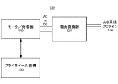
図1は、一実施形態に係る、フライホイールシステム100とも称されるフライホイールエネルギー貯蔵システム100のブロック図である。フライホイールシステム100は、フライホイール機構又は装置130、若しくは単にフライホイール130を含み、フライホイール130は、以下に説明するロータ及びハウジングと、モータ/発電機140と、電力変換器120と、AC又はDCであってもよい電力供給ライン150とを含む。例えば、電力供給ライン150は、従来の3位相60Hz ACラインであってもよい。ある実施形態において、電力変換器120は、入力された交流電流を、モータ/発電機140に受容可能な交流電流に変換する。或いは、他の実施形態において、変換器120は、モータ/発電機140からの交流電流を直流電流の出力に変換する。モータ/発電機140は、電気エネルギーと機械エネルギーとの間で変換を行い、エネルギーを、フライホイール130に貯蔵するか、又はフライホイール130から引き出すことができるようにする。モータ/発電機140は、例えば、シャフトを使用して直接に、又は、例えば、軸受に接続するスタブシャフトを使用して間接にフライホイール130に連結する。モータ/発電機140は、配線又はその他の電気連結部を介して、フライホイールシステム100の残りの部分に連結される。各部品を1つずつのみ図示したが、通常、実際のフライホイールシステム100は、各個別部品を複数含んでもよい。
フライホイールの構造
Flywheel Energy Storage System FIG. 1 is a block diagram of a flywheel
Flywheel structure
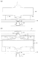
図2Aは、一実施形態に係る動作状態のフライホイール130の断面図である。即ち、図2Aのフライホイール130は、組立及び設置プロセス完了後の要素を示している。
FIG. 2A is a cross-sectional view of the
フライホイール130は、ハウジング201内にロータ205を含む。ハウジング201は、下部プレート221と、上部プレート223と、側壁225とを含む。ハウジング201は、通常、ロータ205を収容するような形状を有し、ロータ205が自由に回転できる十分な内部容量を提供する。ハウジング201は、円筒形状であってもよいが、その他の形状も可能である。上部プレート223及び下部プレート221は、各々、中心回転軸230に揃えられる少なくとも1つの孔を含む。中心回転軸230に揃えられた各孔には、実質的に、軸受ハウジングが埋め込まれる。下方軸受ハウジング209は、下方軸受207を収容し、上方軸受ハウジング217は、上方軸受215を収容する。上方軸受アセンブリ220とは、上方軸受215とともに上方軸受ハウジング217をいう。上方軸受アセンブリの代替実施形態については、図7を参照して後で説明する。
The
ロータ205は、エネルギーを運動エネルギーとして貯蔵するために使用される。ロータ205は、中心回転軸230を中心として実質的に回転対称である。ロータの一次回転マスの形状は、回転している間にロータにかかる回転力による応力の略均一な分布を確かなものにするのに役立つ。ロータ205は、2つのスタブシャフト、つまり、下方スタブシャフト227と上方スタブシャフト229に連結され、2つのスタブシャフトは、中心軸周りに自発的な回転を可能にさせながら、ロータを支持する軸受にロータを連結する。モータ/発電機の電磁ロータは、スタブシャフトの一方又は両方に取り付けられてもよい。モータ/発電機の目的は、ロータ205と電気ドメインとの間でエネルギーを伝達することである。本明細書において使用されるスタブシャフトという用語は、ロータ205の一方の側に連結する、比較的短いシャフトをいう。図2A及び図2Bに示される実施形態には、2つのスタブシャフトが採用されているが、他の実施形態において、単一のスタブシャフトが使用されてもよく、又は2つのスタブシャフトが使用されてもよい。スタブシャフト227及び229は、ロータの中心回転軸に沿って延びるジャーナルを介して、ロータ205に連結する。
The
ロータ205は、下方軸受207及び上方軸受215により、ハウジング201内の定位置に保持される。軸受207、215も、ロータ205に、できる限り少ない摩擦で自由に回転できるようにする。例えば、転がり玉軸受が使用されてもよい。この場合、軸受は、フライホイールハウジング201に対して物理的に取り付けられる外側リング(又はレース)と、ロータに連結されたシャフトに対して物理的に取り付けられる内側リング(又はレース)と、低い摩擦係数で外側リングに対して内側リングを回転させることができる、ボール等の複数の転がり要素とを含む。軸受は、各軸受ハウジング内に収容され、シャフトは、軸受の内側レース内に収容される。
The
ロータ205が受ける摩擦の量を低減するために、フライホイールシステム130は、ロータ205の重量の一部又は全部を荷重低減するオフローダ213を含む。結果として、オフローダ213は、軸受207の荷重を低減し、その結果として、軸受の摩擦モーメントを低減する。このように、軸受の摩擦で生じるロータによるエネルギー損失が実質的に低減される。オフローダ213は、実装によって、ロータ205を引き寄せるか、又は反発する磁界を生成することにより、ロータ軸受207が支持しなければならない重量を低減する。磁界は、例えば、電磁石内に適切に成形された電流を循環させることによって生成されてもよい。ロータ205が受ける磁力は、部分的に、オフローダ213の電磁石とロータ205間の距離に応じて決まる。したがって、電磁石とロータ205の間の距離を短くすることが有利である。しかしながら、オフローダとロータの間の距離を減少させると、特に搬送中に、ロータがオフローダに衝突する可能性が高くなる。
In order to reduce the amount of friction experienced by the
フライホイール機構130は、設置場所への搬送に先立って組み立てられてもよい。ロータ205の動き、軸受207、215への損傷、及びオフローダ213への損傷を防ぐために、フライホイール機構130は、搬送中、ロータの動きを制限するポスト203、219のうちの1つ以上を含む。ポストにより、さらに、いずれかの要素を損傷する著しいリスクを伴うことなく、オフローダ213及びロータ205を非常に近接して配置することが可能になる。さらに、オフローダ213をより近くに配置することによって、オフローダ213内の電磁石は、依然としてロータに同じ効果のある磁界を生じさせながら、より離して配置された場合に比べて、より小さく、又はより高い電力効率を達成することができる。本明細書の目的のために、ポストという用語は、ロータの一方向への移動を制限する構造的要素をいう。ある実施形態において、下部ポスト203又は上部ポスト219のみが存在し、他の実施形態においては、ポスト203及び219の両方が存在する。他の実施形態において、側壁225に固定された水平ポスト(図示せず)であってもよい。
The
図2Bは、一実施形態に係る搬送中のフライホイール130の断面図である。図2Bに示すように、下部ポスト203は、ロータ205に接触することにより、ロータの下方への動きを制限する。同様に、上部ポスト219は、ロータ205に接触することにより、ロータの上方への動きを制限する。ポスト及び軸受はともに、ロータの横方向の動きを制限する。図2Bに示すように、下部ポスト203は、ハウジング201の下部プレート221(又はその一部)に物理的に取り付けられてもよく、上部ポスト219は、上部プレートにおける孔(個別にはラベル付けしない)を通じて上部プレート223から取り外し可能(又は、少なくとも調整可能)であってもよい。他の実装において、上部ポスト及び下部ポストは、可動ポストが下部になり、取り付けられたポストが上部に取り付けられるように、逆にしてもよい。或いは、ポストの両セットが、可動であってもよい。ポストは、強度のある軽量な材料が好ましいが、任意の材料で作られてもよい。例えば、ポストは、とりわけ、アルミニウム、ゴム、又はプラスチックで作られてもよい。
FIG. 2B is a cross-sectional view of the
フライホイール130の設置中、上部ポスト219は、取り外されるか、一定距離持ち上げられ、ロータ205は、下部ポスト203から離れて上昇させられることにより、ロータ205は自由に回転できるようになる。一実施形態において、下方軸受ハウジング209にねじ止めされているバッキングプラグ211は、ロータ205を上昇させるために使用されてもよい。
フライホイール組立プロセス
During installation of the
Flywheel assembly process
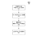
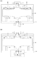
図3は、フライホイール130の組立プロセス300のフロー図である。図4−1(A)、図4−1(B)、図4−2(C)、および図4−2(D)は、組立の異なる段階におけるフライホイール130を示す。
FIG. 3 is a flow diagram of a
組立プロセス300は、ハウジング201の下部プレート221から開始する。ステップ301において、図4−1(A)に示されるように、下部ポスト203が下部プレート221に取り付けられる。例えば、下部ポスト203は、下部プレート221にボルト止めされる。或いは、リベット止め、溶接、又は接着等、他の技術を使用して、下部ポスト203を下部プレート221に物理的に取り付けてもよい。下部ポスト203が可動である場合、下部ポスト203は、下部プレート221の孔にねじ止めされる。
The
ステップ303において、図4−1(B)に示されるように、ロータ205が下部ポスト203上に配置される。ロータが2〜5トンの重量を有する場合、ロータを下部ポスト上に移動させるために、通常、クレーン又はその他の大型リフト機構が使用される。ロータは、応力及び貯蔵容量の問題を念頭において設計されるため、通常、ポストに対するロータの適切な配置を確実にするための明白な表面的特徴はロータにはない。しかしながら、ロータの一般的な形状を使用して、ハウジング201内のポストの配置を決定してもよい。例えば、円筒形ロータがポーラー軸に沿った曲線形状を有する場合、ロータの湾曲を使用して、最も滑りにくいポーラー軸に沿った箇所にポストを配置してもよい。
In
ロータのより適切な配置を達成するために、ロータは、ポスト上に一旦配置されると、ポストと正確に揃える粗調整プロセスを使用して再配置されてもよい。 To achieve a more appropriate placement of the rotor, the rotor may be repositioned using a coarse adjustment process that aligns precisely with the post once placed on the post.
ある実施形態において、図4−1(B)に示されるように、ロータ205は、ロータがポスト上に配置される時、既にスタブシャフト227及び229に連結されてもよい。他の実施形態において、スタブシャフト227及び229のロータ205への連結は、ステップ303の一部として実施される。
In some embodiments, as shown in FIG. 4B, the
ステップ305において、図4−2(C)に示されるように、下方軸受207、下方軸受ハウジング209、及びバッキングプラグ211が、ハウジング201に物理的に取り付けられる。例えば、下方軸受ハウジング209は、下部プレート221にボルト止めされる。或いは、リベット打ち、溶接、又は接着等、他の技術を使用して、下方軸受ハウジング209を下部プレート221に物理的に取り付けてもよい。そして下方軸受207は、下方軸受ハウジング209に挿入され、バッキングプラグ211は、下方軸受ハウジング209に取り付けられる。下方軸受207は、バッキングプラグ211によって支持され、バッキングプラグ211は、下方軸受ハウジング209にねじ止めされる。
In
ステップ307において、図4−2(D)に示されるように、上方軸受215、上方軸受ハウジング217、上部ポスト219、電磁オフローダ213、上部プレート223、ハウジング201の側壁225を含む上方アセンブリ410は、図4−2(C)に示される、部分的に組み立てられたフライホイールに物理的に取り付けられる。ロータ205は円筒形であり、引いては、ある実施形態において、ハウジング201が円筒形状であることも理解されうる。このような実施形態において、側壁225は、一つの円筒シェルであってもよい。通常、側壁225は、単一要素であってもよいし、又は、フライホイール130の両側を一緒に形成する、複数の取付要素であってもよい。上方サブアセンブリを組み立てるため、上方軸受ハウジング217が上部プレート223に物理的に取り付けられ、上方軸受215が上方軸受ハウジング217に挿入される。さらに、オフローダ213は、上部プレート223に物理的に取り付けられ、上部ポスト219は、上部プレート223内にねじ止めされる。一旦上方サブアセンブリが組み付けられると、側壁225が下部プレート221に物理的に取り付けられ、上部プレート223が側壁225に物理的に取り付けられる。
In
ハウジング201の下部プレート221、側壁225、及び上部プレート223の取り付けは、異なる物理的連結を使用してもよい。下部プレート221、側壁225、及び上部プレート223は、ねじ及び/又はリベットの使用、溶接、又は物理的取付を行うための他の任意の公知の機構を使用して、一緒に取り付けられてもよい。
The attachment of the
搬送中、ロータ205を適切な位置に保持するために、上部ポスト219は、ロータと物理的に接触するように下げられる。ロータを固定するために、上部ポストは、例えば、付与されるトルク下でねじを締めることにより、ロータに対して押し付けることができる。
フライホイール設置プロセス
During transport, the
Flywheel installation process
図5は、設置場所に到着した時点のフライホイール130の設置プロセス500のフロー図である。これらは、基本的には、フライホイール130を作動させるために実施されるステップである。図6A及び図6Bは、フライホイール130の設置プロセス500のあるステップを示している。
FIG. 5 is a flow diagram of a
ステップ501において、図6Aに示されるように、上部ポスト210は、ロータ205と物理的に接触しなくなるように、ロータ205から持ち上げられる。
In
一実施形態において、ステップ503に示され、図6Bに図示される通り、そして、バッキングプラグ211を上げることにより、ロータ205が下部ポスト203から上げられる。例えば、バッキングプラグ211がねじを使用して取り付けられている場合、バッキングプラグを下方軸受ハウジング209内にねじ込むことにより、下方軸受207を上昇させて、ロータ205を上昇させる。下部ポスト203からロータ205を上昇させるのではなく、下部ポスト203が取り外し可能であるか、少なくとも再配置可能である他の実施形態において、下部ポスト203は、代わりに、部分的又は完全に取り外され、ロータ205とはもはや接触しなくなってもよい。これらのプロセスの完了後のロータ205と上部219及び下部203のポストとの間の物理的距離は、実装によって変動することもある。
In one embodiment, the
ステップ503において、電磁オフローダ213が起動されて、軸受の重量を減らす。さらに、ハウジングが真空を保持することが可能である場合、付随の真空機械(図示せず)の作動によって真空が生成されてもよい。
フリップド軸受設計
In
Flip bearing design
図7は、フリップド軸受設計と称される、上方軸受アセンブリ700の一実施形態を簡略化した断面図である。上方軸受アセンブリ700は、上方軸受701が下方軸受と同様に上方へのスラスト荷重でなく、下方へのスラスト荷重を支持するという点で、図2Aを参照して説明した上方軸受アセンブリ220とは異なる。上方軸受701は図2Aの上方軸受215と同じ軸受であってもよいが、独自のフリップド軸受設計に起因して支持のされ方が違う。上述の通り、フライホイール130には、上方軸受アセンブリ220、フリップド軸受設計を有する上方軸受アセンブリ700、又は、本発明の主題の範囲及び要旨から逸脱することのない異なる設計の上方軸受アセンブリ等、の上方軸受アセンブリが含まれてもよい。
FIG. 7 is a simplified cross-sectional view of one embodiment of an
上方軸受アセンブリ700は、上方軸受701、軸受ハウジング703、軸受係止キャップ705、バックアップスラスト軸受707、及びキャップ709を含む。
The
軸受係止キャップ705は、上方軸受701をシャフト又はスタブシャフト711上にはめ合わせて保持する。本実施形態において、軸受ハウジング703は、下方から上方軸受701を支持する。
The
バックアップスラスト軸受707は、軸受係止キャップ705とキャップ709の間に配置される。これは、正常動作において、回転しないため、バックアップ軸受と称される。バックアップスラスト軸受707は、上方向へのスラストを回転エネルギーに変換することにより、損傷または封じ込みの問題を生じる可能性がある、スタブシャフト711からの垂直な上方向へのスラストを、吸収又は分散させる。このような異常な垂直移動は、例えば、搬送中のアクシデントにより、又は地震の事態の結果として発生し得る。搬送中、ロータは回転していないが、フライホイールの動作中に地震の事態又はその他の事態が発生すると、ロータ205は、回転する可能性が高いため、ロータの大きな回転エネルギーを吸収又は分散するためには、単にブッシング材でなく、バックアップ軸受が有利である。回転しているロータが従来の技術によるプラスチック又は金属で作成された静止ブッシングに接触する場合、一瞬の接触であったとしても、結果として生じる摩擦でブッシングを溶かす可能性が高い。
The
様々な実施形態では、フリップド軸受設計を特徴としてもよい。ある実施形態において、フライホイール130の上方軸受701及び下方軸受207は、一方向に高いスラストキャパシティを提供するアンギュラコンタクト玉軸受である。典型的には、アンギュラコンタクト玉軸受は、内側リング及び外側リング内に軌道を有し、内側リングと外側リングは軸受軸の方向に互いに相対的に変位する。これは、同時に起こる径方向の荷重と軸方向の荷重を収容するように設計されることを意味する。このような実施形態において、上方軸受701及び下方軸受は、下方方向に高いスラストキャパシティを提供するように搭載される。フリップド軸受設計を使用しないフライホイールの実施形態において、上方軸受701は、下方軸受207が下方へのスラストを支持しつつ、上方方向にスラストを支持する。即ち、互いに反転(フリップド)される。
Various embodiments may feature a flipped bearing design. In an embodiment, the
フリップド軸受設計を組み込んだフライホイールの実施形態は、図2A及び図2Bを参照して説明した、より簡易な設計に比べて、多数の利点を提供する。フリップド設計では両方の軸受が下方、すなわち、同一方向に向かうため、下方軸受を支持するばねを使用することにより、ロータ−ハウジング全体の軸の寸法の増加の差分を下方軸受台座で調整することができる。このように、オフローダにおける磁気ギャップの寸法は、ハウジングとロータの間の寸法変化の差分の下で、ほぼ不変である。上方軸受上への荷重は、磁気オフローディング制御システムによって設定及び制御される。下方軸受への荷重は、軸方向のプレロードばねによって完全に制御可能であるため、下方軸受があらゆる動作条件下で優れた疲労寿命を有するように簡単に保証することができる。そのように、たとえ、フライホイールの軸受に補修が必要である場合であっても、この補修には、フライホイールの連結を断って取り外す必要はなく、上部からアクセス可能な上方軸受701のみが関与する。
A flywheel embodiment incorporating a flipped bearing design provides a number of advantages over the simpler design described with reference to FIGS. 2A and 2B. In a flipped design, both bearings are directed downward, i.e. in the same direction, so that by using a spring that supports the lower bearing, the difference in the increase in the axial dimension of the entire rotor-housing can be adjusted at the lower bearing pedestal. it can. Thus, the size of the magnetic gap in the offloader is almost unchanged under the difference in dimensional change between the housing and the rotor. The load on the upper bearing is set and controlled by a magnetic offloading control system. Since the load on the lower bearing is fully controllable by an axial preload spring, it can easily be ensured that the lower bearing has an excellent fatigue life under all operating conditions. As such, even if the flywheel bearing requires repair, the repair does not require the flywheel to be disconnected and removed, only the
フリップド軸受設計は、オフローダを持ち上げるのに必要な力も低減する。例えば、オフローダがロータに+1000ポンドの重量を付与しなければならなかった上方軸受アセンブリ220が、フリップド軸受設計を使用した場合、ロータに−1000ポンドの重量を付与する。これにより、オフローダ213内の電磁石の制御をより容易にし、潜在的に、その電力消費とサイズを低減する。
The flipped bearing design also reduces the force required to lift the offloader. For example, an
稀な移動によって軸受に受ける損傷は、比較的より高価な主要軸受、すなわち、上方軸受701及び下方軸受ではなく、比較的より安価で交換の容易なバックアップ軸受707に衝撃を与えたり、又は損傷を与えたりする可能性がより高いであろう。
追加構成の考察
Damage to the bearings due to rare movements impacts or damages the relatively more expensive primary bearings, ie, the upper and
Additional configuration considerations
当分野の技術者は、本開示を熟読することで、本明細書に開示の原則を通じて、さらに追加の代替構造設計及び機能設計に想到するであろう。従って、特定の実施形態及び適用例について図示及び説明したが、開示の実施形態は、本明細書に開示の精密な構築及び部品に限定される物でない。別記のクレームに規定の要旨及び範囲から逸脱することなく、本明細書に記載の方法及び装置の配置、動作、及び詳細には、当分野の技術者にとって明らかとなる種々の修正、変更、及びバリエーションが加えられてもよい。
以下、参考態様の例を付記する。
1. 一次回転マスを有し、少なくとも1つのシャフトに接続された、エネルギーを貯蔵するロータと、
複数の孔を有して、各々、複数の孔のうちの1つが前記ロータの中心軸に揃えられる上部プレート及び下部プレートと、側壁とを含み、前記ロータを収容するハウジングと、
各々、前記ロータの前記中心軸に揃えられた各プレートの前記複数の孔のうちの1つに実質的に埋め込まれ、各々、少なくとも1つのシャフトに連結された軸受を含む、少なくとも1つの軸受ハウジングと、
前記フライホイールのアセンブリの搬送中、前記ロータの動きを防ぐために、前記ロータの前記一次回転マスと物理的に接触する複数のポストと、を備えるフライホイール装置。
2. 1.に記載のフライホイール装置において、
前記一次回転マスは、中心回転軸から極軸に沿って離れて外側に向かって広がるフライホイール装置。
3. 1.に記載のフライホイール装置において、
前記ロータに接続された前記少なくとも1つのシャフトは、各々、スタブシャフトであり、前記ロータの各側方には、対応するスタブシャフトに連結するジャーナルを有するフライホイール装置。
4. 1.に記載のフライホイール装置において、
前記複数のポストは、各々が前記上部プレートの前記孔のうちの1つを貫通する複数の上部ポストを含むフライホイール装置。
5. 1.に記載のフライホイール装置において、
前記複数のポストは、複数の下部ポストを含み、前記下部ポストは、各々、前記下部プレートに取り付けられるフライホイール装置。
6. 5.に記載のフライホイール装置において、
前記軸受のうちの下方軸受を上昇させるとともに、前記下部ポストから前記ロータをはずして上昇させるために、前記軸受ハウジングのうちの下方軸受ハウジングにねじ止めされたバッキングプラグをさらに備えるフライホイール装置。
7. 1.に記載のフライホイール装置において、
前記ハウジングは、前記ハウジング内に真空を生じさせるように密閉封止されるフライホイール装置。
8. 1.に記載のフライホイール装置において、
前記ロータは、強磁性材料で作成され、
前記プレートのうちの1つに取り付けられ、前記軸受のうちの下方軸受にかかる前記ロータの荷重を低減する電磁界を発生する磁気オフローダをさらに備えるフライホイール装置。
9. 8.に記載のフライホイール装置において、
前記磁気オフローダは、前記ハウジングの前記上部プレートに取り付けられるフライホイール装置。
10. 8.に記載のフライホイール装置において、
前記磁気オフローダは、前記ハウジングの前記下部プレートに取り付けられるフライホイール装置。
11. 1.に記載のフライホイール装置において、
上方軸受アセンブリをさらに備え、
前記上方軸受アセンブリは、
前記ロータの中心垂直軸に揃えられる前記上部プレートの孔に実質的に埋め込まれる軸受ハウジングと、
前記ロータに連結された上部シャフトに連結する上方軸受と、前記上方軸受は、
前記上方軸受の上方において、前記上方軸受を前記上部シャフト上に保持し、前記上方軸受上に載置することにより、前記フライホイールの動作中、前記上方軸受に下方へ向かうスラスト荷重を付与する軸受係止キャップとを備えるフライホイール装置。
12. 11.に記載のフライホイール装置において、
前記上方軸受は、アンギュラコンタクト軸受であり、下方へ向かうスラスト荷重を支持するように構成されるフライホイール装置。
13. 11.に記載のフライホイール装置において、
前記上方軸受アセンブリは、
前記軸受係止キャップの上方において、異常垂直移動の場合に上方へ向かうスラスト荷重を吸収するためのバックアップスラスト軸受と、
前記バックアップスラスト軸受の上方において、前記上方軸受アセンブリの上部を封止するキャップとをさらに備えるフライホイール装置。
14. フライホイール装置を組み立てる方法であって、
ハウジングの下部プレートに取り付けられる1つ以上のポスト上に、一次回転マスを含むロータを搭載し、
複数の孔を有して、各々、前記ロータの中心軸に揃えられた少なくとも1つの孔を含む上部プレート及び下部プレートと、側壁とを含むハウジングに、前記ロータを収容することを含む方法。
15. 14.に記載の方法において、
各前記プレートの前記ロータの前記中心軸に揃えられた前記孔に、軸受ハウジングを取り付けることと、
各前記軸受を前記軸受ハウジングのうちの1つに挿入することをさらに含む方法。
16. 14.に記載の方法において、
前記ロータは、強磁性材料で作成され、
前記ハウジングの前記上部プレートに、前記軸受のうちの下方軸受にかかる前記ロータの荷重を低減する磁界を発生する磁気オフローダを取り付けることをさらに含む方法。
17. 14.に記載の方法において、
前記ハウジングに前記ロータを収容することは、
前記下部プレートに前記側壁を取り付け、
前記側壁に前記上部プレートを取り付けることを含む方法。
18. 14.に記載の方法において、
前記ロータの各側方には、前記ロータの中心軸に沿って延び、各々、各軸受に前記ロータを連結する対応するスタブシャフトに嵌合するように構成されたジャーナルを有し、
各ジャーナルを前記対応するスタブシャフトに挿入することをさらに含む方法。
19. フライホイールシステムを設置する方法であって、
前記フライホイールシステムの軸受を上昇させることを含み、
前記フライホイールシステムは、
少なくとも1つのスタブシャフトに接続され、エネルギーを貯蔵するロータと、
前記ロータを収容し、複数の孔を有して、各々、前記ロータの中心軸に揃えられた少なくとも1つの孔を含む上部プレート及び下部プレートと、側壁とを含むハウジングと、
各々、前記ロータの前記中心軸に揃えられた各プレートの前記複数の孔のうちの1つに実質的に埋め込まれ、各々、少なくとも1つのスタブシャフトに連結された軸受を含む、少なくとも1つの軸受ハウジングと、
前記フライホイールシステムの搬送中、前記ロータの動きを防ぐために、前記ロータの前記一次回転マスと物理的に接触し、前記ハウジングの前記下部プレートに取り付けられた複数の下部ポスト、及び前記ハウジングの前記上部プレートに取り付けられた複数の上部ポストを含む複数のポストとを備え、
前記軸受を上昇させることは、
バッキングプラグを前記軸受ハウジングのうちの1つにねじ止めして、前記下部ポストが前記ロータの前記一次回転マスに物理的に接触しないように、前記ロータを前記下部ポストから離れるように上昇させ、
前記上部ポストを前記ロータの前記一次回転マスから取り外すことを含む方法。
Those skilled in the art, upon reading the present disclosure, will conceive additional alternative structural and functional designs through the principles disclosed herein. Thus, although particular embodiments and applications have been illustrated and described, the disclosed embodiments are not limited to the precise construction and components disclosed herein. The arrangement, operation, and details of the methods and apparatus described herein may be apparent to those skilled in the art from various modifications, changes, and without departing from the spirit and scope of the appended claims. Variations may be added.
Hereinafter, examples of reference embodiments will be additionally described.
1. A rotor for storing energy having a primary rotating mass and connected to at least one shaft;
A housing that includes a plurality of holes, each including an upper plate and a lower plate in which one of the plurality of holes is aligned with a central axis of the rotor, and a side wall;
At least one bearing housing comprising bearings each substantially embedded in one of the plurality of holes of each plate aligned with the central axis of the rotor and each coupled to at least one shaft When,
A flywheel apparatus comprising a plurality of posts in physical contact with the primary rotating mass of the rotor to prevent movement of the rotor during transport of the flywheel assembly.
2. 1. In the flywheel device described in
The primary rotary mass is a flywheel device that spreads outward from the central rotary axis along the polar axis.
3. 1. In the flywheel device described in
Each of the at least one shaft connected to the rotor is a stub shaft, and a flywheel device having a journal connected to a corresponding stub shaft on each side of the rotor.
4). 1. In the flywheel device described in
The plurality of posts is a flywheel device including a plurality of upper posts each passing through one of the holes of the upper plate.
5. 1. In the flywheel device described in
The plurality of posts includes a plurality of lower posts, and each of the lower posts is attached to the lower plate.
6). 5. In the flywheel device described in
A flywheel device further comprising a backing plug screwed to the lower bearing housing of the bearing housing in order to raise the lower bearing of the bearing and lift the rotor off the lower post.
7). 1. In the flywheel device described in
The flywheel device, wherein the housing is hermetically sealed so as to generate a vacuum in the housing.
8). 1. In the flywheel device described in
The rotor is made of a ferromagnetic material;
A flywheel device further comprising a magnetic offloader attached to one of the plates and generating an electromagnetic field that reduces a load on the rotor applied to a lower bearing of the bearings.
9. 8). In the flywheel device described in
The magnetic offloader is a flywheel device attached to the upper plate of the housing.
10. 8). In the flywheel device described in
The magnetic offloader is a flywheel device attached to the lower plate of the housing.
11. 1. In the flywheel device described in
Further comprising an upper bearing assembly;
The upper bearing assembly includes:
A bearing housing substantially embedded in a hole in the upper plate aligned with a central vertical axis of the rotor;
An upper bearing connected to the upper shaft connected to the rotor, and the upper bearing,
Above the upper bearing, the upper bearing is held on the upper shaft and placed on the upper bearing, thereby applying a downward thrust load to the upper bearing during operation of the flywheel. A flywheel device comprising a locking cap.
12 11. In the flywheel device described in
The upper bearing is an angular contact bearing, and is a flywheel device configured to support a downward thrust load.
13. 11. In the flywheel device described in
The upper bearing assembly includes:
Above the bearing locking cap, a backup thrust bearing for absorbing an upward thrust load in the case of abnormal vertical movement;
A flywheel device further comprising a cap for sealing an upper portion of the upper bearing assembly above the backup thrust bearing.
14 A method of assembling a flywheel device,
Mounting a rotor containing a primary rotating mass on one or more posts attached to the lower plate of the housing;
A method comprising: housing the rotor in a housing having a plurality of holes, each including an upper and lower plate including at least one hole aligned with a central axis of the rotor, and a sidewall.
15. 14 In the method described in
Attaching a bearing housing to the hole aligned with the central axis of the rotor of each plate;
The method further comprising inserting each said bearing into one of said bearing housings.
16. 14 In the method described in
The rotor is made of a ferromagnetic material;
The method further includes attaching a magnetic offloader that generates a magnetic field to reduce the load on the rotor applied to a lower bearing of the bearings to the upper plate of the housing.
17. 14 In the method described in
Housing the rotor in the housing,
Attaching the side wall to the lower plate;
Attaching the top plate to the sidewall.
18. 14 In the method described in
Each side of the rotor has a journal extending along the central axis of the rotor, each configured to fit a corresponding stub shaft that connects the rotor to each bearing,
The method further comprising inserting each journal into the corresponding stub shaft.
19. A method of installing a flywheel system,
Raising the bearing of the flywheel system,
The flywheel system
A rotor connected to at least one stub shaft and storing energy;
A housing containing the rotor and having a plurality of holes, each including an upper plate and a lower plate including at least one hole aligned with a central axis of the rotor, and a side wall;
At least one bearing each including a bearing substantially embedded in one of the plurality of holes of each plate aligned with the central axis of the rotor and each coupled to at least one stub shaft A housing;
In order to prevent movement of the rotor during transport of the flywheel system, a plurality of lower posts in physical contact with the primary rotating mass of the rotor and attached to the lower plate of the housing, and the housing of the housing With a plurality of posts including a plurality of top posts attached to the top plate;
Raising the bearing
Screwing a backing plug into one of the bearing housings, raising the rotor away from the lower post so that the lower post does not physically contact the primary rotating mass of the rotor;
Removing the upper post from the primary rotating mass of the rotor.
Claims (13)
前記ロータに連結されるシャフトと、
上部プレート及び下部プレートと、側壁とを含み、前記シャフトの中心軸に揃えられた孔が形成されるとともに、前記ロータを収容するハウジングと、
前記シャフトに連結された軸受を含み、前記ロータの前記1次回転マスが周りを回転する前記ロータの中心軸に揃えられた前記孔に実質的に埋め込まれる軸受ハウジングと、
前記フライホイールのアセンブリの搬送中の前記ロータの動きを防ぐために、前記フライホイールのアセンブリの搬送中、前記ロータの前記一次回転マスの前記下面に物理的に接触するように構成されている複数の下部ポストと、
前記1次回転マスを前記中心軸の周りに回転可能にする前記複数の下部ポストから前記ロータが離れて上昇させるように、前記複数の下部ポスト上で前記ロータを載置する搬送位置から、設置中に、前記軸受ハウジングを持ち上げるように構成されるリフト機構と、
前記フライホイールのアセンブリの搬送中の前記ロータの動きを防ぐために、前記フライホイールのアセンブリの搬送中、前記ロータの前記上面を物理的に接触するように構成される少なくとも一つの上部ポストと、を備え、
前記複数の下部ポストは、前記ハウジングに固定するように取り付けられ、
前記少なくとも一つの上部ポストは、前記1次回転マスを前記中心軸の周りに回転可能に、設置中、上昇させる、又は取り外されるように構成されるフライホイール装置。 An energy storing rotor having a primary rotating mass having an upper surface and a lower surface and connected to at least one shaft;
A shaft coupled to the rotor ;
A housing including an upper plate and a lower plate, and a side wall, wherein a hole aligned with a central axis of the shaft is formed, and housing the rotor ;
Comprising a bearing coupled to the shaft, and the bearing housing to be substantially embedded into the hole which is aligned with the central axis in said rotor said primary rotating mass of the rotor rotates around,
To prevent movement of the rotor during transport of the flywheel assembly, a plurality of configured to physically contact the lower surface of the primary rotating mass of the rotor during transport of the flywheel assembly. The bottom post ,
Installed from a transfer position on which the rotor is mounted on the plurality of lower posts such that the rotor is lifted away from the plurality of lower posts that allow the primary rotating mass to rotate about the central axis. A lift mechanism configured to lift the bearing housing ;
At least one upper post configured to physically contact the upper surface of the rotor during transport of the flywheel assembly to prevent movement of the rotor during transport of the flywheel assembly; Prepared ,
The plurality of lower posts are mounted to be secured to the housing;
Said at least one upper post, rotatably said primary rotating mass about said central axis, during installation, raise, or configured Ru flywheel device to be removed.
前記一次回転マスは、中心回転軸から外側に向かって、前記中心回転軸に対して水平面に沿って延在するフライホイール装置。 In the flywheel device according to claim 1,
Said primary rotating mass, toward the central rotational axis or al outer side, the flywheel device that Mashimasu extending along a horizontal plane relative to the central rotation axis.
前記ロータに接続される前記シャフトは、凹部を有するスタブシャフトであり、前記ロータは、前記ロータの前記中心回転軸に沿って突出し、前記スタブシャフトの前記凹部にはめ込まれて前記スタブシャフトに連結するジャーナルを有するフライホイール装置。 In the flywheel device according to claim 1,
The shaft connected to the rotor is a stub shaft having a recess , and the rotor protrudes along the central rotation axis of the rotor, and is fitted into the recess of the stub shaft to be coupled to the stub shaft. A flywheel device having a journal.
前記複数の下部ポストは、前記下部プレートに取り付けられるフライホイール装置。 In the flywheel device according to claim 1,
The plurality of lower posts are flywheel devices attached to the lower plate.
前記リフト機構は、軸受けハウジングにねじ止めされるバッキングプラグを含むフライホイール装置。 In the flywheel device according to claim 1,
The lift mechanism is a flywheel device including a backing plug screwed to a bearing housing .
前記ハウジングは、前記ハウジング内に真空を生じさせるように密閉封止されるフライホイール装置。 In the flywheel device according to claim 1,
The flywheel device, wherein the housing is hermetically sealed so as to generate a vacuum in the housing.
前記ロータは、強磁性材料で作成され、
前記プレートのうちの1つに取り付けられ、前記軸受にかかる前記ロータの荷重を低減する電磁界を発生する磁気オフローダをさらに備えるフライホイール装置。 In the flywheel device according to claim 1,
The rotor is made of a ferromagnetic material;
A flywheel device further comprising a magnetic offloader attached to one of the plates and generating an electromagnetic field that reduces the load on the rotor on the bearing.
前記磁気オフローダは、前記ハウジングの前記上部プレートに取り付けられるフライホイール装置。 In the flywheel device according to claim 7 ,
The magnetic offloader is a flywheel device attached to the upper plate of the housing.
前記軸受ハウジングは、前記ロータの下に配置される下方軸受ハウジングであるフライホイール装置。 In the flywheel device according to claim 1,
The said bearing housing is a flywheel apparatus which is a lower bearing housing arrange | positioned under the said rotor.
上方軸受アセンブリをさらに備え、
前記上方軸受アセンブリは、
前記ロータの中心垂直軸に揃えられる前記上部プレートの孔に実質的に埋め込まれる上方軸受ハウジングと、
前記ロータに連結された上部シャフトに連結する上方軸受と、
前記上方軸受の上方において、前記上方軸受を前記上部シャフト上に保持し、前記上方軸受上に載置することにより、前記フライホイール装置の動作中、前記上方軸受に下方へ向かうスラスト荷重を付与する軸受係止キャップと、を備えるフライホイール装置。 The flywheel device according to claim 9 ,
Further comprising an upper bearing assembly;
The upper bearing assembly includes:
An upper bearing housing substantially embedded in a hole in the upper plate aligned with a central vertical axis of the rotor;
An upper bearing coupled to the upper shaft coupled to the rotor;
Above the upper bearing, the upper bearing is held on the upper shaft and placed on the upper bearing, thereby applying a downward thrust load to the upper bearing during operation of the flywheel device. A flywheel device comprising a bearing locking cap.
前記上方軸受は、アンギュラコンタクト軸受であり、下方方向にかかる力に対抗するように構成されるフライホイール装置。 In flywheel device according to claim 1 0,
The upper bearing is an angular contact bearing, and is a flywheel device configured to resist a force applied in a downward direction.
前記上方軸受アセンブリは、
前記軸受係止キャップの上方において、異常垂直移動の場合に上方へ向かうスラスト荷重を吸収するためのバックアップスラスト軸受と、
前記バックアップスラスト軸受の上方において、前記上方軸受アセンブリの上部を封止するキャップとをさらに備えるフライホイール装置。 In flywheel device according to claim 1 0,
The upper bearing assembly includes:
Above the bearing locking cap, a backup thrust bearing for absorbing an upward thrust load in the case of abnormal vertical movement;
A flywheel device further comprising a cap for sealing an upper portion of the upper bearing assembly above the backup thrust bearing.
前記リフト機構は、前記軸受ハウジングにねじ止めされるフライホイール装置。 In the flywheel device according to claim 1,
The lift mechanism is a flywheel device screwed to the bearing housing.
Applications Claiming Priority (3)
| Application Number | Priority Date | Filing Date | Title |
|---|---|---|---|
| US201562185441P | 2015-06-26 | 2015-06-26 | |
| US62/185,441 | 2015-06-26 | ||
| PCT/US2016/039093 WO2016210176A1 (en) | 2015-06-26 | 2016-06-23 | Safe assembly and installation of a flywheel |
Publications (3)
| Publication Number | Publication Date |
|---|---|
| JP2018527518A JP2018527518A (en) | 2018-09-20 |
| JP2018527518A5 JP2018527518A5 (en) | 2019-04-11 |
| JP6612367B2 true JP6612367B2 (en) | 2019-11-27 |
Family
ID=57586466
Family Applications (1)
| Application Number | Title | Priority Date | Filing Date |
|---|---|---|---|
| JP2017567287A Active JP6612367B2 (en) | 2015-06-26 | 2016-06-23 | Safe assembly and installation of flywheel |
Country Status (7)
| Country | Link |
|---|---|
| EP (1) | EP3314731B1 (en) |
| JP (1) | JP6612367B2 (en) |
| KR (1) | KR102045340B1 (en) |
| CN (1) | CN107820662B (en) |
| CA (1) | CA2989308C (en) |
| PH (1) | PH12017550141A1 (en) |
| WO (1) | WO2016210176A1 (en) |
Cited By (1)
| Publication number | Priority date | Publication date | Assignee | Title |
|---|---|---|---|---|
| KR20220152614A (en) * | 2021-05-10 | 2022-11-17 | 현대일렉트릭앤에너지시스템(주) | Apparatus for reducing vibration for encoder of generator |
Families Citing this family (2)
| Publication number | Priority date | Publication date | Assignee | Title |
|---|---|---|---|---|
| CN107608369B (en) * | 2017-10-23 | 2023-10-03 | 沈阳航空航天大学 | Modularized inertia momentum wheel device for spacecraft attitude control experiment |
| US10982730B2 (en) | 2019-03-04 | 2021-04-20 | Saint- Augustin Canada Electric Inc. | Flywheel systems and related methods |
Family Cites Families (14)
| Publication number | Priority date | Publication date | Assignee | Title |
|---|---|---|---|---|
| CH459774A (en) * | 1965-09-16 | 1968-07-15 | Oerlikon Maschf | Vehicle with rotational energy storage, process for its operation and process for its production |
| SE323845B (en) * | 1968-01-19 | 1970-05-11 | Atlas Copco Ab | |
| DE2754623A1 (en) * | 1977-12-08 | 1979-06-13 | Maschf Augsburg Nuernberg Ag | Flywheel for driving rail or road vehicle - has stub shafts with intermediate hollow conical components coupled to flywheel at larger ends |
| JPS6064346U (en) * | 1983-10-11 | 1985-05-07 | 三菱電機株式会社 | flywheel device |
| US6029538A (en) * | 1997-09-08 | 2000-02-29 | Active Power, Inc. | Replaceable bearing cartridge assembly for flywheel energy system |
| US6064121A (en) * | 1998-02-27 | 2000-05-16 | Hamilton Sundstrand Corporation | Axially compact generator set and refrigeration system employing the same |
| US6664680B1 (en) * | 2000-12-20 | 2003-12-16 | Indigo Energy, Inc. | Flywheel device with active magnetic bearings |
| US6710489B1 (en) * | 2001-08-30 | 2004-03-23 | Indigo Energy, Inc. | Axially free flywheel system |
| US7197958B2 (en) * | 2003-08-27 | 2007-04-03 | Honeywell International, Inc. | Energy storage flywheel retention system and method |
| CN101924418A (en) * | 2009-12-22 | 2010-12-22 | 苏州菲莱特能源科技有限公司 | Flywheel energy-storing system in double-disc structure |
| CN201928127U (en) * | 2010-12-03 | 2011-08-10 | 天津荣亨集团股份有限公司 | Flywheel energy-storage device for double-stator alternating-current motor |
| CN201956795U (en) * | 2011-02-16 | 2011-08-31 | 东南大学 | Flywheel energy storage device |
| WO2014031905A1 (en) * | 2012-08-23 | 2014-02-27 | Amber Kinetics, Inc. | Apparatus and method for magnetically unloading a rotor bearing |
| EP3020122B1 (en) * | 2013-07-08 | 2020-11-18 | Saint-Augustin Canada Electric Inc. | Method for producing a kinetic energy storage system |
-
2016
- 2016-06-23 CN CN201680037320.1A patent/CN107820662B/en active Active
- 2016-06-23 CA CA2989308A patent/CA2989308C/en active Active
- 2016-06-23 JP JP2017567287A patent/JP6612367B2/en active Active
- 2016-06-23 WO PCT/US2016/039093 patent/WO2016210176A1/en active Application Filing
- 2016-06-23 KR KR1020187002601A patent/KR102045340B1/en active IP Right Grant
- 2016-06-23 EP EP16815335.1A patent/EP3314731B1/en active Active
-
2017
- 2017-12-13 PH PH12017550141A patent/PH12017550141A1/en unknown
Cited By (2)
| Publication number | Priority date | Publication date | Assignee | Title |
|---|---|---|---|---|
| KR20220152614A (en) * | 2021-05-10 | 2022-11-17 | 현대일렉트릭앤에너지시스템(주) | Apparatus for reducing vibration for encoder of generator |
| KR102535350B1 (en) | 2021-05-10 | 2023-05-26 | 에이치디현대일렉트릭 주식회사 | Apparatus for reducing vibration for encoder of generator |
Also Published As
| Publication number | Publication date |
|---|---|
| CA2989308C (en) | 2021-08-03 |
| CA2989308A1 (en) | 2016-12-29 |
| EP3314731A4 (en) | 2019-01-16 |
| CN107820662A (en) | 2018-03-20 |
| PH12017550141B1 (en) | 2018-06-11 |
| JP2018527518A (en) | 2018-09-20 |
| WO2016210176A1 (en) | 2016-12-29 |
| EP3314731B1 (en) | 2021-06-16 |
| EP3314731A1 (en) | 2018-05-02 |
| CN107820662B (en) | 2020-06-19 |
| KR20180021865A (en) | 2018-03-05 |
| PH12017550141A1 (en) | 2018-06-11 |
| KR102045340B1 (en) | 2019-11-15 |
Similar Documents
| Publication | Publication Date | Title |
|---|---|---|
| US10240660B2 (en) | Safe assembly and installation of a flywheel | |
| JP6612367B2 (en) | Safe assembly and installation of flywheel | |
| US8508064B2 (en) | Gondola with multi-part main shaft | |
| CA2775415C (en) | Direct drive wind turbine | |
| EP2199598B1 (en) | A hydroelectric turbine comprising a passive brake and method of operation | |
| US9048701B2 (en) | Passive magnetic bearings for rotating equipment including induction machines | |
| US7830055B2 (en) | Hybrid touchdown bearing system | |
| US9556851B2 (en) | System for reducing vibration in a wind turbine | |
| EP2484902A2 (en) | Pillow block for bed plate of wind turbine | |
| US10815969B2 (en) | Methods and apparatus for refurbishing wind turbine foundations | |
| US20130015825A1 (en) | Flywheel apparatus | |
| EP3349336B1 (en) | Maintaining double feed induction generator wye ring | |
| CN103580375A (en) | Wind turbine generator and maintenance of its main bearing | |
| US20060091741A1 (en) | Turbine generator vibration damper system | |
| US9627949B2 (en) | Method of vertically assembling a generator of a wind turbine | |
| CN105954029B (en) | Wind turbine transmission chain shafting dynamic misaligns vibration simulation system and analogy method | |
| JP2018527518A5 (en) | ||
| US20130340256A1 (en) | Bearing replacement method and tools for rotating machine | |
| US11885313B2 (en) | Shaftless generator for a fluid turbine | |
| Rowiński et al. | High speed electromechanical energy storage | |
| KR20120092383A (en) | Weightlessness generator for vertical wind power device | |
| KR20130032609A (en) | Flywheel using thrust rotation plate and flywheel energy storage device using the same | |
| WO2007145391A1 (en) | A wind power generating apparatus using magnetic force |
Legal Events
| Date | Code | Title | Description |
|---|---|---|---|
| A521 | Request for written amendment filed |
Free format text: JAPANESE INTERMEDIATE CODE: A523 Effective date: 20190301 |
|
| A621 | Written request for application examination |
Free format text: JAPANESE INTERMEDIATE CODE: A621 Effective date: 20190301 |
|
| A871 | Explanation of circumstances concerning accelerated examination |
Free format text: JAPANESE INTERMEDIATE CODE: A871 Effective date: 20190301 |
|
| A975 | Report on accelerated examination |
Free format text: JAPANESE INTERMEDIATE CODE: A971005 Effective date: 20190415 |
|
| A131 | Notification of reasons for refusal |
Free format text: JAPANESE INTERMEDIATE CODE: A131 Effective date: 20190423 |
|
| A521 | Request for written amendment filed |
Free format text: JAPANESE INTERMEDIATE CODE: A523 Effective date: 20190723 |
|
| TRDD | Decision of grant or rejection written | ||
| A01 | Written decision to grant a patent or to grant a registration (utility model) |
Free format text: JAPANESE INTERMEDIATE CODE: A01 Effective date: 20191001 |
|
| A61 | First payment of annual fees (during grant procedure) |
Free format text: JAPANESE INTERMEDIATE CODE: A61 Effective date: 20191030 |
|
| R150 | Certificate of patent or registration of utility model |
Ref document number: 6612367 Country of ref document: JP Free format text: JAPANESE INTERMEDIATE CODE: R150 |
|
| R250 | Receipt of annual fees |
Free format text: JAPANESE INTERMEDIATE CODE: R250 |
|
| R250 | Receipt of annual fees |
Free format text: JAPANESE INTERMEDIATE CODE: R250 |