JP6611691B2 - Method and apparatus for measuring outer shape of railway vehicle - Google Patents
Method and apparatus for measuring outer shape of railway vehicle Download PDFInfo
- Publication number
- JP6611691B2 JP6611691B2 JP2016198011A JP2016198011A JP6611691B2 JP 6611691 B2 JP6611691 B2 JP 6611691B2 JP 2016198011 A JP2016198011 A JP 2016198011A JP 2016198011 A JP2016198011 A JP 2016198011A JP 6611691 B2 JP6611691 B2 JP 6611691B2
- Authority
- JP
- Japan
- Prior art keywords
- linear laser
- railway vehicle
- outer shape
- vehicle
- laser beam
- Prior art date
- Legal status (The legal status is an assumption and is not a legal conclusion. Google has not performed a legal analysis and makes no representation as to the accuracy of the status listed.)
- Active
Links
Images


Classifications
-
- G—PHYSICS
- G01—MEASURING; TESTING
- G01B—MEASURING LENGTH, THICKNESS OR SIMILAR LINEAR DIMENSIONS; MEASURING ANGLES; MEASURING AREAS; MEASURING IRREGULARITIES OF SURFACES OR CONTOURS
- G01B11/00—Measuring arrangements characterised by the use of optical techniques
- G01B11/24—Measuring arrangements characterised by the use of optical techniques for measuring contours or curvatures
- G01B11/245—Measuring arrangements characterised by the use of optical techniques for measuring contours or curvatures using a plurality of fixed, simultaneously operating transducers
-
- G—PHYSICS
- G01—MEASURING; TESTING
- G01B—MEASURING LENGTH, THICKNESS OR SIMILAR LINEAR DIMENSIONS; MEASURING ANGLES; MEASURING AREAS; MEASURING IRREGULARITIES OF SURFACES OR CONTOURS
- G01B11/00—Measuring arrangements characterised by the use of optical techniques
- G01B11/24—Measuring arrangements characterised by the use of optical techniques for measuring contours or curvatures
- G01B11/25—Measuring arrangements characterised by the use of optical techniques for measuring contours or curvatures by projecting a pattern, e.g. one or more lines, moiré fringes on the object
- G01B11/2518—Projection by scanning of the object
- G01B11/2522—Projection by scanning of the object the position of the object changing and being recorded
Description
本発明は、鉄道車両の外形形状を光を用いて非接触で測定する鉄道車両の外形形状測定方法及び装置に関する。 The present invention relates to a method and apparatus for measuring the outer shape of a railway vehicle that measures the outer shape of the railway vehicle in a non-contact manner using light.
鉄道車両は、各鉄道事業者によって車両限界と呼ばれる車両が従うべき車体断面の大きさの限界範囲が定められており、各鉄道車両メーカは完成車両に対して車両限界を超過している部分が無いかの検査を行った後、出荷を行っている。
車両限界の検査方法としては、車両限界寸法を型取った枠(限界ゲージ)を車両の周囲に設置し、その中に車両を通過させながら、車両が枠に接触しないかを複数人の作業員で確認する方法が従来から行われている。
For railway vehicles, the limit range of the size of the cross-section of the car body that the vehicle should follow, which is called the vehicle limit, is defined by each railway operator, and each railway vehicle manufacturer has a portion that exceeds the vehicle limit for the completed vehicle. Shipments are made after checking for the presence.
As a vehicle limit inspection method, a frame (limit gauge) with a vehicle limit dimension is installed around the vehicle, and a plurality of workers check whether the vehicle does not touch the frame while passing the vehicle through it. The method of confirming with is conventionally performed.
車両が枠に接触した際は、車両を停止させ、複数人の作業員で接触状態の確認や、車両構体と台車の位置関係、車輪とレールの位置関係等の確認をし、原因調査を行う。このように、従来の方式は、車両毎に定められた枠の製造・設置作業に加えて複数人の作業員による検査作業の手間や作業時間が課題であり、これらを削減すること(測定自動化)が、車両製造のLT短縮、コスト削減の観点からも重要となっている。
車両限界検査を自動で行う方法として、特許文献1には、移動する車両の外周面に複数のレーザ光を線状に照射し、照射によって車両外周面に形成されたレーザ投影線(以下、光切断線)をカメラで検出することによって、検出された光切断線から車両の外形形状を算出し、車両限界超過の判定及び超過箇所を視認可能に表示する方法が開示されている。
When the vehicle touches the frame, stop the vehicle, check the contact state with multiple workers, check the positional relationship between the vehicle structure and the carriage, the positional relationship between the wheels and rails, and investigate the cause . As described above, the conventional method has a problem of labor and time of inspection work by a plurality of workers in addition to the manufacturing and installation work of the frame determined for each vehicle. ) Is also important from the viewpoint of shortening the LT for vehicle manufacturing and reducing costs.
As a method of automatically performing a vehicle limit inspection,
特許文献1に記載の方式では、レーザ光を用いることによって、非接触で車両の外形形状を測定することが可能である。
このとき、車両の塗装色によってレーザ光の反射率は大きく異なるため、塗装色の違いによる光切断線強度のばらつきが、光切断線検出における課題である。
In the method described in
At this time, since the reflectance of the laser light greatly varies depending on the paint color of the vehicle, the variation in the light section line intensity due to the difference in the paint color is a problem in the light section line detection.
そこで、本発明は、上述の点に鑑みてなされたものであり、レーザ光を用いて鉄道車両の外形形状測定を行う際に、車両の塗装色の影響を低減して、高速且つ高精度な外形形状の測定が可能となる方法を提供することを目的とする。 Therefore, the present invention has been made in view of the above points, and when measuring the outer shape of a railway vehicle using laser light, the influence of the paint color of the vehicle is reduced, and high speed and high accuracy are achieved. An object is to provide a method capable of measuring an outer shape.
上記課題を解決するために、本発明による、鉄道車両の外周面に複数の線状レーザ光を間断なく照射し、前記線状レーザ光の前記鉄道車両への照射位置、及び前記鉄道車両の外周面に照射された前記線状レーザ光の二次元平面投影像から、前記鉄道車両の外形形状を測定する鉄道車両の外形形状測定方法は、前記鉄道車両に前記線状レーザ光の強度を切り替えて照射しながら前記線状レーザ光強度の異なる複数の画像を撮影する撮影工程と、前記線状レーザ光強度の異なる複数の画像の中から、測定位置に最も適したレーザ光強度の撮影画像を選択する選択工程と、前記選択した撮影画像から前記鉄道車両の外形形状を算出する算出工程と、を含むことを特徴とする。 In order to solve the above-described problem, according to the present invention, a plurality of linear laser beams are irradiated on the outer circumferential surface of a railway vehicle without interruption, the irradiation position of the linear laser beams on the railway vehicle, and the outer circumference of the railway vehicle. A method for measuring the outer shape of a railway vehicle, which measures the outer shape of the railway vehicle from a two-dimensional planar projection image of the linear laser light irradiated on a surface, switches the intensity of the linear laser beam to the railway vehicle. Select a captured image of the laser beam intensity most suitable for the measurement position from the imaging step of capturing a plurality of images with different linear laser beam intensities while irradiating and the plurality of images with different linear laser beam intensities And a calculating step of calculating an outer shape of the railcar from the selected photographed image.
本発明によれば、車両の塗装色の影響を低減し、車両を移動させながら短時間で高精度な車両外形形状測定を行うことが可能となる。 ADVANTAGE OF THE INVENTION According to this invention, it becomes possible to reduce the influence of the paint color of a vehicle and to measure a vehicle external shape with high precision in a short time while moving a vehicle.
本発明は、単一波長もしくは複数波長の測定レーザ光強度を変化させながら取得した、複数の光切断画像から、適切なレーザ光強度、もしくは波長の画像を選択し、高精度な車両外形形状測定を行うことを可能にした車両外形形状測定方法及びその装置に関するものである。以下に、本発明の実施例を、図を用いて説明する。 The present invention selects a suitable laser beam intensity or wavelength image from a plurality of light cut images acquired while changing the measurement laser beam intensity of a single wavelength or a plurality of wavelengths, and highly accurate vehicle outer shape measurement. The present invention relates to a vehicle outer shape measuring method and apparatus capable of performing the above. Embodiments of the present invention will be described below with reference to the drawings.
<実施例1>
以下、本発明の実施例1に係る鉄道車両外形形状測定方法について図1〜図5を用いて説明する。
図1A、図1Bに、実施例1よる鉄道車両外形形状測定装置の構成の一例を示す。装置は、車両101の表面に線状のレーザ光102を照射し、車両101の表面に投影された線状レーザ光102(以下で光切断線)の撮影を行う複数台の光切断センサ103、当該複数台の光切断センサ103をレール上の車両を囲むように設置するセンサ架台104、車両の基準位置からの移動距離を測定する車両移動距離測定センサ105、及び測定処理機構110を備える。
<Example 1>
Hereinafter, the railway vehicle outer shape measurement method according to the first embodiment of the present invention will be described with reference to FIGS.
FIG. 1A and FIG. 1B show an example of the configuration of a railway vehicle outer shape measuring apparatus according to the first embodiment. The apparatus irradiates the surface of the
測定処理機構110は、上記線状レーザ光102の強度を一定時間毎に変化させるレーザ強度制御部111、及び前記強度を変化させた各線状レーザ光102の光切断線撮影画像の中から、測定位置に最も適したレーザ光の強度における光切断線画像を選択し、前記選択された光切断線画像から車両外形形状を算出する画像選択・形状算出部112、各構成機器の制御、及び車両限界超過有無の判定を行う全体制御部113、当該全体制御部113での処理結果を出力する結果出力部114から構成される。
光切断センサ103は、図2に示すように、線状レーザ光102を照射するレーザ光源ユニット201、及び車両101の表面に投影された線状レーザ光102を撮影する撮影ユニット202を搭載している。
The measurement processing mechanism 110 measures a laser intensity control unit 111 that changes the intensity of the
As shown in FIG. 2, the
撮影ユニット202は、撮像カメラ203、結像レンズ204、狭帯域フィルタ205から構成される。
撮像カメラ203の結像レンズ204はなるべく広角のものを用いることによって、個々の光切断センサの視野範囲を大きくし、少ない数の光切断センサで、車両外周の全範囲をカバーすることができる。
また、狭帯域フィルタ205によって各光切断センサが搭載するレーザ光の波長近傍の光のみを透過させる為、外乱光量を大幅に抑制することが可能となる。
The
By using an
In addition, since only the light in the vicinity of the wavelength of the laser light mounted on each light cutting sensor is transmitted by the
レーザ光源ユニット201から照射される線状レーザ光102の強度は、レーザ強度制御部によるレーザコントローラへの印加電圧制御によって、図3に示すように、撮影ユニット202の撮影レート:F(fps)と同期するように一定周波数:F(Hz)で数段階変化し、これをレーザ強度変調サイクル周期:T(s)で繰り返すように制御される。
The intensity of the
次に本発明を実施する際の測定の流れについて図4を用いて説明する。
測定開始に伴い、車両101は架台104の後方から架台に向かって移動を開始する(処理S401)。
移動を開始すると、車両101の移動距離をモニターして、車両が予め設定された測定開始位置に到達したか否かを判定し(処理S402)、車両が予め設定された測定開始位置まで移動した時点から、各光切断センサから照射される線状レーザ光の強度を、一定周波数:F(Hz)で数段階変化させ(処理S403)、撮影ユニット202によって、一定の撮影レート:F(fps)で光切断線の撮影を連続して行う(処理S404)。
Next, the flow of measurement when implementing the present invention will be described with reference to FIG.
With the start of measurement, the
When the movement is started, the moving distance of the
測定中は、車両移動距離測定センサ105によって絶えず車両101の移動距離をモニターし、車両が一定距離移動する毎に(処理S405)、撮影された光切断線から車両外形形状の算出(処理S406)、及び車両限界超過の有無(測定された車両外形の全座標点が車両限界を示す座標範囲内に有るか)の判定を行い(処理S407)、車両限界を超過していた場合、車両限界超過箇所の表示を行う(処理S408)。
上記S401〜S408までの処理を、車両101の測定位置が予め設定された測定終了位置に到達したと判断されるまで繰り返し(処理S409)、車両の全測定位置について車両限界超過箇所の表示を行う。
During the measurement, the moving
The processes from S401 to S408 are repeated until it is determined that the measurement position of the
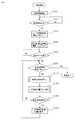
以下では、図4のS406に示される車両外形形状を算出する処理の流れについて、図5に示す車両外形形状算出サブルーチンフロー図を用いて説明する。
撮影された画像は、レーザ強度変調サイクル毎に照射するレーザ強度が数段階異なった画像がレーザ強度変調サイクル:T(s)毎に繰り返し含まれているため、同一レーザ強度変調サイクル内の画像を同一処理単位として処理を行う。
この場合、同一処理単位に含まれる画像数:Nは、レーザ強度変調サイクル周期:T(s)と撮影レート:F(fps)から、N=T×Fと算出できる。
Hereinafter, the flow of the process of calculating the vehicle outer shape shown in S406 of FIG. 4 will be described using the vehicle outer shape calculation subroutine flow chart shown in FIG.
Since the captured image includes an image in which the laser intensity irradiated for each laser intensity modulation cycle is different by several stages repeatedly every laser intensity modulation cycle: T (s), images within the same laser intensity modulation cycle are included. Processing is performed in the same processing unit.
In this case, the number of images included in the same processing unit: N can be calculated as N = T × F from the laser intensity modulation cycle period: T (s) and the imaging rate: F (fps).
処理を開始したら、測定レーザ光強度が異なる各撮影画像において、画素値が予め設定された閾値以上の画素を検出することによる光切断線画素の検出(処理SS501)、及び各撮影画像において光切断線として検出された画素の画素値平均値:M[i]の算出と前記算出された値のメモリへの格納を行い(処理SS502)、処理画像数:iのカウント値を更新する(処理SS503)。
次に処理画像数が同一処理単位数:Nに達したかの判定を行い(処理SS504)、処理画像数が同一処理単位数に達したら、SS502で算出した各撮影画像の検出画素値平均値: M[i]同士を比較し、平均値が最も高い光切断線の選択を行う。この際、光切断線の画素値が飽和していると算出される形状精度が悪くなる為、検出画素の画素値平均値が画素の飽和値に達しておらず、最も高い値であるか判定を行い(処理SS505)、SS505の判定条件を満たす場合は、画素値平均最大値:Mと、画素値平均が最大となる画像番号:ksを更新する(処理SS506)。
When processing is started, detection of light-section line pixels by detecting pixels whose pixel values are equal to or higher than a preset threshold in each captured image with different measured laser light intensities (processing SS501), and light cutting in each captured image The pixel value average value: M [i] of the pixels detected as a line is calculated and the calculated value is stored in the memory (processing SS502), and the processing image count: i is updated (processing SS503). ).
Next, it is determined whether the number of processed images has reached the same number of processing units: N (processing SS504). When the number of processed images reaches the same number of processing units, the detected pixel value average value of each captured image calculated in SS502: M [i] are compared with each other, and the light cutting line having the highest average value is selected. At this time, since the calculated shape accuracy deteriorates when the pixel value of the light section line is saturated, it is determined whether the pixel value average value of the detected pixels does not reach the pixel saturation value and is the highest value. (Processing SS505) When the determination condition of SS505 is satisfied, the pixel value average maximum value: M and the image number: ks at which the pixel value average is maximum are updated (Processing SS506).
次に平均値の比較を行った画像数:kを更新して(処理SS507)、比較画像数:kが同一処理単位数:Nに達したか判定を行い(処理SS508)、比較画像数:kが同一処理単位数:Nに達した時点で最も検出画素値平均値の高い画像番号:ksの光切断線を用いて車両外形形状の算出を行う(処理SS509)。
なお、上記で説明を行った車両外形形状の算出処理は、車両の移動終了後に行うことも可能である。
Next, the number of images that have been compared with the average value: k is updated (processing SS507), and it is determined whether the number of comparison images: k has reached the same number of processing units: N (processing SS508). When k reaches the same number of processing units: N, the outer shape of the vehicle is calculated using the light cutting line of the image number: ks having the highest detected pixel value average value (processing SS509).
Note that the vehicle outer shape calculation processing described above can also be performed after the vehicle has finished moving.
図4の変形例として、車両外形形状の算出処理を車両の移動終了後に行う流れについて図6を用いて説明する。
この場合、処理S601から処理S604までの処理は図4と同じであるが、図6においては、車両移動中に車両外形形状の算出を行わず、車両が測定終了位置に到達したと判定された後(処理S605)に、車両外形形状の算出(処理S607)、及び車両限界超過の判定(処理S608)の処理を全測定画像に対する処理が終了するまで行い(処理S606)、車両限界を超過したと判断された位置については、図4と同様に車両限界超過位置の表示を行う(処理S609)。
As a modification of FIG. 4, the flow of performing the vehicle outer shape calculation process after the movement of the vehicle will be described with reference to FIG. 6.
In this case, the processing from step S601 to step S604 is the same as that in FIG. 4, but in FIG. 6, it is determined that the vehicle has reached the measurement end position without calculating the vehicle outer shape while the vehicle is moving. After (processing S605), the calculation of the vehicle outer shape (processing S607) and the determination of exceeding the vehicle limit (processing S608) are performed until the processing for all measurement images is completed (processing S606), and the vehicle limit is exceeded. For the position determined to be, the vehicle limit excess position is displayed as in FIG. 4 (step S609).
本発明の実施例1に係る鉄道車両外形形状測定方法によれば、通常、測定レーザ光の反射光量は塗装色によって大きく影響を受けるが、本発明では測定に用いる光切断線のレーザ光強度を選択することができる為、車両の塗装色に対して、レーザ強度が適切でない(強すぎたり弱すぎたりする)ことで生じる形状精度の低下を低減し、高精度な形状測定を行うことが可能となる。 According to the railway vehicle outer shape measurement method according to the first embodiment of the present invention, the reflected light amount of the measurement laser light is usually greatly affected by the paint color, but in the present invention, the laser light intensity of the light cutting line used for measurement is determined. Since it can be selected, it is possible to reduce the deterioration of the shape accuracy caused by the inappropriate laser intensity (too strong or too weak) for the paint color of the vehicle, and to perform highly accurate shape measurement It becomes.
<実施例2>
以下、本発明の実施例2に係る鉄道車両外形形状測定方法について図7及び図8を用いて説明する。なお、実施例1と同一の構成については同一の符号を付し、その説明を省略する。
本実施例2では、図7に示す通り、カラーカメラのRGB(赤、緑、青色)各画素の波長帯に対応した複数波長を発生させることが可能なレーザ光源ユニット701を備え、撮像カメラにカラーカメラ702用いる点に特徴がある。
撮像カメラにカラーカメラを使用した場合、RGBの画素毎に、対応した波長帯の光を透過させるカラーフィルタが搭載されている為、RGBの各画素で、対応した波長帯以外の外乱光量を大幅に抑制でき、モノクロカメラを用いる場合と比べて、信号対雑音比(SN比)を上げられるという利点が生じる。
<Example 2>
Hereinafter, the railway vehicle outer shape measuring method according to the second embodiment of the present invention will be described with reference to FIGS. In addition, the same code | symbol is attached | subjected about the structure same as Example 1, and the description is abbreviate | omitted.
In the second embodiment, as shown in FIG. 7, a laser
When a color camera is used as the imaging camera, each RGB pixel is equipped with a color filter that transmits light in the corresponding wavelength band, so the amount of disturbance light outside the corresponding wavelength band is greatly increased in each RGB pixel. Compared with the case where a monochrome camera is used, there is an advantage that the signal-to-noise ratio (S / N ratio) can be increased.
複数波長光の発生方法としては、それぞれRGBに対応した波長のレーザを複数台用意してもよいし、RGBに対応した広い波長帯を有したレーザを使用しても問題は無い。
複数台のレーザ光源を用いる場合、複数のレーザ光源から照射された光の光路を光学素子で重ねて一本の線状ビームとして照射を行い、レーザ光の強度変調を行う際には、複数のレーザ光強度を同じタイミングで変化させる。なお、本発明を実施する際の測定の流れは図4や図6で示したものと同じである。
As a method of generating the multiple wavelength light, a plurality of lasers each having a wavelength corresponding to RGB may be prepared, or there is no problem even if a laser having a wide wavelength band corresponding to RGB is used.
When using a plurality of laser light sources, the optical paths of the light emitted from the plurality of laser light sources are overlapped with an optical element and irradiated as a single linear beam, and when performing intensity modulation of the laser light, The laser light intensity is changed at the same timing. The flow of measurement when implementing the present invention is the same as that shown in FIGS.
以下で撮影された光切断線から車両外形形状を算出する処理(図4のS406、図6のS607)について、図8に示す車両外形形状算出サブルーチンフロー図を用いて説明する。
実施例1と同様、撮影された画像は、レーザ強度変調サイクル毎に照射するレーザ強度が数段階異なった画像が繰り返し含まれているため、同一レーザ強度変調サイクル内の画像を同一処理単位として処理を行う。
The process of calculating the vehicle outer shape from the optical cutting line taken below (S406 in FIG. 4 and S607 in FIG. 6) will be described using the vehicle outer shape calculation subroutine flowchart shown in FIG.
As in the first embodiment, the captured image repeatedly includes images with different laser intensity levels for each laser intensity modulation cycle. Therefore, the images in the same laser intensity modulation cycle are processed as the same processing unit. I do.
処理を開始したら、測定レーザ光強度が異なる各撮影画像において、画素値が予め設定された閾値以上の画素を検出することによる光切断線画素の検出を行うが、本実施例では、複数波長の光による光切断線をカラーカメラで撮影している為、測定レーザ光強度が異なる各撮影画像をRGB成分画像に分解する(処理SS801)。
この際、赤色の波長の光による光切断線はR成分画像に強く現れ、緑色の波長の光による光切断線はG成分画像に強く現れ、青色の波長の光による光切断線はB成分画像に強く現れることは周知の通りである。
When the processing is started, the light cutting line pixels are detected by detecting pixels whose pixel values are equal to or higher than a preset threshold in each captured image having different measurement laser light intensities. Since a light cutting line by light is captured by a color camera, each captured image having a different measurement laser light intensity is decomposed into RGB component images (processing SS801).
At this time, a light cutting line due to light of red wavelength appears strongly in the R component image, a light cutting line due to light of green wavelength appears strongly in the G component image, and a light cutting line due to light of blue wavelength is the B component image. It is well known that it appears strongly in
次に、RGB各成分の画素値の和を算出し(処理SS802)、前記選択されたRGB成分の画素値の和に対して閾値判定を行い、光切断線画素を検出する(処理SS803)。
前記光切断線として検出された画素の画素値の和の平均値:M[i]の算出と前記算出値のメモリへの格納を行い(処理SS804)、処理画像数:iのカウント値を更新して(処理SS805)、処理画像数が同一処理単位数に達したかの判定を行う(処理SS806)。
Next, the sum of the pixel values of the RGB components is calculated (processing SS802), a threshold value is determined for the sum of the pixel values of the selected RGB components, and a light-section line pixel is detected (processing SS803).
The average value of the sum of the pixel values detected as the light cutting line: M [i] is calculated and the calculated value is stored in the memory (processing SS804), and the processing image count: the count value of i is updated. (Processing SS805), it is determined whether the number of processed images has reached the same number of processing units (Processing SS806).
処理画像数が同一処理単位数に達したら、SS804で算出した各撮影画像の検出画素値の平均値を比較し、最も平均値が高い光切断線の選択を行う。
実施例1と同様に、光切断線の画素値が飽和していると形状算出精度が悪くなる為、検出画素の画素値平均値が画素の飽和値に達しておらず、最も高い値であるか判定を行い(処理SS807)、SS807の判定条件を満たす場合は、画素値平均最大値:Mと画素値平均が最大となる画像番号:ksの更新を行う(処理SS808)。
次に、平均値の比較を行った画像数:kを更新し(処理SS809)、比較画像数:kが同一処理単位数:Nに達したか判定を行い(処理SS810)、比較画像数:kが同一処理単位数:Nに達した時点で最も検出画素平均値の高い画像番号:ksの光切断線を用いて車両外形形状の算出を行う(処理SS811)。
When the number of processed images reaches the same number of processing units, the average values of the detected pixel values of the captured images calculated in SS804 are compared, and the light cutting line with the highest average value is selected.
Similar to the first embodiment, when the pixel value of the light section line is saturated, the shape calculation accuracy is deteriorated. Therefore, the pixel value average value of the detection pixels does not reach the pixel saturation value, and is the highest value. If the determination condition of SS807 is satisfied, the pixel value average maximum value: M and the image number: ks at which the pixel value average is maximum are updated (processing SS808).
Next, the number of images for which the average values have been compared: k is updated (processing SS809), it is determined whether the number of comparison images: k has reached the same number of processing units: N (processing SS810), and the number of comparison images: When k reaches the same number of processing units: N, the outer shape of the vehicle is calculated using the optical cutting line of image number: ks having the highest detected pixel average value (processing SS811).
本発明の実施例2に係る鉄道車両外形形状測定方法によれば、光切断線の検出において、実施例1で説明した測定レーザ強度の変調に加えて、塗装色に対する測定レーザ波長の組合せも考慮することが可能である。
このため、例えば測定レーザ光波長に対する塗装色の反射率が非常に低く、測定レーザ光波長が一種類のみでは、レーザ強度を強くしても光切断線の検出強度が不十分であるような場合においても、塗装色の反射率がより高くなる波長のレーザ光を用いることによって、高精度な測定を行うことが可能となる。
According to the railway vehicle outer shape measurement method according to the second embodiment of the present invention, in addition to the modulation of the measurement laser intensity described in the first embodiment, the combination of the measurement laser wavelength with respect to the paint color is considered in the detection of the light cutting line. Is possible.
For this reason, for example, the reflectance of the coating color with respect to the measurement laser beam wavelength is very low, and the detection intensity of the light cutting line is insufficient even if the laser intensity is increased with only one type of measurement laser beam wavelength. In this case, it is possible to perform highly accurate measurement by using a laser beam having a wavelength at which the reflectance of the paint color becomes higher.
<実施例3>
以下、本発明の実施例3に係る鉄道車両外形形状測定方法について図9〜図13を用いて説明する。なお、実施例1及び2と同一の構成については同一の符号を付し、その説明を省略する。
<Example 3>
Hereinafter, a railway vehicle outer shape measuring method according to the third embodiment of the present invention will be described with reference to FIGS. In addition, about the structure same as Example 1 and 2, the same code | symbol is attached | subjected and the description is abbreviate | omitted.
図9A、図9Bに本実施例における鉄道車両外形形状測定装置の構成の一例を示す。
本実施例3では、鉄道車両側面の両端に亘って基準線となる線状の物体901を取付け、線状レーザ光102を、車両側面に加えて基準線となる線状の物体901の側面に照射することによって、図10Aに示す光切断センサの視野範囲1001において、図10Bに示す車両側面の光切断線1002と線状の物体901の光切断線1003を同時に検出する。
そして、車両の蛇行によって生じる光切断線1003の位置変動から、前記車両のレール基準位置からのずれ量を算出し、画像選択・形状算出部で算出した結果に対して前記算出したずれ量の補正を行う。
FIG. 9A and FIG. 9B show an example of the configuration of the railway vehicle outer shape measuring apparatus in the present embodiment.
In the third embodiment, a
Then, a deviation amount from the rail reference position of the vehicle is calculated from the position variation of the
基準線となる線状の物体901は、サブミリメートルオーダーの真直度が確保された物体が望ましいが、鉄道車両の全長は一般的に20m前後と長く、鉄道車両全長に亘って、サブミリメートルオーダーの真直度が確保された物体を製造するのは困難である。
基準線となる線状の物体自体が基準位置からうねっているような場合、線状の物体901による光切断線の位置変動が、基準線となる線状の物体901自体のうねり起因であるか、もしくは車両の蛇行起因であるかの区別を付けるのは困難である。
このため、本実施例では糸(もしくは紐)のように、張力をかけることによってうねりが生じない物質を用いる例について説明する。
The
When the linear object itself serving as the reference line undulates from the reference position, is the fluctuation in the position of the light cutting line caused by the
For this reason, in this embodiment, an example will be described in which a substance that does not generate undulation by applying tension, such as a thread (or string), is described.
図11に、実施例3に係る鉄道車両外形形状測定方法を実施する際の測定の流れを示す。
S1101からS1103までは図4のS401からS403と同じであるが、S1104の光切断線撮影の際、車両側面と線状の物体901の光切断線を同時に検出し、測定終了後に車両外形形状と車両蛇行量の算出・補正を行う。
FIG. 11 shows a measurement flow when the railway vehicle outer shape measurement method according to the third embodiment is performed.
Steps S1101 to S1103 are the same as steps S401 to S403 of FIG. Calculate and correct the amount of vehicle meandering.
以下で撮影された糸の光切断線から車両蛇行量を算出し、補正する処理(図11に示す処理S1108)の流れについて図12に示す車両蛇行量算出・補正サブルーチンフロー図を用いて説明する。 The flow of the process of calculating and correcting the vehicle meandering amount from the photographed light cutting line of the yarn (step S1108 shown in FIG. 11) will be described below using the vehicle meandering amount calculation / correction subroutine flowchart shown in FIG. .
実施例1及び2と同様に、撮影された画像は、レーザ強度変調サイクル毎に照射するレーザ強度が数段階異なった画像が繰り返し含まれているため、同一レーザ強度変調サイクル内の画像を同一処理単位として処理を行う。
この場合、全長に亘って同質且つ同色の糸を用いることによって、最も良いレーザ光強度を予め決定することができる為、同一処理単画像の中から予め決定したレーザ光強度の光切断線を選択して(処理SS1201)、画素値が予め設定された閾値以上の画素を検出することによる糸の光切断線の検出を行い(処理SS1202)、その後、SS1201とSS1202の処理を指定された全撮影画像に対して繰返す(処理SS1203)。
Similar to the first and second embodiments, the captured images repeatedly include images with different laser intensity levels for each laser intensity modulation cycle. Therefore, images in the same laser intensity modulation cycle are processed in the same way. Process as a unit.
In this case, since the best laser light intensity can be determined in advance by using the same quality and the same color thread over the entire length, a light cutting line having a predetermined laser light intensity is selected from the same processed single image. (Processing SS1201), detection of the light cutting line of the yarn is performed by detecting pixels whose pixel values are equal to or greater than a preset threshold value (Processing SS1202), and then all of the shootings specified with the processing of SS1201 and SS1202 It repeats with respect to an image (process SS1203).
処理SS1202で検出した糸の光切断線から糸の位置変動を算出する場合、光切断線データには、糸がレールに対して完全に平行に張られていないことによる、レールと鉛直方向の直線的な位置ずれ(糸の傾き成分)、及び車両の移動を加振源とする糸の振動(糸の振動成分)が重畳する為、これらによる糸の光切断線位置への影響を除去する必要が生じる。
糸の傾き成分は、レール方向の位置に対して線形である為、処理SS1202で検出した糸の光切断線のデータ列を、レール方向位置とレール鉛直方向位置を座標軸とするレール座標系データ列に変換し(処理SS1204)、前記データ列に対して直線式をフィッティングさせてデータ列における直線成分を算出し、前記データ列から、直線成分(糸の傾き成分)の除去を行う(処理SS1205)。
When calculating the position fluctuation of the yarn from the optical cutting line of the yarn detected in process SS1202, the optical cutting line data includes a straight line between the rail and the vertical direction due to the fact that the yarn is not stretched completely parallel to the rail. Since the positional displacement (yarn inclination component) and the vibration of the yarn (yarn vibration component) with the movement of the vehicle as the excitation source are superimposed, it is necessary to remove the influence of these on the position of the optical cutting line of the yarn Occurs.
Since the inclination component of the yarn is linear with respect to the position in the rail direction, the data sequence of the optical section line of the yarn detected in step SS1202 is used as the rail coordinate system data sequence having the rail direction position and the rail vertical direction position as coordinate axes. (Processing SS1204), a linear equation is fitted to the data string to calculate a linear component in the data string, and the linear component (yarn inclination component) is removed from the data string (processing SS1205). .
次に、糸の振動成分は一定時間周期で変動する成分を有している為、直線成分除去後の糸の光切断線データ列を、データのサンプリング時間と、レール鉛直方向位置を座標軸とする時間データ列に変換し(処理SS1206)、糸の振動周期が除去可能なローパスフィルタによって糸の振動成分を除去し(処理SS1207)、糸の傾き成分と糸の振動成分を除去した糸の光切断線データ列(糸の位置変動データ)を取得する。
上述のとおり、糸の光切断線のデータは、予めレーザ光強度を決定しておくことによって一定時間間隔(レーザ強度変調サイクル周期間隔)で取得したデータとなっている為、容易にフィルタリング処理を行うことが可能である。
Next, since the vibration component of the yarn has a component that fluctuates at a constant time period, the data section of the yarn after cutting the linear component is used as the coordinate axis with the data sampling time and the rail vertical position as the coordinate axes. Conversion into a time data string (processing SS1206), the vibration component of the yarn is removed by a low-pass filter capable of removing the vibration cycle of the yarn (processing SS1207), and the optical cutting of the yarn from which the inclination component and the vibration component of the yarn are removed A line data string (yarn position variation data) is acquired.
As described above, since the data of the light cutting line of the yarn is data obtained at a predetermined time interval (laser intensity modulation cycle period interval) by determining the laser light intensity in advance, the filtering process can be easily performed. Is possible.
また、糸の振動周期は糸を張る際の張力、及び糸の線密度の値から式(1)で表すことができ、実際の振動は複数の次数のモードが合成されたものであるが、振動周波数が最も低い一次モードよりも大きい振動数を除去するローパスフィルタを適用することによって、各モードの振動成分についても除去することが可能である。
![]()
最後に、処理SS1207で取得したレール鉛直方向における糸の位置変動データ列を各光切断センサによる車両外形形状データに対して加減算することによって、車両の蛇行による車両外形形状誤差の補正を行う(処理SS1208)。
Further, the vibration cycle of the yarn can be expressed by the formula (1) from the tension when the yarn is stretched and the value of the linear density of the yarn, and the actual vibration is a combination of modes of a plurality of orders. By applying a low-pass filter that removes a frequency greater than that of the primary mode having the lowest vibration frequency, it is possible to remove vibration components of each mode.
![]()
Finally, the vehicle outer shape error due to the meandering of the vehicle is corrected by adding / subtracting the yarn position variation data string in the rail vertical direction acquired in step SS1207 to the vehicle outer shape data by the respective light cutting sensors (processing). SS1208).
次に、糸の位置変動測定データ例について図13を用いて説明する。図13は車両全長に亘って取得した糸の位置変動データのうち、一部の区間のデータのみを抜き出したものである。
図13(a)のデータ列1301は、検出した糸の光切断線のデータ列を、レール方向位置とレール鉛直方向位置を座標軸とするレール座標系に変換したものであり、図13(b)のデータ列1302は、図13(a)の1301に対して直線式をフィッティングさせて得られた直線成分(糸の傾き成分)を示している。
Next, an example of yarn position variation measurement data will be described with reference to FIG. FIG. 13 shows only part of the data extracted from the position variation data of the yarn acquired over the entire length of the vehicle.
The
図13(a)の1301から図13(b)の1302の成分を除去することによって図13(c)の1301を得ることが出来、図13(c)の1301からローパスフィルタによって、糸の振動成分である図13(d)の1303を除去することによって、車両蛇行による糸の位置変動データ列である図13(e)の1301を得ることができる。
本発明の実施例3に係る鉄道車両外形形状測定方法によれば、車両外形形状を測定するレーザ光を用いて前記線状の物体901の位置ずれ量を車両側面と同時に測定する為、車両側面の測定断面と同断面における位置ずれ量を高精度に検出することができ、車両外形形状の測定精度を向上させることが可能となる。
1301 in FIG. 13B can be obtained by removing the
According to the railway vehicle outer shape measuring method according to the third embodiment of the present invention, the positional deviation amount of the
なお、本発明は上記した実施例に限定されるものではなく、様々な変形例が含まれる。例えば、上記した実施例は本発明を分かりやすく説明するために詳細に説明したものであり、必ずしも説明した全ての構成を備えるものに限定されるものではない。
また、ある実施例の構成の一部を他の実施例の構成に置き換えることが可能であり、また、ある実施例の構成に他の実施例の構成を加えることも可能である。
さらに、各実施例の構成の一部について、他の構成の追加・削除・置換をすることが可能である。
In addition, this invention is not limited to an above-described Example, Various modifications are included. For example, the above-described embodiments have been described in detail for easy understanding of the present invention, and are not necessarily limited to those having all the configurations described.
Further, a part of the configuration of one embodiment can be replaced with the configuration of another embodiment, and the configuration of another embodiment can be added to the configuration of one embodiment.
Furthermore, it is possible to add, delete, and replace other configurations for a part of the configuration of each embodiment.
101 鉄道車両
102 線状のレーザ光
103 光切断センサ
104 センサ架台
105 車両移動距離測定センサ
201 レーザ光源ユニット
202 撮影ユニット
203 撮像カメラ
204 結像レンズ
205 狭帯域フィルタ
701 複数波長レーザ光源ユニット
702 カラーカメラ
901 線状の物体
1001 光切断センサの視野範囲
1002 車両側面の光切断線
1003 線状の物体の光切断線
1301 レール座標系における糸の光切断線データ列
1302 レール座標系における糸の光切断線データ列の直線成分
1303 レール座標系における糸の光切断線データ列の振動成分
DESCRIPTION OF
Claims (12)
前記鉄道車両に前記線状レーザ光の強度を切り替えて照射しながら前記線状レーザ光の強度の異なる複数の画像を撮影する撮影工程と、
前記線状レーザ光の強度が異なる複数の画像の中から、測定位置に最も適したレーザ光強度の撮影画像を選択する選択工程と、
前記選択した撮影画像から前記鉄道車両の外形形状を算出する算出工程と、を含む
ことを特徴とする鉄道車両の外形形状測定方法。 A plurality of linear laser beams are irradiated to the outer peripheral surface of the railway vehicle without interruption, and the irradiation position of the linear laser beam to the rail vehicle and the two of the linear laser beams irradiated to the outer peripheral surface of the rail vehicle are two. A method for measuring an outer shape of a railway vehicle for measuring an outer shape of the railway vehicle from a two-dimensional projection image,
A photographing step of photographing the intensity of different images of the linear laser beam while irradiating by switching the intensity of the linear laser beam in the rail vehicle,
A selection step of selecting a photographed image of the laser beam intensity most suitable for the measurement position from a plurality of images having different linear laser beam intensities;
And a calculating step of calculating an outer shape of the railway vehicle from the selected photographed image.
ことを特徴とする請求項1に記載の鉄道車両の外形形状測定方法。 The method for measuring an outer shape of a railway vehicle according to claim 1, wherein the linear laser beam has a plurality of wavelength bands corresponding to RGB pixels of the photographed image.
ことを特徴とする請求項1又は2に記載の鉄道車両の外形形状測定方法。 In the selection step, the pixel values of a plurality of images having different linear laser light intensities are compared, and the light cutting line showing the highest value is selected, the pixel value does not reach a saturation value. The method for measuring an outer shape of a railway vehicle according to claim 1 or 2.
前記検出した鉄道車両のレール基準位置からのずれ量を補正するずれ量補正工程と、をさらに含む
ことを特徴とする請求項1又は2に記載の鉄道車両の外形形状測定方法。 A deviation amount detection step for detecting a deviation amount from a rail reference position of the railcar at the irradiation position of the linear laser beam on the railcar;
The method for measuring an outer shape of a railway vehicle according to claim 1, further comprising a deviation amount correcting step of correcting an amount of deviation of the detected railway vehicle from a rail reference position.
ことを特徴とする請求項4記載の鉄道車両の外形形状測定方法。 5. The method for measuring an outer shape of a railway vehicle according to claim 4, wherein, in the deviation amount detecting step, light cutting lines of linear objects attached to both ends of the vehicle simultaneously with the side surface of the vehicle are detected.
ことを特徴とする請求項4記載の鉄道車両の外形形状測定方法。 5. The positional deviation amount in the rail vertical direction of a light cutting line of a linear object is calculated in the deviation amount correcting step, and the positional fluctuation amount is added to or subtracted from vehicle outer shape data. Of measuring the external shape of railway vehicles.
前記複数の線状レーザ光を発生させる機構と、前記複数の線状レーザ光の前記鉄道車両への照射位置を特定する機構と、前記複数の線状レーザ光の強度を切り替えて照射する機構と、前記鉄道車両の外周面に照射された前記複数の線状レーザ光の像を撮影する機構と、前記複数の線状レーザ光の撮影画像から測定位置に最も適した線状レーザ光撮影画像を選択する機構と、選択された線状レーザ光撮影画像から前記鉄道車両の外形形状を算出する機構と、を備え、
前記複数の線状レーザ光の強度を切り替えて照射する機構は、前記鉄道車両の外周面に前記線状レーザ光の強度を切り替えて照射し、
前記鉄道車両の外周面に照射された前記複数の線状レーザ光の像を撮影する機構は、前記線状レーザ光の強度の異なる複数の画像を撮影し、
前記測定位置に最も適した線状レーザ光撮影画像を選択する機構は、前記複数の線状レーザ光の強度が異なる複数の画像の中から測定位置に最も適したレーザ光強度の撮影画像を選択し、
前記鉄道車両の外形形状を算出する機構は、前記選択した撮影画像から前記鉄道車両の外形形状を算出する
ことを特徴とする鉄道車両の外形形状測定装置。 A plurality of linear laser beams are irradiated to the outer peripheral surface of the railway vehicle without interruption, and the irradiation position of the linear laser beam to the rail vehicle and the two of the linear laser beams irradiated to the outer peripheral surface of the rail vehicle are two. A railway vehicle outer shape measuring device for measuring the outer shape of the railway vehicle from a three-dimensional projection image,
A mechanism for generating the plurality of linear laser beams; a mechanism for specifying an irradiation position of the plurality of linear laser beams on the railcar; and a mechanism for switching the intensity of the plurality of linear laser beams for irradiation. A mechanism for capturing images of the plurality of linear laser beams irradiated on the outer peripheral surface of the railway vehicle, and a linear laser beam captured image most suitable for a measurement position from the captured images of the plurality of linear laser beams. A mechanism for selecting, and a mechanism for calculating the outer shape of the railway vehicle from the selected linear laser light image,
The mechanism for switching and irradiating the intensity of the plurality of linear laser beams switches and irradiates the outer peripheral surface of the railway vehicle with the intensity of the linear laser beams,
The mechanism for capturing an image of the plurality of linear laser beam irradiated on the outer peripheral surface of the railway vehicle is to take multiple images with different intensities of the linear laser beam,
The mechanism for selecting a linear laser beam captured image most suitable for the measurement position selects a captured image of the laser beam intensity most suitable for the measurement position from among the plurality of images having different linear laser beam intensities. And
The apparatus for measuring the outer shape of the railway vehicle, wherein the mechanism for calculating the outer shape of the railway vehicle calculates the outer shape of the railway vehicle from the selected photographed image.
ことを特徴とする請求項7に記載の鉄道車両の外形形状測定装置。 The apparatus for measuring an outer shape of a railway vehicle according to claim 7, wherein the linear laser beam has a plurality of wavelength bands corresponding to RGB pixels of the photographed image.
ことを特徴とする請求項7又は8に記載の鉄道車両の外形形状測定装置。 A mechanism for selecting a linear laser beam photographed image most suitable for the measurement position is to compare pixel values of a plurality of images having different linear laser beam intensities, and the pixel value has not reached a saturation value. The apparatus for measuring an outer shape of a railway vehicle according to claim 7 or 8, wherein an optical cutting line showing a high value is selected.
ことを特徴とする請求項7又は8に記載の鉄道車両の外形形状測定装置。 A mechanism for detecting the amount of deviation of the railcar from the rail reference position at the irradiation position of the linear laser beam on the railcar, and a mechanism for correcting the amount of deviation of the detected railcar from the rail reference position; The apparatus for measuring an outer shape of a railway vehicle according to claim 7 or 8, further comprising:
ことを特徴とする請求項10記載の鉄道車両の外形形状測定装置。 The mechanism for detecting the amount of deviation of the rail vehicle from the rail reference position includes linear objects at both ends of the rail vehicle, and detects a light cutting line of the linear object simultaneously with a vehicle side surface. The apparatus for measuring an outer shape of a railway vehicle according to claim 10.
ことを特徴とする請求項10記載の鉄道車両の外形形状測定装置。 The mechanism for correcting the amount of deviation from the rail reference position of the detected railway vehicle calculates a position variation amount in the rail vertical direction of the light section line of the linear object, the position variation amount relative to the vehicle outer shape data 11. The apparatus for measuring an outer shape of a railway vehicle according to claim 10, wherein:
Priority Applications (3)
| Application Number | Priority Date | Filing Date | Title |
|---|---|---|---|
| JP2016198011A JP6611691B2 (en) | 2016-10-06 | 2016-10-06 | Method and apparatus for measuring outer shape of railway vehicle |
| PCT/JP2017/030916 WO2018066270A1 (en) | 2016-10-06 | 2017-08-29 | Method and device for measuring external shape of railroad vehicle |
| EP17858109.6A EP3524927B1 (en) | 2016-10-06 | 2017-08-29 | Method and device for measuring external shape of railroad vehicle |
Applications Claiming Priority (1)
| Application Number | Priority Date | Filing Date | Title |
|---|---|---|---|
| JP2016198011A JP6611691B2 (en) | 2016-10-06 | 2016-10-06 | Method and apparatus for measuring outer shape of railway vehicle |
Publications (3)
| Publication Number | Publication Date |
|---|---|
| JP2018059835A JP2018059835A (en) | 2018-04-12 |
| JP2018059835A5 JP2018059835A5 (en) | 2018-12-13 |
| JP6611691B2 true JP6611691B2 (en) | 2019-11-27 |
Family
ID=61831715
Family Applications (1)
| Application Number | Title | Priority Date | Filing Date |
|---|---|---|---|
| JP2016198011A Active JP6611691B2 (en) | 2016-10-06 | 2016-10-06 | Method and apparatus for measuring outer shape of railway vehicle |
Country Status (3)
| Country | Link |
|---|---|
| EP (1) | EP3524927B1 (en) |
| JP (1) | JP6611691B2 (en) |
| WO (1) | WO2018066270A1 (en) |
Families Citing this family (2)
| Publication number | Priority date | Publication date | Assignee | Title |
|---|---|---|---|---|
| JP7227442B2 (en) * | 2018-08-07 | 2023-02-22 | 株式会社日立製作所 | Vehicle dimension measuring device and vehicle dimension measuring method |
| CN115305753B (en) * | 2022-10-12 | 2023-02-07 | 中国铁建高新装备股份有限公司 | Method and system for rapidly predicting steel rail profile |
Family Cites Families (6)
| Publication number | Priority date | Publication date | Assignee | Title |
|---|---|---|---|---|
| EP1600351B1 (en) * | 2004-04-01 | 2007-01-10 | Heuristics GmbH | Method and system for detecting defects and hazardous conditions in passing rail vehicles |
| JP5228145B2 (en) * | 2006-06-27 | 2013-07-03 | 東日本旅客鉄道株式会社 | Method and system for measuring the dimensions of a railway vehicle, and a system for inspecting the dimensions of a railway vehicle including the measurement system |
| JP5631642B2 (en) * | 2010-06-23 | 2014-11-26 | 株式会社日立ハイテクノロジーズ | Vehicle dimension measuring method and apparatus |
| JP5515039B2 (en) * | 2010-10-22 | 2014-06-11 | 株式会社ミツトヨ | Image measuring device |
| US11509880B2 (en) * | 2012-11-14 | 2022-11-22 | Qualcomm Incorporated | Dynamic adjustment of light source power in structured light active depth sensing systems |
| JP6425586B2 (en) * | 2015-03-04 | 2018-11-21 | 株式会社キーエンス | Optical displacement measurement system, imaging condition optimization method and imaging condition optimization program |
-
2016
- 2016-10-06 JP JP2016198011A patent/JP6611691B2/en active Active
-
2017
- 2017-08-29 WO PCT/JP2017/030916 patent/WO2018066270A1/en unknown
- 2017-08-29 EP EP17858109.6A patent/EP3524927B1/en active Active
Also Published As
| Publication number | Publication date |
|---|---|
| EP3524927A1 (en) | 2019-08-14 |
| JP2018059835A (en) | 2018-04-12 |
| WO2018066270A1 (en) | 2018-04-12 |
| EP3524927A4 (en) | 2020-06-17 |
| EP3524927B1 (en) | 2022-03-30 |
Similar Documents
| Publication | Publication Date | Title |
|---|---|---|
| GB2567353B (en) | Handheld dimensioning system with feedback | |
| EP2588836B1 (en) | Three-dimensional measurement apparatus, three-dimensional measurement method, and storage medium | |
| EP2475954B1 (en) | Non-contact object inspection | |
| KR102056076B1 (en) | Apparatus for weld bead detecting and method for detecting welding defects of the same | |
| JP2014517285A (en) | Optical measurement method and optical measurement system for obtaining 3D coordinates on a measurement target surface | |
| US20130229666A1 (en) | Information processing apparatus and information processing method | |
| JP2016200503A (en) | Measuring device for measuring shape of measurement object | |
| JP6611691B2 (en) | Method and apparatus for measuring outer shape of railway vehicle | |
| JP6382074B2 (en) | Appearance inspection apparatus, appearance inspection system, and appearance inspection method | |
| US8970674B2 (en) | Three-dimensional measurement apparatus, three-dimensional measurement method and storage medium | |
| KR101854366B1 (en) | 3D-image measuring method | |
| US20150323416A1 (en) | Method and device for measuring a decentration and tilt of faces of an optical element | |
| JP7010672B2 (en) | Wheel shape measurement method | |
| WO2017115015A1 (en) | Method and arrangement for analysing a property of a seam | |
| JP2017205789A (en) | Welding apparatus and welding method | |
| KR101913705B1 (en) | Method and apparatus for measuring depth of materials attached to cylinder using line laser | |
| JP5651054B2 (en) | Surface abnormality identification device for measured object | |
| EP3626433A1 (en) | Method for calibrating an irradiation device | |
| JP2017053793A (en) | Measurement device, and manufacturing method of article | |
| JP2012154910A (en) | Measuring device for measuring cross-sectional shape of tire tread surface and depth of tread groove | |
| KR101259818B1 (en) | Method and system for correcting backlash of gantry crane | |
| JP2018179654A (en) | Imaging device for detecting abnormality of distance image | |
| JP2014153123A (en) | Shape measurement method of strip-shaped rubber member and shape measurement device thereof | |
| KR101421672B1 (en) | robot vision monitoring system using trigger signal, and method thereof | |
| KR101259448B1 (en) | Method and system for correcting moving distance of gantry |
Legal Events
| Date | Code | Title | Description |
|---|---|---|---|
| A711 | Notification of change in applicant |
Free format text: JAPANESE INTERMEDIATE CODE: A711 Effective date: 20181002 |
|
| A521 | Request for written amendment filed |
Free format text: JAPANESE INTERMEDIATE CODE: A821 Effective date: 20181002 |
|
| A521 | Request for written amendment filed |
Free format text: JAPANESE INTERMEDIATE CODE: A523 Effective date: 20181030 |
|
| A621 | Written request for application examination |
Free format text: JAPANESE INTERMEDIATE CODE: A621 Effective date: 20181030 |
|
| TRDD | Decision of grant or rejection written | ||
| A01 | Written decision to grant a patent or to grant a registration (utility model) |
Free format text: JAPANESE INTERMEDIATE CODE: A01 Effective date: 20191008 |
|
| A61 | First payment of annual fees (during grant procedure) |
Free format text: JAPANESE INTERMEDIATE CODE: A61 Effective date: 20191029 |
|
| R150 | Certificate of patent or registration of utility model |
Ref document number: 6611691 Country of ref document: JP Free format text: JAPANESE INTERMEDIATE CODE: R150 |