JP6610397B2 - Opening and closing body drive motor - Google Patents
Opening and closing body drive motor Download PDFInfo
- Publication number
- JP6610397B2 JP6610397B2 JP2016079603A JP2016079603A JP6610397B2 JP 6610397 B2 JP6610397 B2 JP 6610397B2 JP 2016079603 A JP2016079603 A JP 2016079603A JP 2016079603 A JP2016079603 A JP 2016079603A JP 6610397 B2 JP6610397 B2 JP 6610397B2
- Authority
- JP
- Japan
- Prior art keywords
- motor
- opening
- closing body
- window glass
- section
- Prior art date
- Legal status (The legal status is an assumption and is not a legal conclusion. Google has not performed a legal analysis and makes no representation as to the accuracy of the status listed.)
- Active
Links
- 239000005357 flat glass Substances 0.000 claims description 67
- 230000003247 decreasing effect Effects 0.000 claims description 2
- 238000004891 communication Methods 0.000 description 5
- 230000008859 change Effects 0.000 description 4
- 238000001514 detection method Methods 0.000 description 4
- 230000006870 function Effects 0.000 description 3
- 239000011521 glass Substances 0.000 description 3
- 230000004048 modification Effects 0.000 description 3
- 238000012986 modification Methods 0.000 description 3
- 239000004065 semiconductor Substances 0.000 description 3
- 230000007423 decrease Effects 0.000 description 2
- 238000000465 moulding Methods 0.000 description 2
- 230000002441 reversible effect Effects 0.000 description 2
- 230000001360 synchronised effect Effects 0.000 description 2
- 230000002159 abnormal effect Effects 0.000 description 1
- 230000009471 action Effects 0.000 description 1
- 238000010586 diagram Methods 0.000 description 1
- 230000000694 effects Effects 0.000 description 1
- 230000005669 field effect Effects 0.000 description 1
- 238000004519 manufacturing process Methods 0.000 description 1
- 230000007246 mechanism Effects 0.000 description 1
- 238000000034 method Methods 0.000 description 1
- 230000008569 process Effects 0.000 description 1
Images


Description
本発明は、車両に備えられたパワーウインドやスライドルーフ等の自動開閉を行う開閉体駆動モータに関する。 The present invention relates to an opening / closing body drive motor that automatically opens and closes a power window, a slide roof, and the like provided in a vehicle.
従来、例えばパワーウインドの開閉を行う開閉体駆動モータは、ウインドガラスを全閉位置と全開位置との間で開閉させるためのモータ本体と、ウインドガラスの位置情報に基づいてモータ本体に印加する印加電圧を可変することで該モータ本体を通じてウインドガラスの作動態様を制御する制御部とを備えている。そして、このような開閉体駆動モータの制御部では、作動中のウインドガラスをその可動範囲の端位置(全閉位置及び全開位置)に到達する手前で徐々に減速させる所謂スローストップ制御を行うものがある(例えば特許文献1参照)。これによれば、ウインドガラスが端位置に到達する時における、ウインドレギュレータや減速機構等の駆動系での異音の発生を抑制できるようになっている。 Conventionally, for example, an open / close body drive motor that opens and closes a power window has a motor body that opens and closes a window glass between a fully closed position and a fully opened position, and an application that is applied to the motor body based on position information of the window glass. And a control unit that controls the operating mode of the window glass through the motor body by varying the voltage. The control unit of the opening / closing body drive motor performs so-called slow stop control that gradually decelerates the operating window glass before reaching the end position (fully closed position and fully opened position) of the movable range. (See, for example, Patent Document 1). According to this, generation | occurrence | production of the noise in drive systems, such as a window regulator and a deceleration mechanism, can be suppressed when a window glass reaches | attains an end position.
ところで、上記のような開閉体駆動モータでは、ウインドガラスの作動中の負荷に応じて変動するモータ本体の回転速度が所定の閾値以下となったとき、ウインドガラスが端位置(全閉位置又は全開位置)に到達したと判断してモータ駆動を停止する。しかしながら、ウインドガラス作動中の負荷(例えば、ウインドガラスと車両ドアのベルトモールとの摺動負荷)は、使用環境によって変動するものであり、該負荷が想定以上に大きくなる環境下では、減速作動中(スローストップ制御中)のウインドガラスがまだ端位置に到達していないにも関わらず、モータ本体の回転速度が前記閾値以下となってモータ駆動が停止されてしまうおそれがある。このことは、ウインドガラスを閉めきることができない状態(ウインドガラスを全閉位置まで作動できない状態)が生じる点で特に望ましくない。 By the way, in the opening / closing body drive motor as described above, when the rotational speed of the motor body, which fluctuates according to the load during operation of the window glass, falls below a predetermined threshold value, the window glass moves to the end position (fully closed position or fully opened position). It is determined that the position has been reached, and the motor drive is stopped. However, the load during window glass operation (for example, the sliding load between the window glass and the belt molding of the vehicle door) fluctuates depending on the use environment, and the deceleration operation is performed under an environment where the load is larger than expected. Although the middle (during slow stop control) window glass has not yet reached the end position, the rotational speed of the motor main body may be less than the threshold value, and the motor drive may be stopped. This is particularly undesirable in that a state in which the window glass cannot be closed (a state in which the window glass cannot be operated to the fully closed position) occurs.
本発明は、上記課題を解決するためになされたものであって、その目的は、スローストップ機能を備えた開閉体駆動モータにおいて、開閉体が可動範囲の端位置の手前で意図せず停止されることを抑制することにある。 The present invention has been made to solve the above-described problems, and an object of the present invention is to open and close the open / close body unintentionally before the end position of the movable range in an open / close body drive motor having a slow stop function. It is in suppressing that.
上記課題を解決する開閉体駆動モータは、車両の開閉体を所定の可動範囲で開閉させるためのモータ本体と、前記モータ本体に印加するモータ印加電圧を前記開閉体の位置情報に基づいて可変することで該モータ本体を通じて前記開閉体の作動態様を制御する制御部とを備え、前記制御部は、前記開閉体を前記可動範囲の端位置に向かって作動させるとき、前記モータ印加電圧を一定値とする第1区間と前記端位置との間に設定された第2区間において前記モータ印加電圧を前記一定値から漸減させる減速制御と、前記モータ本体の回転速度が第1閾値以下となったときに前記モータ本体の駆動を停止させる停止制御とを実行する開閉体駆動モータであって、前記制御部は、前記第1区間又は前記第2区間における前記モータ本体の回転速度が、前記第1閾値よりも大きい第2閾値以下となったとき、当該時点での前記モータ印加電圧以上の電圧値を、当該時点から前記開閉体が前記端位置に到達して前記停止制御が実行されるまでの間の前記モータ印加電圧に設定する。 An opening / closing body drive motor that solves the above-described problems is based on a motor body for opening / closing a vehicle opening / closing body within a predetermined movable range, and a motor applied voltage applied to the motor body is varied based on position information of the opening / closing body. A control unit that controls the operating mode of the opening / closing body through the motor body, and the control unit sets the motor applied voltage to a constant value when operating the opening / closing body toward the end position of the movable range. In the second section set between the first section and the end position, the deceleration control for gradually decreasing the motor applied voltage from the constant value, and the rotation speed of the motor body is equal to or less than the first threshold And an opening / closing body drive motor for executing stop control for stopping the drive of the motor body, wherein the controller is configured to rotate the motor body in the first section or the second section. When the threshold value is less than or equal to the second threshold value, which is greater than the first threshold value, the opening / closing body reaches the end position from the time point, and the stop control is executed. Is set to the motor applied voltage until it is set.
この構成によれば、モータ印加電圧が一定値とされる第1区間、又はモータ印加電圧がその一定値から漸減される第2区間において、モータ本体の回転速度がモータ駆動停止用の閾値である第1閾値よりも大きい第2閾値以下となったとき、その時点でのモータ印加電圧が下限とされる。これにより、開閉体の作動中の負荷が想定以上に大きい場合であっても、開閉体が可動範囲の端位置に到達する手前でモータ本体の回転速度が第1閾値以下となってモータ本体の駆動が停止されることを抑制できる。 According to this configuration, the rotation speed of the motor body is a threshold for stopping the motor drive in the first section where the motor applied voltage is a constant value or the second section where the motor applied voltage is gradually reduced from the constant value. When it becomes below the 2nd threshold value larger than the 1st threshold value, the motor applied voltage at that time is made the lower limit. As a result, even when the load during operation of the opening / closing body is larger than expected, the rotational speed of the motor body becomes equal to or lower than the first threshold before the opening / closing body reaches the end position of the movable range. Stopping driving can be suppressed.
上記開閉体駆動モータにおいて、前記開閉体の前記端位置は、前記開閉体の全閉位置であることが好ましい。
この構成によれば、開閉体の作動中の負荷が想定以上に大きい場合であっても、開閉体が全閉位置に到達する手前でモータ本体の駆動が停止されることを抑制できる。つまり、ウインドガラスを閉めきることができなくなる不具合の発生を抑制できる。
In the open / close body drive motor, the end position of the open / close body is preferably a fully closed position of the open / close body.
According to this configuration, even when the load during operation of the opening / closing body is larger than expected, it is possible to prevent the driving of the motor body from being stopped before the opening / closing body reaches the fully closed position. That is, it is possible to suppress the occurrence of a problem that the window glass cannot be closed.
上記開閉体駆動モータにおいて、前記モータ本体の開閉対象である前記開閉体は、車両ドアに備えられるウインドガラスであることが好ましい。
この構成によれば、車両ドアに備えられるウインドガラスを自動開閉するパワーウインドモータにおいて、スローストップ機能を備えつつも、ウインドガラスが可動範囲の端位置の手前で意図せず停止されることを抑制できる。
In the opening / closing body drive motor, it is preferable that the opening / closing body to be opened / closed of the motor body is a window glass provided in a vehicle door.
According to this configuration, the power window motor that automatically opens and closes the window glass provided in the vehicle door has a slow stop function, but suppresses the window glass from being stopped unintentionally before the end position of the movable range. it can.
本発明の開閉体駆動モータによれば、スローストップ機能を備えつつも、開閉体が可動範囲の端位置の手前で意図せず停止されることを抑制できる。 According to the opening / closing body drive motor of the present invention, it is possible to prevent the opening / closing body from being stopped unintentionally before the end position of the movable range, while having a slow stop function.
以下、開閉体駆動モータを備えた開閉体駆動システムとしてのパワーウインドシステムの一実施形態について説明する。
図1に示すように、車両に搭載されるパワーウインドシステム10は、車両ドアDRのウインドガラスWGの自動開閉を行うために該車両ドアDR内に取り付けられるパワーウインドモータ11と、パワーウインドモータ11と通信可能に接続されるボディECU(Electric Control Unit:電子制御装置)21とを備える。
Hereinafter, an embodiment of a power window system as an open / close body drive system including an open / close body drive motor will be described.
As shown in FIG. 1, a
パワーウインドモータ11は、モータ本体12と、駆動回路13と、パワーウインドECU(P/WECU)14とが一体に組み付けられて構成されている。
モータ本体12は、駆動回路13からの駆動電力の供給に基づいて回転駆動し、ウインドレギュレータ(図示略)を介してウインドガラスWGを上下方向に開閉作動させる。
The
The
駆動回路13は、リレー回路13aと、FET(Field effect transistor)13bとを備える。リレー回路13aは、車両搭載のバッテリBTからの電力供給を受けてモータ本体12に対する正逆転駆動のための駆動電力の供給及び停止を行う回路である。また、半導体スイッチング素子であるFET13bは、PWM(Pulse Width Modulation)制御が行われ、リレー回路13aから出力する駆動電力の調整を行う。つまり、リレー回路13aは、モータ本体12の正転又は逆転駆動とその駆動停止、即ちウインドガラスWGの開又は閉方向への作動とその作動停止を行い、FET13bは、モータ本体12の回転速度の変更、即ちウインドガラスWGの作動速度の変更を行う。リレー回路13a及びFET13bは、P/WECU14にて制御される。
The
P/WECU14は、PWM制御部14aと、位置速度検出部14bと、挟み込み処理部14cとを備える。P/WECU14は、これらPWM制御部14a、位置速度検出部14b、及び挟み込み処理部14c等を用い、ウインドガラスWGの開閉作動に係る各種制御を行う。ここで、各種制御を行うに際し、P/WECU14には、モータ本体12の回転に同期した回転パルス信号が回転センサ15から入力される。また、P/WECU14には、車両ドアDR等に備えられる開閉スイッチ20からの開又は閉指令信号が入力される。
The P / WECU 14 includes a PWM control unit 14a, a position / speed detection unit 14b, and a pinching processing unit 14c. The P / WECU 14 performs various controls related to the opening / closing operation of the window glass WG using the PWM control unit 14a, the position / velocity detection unit 14b, the sandwiching processing unit 14c, and the like. Here, when performing various controls, a rotation pulse signal synchronized with the rotation of the
P/WECU14は、開指令信号の入力の場合にはリレー回路13aに対してモータ本体12を例えば正転させるための給電方向で、閉指令信号の入力の場合にはモータ本体12を例えば逆転させるための給電方向で、それぞれ給電可能な状態(ON)に切り替える。またこの場合、P/WECU14のPWM制御部14aは、FET13bの制御端子にPWM制御信号を出力し、FET13bがオン固定(デューティ100%)、若しくは所定周波数でオンオフ駆動(デューティ可変)するように切り替える。開閉指令信号の入力が無くなると、P/WECU14は、リレー回路13aに対してモータ本体12への給電を停止(OFF)し、PWM制御部14aは、PWM制御信号を通じてFET13bをオフに切り替える。
The P /
位置速度検出部14bは、モータ本体12の回転に同期した回転パルス信号に基づいて、具体的にはパルス信号のエッジのカウントに基づいて、モータ本体12の回転位置、即ちウインドガラスWGの位置検出を行う。ウインドガラスWGの位置情報は、P/WECU14内のメモリ(図示略)に都度記憶される。また、同じく回転パルス信号に基づいて、具体的にはパルス信号の周期の長短に基づいて、位置速度検出部14bは、モータ本体12の回転速度(ウインドガラスWGの作動速度)の検出を行う。モータ本体12の回転速度が遅くなる程、回転パルス信号の周期は長くなる。
The position / speed detector 14b detects the rotational position of the
挟み込み処理部14cは、ウインドガラスWGを閉作動しているモータ本体12の回転速度が基準速度以下に低下した場合、閉作動中のウインドガラスWGと車両ドアDRとの間で異物の挟み込みが生じたと判定する。この場合、ウインドガラスWGの作動速度をウインドガラスWGの位置等に応じて途中で変更させている場合では、挟み込みを判定するための基準速度も適宜変更される。そして、挟み込みが生じたと判定した場合、挟み込み処理部14cは、挟み込んだ異物を解放可能とすべくウインドガラスWGを例えば所定量開作動させるようにリレー回路13a及びFET13bを制御する。なお、挟み込み処理部14cにて、開作動中のウインドガラスWGと車両ドアDRとの間で生じる異物の巻き込みの判定を行ってもよく、この場合、挟み込み処理部14cは、巻き込んだ異物を解放可能とすべくウインドガラスWGを例えば所定量閉作動させるようにリレー回路13a及びFET13bを制御する。
When the rotational speed of the motor
P/WECU14は、上位ECUであるボディECU21と車両通信システムを介して通信可能に接続されている。車両通信システムとしては、LIN(Local Interconnect Network)通信や、CAN(Controller Area Network)通信等がある。P/WECU14は、必要な各種の車両情報をボディECU21から取得する。
The P / WECU 14 is communicably connected to a body ECU 21 that is a host ECU via a vehicle communication system. Examples of the vehicle communication system include LIN (Local Interconnect Network) communication, CAN (Controller Area Network) communication, and the like. The P /
次に、パワーウインドシステム10の動作(作用)について説明する。
P/WECU14は、位置速度検出部14bにてウインドガラスWGの開閉位置を認識しつつ、駆動回路13からモータ本体12に供給する駆動電力(モータ印加電圧)をFET13bのPWM制御にて調整しウインドガラスWGの開閉作動の速度制御を行っている。その内、ウインドガラスWGを閉作動させる場合において、P/WECU14は、図2(a)(b)の実線にて示すように(ウインドガラスWGの位置を窓位置と表記)、全閉付近になると通常速度から所定態様で減速するスローストップ制御を行っている。
Next, the operation (action) of the
The P /
例えば、ウインドガラスWGの閉作動の全工程の内で、全閉位置Pxを含む全閉付近の区間がスローストップ区間A1に設定されている。スローストップ区間A1は、スローストップを開始するスロー開始位置P0から全閉位置Pxまでの区間である。また、スローストップ区間A1の中間位置には第1位置P1が設定されている。 For example, in the entire process of closing the window glass WG, a section near the fully closed position including the fully closed position Px is set as the slow stop section A1. The slow stop section A1 is a section from the slow start position P0 where the slow stop is started to the fully closed position Px. The first position P1 is set at the intermediate position of the slow stop section A1.
そして、スローストップ区間A1より手前でウインドガラスWGが通常速度で閉作動させるのに対し、ウインドガラスWGがスロー開始位置P0となると次の第1位置P1まで減速区間A2とし、ウインドガラスWGの作動速度を通常速度から所定低速度まで漸次減速する。その後、ウインドガラスWGが第1位置P1となると全閉位置Pxまで低速一定区間A3とし、ウインドガラスWGの作動速度を所定の低速度で一定とする。 The window glass WG is closed at a normal speed before the slow stop section A1, whereas when the window glass WG reaches the slow start position P0, the window glass WG is decelerated to the next first position P1 and the window glass WG operates. The speed is gradually reduced from the normal speed to a predetermined low speed. Thereafter, when the window glass WG reaches the first position P1, the low-speed constant section A3 is set up to the fully closed position Px, and the operating speed of the window glass WG is fixed at a predetermined low speed.
上記態様の速度制御を行うにあたり、図2(b)の実線にて示すように、スローストップ区間A1の手前の通常定速区間A4(スロー開始位置P0よりも全開位置側の区間)でウインドガラスWGを通常速度で閉作動する場合においては、PWM制御部14aは、FET13bをオン固定(デューティ100%)としている。つまり、PWM制御部14aは、モータ本体12に対するモータ印加電圧をバッテリ電圧Vbとする。
In performing the speed control of the above aspect, as shown by the solid line in FIG. 2B, the window glass in the normal constant speed section A4 (the section on the fully open position side from the slow start position P0) before the slow stop section A1. When the WG is closed at a normal speed, the PWM control unit 14a fixes the
次いで、スローストップ区間A1において通常速度よりも低速とする場合では、PWM制御部14aは、デューティを100%から下側で調整し、FET13bをオンオフ駆動させる。スロー開始位置P0から第1位置P1までの減速区間A2では、PWM制御部14aは、モータ印加電圧をバッテリ電圧Vb(デューティ100%)から低速駆動電圧Vaまで次第に低下させる。そして、第1位置P1から全閉位置Pxまでの低速一定区間A3では、PWM制御部14aは、モータ印加電圧を低速駆動電圧Vaで一定とする。
Next, in a case where the speed is lower than the normal speed in the slow stop section A1, the PWM control unit 14a adjusts the duty from 100% downward, and drives the
このようにスローストップ区間A1を設定したウインドガラスWGの全閉位置Pxを含む全閉付近では、先ずその全閉位置Pxが機械的ロック位置でもあるため、通常速度で閉め切るよりも低速とすることで、全閉位置PxにてウインドガラスWGが機械的にロックされる際に生じる異音の抑制や、衝撃の軽減が図られている。また、閉作動中のウインドガラスWGでは、車両ドアDRとの間で異物挟持も懸念されるため、スローストップ区間A1を設けてウインドガラスWGの閉作動を低速とすることで、その異物挟持が生じ難い状況としている。 Thus, in the vicinity of the fully closed position including the fully closed position Px of the window glass WG in which the slow stop section A1 is set, first, the fully closed position Px is also a mechanical lock position. Thus, it is possible to suppress abnormal noise and reduce impact when the window glass WG is mechanically locked at the fully closed position Px. Further, in the wind glass WG in the closing operation, there is a concern that foreign objects may be pinched with the vehicle door DR. Therefore, by setting the slow stop section A1 to reduce the closing operation of the window glass WG, the foreign object pinching is prevented. The situation is unlikely to occur.
また、P/WECU14は、図2(a)(b)に示すように、位置速度検出部14bにて検出されるモータ本体12の回転速度(モータ回転速度)が第1閾値St1以下となったときに、モータ本体12の駆動を停止、つまり、リレー回路13aによるバッテリBTからモータ本体12へのモータ印加電圧の供給を停止させる停止制御を行う。これにより、ウインドガラスWGが機械的ロック位置である全閉位置Pxに到達したときに、モータ本体12の駆動を停止させることができる。
Further, as shown in FIGS. 2A and 2B, the P /
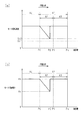
次に、ウインドガラスWGの作動中の負荷(例えば、ウインドガラスWGと車両ドアDRのベルトモール(図示略)との摺動負荷)が、使用環境等によって想定以上に大きくなる場合について、図2(a)(b)中の二点鎖線に従って説明する。この場合、通常定速区間A4及びスローストップ区間A1におけるモータ本体12の回転速度が前記負荷によって遅くなる。
Next, a case where the load during operation of the window glass WG (for example, the sliding load between the window glass WG and the belt molding (not shown) of the vehicle door DR) becomes larger than expected depending on the use environment or the like will be described with reference to FIG. (A) It demonstrates according to the dashed-two dotted line in (b). In this case, the rotation speed of the
P/WECU14は、減速区間A2において、モータ本体12の回転速度と第1閾値St1よりも大きい値である第2閾値St2とを比較する。そして、モータ本体12の回転速度が第2閾値St2以下となったとき、PWM制御部14aは、その時点(ウインドガラスWGが図2(a)(b)における位置P2に達した時点)でのモータ印加電圧の電圧値Vcを、それ以降のモータ印加電圧に設定する。これにより、ウインドガラスWGの位置P2から全閉位置Px側への閉作動では、モータ本体12が電圧値Vcに基づく回転速度で駆動される。そして、ウインドガラスWGが全閉位置Pxに到達してモータ本体12の回転速度が第1閾値St1以下となったとき、モータ本体12の駆動が停止される。
The P /
次に、本実施形態の特徴的な効果を記載する。
(1)P/WECU14(PWM制御部14a)は、ウインドガラスWGを全閉位置Px(可動範囲の端位置)に向かって作動させるとき、モータ印加電圧を一定値とする通常定速区間A4(第1区間)と全閉位置Pxとの間に設定された減速区間A2(第2区間)においてモータ印加電圧を前記一定値から漸減させる減速制御を実行する。また、P/WECU14は、モータ本体12の回転速度が第1閾値St1以下となったときにモータ本体12の駆動を停止させる停止制御を実行する。そして、PWM制御部14aは、減速区間A2におけるモータ本体12の回転速度が、第1閾値St1よりも大きい第2閾値St2以下となったとき、当該時点でのモータ印加電圧の電圧値Vcを、当該時点からウインドガラスWGが全閉位置Pxに到達して停止制御が実行されるまでの間のモータ印加電圧に設定する。
Next, characteristic effects of the present embodiment will be described.
(1) When the P / WECU 14 (PWM control unit 14a) operates the window glass WG toward the fully closed position Px (the end position of the movable range), a normal constant speed section A4 (a constant constant speed section A4) in which the motor applied voltage is constant. In the deceleration zone A2 (second zone) set between the first zone) and the fully closed position Px, deceleration control is executed to gradually decrease the motor applied voltage from the constant value. Further, the P /
この構成によれば、モータ印加電圧が通常定速区間A4での一定値から漸減される減速区間A2において、モータ本体12の回転速度がモータ駆動停止用の閾値である第1閾値St1よりも大きい第2閾値St2以下となったとき、その時点でのモータ印加電圧(電圧値Vc)が下限とされる。これにより、ウインドガラスWGの作動中の負荷が想定以上に大きい場合であっても、ウインドガラスWGが全閉位置Pxに到達する手前でモータ本体12の回転速度が第1閾値St1以下となってモータ本体12の駆動が停止されることを抑制できる。従って、ウインドガラスを閉めきることができなくなる不具合の発生を抑制できる。
According to this configuration, the rotation speed of the
なお、上記実施形態は、以下のように変更してもよい。
・上記実施形態では、ウインドガラスWGの閉作動(全閉位置Pxに向かう作動)における制御態様を例にとって説明したが、ウインドガラスWGの開作動(全開位置に向かう作動)に適用してもよい。
In addition, you may change the said embodiment as follows.
In the above embodiment, the control mode in the closing operation of the window glass WG (operation toward the fully closed position Px) has been described as an example. However, the control mode may be applied to the opening operation of the window glass WG (operation toward the fully open position). .
・上記実施形態のPWM制御部14aは、減速区間A2におけるモータ本体12の回転速度が第2閾値St2以下となったとき、その時点でのモータ印加電圧の電圧値Vcを、それ以降のモータ印加電圧に設定するが、これに特に限定されるものではない。例えば、図3(a)に示すように、減速区間A2におけるモータ本体12の回転速度が第2閾値St2以下となったとき、図3(b)に示すように、その時点(ウインドガラスWGが図3(a)(b)における位置P2に達した時点)以降のモータ印加電圧をバッテリ電圧Vbで一定としてもよい。これによれば、ウインドガラスWGの位置P2から全閉位置Px側への閉作動では、モータ本体12が通常定速区間A4と同等の回転速度で駆動される(図3(a)参照)。このため、上記実施形態と同様に、ウインドガラスWGの作動中の負荷が想定以上に大きい場合であっても、減速区間A2においてモータ本体12の回転速度がモータ本体12の回転速度が第1閾値St1以下となってモータ本体12の駆動が停止されることを抑制できる。
-When the rotational speed of the motor
・上記実施形態では、P/WECU14は、減速区間A2においてモータ本体12の回転速度と第2閾値St2とを比較するが、これに限らず、図4(a)に示すように、通常定速区間A4においてモータ本体12の回転速度と第2閾値St2とを比較してもよい。この場合においても、通常定速区間A4におけるモータ本体12の回転速度が第2閾値St2以下となったとき、PWM制御部14aは、その時点でのモータ印加電圧(本例ではバッテリ電圧Vb)を、それ以降のモータ印加電圧に設定する(図4(b)参照)。つまり、ウインドガラスWGの作動中の負荷が想定以上に大きく、通常定速区間A4におけるモータ本体12の回転速度が第2閾値St2以下となったときには、PWM制御部14aは、スローストップ区間A1においてもモータ印加電圧(モータ本体12の回転速度)を下降させないようにFET13bを制御する。このような制御によっても、ウインドガラスWGが全閉位置Pxに到達する手前でモータ本体12の回転速度が第1閾値St1以下となってモータ本体12の駆動が停止されることを抑制できる。
In the above embodiment, the P /
・スローストップ区間A1における減速の態様は上記実施形態に限定されるものではなく、適宜変更可能である。例えば、全閉位置Pxの手前の低速一定区間A3を設けずに、スロー開始位置P0から全閉位置Pxに到達するまでウインドガラスWGの作動速度を減速させてもよい(つまり、スロー開始位置P0から全閉位置Pxまでを減速区間A2としてもよい)。 -The aspect of deceleration in slow stop area A1 is not limited to the said embodiment, It can change suitably. For example, the operating speed of the window glass WG may be decelerated from the slow start position P0 to the fully closed position Px without providing the low speed constant section A3 before the fully closed position Px (that is, the slow start position P0). To the fully closed position Px may be set as the deceleration zone A2.)
・上記実施形態では、PWM制御部14aは、通常定速区間A4においてFET13bをオン固定(デューティ100%)とするが、これに限らず、通常定速区間A4においてFET13bをオンオフ駆動させて100%よりも低いデューティで一定としてもよい。
In the above embodiment, the PWM control unit 14a fixes the
・駆動回路13をリレー回路13aとFET13bとで構成したが、駆動回路の構成はこれに限らず、例えばFET等の半導体スイッチング素子を4個用いたフルブリッジ型駆動回路、半導体スイッチング素子を2個用いたハーフブリッジ型駆動回路を用いてもよい。
The
・開閉対象はウインドガラスWGでありそれを開閉するパワーウインドモータ11(パワーウインドシステム10)に適用したが、車両の他の開閉体駆動モータ(開閉体駆動システム)、例えばスライドルーフを駆動するモータ(システム)に適用してもよい。 The object to be opened / closed is the window glass WG and applied to the power window motor 11 (power window system 10) that opens / closes the window glass WG, but other opening / closing body drive motor (open / close body drive system) of the vehicle, for example, a motor for driving a slide roof (System) may be applied.
・上記した実施形態並びに各変形例は適宜組み合わせてもよい。 -You may combine embodiment mentioned above and each modification suitably.
11…パワーウインドモータ(開閉体駆動モータ)、12…モータ本体、14…パワーウインドECU(制御部)、DR…車両ドア、WG…ウインドガラス(開閉体)、A2…減速区間(第2区間)、A4…通常定速区間(第1区間)、Px…全閉位置(端位置)、St1…第1閾値、St2…第2閾値。
DESCRIPTION OF
Claims (3)
前記制御部は、前記開閉体を前記可動範囲の端位置に向かって作動させるとき、前記モータ印加電圧を一定値とする第1区間と前記端位置との間に設定された第2区間において前記モータ印加電圧を前記一定値から漸減させる減速制御と、前記モータ本体の回転速度が第1閾値以下となったときに前記モータ本体の駆動を停止させる停止制御とを実行する開閉体駆動モータであって、
前記制御部は、前記第1区間又は前記第2区間における前記モータ本体の回転速度が、前記第1閾値よりも大きい第2閾値以下となったとき、当該時点での前記モータ印加電圧以上の電圧値を、当該時点から前記開閉体が前記端位置に到達して前記停止制御が実行されるまでの間の前記モータ印加電圧に設定することを特徴とする開閉体駆動モータ。 A motor body for opening and closing a vehicle opening / closing body within a predetermined movable range, and operating the opening / closing body through the motor body by varying a motor applied voltage applied to the motor body based on position information of the opening / closing body A control unit for controlling the aspect,
In the second section set between the first section where the motor applied voltage is a constant value and the end position when the opening / closing body is operated toward the end position of the movable range, An open / close body drive motor that executes deceleration control for gradually decreasing the applied voltage of the motor from the constant value and stop control for stopping the driving of the motor body when the rotation speed of the motor body falls below a first threshold value. And
When the rotation speed of the motor body in the first section or the second section is equal to or less than a second threshold value that is greater than the first threshold value, the control unit is a voltage that is equal to or higher than the motor applied voltage at that time. A value is set to the motor applied voltage from the time point until the opening / closing body reaches the end position and the stop control is executed.
前記開閉体の前記端位置は、前記開閉体の全閉位置であることを特徴とする開閉体駆動モータ。 The opening / closing body drive motor according to claim 1,
The opening / closing body drive motor, wherein the end position of the opening / closing body is a fully closed position of the opening / closing body.
前記モータ本体の開閉対象である前記開閉体は、車両ドアに備えられるウインドガラスであることを特徴とする開閉体駆動モータ。 In the opening-and-closing body drive motor of Claim 1 or 2,
The opening / closing body drive motor, wherein the opening / closing body to be opened / closed of the motor body is a window glass provided in a vehicle door.
Priority Applications (6)
| Application Number | Priority Date | Filing Date | Title |
|---|---|---|---|
| JP2016079603A JP6610397B2 (en) | 2016-04-12 | 2016-04-12 | Opening and closing body drive motor |
| DE112017001988.5T DE112017001988T5 (en) | 2016-04-12 | 2017-04-11 | DRIVE MOTOR FOR AN OPENING AND CLOSING BODY |
| CN202010843990.0A CN111927241B (en) | 2016-04-12 | 2017-04-11 | Opening/closing body drive motor |
| US16/080,071 US10378264B2 (en) | 2016-04-12 | 2017-04-11 | Drive motor for opening and closing body |
| PCT/JP2017/014856 WO2017179585A1 (en) | 2016-04-12 | 2017-04-11 | Drive motor for opening and closing body |
| CN201780020403.4A CN109072660B (en) | 2016-04-12 | 2017-04-11 | Opening/closing body drive motor |
Applications Claiming Priority (1)
| Application Number | Priority Date | Filing Date | Title |
|---|---|---|---|
| JP2016079603A JP6610397B2 (en) | 2016-04-12 | 2016-04-12 | Opening and closing body drive motor |
Publications (2)
| Publication Number | Publication Date |
|---|---|
| JP2017190591A JP2017190591A (en) | 2017-10-19 |
| JP6610397B2 true JP6610397B2 (en) | 2019-11-27 |
Family
ID=60085759
Family Applications (1)
| Application Number | Title | Priority Date | Filing Date |
|---|---|---|---|
| JP2016079603A Active JP6610397B2 (en) | 2016-04-12 | 2016-04-12 | Opening and closing body drive motor |
Country Status (1)
| Country | Link |
|---|---|
| JP (1) | JP6610397B2 (en) |
Families Citing this family (2)
| Publication number | Priority date | Publication date | Assignee | Title |
|---|---|---|---|---|
| CN108798351B (en) * | 2018-05-29 | 2020-10-16 | 重庆海德世拉索系统(集团)有限公司 | Automobile window speed control circuit and method |
| JP2020117978A (en) * | 2019-01-25 | 2020-08-06 | 日本電産モビリティ株式会社 | Opening/closing body control device and structure |
-
2016
- 2016-04-12 JP JP2016079603A patent/JP6610397B2/en active Active
Also Published As
| Publication number | Publication date |
|---|---|
| JP2017190591A (en) | 2017-10-19 |
Similar Documents
| Publication | Publication Date | Title |
|---|---|---|
| CN109072660B (en) | Opening/closing body drive motor | |
| JP6955204B2 (en) | Opening and closing body drive device | |
| US10041286B2 (en) | Method of controlling a movable closure member of a vehicle | |
| JP6897599B2 (en) | Power window controller | |
| JP6610397B2 (en) | Opening and closing body drive motor | |
| JP2018162623A (en) | Opening/closing body driving device | |
| JP6988838B2 (en) | Open / close body control device | |
| JP6394900B2 (en) | Vehicle window opening and closing device | |
| JP6610396B2 (en) | Power window motor | |
| JP7028195B2 (en) | Open / close member control device | |
| CN111691780B (en) | Vehicle opening/closing body control device | |
| JP6880815B2 (en) | Switch drive motor and switch drive system | |
| JP7031621B2 (en) | Open / close body control device | |
| JP2020117978A (en) | Opening/closing body control device and structure | |
| US11309813B2 (en) | Opening/closing body drive device and control method thereof | |
| WO2020153469A1 (en) | Opening/closing member control device | |
| JP6988742B2 (en) | Opening / closing member control device and motor with control device | |
| US11201580B2 (en) | Opening/closing body drive device and control method thereof | |
| JP6596832B2 (en) | Vehicle window opening and closing device | |
| JP6485081B2 (en) | Vehicle window opening and closing device | |
| JP6432367B2 (en) | Vehicle window opening and closing device | |
| JP2022112134A (en) | Opening/closing member control device | |
| JP2005030200A (en) | Opening/closing member controller | |
| JP2020102910A (en) | Opening/closing body control device and motor | |
| JP2016142042A (en) | Vehicle window opening and closing device |
Legal Events
| Date | Code | Title | Description |
|---|---|---|---|
| A711 | Notification of change in applicant |
Free format text: JAPANESE INTERMEDIATE CODE: A712 Effective date: 20180501 |
|
| A621 | Written request for application examination |
Free format text: JAPANESE INTERMEDIATE CODE: A621 Effective date: 20190121 |
|
| TRDD | Decision of grant or rejection written | ||
| A01 | Written decision to grant a patent or to grant a registration (utility model) |
Free format text: JAPANESE INTERMEDIATE CODE: A01 Effective date: 20191001 |
|
| A61 | First payment of annual fees (during grant procedure) |
Free format text: JAPANESE INTERMEDIATE CODE: A61 Effective date: 20191014 |
|
| R151 | Written notification of patent or utility model registration |
Ref document number: 6610397 Country of ref document: JP Free format text: JAPANESE INTERMEDIATE CODE: R151 |
|
| R250 | Receipt of annual fees |
Free format text: JAPANESE INTERMEDIATE CODE: R250 |
|
| R250 | Receipt of annual fees |
Free format text: JAPANESE INTERMEDIATE CODE: R250 |