JP6610185B2 - Image processing device - Google Patents
Image processing device Download PDFInfo
- Publication number
- JP6610185B2 JP6610185B2 JP2015222049A JP2015222049A JP6610185B2 JP 6610185 B2 JP6610185 B2 JP 6610185B2 JP 2015222049 A JP2015222049 A JP 2015222049A JP 2015222049 A JP2015222049 A JP 2015222049A JP 6610185 B2 JP6610185 B2 JP 6610185B2
- Authority
- JP
- Japan
- Prior art keywords
- viewpoint position
- user
- video
- image
- terminal
- Prior art date
- Legal status (The legal status is an assumption and is not a legal conclusion. Google has not performed a legal analysis and makes no representation as to the accuracy of the status listed.)
- Active
Links
Images


Description
本発明は、オブジェクトの三次元データに基づいて当該オブジェクトの三次元映像をユーザに提示するよう構成された画像処理装置に関する。 The present invention relates to an image processing apparatus configured to present a 3D video of an object to a user based on the 3D data of the object.
従来より、3次元CADシステムの3次元画像データから2次元データを生成し、生成した2次元データに基づいて印刷を行う装置が提案されている。 Conventionally, there has been proposed an apparatus that generates two-dimensional data from three-dimensional image data of a three-dimensional CAD system and performs printing based on the generated two-dimensional data.
つまり、特許文献1には、記憶装置に3次元画像データを記憶しておき、ユーザがタッチパネルなどを操作することによって指示した出力形式に基づいて、3次元画像データを加工して2次元データを生成しこれを印刷する印刷装置が開示されている。
That is, in
また、特許文献2には、入力した3次元データに所定の情報に応じて3次元幾何変換を行い、変換後の3次元データを2次元平面に投影し補間した後のデータを可視出力する印刷装置が開示されている。
Further,
これらの印刷装置は、3次元CADシステムの3次元画像データなどに基づいて、2次元画像を表示するための表示装置に2次元画像を表示するものである。そのため、3次元画像データを加工などして2次元データを生成する際に、その視点位置の指示の方法が限定されることとなる。つまり、表示装置には2次元画像のみが表示されるものであるから、その2次元画像を表示するために、マウスやキ−ボ−ドなどを操作することによって視点位置を変更する必要がある。視点位置を指示するに当たって、このような操作は直感的ではなく、操作が煩雑である。 These printing apparatuses display a two-dimensional image on a display device for displaying a two-dimensional image based on the three-dimensional image data of the three-dimensional CAD system. Therefore, when the two-dimensional data is generated by processing the three-dimensional image data, the method for specifying the viewpoint position is limited. That is, since only a two-dimensional image is displayed on the display device, it is necessary to change the viewpoint position by operating a mouse, a keyboard, or the like in order to display the two-dimensional image. . In specifying the viewpoint position, such an operation is not intuitive and the operation is complicated.
一方、三次元のオブジェクトを三次元映像(立体映像)としてユーザに提示する装置として、ホログラムを用いて空間に三次元映像を投影する装置、レンチキラーレンズや眼鏡を用いて左右の目に視差を生じさせて三次元映像を提示する装置などがある(特許文献3、非特許文献1〜3)。
On the other hand, as a device that presents a three-dimensional object to a user as a three-dimensional image (stereoscopic image), a device that projects a three-dimensional image into a space using a hologram, parallax between the left and right eyes using a lenticular lens and glasses There are devices that generate a 3D video image (Patent Document 3, Non-Patent
さて、特許文献1、2などの印刷装置は、上に述べたように、マウスなどを操作することによって視点位置を変更するので、視点位置の指示における操作が直感的ではなく、操作が煩雑である。しかも、変更された視点位置の2次元画像を表示するために、印刷装置は、視点位置の変更のたび毎に3次元画像データから2次元画像を生成するという煩雑な処理を行う必要がある。
Now, as described above, since the printing apparatus of
また、非特許文献1で開示される従来の装置では、三次元映像を提示することによりユーザが三次元映像そのものを体験して楽しむことに主眼が置かれている。
Further, in the conventional apparatus disclosed in Non-Patent
本発明は、オブジェクトの三次元映像をユーザに提示するとともに、提示された三次元映像に対してユーザの視点位置を容易に特定することが可能であり、特定された視点位置からの二次元映像を煩雑な処理を必要とすることなくユーザに提供できることを目的とする。 The present invention presents a 3D video of an object to a user and can easily specify the user's viewpoint position with respect to the presented 3D video, and the 2D video from the specified viewpoint position. Is provided to the user without requiring complicated processing.
本発明の実施形態に係る画像処理装置は、オブジェクトの三次元データに基づいて、ユーザの視点位置の移動によって当該オブジェクトの見え方が変化する三次元映像を、ユーザに提示する三次元映像提示手段と、提示された前記三次元映像に対するユーザの視点位置を特定する視点位置特定手段と、前記視点位置特定手段により特定された視点位置から見たときの前記オブジェクトの二次元映像を前記三次元データに基づいて生成する二次元映像生成手段と、前記二次元映像を所定の形式で出力する出力手段と、ユーザが保持する携帯端末から無線通信によって送信される端末指令を受信する端末指令受信手段とを有し、前記端末指令受信手段は、当該携帯端末において検出された端末位置情報および当該携帯端末において撮影された前記三次元映像の写真画像を含む前記端末指令を受信したときに、前記端末位置情報および前記写真画像を前記視点位置特定手段に送り、前記視点位置特定手段は、前記端末位置情報および前記写真画像に基づいて前記視点位置を特定する。 An image processing apparatus according to an embodiment of the present invention provides 3D video presentation means for presenting to a user a 3D video in which the appearance of the object changes according to movement of the user's viewpoint position based on the 3D data of the object Viewpoint position specifying means for specifying the viewpoint position of the user with respect to the presented 3D video, and the 2D video of the object when viewed from the viewpoint position specified by the viewpoint position specifying means. Two-dimensional video generation means for generating based on the output, output means for outputting the two-dimensional video in a predetermined format, terminal command receiving means for receiving a terminal command transmitted by wireless communication from a portable terminal held by the user, The terminal command receiving means includes the terminal position information detected in the mobile terminal and the image taken in the mobile terminal. When the terminal command including a photographic image of a three-dimensional video is received, the terminal position information and the photographic image are sent to the viewpoint position specifying means, and the viewpoint position specifying means is based on the terminal position information and the photographic image. To identify the viewpoint position.
好ましくは、前記視点位置特定手段は、前記三次元映像提示手段の近辺に配置され、前記三次元映像提示手段により提示された前記三次元映像を見ているユーザを撮影するカメラと、前記カメラによって撮影された画像におけるユーザの眼球の位置に基づいて前記視点位置を特定するユーザ画像処理手段と、を有する。 Preferably, the viewpoint position specifying unit is disposed in the vicinity of the 3D video presentation unit, and a camera that captures a user who is viewing the 3D video presented by the 3D video presentation unit, and the camera User image processing means for specifying the viewpoint position based on the position of the user's eyeball in the photographed image.
本発明によると、オブジェクトの三次元映像をユーザに提示するとともに、提示された三次元映像に対してユーザの視点位置を容易に特定することが可能であり、特定された視点位置からの二次元映像を煩雑な処理を必要とすることなくユーザに提供できることができる。 According to the present invention, it is possible to present a 3D video of an object to a user, and to easily identify the user's viewpoint position with respect to the presented 3D video, The video can be provided to the user without requiring complicated processing.
〔第1の実施形態〕
図1には第1の実施形態の画像処理装置1の構成が示されている。また、図2には視点位置特定部13の構成の例が、図3にはオブジェクトの三次元データ110の例が、図4にはオブジェクトが配置された全体座標系とユーザUの視座標系との関係の例が、図5には提示された三次元映像120に対するユーザUの視点位置S1の例が、図6には各視点位置でのオブジェクトの二次元映像152の例が、それぞれ示されている。
[First Embodiment]
FIG. 1 shows a configuration of an
図1ないし図6において、画像処理装置1は、記憶部11、三次元映像提示部12、視点位置特定部13、二次元映像生成部14、出力部15、および出力指示部16などを有する。
1 to 6, the
記憶部11は、三次元データ110、その他のデータおよびプログラムなどを記憶する。三次元データ110は、種々のオブジェクト(対象物)について、オブジェクトの外観形状、材質や色などの表面状態、または構造などを表現することの可能な三次元データである。三次元データ110は、ソリッドモデル、ボリュ−ムモデル、サーフェスモデル、またはワイヤーフレームモデルなどのデータを用いることが可能である。
The
三次元データ110は、現存するオブジェクトを複数のカメラや三次元カメラなどにより撮影して、またCG(コンピュータグラフィックス)の技術を用いて、またこれらを組み合わせて生成することが可能であり、このような従来の技術を用いて生成された三次元データを本実施形態の三次元データ110として用いることが可能である。
The three-
三次元映像提示部12は、運動視差を得ることのできる三次元映像表示装置であり、オブジェクトの三次元データ110に基づいて、当該オブジェクトの三次元映像120をユーザUに提示(表示)する(図5を参照)。
The 3D
三次元映像提示部12として、種々の方式、原理、構成、および仕様のものが用いられる。例えば、従来の技術の項でも示したように、インテグラル方式(インテグラルフォトグラフィ方式)の三次元画像表示装置、これ以外の方式でレンチキラーレンズや眼鏡を用いて左右の目に視差を生じさせて三次元映像を提示するもの、ホログラムを用いて空間に三次元映像を投影する方式のもの、ボクセルを用いる体積型のものなど、公知の3Dテレビ、立体画像表示装置、または三次元映像表示装置などを使用可能である。
Various types, principles, configurations, and specifications are used as the 3D
なお、インテグラル方式では、三次元データ110の作成に際し、例えば、対象物が反射するそれぞれの方向への反射光をレンズアレイを用いることで分離し、それぞれ記録する。これを三次元映像提示部12で再生する際に、撮影に用いたレンズアレイを用いることで、それぞれの光線を合成し、元の反射光(各方向への光線が合成された状態) を再現する。つまり、全方向に対する反射光をレンズアレイを使って分離して一方向毎に記録し、再生時にそれを合成する。対象物の反射光(それぞれの方向への光線)を再現するため、見る方向によって得られる映像が異なる。つまり、インテグラル方式では、両眼における視差に加えて、ユーザ(視聴者)の視点位置の移動に応じて映像の見え方が変化する「運動視差」が生じる。
In the integral method, when the three-
インテグラル方式の場合には、仕様が同じレンズアレイを用いて撮影と再生とで同一の環境を作るので、対象物−レンスアレイ−カメラの相互の位置関係と、ユーザの眼球−レンズアレイ−ディスプレイの相互の位置関係とは合致する。つまり、レンズアレイを通して撮影した映像を、三次元データ110に基づいてシミュレートするので、その映像を二次元のディスプレイに表示することで位置関係は保たれる。
In the case of the integral system, the same environment is created for shooting and playback using a lens array with the same specifications, so that the positional relationship between the object-lens array-camera and the user's eyeball-lens array-display The mutual positional relationship agrees. That is, since the image captured through the lens array is simulated based on the three-
視点位置特定部13は、提示された三次元映像120に対するユーザの視点位置S1を特定する。
The viewpoint
視点位置特定部13は、三次元映像提示部12の近辺に配置され、三次元映像提示部12により提示された三次元映像120を見ているユーザUを撮影するカメラ132a〜dと、カメラ132a〜dによって撮影された画像におけるユーザUの眼球の位置に基づいて視点位置S1を特定するユーザ画像処理部130と、を有する(図2を参照)。
The viewpoint
本実施形態では、複数のカメラ132a〜dが設けられ、ユーザ画像処理部130は、複数のカメラ132a〜dによって撮影された複数の画像に基づいて、視点位置S1を特定する。また、ユーザ画像処理部130は、ユーザUについて設定された左右いずれかの眼球の位置に基づいて視点位置S1を特定する。
In the present embodiment, a plurality of
また、視点位置特定部13は、カメラ132a〜dによって撮影された画像に複数のユーザUが写っているときに、そのうちの1人を視点位置S1を決めるためのユーザUとして特定するユーザ特定部131を有する。つまり、ユーザ特定部131は、出力部15に対する出力指示S2が与えられたときに、当該出力指示S2に関連した動作を行ったユーザUを、視点位置S1を特定するためのユーザUとして特定することができる。例えば、ユーザUは、操作キーやタッチパネルなどを操作し、音声を発し、またはジェスチャーを示すなどによって、出力指示S2を与えることができる。
The viewpoint
また、ユーザUによるタッチパネルへのタッチ操作、またはマウスまたはキーボードなどへの操作に基づいて、視点位置特定部13が視点位置S1を特定することも可能である。
The viewpoint
二次元映像生成部14は、視点位置特定部13により特定された視点位置S1から見たときのオブジェクトの二次元映像140を、三次元データ110に基づいて生成する。なお、この二次元映像140は、正確には二次元映像のデータである。
The 2D
出力部15は、入力された二次元映像140を所定の形式で出力する。例えば、出力部15が表示装置を備える場合に、その画面151に二次元映像152を表示する。また、出力部15が印刷装置を備える場合に、シート状の用紙PPに二次元映像153を印刷して表示する。また、ファクシミリ装置を備える場合に、二次元映像140をファクシミリ送信する。
The
出力部15は、視点位置S1と三次元映像120との距離がより大きい場合に、二次元映像140の拡大率をより大きくして出力する。つまり、視点位置S1が三次元映像120から遠くなるにしたがって二次元映像140が小さくなるので、これを補うために、二次元映像140を大きくし、画面151または用紙PPの全面に二次元映像152,153を表示する。
When the distance between the viewpoint position S1 and the
出力部15には、出力指示部16から出力指示S2が入力されている。出力部15による用紙PPへの印刷は、出力指示S2が入力されたときに実行される。また、出力部15による印刷以外の出力についても、出力指示S2が入力されたときに実行されるようにしてもよい。
An output instruction S <b> 2 is input to the
出力指示部16は、出力部15に対し、主として二次元映像153を印刷させるための出力指示S2を出力する。出力指示部16は、ハ−ドウエアまたはソフトウエアによる操作キー、またはキ−ボードやマウスなどを含めて構成することができる。
The
また、視点位置特定部13を、ユーザUの操作によって視点位置S1を特定できるように構成した場合に、ユーザUがその操作によって視点位置S1を特定したときに同時に出力指示S2を出力するようにしてもよい。また、複数のユーザUが居てそのうちの一人が出力指示S2に関連した動作を行った場合に、これによってユーザUおよび視点位置S1を特定するとともに、同時に出力指示S2を出力して二次元映像153の印刷を行うようにしてもよい。
In addition, when the viewpoint
以下、さらに詳しく説明する。 This will be described in more detail below.
図3に示すように、オブジェクトの三次元データ110は、全体座標系(x,y,z)の空間に配置されている。つまり、三次元データ110を構成する各点の位置は座標(x,y,z)により特定される。なお、全体座標系において、三次元データ110の姿勢を変更することが可能である。
As shown in FIG. 3, the three-
三次元映像提示部12は、三次元データ110に基づいて同じ全体座標系に三次元映像120を提示することが可能である。その際に、全体座標系における三次元映像120の位置を変更し、回転し、または拡大縮小を行うことが可能である。
The 3D
図4に示すように、ユーザUの視点位置S1を原点とした座標系が視座標系(xu,yu,zu)である。視座標系(xu,yu,zu)と全体座標系(x,y,z)とは、設定された種々の空間関係となるように配置され、図4においては、視座標系のzu軸と全体座標系のz軸とが一致した状態が示されている。 As shown in FIG. 4, the coordinate system with the viewpoint position S1 of the user U as the origin is the visual coordinate system (xu, yu, zu). The visual coordinate system (xu, yu, zu) and the global coordinate system (x, y, z) are arranged so as to have various set spatial relationships. In FIG. The state where the z-axis of the global coordinate system coincides is shown.
三次元映像120を、視点位置S1から、zu軸と垂直な平面141に投影することによって、視点位置S1から見た二次元映像140が得られる。なお、二次元映像140を投影するための平面141を、視点位置S1と三次元映像120との間に配置してもよい。
By projecting the
そして、全体座標系(x,y,z)と視座標系(xu,yu,zu)との配置関係を変更することによって、例えば原点間の距離、および、x軸とxu軸、y軸とyu軸、z軸とzu軸のそれぞれのなす角度を変更することによって、全体座標系(x,y,z)に配置される三次元データ110または三次元映像120に対する視点位置S1を任意に変更することができる。したがって、全体座標系における視点位置S1の位置を変更することによって、視座標系における三次元映像120の配置を任意に変更することができる。つまり、これによって任意の視点位置S1から見たときの二次元映像140を得ることができる。
Then, by changing the positional relationship between the global coordinate system (x, y, z) and the visual coordinate system (xu, yu, zu), for example, the distance between the origins, the x axis, the xu axis, and the y axis The viewpoint position S1 with respect to the three-
図5において、三次元映像提示部12に三次元映像120が提示されており、三次元映像提示部12の前方に居るユーザUが、Ua、Ub、Uc、Udのように移動する様子が示されている。
In FIG. 5, the
ユーザUの移動にしたがって、その視点位置S1は、S1a、S1b、S1c、S1dと移動する。ユーザUの眼球の位置は、カメラ132a〜dによって撮影された画像を処理することによって決定され、そのときの視点位置S1が特定される。この場合に、それぞれのカメラ132a〜dでユーザUの眼球を撮影し、各カメラ132a〜dから見た眼球の方向を合成することによって視点位置S1を特定することができる。また、撮影した眼球の瞳孔の向きから視線の向きを特定することも可能である。
As the user U moves, the viewpoint position S1 moves to S1a, S1b, S1c, and S1d. The position of the eyeball of the user U is determined by processing images taken by the
通常、ユーザUの眼球の位置は2ヵ所となるので、例えばその中間の位置を視点位置S1として特定することができる。また、ユーザUが自分の利き目を予め画像処理装置1に登録して設定しておくことが可能である。その場合に、利き目として設定された左右いずれかの眼球の位置に基づいて視点位置S1を特定することになる。
Usually, since the position of the eyeball of the user U is two, an intermediate position can be specified as the viewpoint position S1, for example. Also, the user U can register and set his / her dominant eye in the
図6(A)〜(D)には、三次元映像120を各視点位置S1a〜dから見たときの二次元映像152a〜dが示されている。二次元映像152a〜dは画面151に表示されたものであるが、印刷された場合には同様な二次元映像153a〜dが用紙PPに表示される。
6A to 6D show two-
また、図5において、異なる複数のユーザUa〜dが同時に三次元映像提示部12の前方に居るとした場合に、ユーザ特定部131は、そのうちの1人を視点位置S1を特定するためのユーザUを選択する。この場合に、例えば、ユーザ特定部131は、出力部15に対する出力指示S2、例えば印刷指示を与えたユーザUを、視点位置S1を特定するためのユーザUとして選択する。そのような指示のための動作を行ったユーザUは、カメラ132a〜dで撮影した画像について画像認識などの画像処理によって決定することが可能である。
In FIG. 5, when a plurality of different users Ua to d are simultaneously in front of the 3D
このように、視点位置特定部13は、カメラ132a〜dによって撮影される画像に基づいて、またはユーザUによる操作などに基づいて、視点位置S1を特定する。二次元映像生成部14は、特定された視点位置S1から見た二次元映像140を生成し、出力部15は二次元映像140を画面151に表示しまたは用紙PPに印刷する。
As described above, the viewpoint
このように、オブジェクトの三次元映像120をユーザUに提示するとともに、提示された三次元映像120に対してユーザUの視点位置S1を容易に特定することが可能であり、特定された視点位置S1からの二次元映像140を煩雑な処理を必要とすることなくユーザに提供することができる。
In this manner, the
特に、三次元映像提示部12として、ユーザUの視点位置S1の移動に応じて運動視差が生じる形式の装置が用いられるので、三次元映像提示部12に対するユーザUの位置に応じて三次元映像120の見え方が変化し、かつその時々の視点位置S1を視点位置特定部13が特定するので、ユーザUは好きな姿勢で三次元映像120を見ながら、その視点位置S1からの二次元映像152を画面151で確認することができる。そして、必要なタイミングで出力指示S2を与えることにより、煩雑な処理を行うことなく、ユーザUが見たままの二次元映像153を印刷して出力することができる。
In particular, as the 3D
つまり、本実施形態における画像処理装置1では、簡易で直感的な操作によって、オブジェクトについて任意の視点位置S1からの二次元映像152,153を得ることができる。また、1つの三次元映像120を複数のユーザUが見ている場合でも、カメラ132a〜dによる撮影とその画像処理またはユーザUの動作などによって、二次元映像152,153を欲しているユーザUおよび視点位置S1を特定し、所望の印刷物などを得ることができる。
That is, in the
このように、本実施形態における画像処理装置1によると、三次元映像120の閲覧から印刷を即座に行うことができ、印刷のために視点位置S1を設定する面倒な操作が不要である。そのため、三次元映像提示部12において、印刷設定のための表示領域を設ける必要がなく、三次元映像提示部12の全体を三次元映像120の提示と閲覧に用いることができる。
〔第2の実施形態〕
次に、第2の実施形態の画像処理装置1Bについて説明する。
Thus, according to the
[Second Embodiment]
Next, an image processing apparatus 1B according to the second embodiment will be described.
第2の実施形態の画像処理装置1Bでは、ユーザUが保持する携帯端末21との無線通信による連携が図られており、携帯端末21から送信される端末指令に基づいて、視点位置S1およびユーザUの特定などが行われる。画像処理装置1Bにおける基本的な機能および動作は第1の実施形態の画像処理装置1と同様であるので、同様な部分には同じ符号を付してここでの説明を省略しまたは簡略化する。
In the image processing apparatus 1B of the second embodiment, the wireless communication with the
図7には第2の実施形態の画像処理装置1Bの構成が示されている。 FIG. 7 shows the configuration of the image processing apparatus 1B of the second embodiment.
図7において、画像処理装置1Bは、記憶部11、三次元映像提示部12、視点位置特定部13、二次元映像生成部14、出力部15、出力指示部16、および端末指令受信部17などを有する。
In FIG. 7, the image processing apparatus 1B includes a
携帯端末21は、状態取得部211、撮影部212、操作制御部213、および通信部214などを有する。携帯端末21は、ユーザUによって保持されるものであるが、所定の位置に置いておくことも可能である。携帯端末21として、携帯電話機、スマ−トホン、タブレット端末、その他の端末装置などが用いられる。
The
状態取得部211は、当該携帯端末21の位置および姿勢などの情報を、GPSおよび姿勢センサーなどに基づく端末位置情報S3aとして取得する。
The
撮影部212は、携帯端末21に搭載されたカメラに基づく静止画または動画を、写真画像S3bとして取得する。例えば、ユーザUは、撮影部212によって、画像処理装置1Bの三次元映像提示部12により提示された三次元映像120を撮影することができる。その場合に、三次元映像120の周辺の画像、例えば三次元映像提示部12に表示された三次元映像120以外の画像、画像処理装置1Bの外観、または画像処理装置1Bの周辺などを、背景として同時に撮影することができる。
The
操作制御部213は、携帯端末21における種々の操作および制御を行うとともに、画像処理装置1Bに対する操作および制御を行うこともできる。また、操作制御部213は、画像処理装置1Bにおける印刷の際の拡大率(縮小率)などを示す拡大縮小情報S3cを生成する。操作制御部213には、画像処理装置1Bと連携して画像処理装置1Bを制御しまたは操作するためのアプリケーション(コンピュータプログラム)が搭載されている。
The operation control unit 213 can perform various operations and controls on the
通信部213は、画像処理装置1Bの端末指令受信部17との無線通信、およびネットワ−クとの無線通信などを行う。無線通信には、例えばBluetooth(登録商標)、IEEE802などによる無線LANなどが用いられる。
The communication unit 213 performs wireless communication with the terminal
無線通信によって、携帯端末21から画像処理装置1Bに対して、端末指令S3を送信する。端末指令S3として、端末位置情報S3a、写真画像S3b、または拡大縮小情報S3cなどが含まれる。
A terminal command S3 is transmitted from the
他方、画像処理装置1Bにおいて、端末指令受信部17は、ユーザUが保持する携帯端末21から無線通信によって送信される端末指令S3を受信する。端末指令受信部17は、携帯端末21において検出された端末位置情報S3aを含む端末指令S3を受信したときに、端末位置情報S3aを視点位置特定部13に送る。視点位置特定部13は、端末位置情報S3aに基づいて視点位置S1を特定する。
On the other hand, in the image processing apparatus 1B, the terminal
また、端末指令受信部17は、端末位置情報S3aに加えて、携帯端末21において撮影された三次元映像120の写真画像S3bを含む端末指令S3を受信したときに、端末位置情報S3aおよび写真画像S3bを視点位置特定部13に送る。視点位置特定部13は、端末位置情報S3aおよび写真画像S3bに基づいて視点位置S1を特定する。
In addition to the terminal position information S3a, the terminal
また、端末指令受信部17は、携帯端末21において撮影された三次元映像120およびその背景の写真画像S3bを含む端末指令S3を受信したときに、写真画像S3bを二次元映像生成部14に送る。二次元映像生成部14は、三次元データ110に基づいて生成したオブジェクトの二次元映像140と、写真画像S3bに含まれる背景とを合成して得られる二次元映像140Gを生成する。
The terminal
また、端末指令受信部17は、拡大縮小情報S3cを含む端末指令S3を受信したときに、拡大縮小情報S3cを出力部15に送る。出力部15は、拡大縮小情報S3cに基づいて拡大または縮小された二次元映像152,153を出力する。
Further, the terminal
例えば、ユーザUが、撮影部212によって、画像処理装置1Bの三次元映像提示部12により提示された三次元映像120を撮影すると、撮影された写真画像S3bを保持するとともに、このときの携帯端末21の位置および姿勢を示す端末位置情報S3aを取得する。そして、端末位置情報S3aおよび写真画像S3bを、通信部213から画像処理装置1Bに送信する。
For example, when the user U captures the
画像処理装置1Bにおいて、端末指令受信部17がそれらを受信する。端末指令受信部17は、視点位置特定部13に端末位置情報S3aを送り、視点位置特定部13において、端末位置情報S3aに基づいて視点位置S1を特定する。また、二次元映像生成部14では、端末指令受信部17から送られてきた写真画像S3bのうち、背景の部分はそのまま生かし、オブジェクトの三次元映像120が写った部分の写真画像(二次元画像)を、携帯端末21からの端末位置情報S3aに基づく視点位置S1により三次元データ110から生成した二次元映像140と置き換える。このようにして生成した二次元映像140Gを出力部15に送る。出力部15は、二次元映像140Gを印刷する。
In the image processing apparatus 1B, the terminal
三次元映像提示部12により提示される三次元映像120は、通常、低解像度で画質が粗いため、それを撮影した写真画像S3bでは三次元映像120の部分の画質は悪い。他方、三次元データ110から生成した二次元映像140は、通常、高解像度であり、高画質である。写真画像S3bの三次元映像120の部分を三次元データ110から生成した二次元映像140と置き換えることにより、写真画像S3bのうちの画質の悪い部分が高画質の画像となり、背景をも含めて高画質の印刷物が得られる。
〔複合機としての実施形態〕
次に、上に述べた画像処理装置1,1Bを、コピー機、プリンタ、およびファクシミリ機などの機能を集約した複合機として実施した形態について説明する。つまり、本実施形態の複合機1Cは、上に述べた画像処理装置1,1Bの機能を備えたMFP(Multi-functional Peripheral :多機能機)であるが、画像処理装置1,1Bの機能については既に説明したのでここでの説明は省略する。
Since the
[Embodiment as MFP]
Next, a description will be given of an embodiment in which the above-described
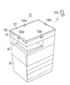
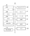
図8には複合機1Cを斜め上方からみた外観形状の例が、図9には複合機1Cのハードウェア構成が、それぞれ示されている。
FIG. 8 shows an example of the external shape of the
図8および図9において、複合機1Bは、三次元ディスプレイ12C、スキャナ31、プリンタ部32、給紙部33、補助記憶装置34、カメラ133、および制御部30などを備える。
8 and 9, the multi-function device 1B includes a three-
三次元ディスプレイ12Cは、複合機1Cの上部において表示面121が水平方向となるように配置されており、表示面121に運動視差を有する三次元映像120を提示することが可能である。また、三次元ディスプレイ12Cは、ユーザUによる入力操作のための画面、ユーザが各種のドキュメントを閲覧するための画面などの様々な画面を、制御部30からの指令にしたがって表示することが可能である。
The three-
三次元ディスプレイ12Cは、スキャナ31のプラテンガラスを覆うカバーとして、本体の一側面に沿う軸を中心として開閉可能である。スキャナ31を使用する場合には、ユーザUは三次元ディスプレイ12Cをその左側を持ち上げて開く。
The three-
スキャナ31は、プラテンガラスの上に置かれた原稿シートの画像を光学的に読み取って入力する。スキャナ31の外周面には、複合機1Cの周辺に居るユーザUを撮影するための複数のカメラ133a〜dが配置されている。これらカメラ133a〜dによって得られる撮影画像は、視点位置の特定、複数の中から1人のユーザUの選択、ユーザUの位置の検知、およびユーザUの判別などに用いられる。
The
プリンタ部32は、電子写真法によって用紙に画像を印刷する。給紙部33は、用紙を収納しておくための複数の給紙カセットを備え、用紙を1枚ずつ繰り出してプリンタ部32に供給する。
The
通信部34は、ユーザの保持する携帯端末21などと無線通信を行う。
The
補助記憶装置35は、三次元データの他、制御部30から送られてくる画像データ、その他のデータを記憶する。補助記憶装置35として、ハードディスクドライブまたはSSD(Solid State Drive )などが用いられる。
The
制御部30は、複合機1Cの全体的な制御を行う。制御部30は、CPU(Central Processing Unit )301、RAM(Random Access Memory)302、ROM(Read Only Memory)303、および画像処理部304などを備える。ROM303には、複合機1Cを、画像処理装置、プリンタ、コピー機、ファクシミリ機などとして動作させるためのコンピュータプログラムが記憶されている。
The
なお、図8には、複合機1Cと無線通信が可能な携帯端末21Cが示されている。携帯端末21Cは、上に述べた携帯端末21と同様な機能を有する。
FIG. 8 shows a portable terminal 21C capable of wireless communication with the
複合機1において、三次元ディスプレイ12Cは、三次元データに基づいて三次元映像を提示し、三次元映像に対しユーザUによって特定された視点位置からの二次元映像を表示しまたは印刷することが可能である。
In the
次に、複合機1Cにおける二次元映像の出力に関する処理の概略の流れを、図10〜図12に示すフローチャートに基づいて説明する。 Next, a general flow of processing related to the output of 2D video in the multifunction peripheral 1C will be described based on the flowcharts shown in FIGS.
図10において、三次元ディスプレイ12Cに三次元映像を提示する(#11)。三次元映像は、ユーザUの視点位置の移動によって見え方が変化する。視点位置を特定すると(#12)、特定された視点位置から見たときの二次元映像が三次元データに基づいて生成される(#13)。ユーザUが印刷を指示すると、二次元映像が用紙に印刷される(#14)。
In FIG. 10, a 3D image is presented on the
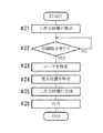
図11において、三次元ディスプレイ12Cに三次元映像を提示する(#21)。複数のユーザUが居る中で印刷の指示があった場合に(#22でイエス)、1人のユーザUを特定し(#23)、視点位置を特定する(#24)。特定された視点位置から見たときの二次元映像が三次元データに基づいて生成され(#25)、それが用紙に印刷される(#26)。
In FIG. 11, a 3D image is presented on the
図12において、三次元ディスプレイ12Cに三次元映像を提示する(#31)。ユーザUが携帯端末21Cでそれを撮影すると(#32)、その写真画像および端末位置情報が複合機1Cに送信される。複合機1Cは、写真画像および端末位置情報を受信すると(#33)、それらに基づいて視点位置を特定し(#34)、オブジェクトの二次元映像を生成する(#35)。生成した二次元映像と携帯端末21Cから送られてきた写真画像の背景の部分とを合成し、合成した二次元映像を得る(#36)。合成した二次元映像を用紙に印刷する(#37)。
In FIG. 12, a 3D image is presented on the
上述の実施形態の複合機1Cによると、オブジェクトの三次元映像をユーザUに提示するとともに、提示された三次元映像に対してユーザUの視点位置を容易に特定することが可能であり、特定された視点位置からの二次元映像を煩雑な処理を必要とすることなくユーザに提供することができる。
According to the
また、生成した二次元映像と携帯端末21Cで撮影した写真画像の背景の部分とを合成することによって、背景が写り込んだ二次元映像が得られるとともに、背景をも含めて高画質の印刷物が得られる。 Further, by synthesizing the generated 2D image and the background portion of the photographic image taken by the mobile terminal 21C, a 2D image including the background can be obtained, and a high-quality printed matter including the background can be obtained. can get.
上述の実施形態において、記憶部11、三次元映像提示部12、視点位置特定部13、二次元映像生成部14、出力部15、出力指示部16、端末指令受信部17、画像処理装置1,1B、および複合機1Cの全体または各部の構成、処理の内容、順序、またはタイミングなどは、本発明の趣旨に沿って適宜変更することができる。
In the above-described embodiment, the
1,1B 画像処理装置
1C 複合機(画像処理装置)
11 記憶部
12 三次元映像提示部(三次元映像提示手段)
12C 三次元ディスプレイ(三次元映像提示手段)
13 視点位置特定部(視点位置特定手段)
14 二次元映像生成部(二次元映像生成手段)
15 出力部(出力手段)
16 出力指示部
17 端末指令受信部(端末指令受信手段)
21,21C 携帯端末
30 制御部
110 三次元データ
120 三次元映像
130 ユーザ画像処理部(ユーザ画像処理手段)
131 ユーザ特定部(ユーザ特定手段)
132a〜d カメラ
133a〜d カメラ
140 二次元映像
152,153 二次元映像
S1 視点位置
S3a 端末位置情報
S3b 写真画像
S3c 拡大縮小情報
1,1B
11
12C 3D display (3D video presentation means)
13 viewpoint position specifying part (viewpoint position specifying means)
14 2D image generator (2D image generator)
15 Output unit (output means)
16 Output instruction |
21,
131 User identification part (user identification means)
132a-
Claims (10)
提示された前記三次元映像に対するユーザの視点位置を特定する視点位置特定手段と、
前記視点位置特定手段により特定された視点位置から見たときの前記オブジェクトの二次元映像を前記三次元データに基づいて生成する二次元映像生成手段と、
前記二次元映像を所定の形式で出力する出力手段と、
ユーザが保持する携帯端末から無線通信によって送信される端末指令を受信する端末指令受信手段とを有し、
前記端末指令受信手段は、当該携帯端末において検出された端末位置情報および当該携帯端末において撮影された前記三次元映像の写真画像を含む前記端末指令を受信したときに、前記端末位置情報および前記写真画像を前記視点位置特定手段に送り、
前記視点位置特定手段は、前記端末位置情報および前記写真画像に基づいて前記視点位置を特定する、
ことを特徴とする画像処理装置。 3D video presentation means for presenting to the user a 3D video in which the appearance of the object changes according to the movement of the viewpoint position of the user based on the 3D data of the object;
Viewpoint position specifying means for specifying the viewpoint position of the user with respect to the presented 3D video;
2D video generation means for generating 2D video of the object based on the 3D data when viewed from the viewpoint position specified by the viewpoint position specifying means;
Output means for outputting the two-dimensional video in a predetermined format;
A terminal command receiving means for receiving a terminal command transmitted by wireless communication from a mobile terminal held by a user;
When the terminal command receiving means receives the terminal command including terminal position information detected by the mobile terminal and a photographic image of the 3D video taken by the mobile terminal, the terminal position information and the photograph Sending the image to the viewpoint position specifying means;
The viewpoint position specifying means specifies the viewpoint position based on the terminal position information and the photographic image;
An image processing apparatus.
提示された前記三次元映像に対するユーザの視点位置を特定する視点位置特定手段と、Viewpoint position specifying means for specifying the viewpoint position of the user with respect to the presented 3D video;
前記視点位置特定手段により特定された視点位置から見たときの前記オブジェクトの二次元映像を前記三次元データに基づいて生成する二次元映像生成手段と、2D video generation means for generating 2D video of the object based on the 3D data when viewed from the viewpoint position specified by the viewpoint position specifying means;
前記二次元映像を所定の形式で出力する出力手段と、Output means for outputting the two-dimensional video in a predetermined format;
ユーザが保持する携帯端末から無線通信によって送信される端末指令を受信する端末指令受信手段とを有し、A terminal command receiving means for receiving a terminal command transmitted by wireless communication from a mobile terminal held by a user;
前記端末指令受信手段は、当該携帯端末において検出された端末位置情報を含む前記端末指令を受信したときに、前記端末位置情報を前記視点位置特定手段に送り、前記携帯端末において撮影された前記三次元映像およびその背景の写真画像を含む前記端末指令を受信したときに、前記写真画像を前記二次元映像生成手段に送り、The terminal command receiving means, when receiving the terminal command including the terminal position information detected in the mobile terminal, sends the terminal position information to the viewpoint position specifying means, and the tertiary photographed in the mobile terminal When receiving the terminal command including a photographic image of the original video and its background, the photographic image is sent to the 2D video generation means,
前記二次元映像生成手段は、前記三次元データに基づいて生成した前記オブジェクトの前記二次元映像と前記写真画像に含まれる背景とを合成して得られる二次元画像を生成し、The 2D video generation means generates a 2D image obtained by synthesizing the 2D video of the object generated based on the 3D data and a background included in the photographic image,
前記視点位置特定手段は、前記端末位置情報に基づいて前記視点位置を特定する、The viewpoint position specifying means specifies the viewpoint position based on the terminal position information;
ことを特徴とする画像処理装置。An image processing apparatus.
前記三次元映像提示手段の近辺に配置され、前記三次元映像提示手段により提示された前記三次元映像を見ているユーザを撮影するカメラと、
前記カメラによって撮影された画像におけるユーザの眼球の位置に基づいて前記視点位置を特定するユーザ画像処理手段と、
を有する請求項1または2記載の画像処理装置。 The viewpoint position specifying means includes:
A camera that is arranged in the vicinity of the 3D video presentation means and shoots a user watching the 3D video presented by the 3D video presentation means;
User image processing means for specifying the viewpoint position based on the position of the user's eyeball in the image taken by the camera;
The image processing apparatus according to claim 1 or 2, wherein having.
前記ユーザ画像処理手段は、前記複数のカメラによって撮影された複数の画像に基づいて、前記視点位置を特定する、
請求項3記載の画像処理装置。 A plurality of cameras are provided as the cameras,
The user image processing means specifies the viewpoint position based on a plurality of images taken by the plurality of cameras;
The image processing apparatus according to claim 3 .
請求項4記載の画像処理装置。 The user image processing means specifies the viewpoint position based on the position of either the left or right eyeball set for the user;
The image processing apparatus according to claim 4 .
請求項3ないし5のいずれかに記載の画像処理装置。 When a plurality of users are reflected in an image captured by the camera, user identification means for identifying one of them as a user for identifying the viewpoint position is provided.
The image processing apparatus according to claim 3 .
前記出力手段に出力させるための出力指示が与えられたときに、当該出力指示に関連した動作を行ったユーザを、前記視点位置を特定するためのユーザとして特定する、
請求項6記載の画像処理装置。 The user specifying means includes
When an output instruction for outputting to the output unit is given, a user who performs an operation related to the output instruction is specified as a user for specifying the viewpoint position.
The image processing apparatus according to claim 6 .
前記出力手段は、前記拡大縮小情報に基づいて拡大または縮小された前記二次元映像を出力する、
請求項1または2記載の画像処理装置。 The terminal command receiving means sends the enlargement / reduction information to the output means when receiving the terminal command including enlargement / reduction information,
The output means outputs the two-dimensional image enlarged or reduced based on the enlargement / reduction information;
The image processing apparatus according to claim 1 .
請求項1ないし8のいずれかに記載の画像処理装置。 When the distance between the viewpoint position and the 3D image is larger, the output means outputs the enlargement rate of the 2D image larger.
The image processing apparatus according to claim 1 .
請求項1ないし9のいずれかに記載の画像処理装置。 The output means is a printing apparatus that prints the two-dimensional image on a sheet-like paper.
The image processing apparatus according to claim 1 .
Priority Applications (1)
| Application Number | Priority Date | Filing Date | Title |
|---|---|---|---|
| JP2015222049A JP6610185B2 (en) | 2015-11-12 | 2015-11-12 | Image processing device |
Applications Claiming Priority (1)
| Application Number | Priority Date | Filing Date | Title |
|---|---|---|---|
| JP2015222049A JP6610185B2 (en) | 2015-11-12 | 2015-11-12 | Image processing device |
Publications (2)
| Publication Number | Publication Date |
|---|---|
| JP2017087610A JP2017087610A (en) | 2017-05-25 |
| JP6610185B2 true JP6610185B2 (en) | 2019-11-27 |
Family
ID=58766867
Family Applications (1)
| Application Number | Title | Priority Date | Filing Date |
|---|---|---|---|
| JP2015222049A Active JP6610185B2 (en) | 2015-11-12 | 2015-11-12 | Image processing device |
Country Status (1)
| Country | Link |
|---|---|
| JP (1) | JP6610185B2 (en) |
Family Cites Families (6)
| Publication number | Priority date | Publication date | Assignee | Title |
|---|---|---|---|---|
| JP2004030408A (en) * | 2002-06-27 | 2004-01-29 | Mitsubishi Research Institute Inc | Three-dimensional image display apparatus and display method |
| JP2005100367A (en) * | 2003-09-02 | 2005-04-14 | Fuji Photo Film Co Ltd | Image generating apparatus, image generating method and image generating program |
| JP4926826B2 (en) * | 2007-05-25 | 2012-05-09 | キヤノン株式会社 | Information processing method and information processing apparatus |
| JP6058282B2 (en) * | 2011-05-19 | 2017-01-11 | 東芝メディカルシステムズ株式会社 | Medical image diagnostic apparatus and image processing apparatus |
| JP2013250757A (en) * | 2012-05-31 | 2013-12-12 | Canon Inc | Image processing device, image processing method, and program |
| JP5838179B2 (en) * | 2013-04-30 | 2016-01-06 | 京セラドキュメントソリューションズ株式会社 | Print preview program and electronic device |
-
2015
- 2015-11-12 JP JP2015222049A patent/JP6610185B2/en active Active
Also Published As
| Publication number | Publication date |
|---|---|
| JP2017087610A (en) | 2017-05-25 |
Similar Documents
| Publication | Publication Date | Title |
|---|---|---|
| JP4072674B2 (en) | Image processing apparatus and method, recording medium, and program | |
| EP2346263B1 (en) | GUI providing method, and display apparatus and 3D image providing system using the same | |
| US8872892B2 (en) | Image processing apparatus and image processing method as well as image processing system for processing viewpoint images with parallax to synthesize a 3D image | |
| JP4488996B2 (en) | Multi-view image creation apparatus, multi-view image creation method, and multi-view image creation program | |
| US9741152B2 (en) | Image processing apparatus, image processing method, and computer program | |
| EP2597502A1 (en) | Imaging device, method for controlling same, and program | |
| US9270934B2 (en) | 3D video communication apparatus and method for video processing of 3D video communication apparatus | |
| JP5577931B2 (en) | Image processing apparatus, image processing method, and program | |
| CN114286142A (en) | Virtual reality equipment and VR scene screen capturing method | |
| WO2017118662A1 (en) | Spherical virtual reality camera | |
| JP4717853B2 (en) | File generation method and apparatus, and stereoscopic image display control method and apparatus | |
| KR20080106707A (en) | Method and apparatus for generating stereoscopic image | |
| JP2012015619A (en) | Stereoscopic display device and stereoscopic photographing device | |
| JP6610185B2 (en) | Image processing device | |
| JP4129786B2 (en) | Image processing apparatus and method, recording medium, and program | |
| JP2006211383A (en) | Stereoscopic image processing apparatus, stereoscopic image display apparatus, and stereoscopic image generating method | |
| JP5367747B2 (en) | Imaging apparatus, imaging method, and imaging system | |
| JP5744642B2 (en) | Image processing apparatus, image processing method, and program. | |
| JP4165158B2 (en) | Image processing apparatus and method, recording medium, and program | |
| JP4200717B2 (en) | Image processing apparatus and method, recording medium, and program | |
| JP2013250757A (en) | Image processing device, image processing method, and program | |
| JP4129787B2 (en) | Image processing apparatus and method, recording medium, and program | |
| WO2019161717A1 (en) | Method and device for generating raster image, and storage medium | |
| JP2005072674A (en) | Three-dimensional image generating apparatus and three-dimensional image generating system | |
| JP2013201470A (en) | Information processing device, information processing program, information processing system, and information processing method |
Legal Events
| Date | Code | Title | Description |
|---|---|---|---|
| A621 | Written request for application examination |
Free format text: JAPANESE INTERMEDIATE CODE: A621 Effective date: 20180719 |
|
| A977 | Report on retrieval |
Free format text: JAPANESE INTERMEDIATE CODE: A971007 Effective date: 20190808 |
|
| A131 | Notification of reasons for refusal |
Free format text: JAPANESE INTERMEDIATE CODE: A131 Effective date: 20190820 |
|
| A521 | Request for written amendment filed |
Free format text: JAPANESE INTERMEDIATE CODE: A523 Effective date: 20190925 Free format text: JAPANESE INTERMEDIATE CODE: A821 Effective date: 20190925 |
|
| TRDD | Decision of grant or rejection written | ||
| A01 | Written decision to grant a patent or to grant a registration (utility model) |
Free format text: JAPANESE INTERMEDIATE CODE: A01 Effective date: 20191001 |
|
| A61 | First payment of annual fees (during grant procedure) |
Free format text: JAPANESE INTERMEDIATE CODE: A61 Effective date: 20191014 |
|
| R150 | Certificate of patent or registration of utility model |
Ref document number: 6610185 Country of ref document: JP Free format text: JAPANESE INTERMEDIATE CODE: R150 |