JP6608902B2 - Air injection tube, air injection device and packing device - Google Patents
Air injection tube, air injection device and packing device Download PDFInfo
- Publication number
- JP6608902B2 JP6608902B2 JP2017229499A JP2017229499A JP6608902B2 JP 6608902 B2 JP6608902 B2 JP 6608902B2 JP 2017229499 A JP2017229499 A JP 2017229499A JP 2017229499 A JP2017229499 A JP 2017229499A JP 6608902 B2 JP6608902 B2 JP 6608902B2
- Authority
- JP
- Japan
- Prior art keywords
- air
- air injection
- injecting
- injection pipe
- injection tube
- Prior art date
- Legal status (The legal status is an assumption and is not a legal conclusion. Google has not performed a legal analysis and makes no representation as to the accuracy of the status listed.)
- Active
Links
- 238000002347 injection Methods 0.000 title claims description 179
- 239000007924 injection Substances 0.000 title claims description 179
- 238000012856 packing Methods 0.000 title claims description 46
- 239000000463 material Substances 0.000 claims description 63
- 238000007789 sealing Methods 0.000 claims description 34
- 238000003466 welding Methods 0.000 claims description 33
- 238000003780 insertion Methods 0.000 claims description 30
- 230000037431 insertion Effects 0.000 claims description 30
- 238000005520 cutting process Methods 0.000 claims description 25
- 239000005022 packaging material Substances 0.000 claims description 20
- 238000004806 packaging method and process Methods 0.000 claims description 8
- 238000000034 method Methods 0.000 description 11
- 230000008569 process Effects 0.000 description 9
- 238000010586 diagram Methods 0.000 description 7
- 230000000694 effects Effects 0.000 description 7
- 230000007246 mechanism Effects 0.000 description 5
- 239000011295 pitch Substances 0.000 description 5
- 230000005540 biological transmission Effects 0.000 description 3
- 230000008878 coupling Effects 0.000 description 3
- 238000010168 coupling process Methods 0.000 description 3
- 238000005859 coupling reaction Methods 0.000 description 3
- 235000013305 food Nutrition 0.000 description 3
- 230000002093 peripheral effect Effects 0.000 description 3
- 235000013527 bean curd Nutrition 0.000 description 2
- 235000013399 edible fruits Nutrition 0.000 description 2
- 235000013601 eggs Nutrition 0.000 description 2
- 235000013336 milk Nutrition 0.000 description 2
- 239000008267 milk Substances 0.000 description 2
- 210000004080 milk Anatomy 0.000 description 2
- 239000004065 semiconductor Substances 0.000 description 2
- 235000013311 vegetables Nutrition 0.000 description 2
- 239000006096 absorbing agent Substances 0.000 description 1
- 230000009471 action Effects 0.000 description 1
- 238000000605 extraction Methods 0.000 description 1
- 239000011810 insulating material Substances 0.000 description 1
- 238000009413 insulation Methods 0.000 description 1
- 238000004519 manufacturing process Methods 0.000 description 1
- 230000035939 shock Effects 0.000 description 1
Images


Description
本願発明は、例えば、卵、豆腐、野菜、果物、牛乳といった断熱材を必要とする飲食物や衣類、調度品といった生活用品或いは壊れ易い電子部品及び精密機器、半導体等の物品(以下、被梱包体という。)を搬送する場合に使用する緩衝材、梱包材に空気を注入する空気注入管と空気注入装置と梱包装置に係り、特に、緩衝材、梱包材を構成する複数個の空気セル内に、均一の空気圧で、且つ、効率良く空気を注入することができるように工夫したものに関する。 The present invention includes, for example, daily goods such as foods and drinks, clothing, and furniture that require heat insulating materials such as eggs, tofu, vegetables, fruits, and milk, or articles such as fragile electronic parts and precision equipment, semiconductors (hereinafter, packaged) It is related to the buffer material used when transporting the body), the air injection pipe for injecting air into the packing material, the air injection device, and the packing device, and in particular, in the plurality of air cells constituting the buffer material and the packing material. In particular, the present invention relates to a device devised so that air can be efficiently injected at a uniform air pressure.
例えば、緩衝材に空気を注入する空気注入装置の構成を開示するものとして、特許文献1、特許文献2、等がある。
まず、特許文献1に記載された発明による空気セル緩衝材の弁装置によると、第1フィルムと第2フィルムの間に空気注入路が形成されていて、この空気注入路の空気注入口にノズルが挿し込まれ、このノズルを介して緩衝材を構成している複数個の空気セル内に空気を注入する。
For example, Patent Literature 1, Patent Literature 2, and the like are disclosed as a configuration of an air injection device that injects air into a buffer material.
First, according to the valve device for an air cell cushioning material according to the invention described in Patent Document 1, an air injection path is formed between the first film and the second film, and a nozzle is provided at the air injection port of the air injection path. Is inserted, and air is injected into the plurality of air cells constituting the cushioning material through this nozzle.
次に、特許文献2に記載された発明による緩衝材製造装置によると、通路部内に注入筒が挿し込まれ、この注入筒は第1注入パイプと第2注入パイプの二重管構造をなしている。上記第1注入パイプの所定位置には複数個の第1ノズルが形成されている。又、上記第2注入パイプの所定位置にも複数個の第2ノズルが形成されている。そして、上記第1注入ノズルの複数個の第1ノズル及び上記第2注入パイプの複数個の第2ノズルを介して緩衝材に空気を注入する。 Next, according to the shock absorber manufacturing apparatus according to the invention described in Patent Document 2, the injection cylinder is inserted into the passage portion, and the injection cylinder has a double tube structure of the first injection pipe and the second injection pipe. Yes. A plurality of first nozzles are formed at predetermined positions of the first injection pipe. A plurality of second nozzles are also formed at predetermined positions of the second injection pipe. Then, air is injected into the buffer material through the plurality of first nozzles of the first injection nozzle and the plurality of second nozzles of the second injection pipe.
上記従来の構成によると次のような問題があった。
まず、特許文献1に記載された発明の場合には、一箇所の空気注入口に挿し込んだノズルを介して空気を注入する構成になっており、その際、緩衝材を構成する複数個の空気セル内に、空気を均一に、且つ、効率良く注入することができないという問題があった。
これは特許文献2に記載された発明の場合も同様であり、上記第1注入パイプの複数個の第1ノズルと上記第2注入パイプの複数個の第2ノズルを介して緩衝材に空気を注入する構成になっており、その際、緩衝材を構成する複数個の空気セル内に、空気を均一に、且つ、効率良く注入することができないという問題があった。
The conventional configuration has the following problems.
First, in the case of the invention described in Patent Document 1, it is configured to inject air through a nozzle inserted into a single air injection port. There has been a problem that air cannot be uniformly and efficiently injected into the air cell.
This is the same as in the case of the invention described in Patent Document 2, and air is supplied to the buffer material through the plurality of first nozzles of the first injection pipe and the plurality of second nozzles of the second injection pipe. In this case, there is a problem that air cannot be uniformly and efficiently injected into the plurality of air cells constituting the buffer material.
本発明はこのような点に基づいてなされたものでその目的とするところは、複数個の空気セル内に、均一の空気圧で、且つ、効率良く空気を注入することができる空気注入管と空気注入装置と梱包装置を提供することにある。 The present invention has been made based on such points, and an object thereof is to provide an air injection pipe and an air that can efficiently inject air into a plurality of air cells at a uniform air pressure. It is to provide an injection device and a packing device.
上記目的を達成するべく本願発明の請求項1による空気注入管は、複数個の空気セルを連接してなる被空気注入材に形成された空気注入管挿入孔内に挿入され、複数個の空気注入孔を所定ピッチで備えていて、安全弁が設けられていて、上記安全弁には吸・排気口が設けられていて、上記空気セル内に空気を注入する場合には上記吸・排気口を介して外部の空気を吸引し、上記空気セル内の圧力が所定圧力になると余計な空気が上記吸・排気口を介して排気されることを特徴とするものである。
又、請求項2による空気注入管は、請求項1記載の空気注入管において、上記空気注入孔は横長に形成されていることを特徴とするものである。
又、請求項3による空気注入管は、請求項1又は請求項2記載の空気注入管において、上記複数個の空気注入孔相互間にはスリットが形成されていることを特徴とするものである。
又、請求項4による空気注入管は、請求項1〜請求項3の何れかに記載の空気注入管において、先端には差込部が弾性部材を介して移動可能に取り付けられていることを特徴とするものである。
又、請求項5による空気注入装置は、複数個の空気セルを連設してなる被空気注入材が搬入される装置本体と、上記装置本体に設置され上記搬入される被空気注入材の空気注入管挿入孔内に挿入され、複数個の空気注入孔を所定ピッチで備えていて、上記複数個の空気セル内に空気を注入する空気注入管と、上記装置本体に設置され上記空気注入管挿入孔を切断して上記被空気注入材の上記空気注入管からの離脱を可能にする被空気注入材切断手段と、を具備し、上記装置本体に振動が付与されるように構成されていることを特徴とするものである。
又、請求項6による空気注入装置は、請求項5記載の空気注入装置において、上記被空気注入材切断手段は上記空気注入管の基部に隣接・配置されたカッターであることを特徴とするものである。
又、請求項7による空気注入装置は、請求項5又は請求項6記載の空気注入装置において、上記装置本体は所定範囲で上下動するように構成されていることを特徴とするものである。
又、請求項8による梱包装置は、二つ折りにされた梱包材の内側に被梱包体を搬入する被梱包体搬入手段と、上記梱包材を溶着・シールして上記被梱包体が搬入された袋部を形成する溶着・シール手段と、上記袋部を構成する空気セル内に空気を注入する請求項5〜請求項7の何れかに記載の空気注入装置と、上記袋部を切り離す切断手段と、を具備したことを特徴とするものである。
又、請求項9による梱包装置は、請求項8記載の梱包装置において、上記空気注入装置の手前で上記袋部を所定範囲で上下動させるようにしたことを特徴とするものである。
In order to achieve the above object, an air injection pipe according to claim 1 of the present invention is inserted into an air injection pipe insertion hole formed in an air injection material formed by connecting a plurality of air cells, and a plurality of air injection pipes are inserted. Inlet holes are provided at a predetermined pitch, a safety valve is provided, and the safety valve is provided with an intake / exhaust port. When air is injected into the air cell, the intake / exhaust port is provided through the intake / exhaust port. Then, external air is sucked, and when the pressure in the air cell reaches a predetermined pressure, excess air is exhausted through the intake / exhaust port.
According to a second aspect of the present invention, in the air injection pipe according to the first aspect, the air injection hole is formed in a horizontally long shape.
According to a third aspect of the present invention, there is provided an air injection pipe according to the first or second aspect, wherein a slit is formed between the plurality of air injection holes. .
An air injection tube according to claim 4 is the air injection tube according to any one of claims 1 to 3, wherein an insertion portion is movably attached to an end via an elastic member. It is a feature.
According to a fifth aspect of the present invention, there is provided an air injecting apparatus comprising: an apparatus main body into which an air injecting material formed by connecting a plurality of air cells; An air injection tube that is inserted into the injection tube insertion hole and has a plurality of air injection holes at a predetermined pitch, and injects air into the plurality of air cells, and the air injection tube installed in the apparatus main body. An air-injecting material cutting means that cuts the insertion hole and enables the air-injecting material to be detached from the air-injecting tube, and is configured to apply vibration to the apparatus main body. It is characterized by this.
An air injecting apparatus according to claim 6 is the air injecting apparatus according to
An air injecting device according to claim 7 is the air injecting device according to
In the packing device according to claim 8, the packaged body carrying means for carrying the packaged body inside the folded packaging material, and the packaged body carried in by sealing and sealing the packaging material. A welding / sealing means for forming a bag portion, an air injection device according to any one of
According to a ninth aspect of the present invention, there is provided a packaging apparatus according to the eighth aspect, wherein the bag portion is moved up and down within a predetermined range before the air injecting apparatus.
以上述べたように本発明の請求項1による空気注入管によると、複数個の空気セルを連接してなる被空気注入材に形成された空気注入管挿入孔内に挿入され、複数個の空気注入孔を所定ピッチで備えた構成になっているので、上記複数個の空気セル内に空気圧を均一に、且つ、効率良く注入することができる。
又、請求項2による空気注入管によると、請求項1記載の空気注入管において、上記空気注入孔は横長に形成されているので、上記効果をより高めることができる。
又、請求項3による空気注入管によると、請求項1又は請求項2記載の空気注入管において、上記複数個の空気注入孔相互間にはスリットが形成されているので、上記効果をより高めることができる。
又、請求項4による空気注入管によると、請求項1〜請求項3の何れかに記載の空気注入管において、安全弁が設けられていて、上記空気セル内の圧力が所定圧力になると余計な空気が上記安全弁を介して排気されるので、空気セルの破裂といった事態の発生を防止することができる。
又、請求項5による空気注入管によると、請求項4記載の空気注入管において、上記安全弁には吸・排気口が設けられていて、上記空気セル内に空気を注入する場合には上記吸・排気口を介して外部の空気を吸引し、上記空気セル内の圧力が所定圧力になると余計な空気が上記吸・排気口を介して排気されるので、空気セルの破裂といった事態の発生を防止することができる。
又、請求項6による空気注入管によると、請求項1〜請求項5の何れかに記載の空気注入管において、先端には差込部が弾性部材を介して移動可能に取り付けられているので、空気セルの破裂といった事態の発生を防止することができる。
又、請求項7による空気注入装置によると、複数個の空気セルを連設してなる被空気注入材が搬入される装置本体と、上記装置本体に設置され上記搬入される被空気注入材の空気注入管挿入孔内に挿入され上記複数個の空気セル内に空気を注入する請求項1〜請求項6の何れかに記載の空気注入管と、上記装置本体に設置され上記空気注入管挿入孔を切断して上記被空気注入材の上記空気注入管からの離脱を可能にする被空気注入材切断手段と、を具備した構成になっているので、上記複数個の空気セル内に空気圧を均一に、且つ、効率良く注入することができるとともに、空気が注入された被空気注入材を上記空気注入管から離脱させることができる。
又、請求項8による空気注入装置によると、請求項7記載の空気注入装置において、上記梱包材切断手段は上記空気注入管の基部に隣接・配置されたカッターであるので、上記効果をより確実なものとすることができる。
又、請求項9による空気注入装置によると、請求項7又は請求項8記載の空気注入装置において、振動が付与されるように構成されているので、空気セルの破裂といった事態の発生を防止することができる。
又、請求項10による空気注入装置によると、請求項7〜請求項9の何れかに記載の空気注入装置において、所定範囲で上下等するように構成されているので、空気セルの破裂といった事態の発生を防止することができる。
又、請求項11による梱包装置によると、二つ折りにされた梱包材の搬送方向に沿った一辺を溶着・シールする第1溶着・シール手段と、上記梱包材の二つ折りの内側に搬送方向に平行な一辺から被梱包体を搬入する被梱包体搬入手段と、上記梱包材の上記搬送方向に沿った反対側の一辺を溶着・シールする第2溶着・シール手段と、上記梱包材の搬送方向に平行な一辺を溶着・シールして上記被梱包体が搬入された袋部を形成する第3溶着・シール手段と、上記袋部の上記反対側の一辺を両端部を残して切断する第1切断手段と、上記袋部を構成する空気セル内に空気を注入する請求項7〜請求項9の何れかに記載の空気注入装置と、上記袋部の上記反対側の一辺の残された両端部を切断して上記袋部を切り離す第2切断手段と、を具備した構成になっているので、所望の梱包を容易に、且つ、効率良く行うことができる。
又、請求項12による梱包装置によると、請求項11記載の梱包装置において、上記空気注入装置の手前で上記袋部を所定範囲で上下動させるようにしたので、空気セルの破裂といった事態の発生を防止することができる。
As described above, according to the air injection tube of the first aspect of the present invention, a plurality of air is inserted into the air injection tube insertion hole formed in the air injection material formed by connecting a plurality of air cells. Since the injection holes are provided at a predetermined pitch, the air pressure can be uniformly and efficiently injected into the plurality of air cells.
According to the air injection tube of claim 2, in the air injection tube of claim 1, since the air injection hole is formed in a horizontally long shape, the above effect can be further enhanced.
Further, according to the air injection pipe according to
Further, according to the air injection pipe according to claim 4, in the air injection pipe according to any one of claims 1 to 3, a safety valve is provided, and when the pressure in the air cell becomes a predetermined pressure, it is unnecessary. Since air is exhausted through the safety valve, it is possible to prevent the occurrence of a situation such as rupture of the air cell.
Further, according to the air injection pipe according to
Moreover, according to the air injection tube of claim 6, in the air injection tube according to any one of claims 1 to 5, the insertion portion is attached to the tip so as to be movable through an elastic member. The occurrence of a situation such as rupture of the air cell can be prevented.
According to the air injecting apparatus of claim 7, the apparatus main body into which the air injecting material formed by connecting a plurality of air cells is carried in, and the air injecting material to be carried in installed in the apparatus main body. The air injection pipe according to any one of claims 1 to 6, wherein the air injection pipe is inserted into the air injection pipe insertion hole and injects air into the plurality of air cells, and the air injection pipe is inserted in the apparatus main body. Air-injecting material cutting means that cuts a hole and enables the air-injecting material to be detached from the air-injection pipe. Therefore, air pressure is supplied into the plurality of air cells. While being able to inject uniformly and efficiently, the to-be-injected material into which air has been injected can be detached from the air injection tube.
Further, according to the air injecting device according to claim 8, in the air injecting device according to claim 7, since the packing material cutting means is a cutter adjacent to and arranged at the base of the air injecting tube, the above effect can be more surely achieved. Can be.
Further, according to the air injecting device according to
Further, according to the air injection device according to claim 10, since the air injection device according to any one of claims 7 to 9 is configured to move up and down within a predetermined range, a situation such as rupture of the air cell. Can be prevented.
Further, according to the packing device of the eleventh aspect, the first welding / sealing means for welding / sealing one side along the conveying direction of the bi-folded packaging material, and the inner side of the bi-fold of the packaging material in the conveying direction Packaged body carrying-in means for carrying the packaged body from one side in parallel, second welding / sealing means for welding / sealing the opposite side along the conveying direction of the packaging material, and conveying direction of the packaging material A third welding / sealing means for forming a bag portion into which the packaged body is carried by welding and sealing one side parallel to the first side, and a first side for cutting the one side opposite to the bag portion leaving both ends. The air injection device according to any one of claims 7 to 9, wherein the air injection device injects air into an air cell constituting the bag portion, and both ends left on one side of the bag portion on the opposite side. A second cutting means for cutting the bag portion and cutting the bag portion. Since it is configured, easily desired packaging, and can be carried out efficiently.
Further, according to the packing device according to claim 12, in the packing device according to claim 11, since the bag portion is moved up and down within a predetermined range before the air injecting device, a situation such as rupture of the air cell occurs. Can be prevented.
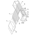
以下、図1乃至図15を参照して本発明の第1の実施の形態を説明する。図1は本実施の形態による梱包装置1の全体の構成を示す斜視図であり、まず、二つ折り手段3が設置されている。この二つ折り手段3には梱包材5が導入され、導入された梱包材5は二つ折りにされて梱包装置本体7側に搬出される。上記梱包装置本体7は、第1位置合わせ手段9、第1溶着・シール手段13、開放手段15、被梱包体搬入手段17、第2位置合わせ手段19、第2溶着・シール手段21、第3溶着・シール手段23、第1切断手段25、空気注入装置27、第2切断手段29、完成品搬送台31、適所に配置されたベルトコンベア33、等から構成されている。
Hereinafter, a first embodiment of the present invention will be described with reference to FIGS. FIG. 1 is a perspective view showing the overall configuration of the packaging device 1 according to the present embodiment. First, a bi-folding means 3 is installed. A
二つ折りされた梱包材5は、上記梱包装置本体7側において、図1中左側から右側に向けて順次搬送されていく。その際、まず、第1位置合わせ手段9によって位置合わせが行われる。次に、二つ折りされている梱包材5の搬送方向に沿った一辺に、第1溶着・シール手段13によって、溶着・シール処理が施される。次に、開放手段15によって二つ折りされた梱包材5が開放される。
尚、上記開放手段15の一例として、波形の板材を上記二つ折りされた梱包材5に挿し込むことにより開放する構成が考えられる。
The folded
As an example of the opening means 15, a configuration in which a corrugated plate material is opened by being inserted into the folded
次に、上記被梱包体搬入手段17によって被梱包体35が二つ折りされた梱包材5の中に搬入される。
尚、上記被梱包体搬入手段17の一例として、ターンテーブルを使用したものが考えられる。
Next, the packed
In addition, as an example of the packaged body carrying-in
次に、第2位置合わせ手段19によって位置合わせが行われる。次に、第2溶着・シール手段21によって上記二つ折りされた梱包材5の搬送方向に沿った他の一辺が溶着・シールされる。次に、上記第3溶着・シール手段23によって搬送方向に平行な一辺(上記被梱包体35が搬入された側の一辺)が溶着・シールされる。これによって被梱包体35が搬入された袋部5′が封止・隔離される。
Next, alignment is performed by the second alignment means 19. Next, the other side along the conveying direction of the folded
次に、第1切断手段25により搬送方向に沿った溶着・シール部位が部分的(左右両端部を残した中央部)に切断される。次に、空気注入装置27によって梱包材5を構成する複数の空気セル内に空気が注入される。次に、上記第2切断手段29によって上記第1切断手段25による切断処理で残った左右両端部が切断されて上記袋部5′が切り離される。切り離された袋部5′は完成品搬送台31上に搬出される。
Next, the first cutting means 25 cuts the weld / seal site along the transport direction partially (the central part leaving the left and right ends). Next, air is injected into a plurality of air cells constituting the packing
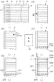
上記梱包材5は、図2に示すように、二枚のシート41a、41bを重ねて両側部を溶着・シールした構成になっている。図2(a)中溶着・シール部を符号43、43で示す。又、上記シート41a、41bの間には複数個の空気セル45が形成されている。空気セル45相互間は溶着・シール部47によって区画されている。又、上記各空気セル45の図2(a)中左端には逆止弁49がそれぞれ介挿されている。又、上記二枚のシート41a、41bの左端には空気注入管挿入孔51が形成されている。
As shown in FIG. 2, the packing
上記逆止弁49は、図2(b)に示すように、2枚のシート61a、61bを重ね合わせて適所に溶着・シール処理を施すことにより、逆止部63、65を形成した構成になっている。図中溶着・シール部を符号67、69、71、73、75、77で示す。そして、後述する空気注入管を上記空気注入管挿入孔51内に挿し込んで空気を注入することにより、各逆止弁49を介して各空気セル45内に空気が注入される。注入された空気は逆止弁49の作用により外に漏れることはない。
As shown in FIG. 2B, the
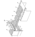
次に、上記空気注入装置27の構成を詳細に説明する。図3、図6に示すように、まず、外筐81があり、この外筐81内には梱包材位置決め・ガイド手段83が設置されている。袋部5′はこの梱包材位置決め・ガイド手段83によって所定の位置に位置決めされると共にガイド・搬送される。上記梱包材位置決め・ガイド手段83は、駆動モータ85と、駆動伝達機構87と、上記袋部5′の端を挟んで搬送するローラ機構89と、から構成されている。
尚、上記袋部5′は、図5に示すように、複数個のベルトコンベア33によって搬送される。
Next, the configuration of the
The bag portion 5 'is conveyed by a plurality of
上記駆動伝達機構87は、上記駆動モータ85の回転軸85aに固着された駆動プーリ91と、この駆動プーリ91に対して離間・配置された従動プーリ93と、複数組(この実施の形態の場合には4組)の従動プーリ対95と、タイミングベルト97と、から構成されている。上記従動プーリ対95は一対の従動プーリ99、99から構成されている。上記各従動プーリ99、99はシャフト101、101に固着されている。
The
一方、上記ローラ機構89は複数組(この実施の形態の場合には4組)のローラ対111から構成されている。上記ローラ対111は一対のローラ113、113から構成されていて、これらローラ113、113は上記シャフト101、101に固着されている。
On the other hand, the
そして、上記駆動モータ85が正転することにより、上記駆動伝達機構87を介して4組のローラ対111が適宜の方向に回転し、それによって、袋部5′がその端を上記4組のローラ対111によって挟持された状態で位置決め・ガイドされて図4中左側から右側に搬送されていく。
尚、袋部5′が詰まってしまったような場合には上記駆動モータ85を逆転させる。
Then, when the
When the bag portion 5 'is clogged, the
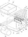
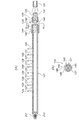
上記各ローラ対111の一対のローラ113、113の間には空気注入管121が設置されている。上記空気注入管121の先端は閉塞されているとともに、図11、図12に示すように、先端に向かって円錐状に縮径されている。又、上記空気注入管121の基端は流量調整弁123に連結されている。又、上記流量調整弁123には空気供給配管125が連結されていて、この空気供給配管125はコンプレッサ127に連結されている。又、上記空気供給配管125には電磁弁付減圧弁126が介挿されている。遠隔配置された制御盤によって上記電磁弁付減圧弁126を制御することにより注入される空気の吐出圧力を減圧する。
An
又、上記空気注入管121には複数個の空気注入孔129が形成されている。上記空気注入孔129は横長に形成されていて、隣接する空気注入孔相互間にはスリット131が形成されている。空気は上記空気注入孔129から注入されるとともに上記スリット131からも注入される。
In addition, a plurality of air injection holes 129 are formed in the
上記空気注入管121の基端には安全弁133が設けられている。すなわち、上記空気注入管121の基端内周面には雌ねじ部135が形成されている。一方、プラグ137が設置されていて、このプラグ137には雄ねじ部139が形成されている。又、上記プラグ137には上記空気供給配管125が接続されている。上記プラグ137はその雄ねじ部139を上記雌ねじ部135に螺合することにより空気注入管121に螺合・連結されている。
A
又、上記空気注入管121には吸・排気口140、140が180°の位置に対向・形成されている。又、上記空気注入管121の上記吸・排気口140、140を挟んで軸方向両側の外周部には雄ねじ部142が形成されていて、一方、カップリング144が設置されていて、このカップリング144の内周面には雌ねじ部146が形成されている。上記カップリング144はその雌ねじ部146を上記雄ねじ部142に螺合することより軸方向に移動可能に構成されている。そして、上記カップリング144を軸方向に移動させて上記吸・排気口140、140を適宜閉塞することにより、安全弁133の機能圧力を調整する。
The
すなわち、上記プラグ137を介して上記眞空気注入管121内に空気を注入すると上記吸・排気口140、140に負圧が発生し、それによって、外部の空気が吸引される。一方、空気注入管121を介して複数の空気セル内に空気が注入されて所定の圧力になると、上記吸・排気口140、140を介して余計な空気が排気される。それによって、空気セル45の不用意な破裂を防止するようにしている。
That is, when air is injected into the soot-
又、図7、図9に示すように、上記空気注入管121の基部であって上記筐体81側にはカッター141が設置されている。このカッター141によって上記袋部5′側の空気注入管挿入孔51の端を切断し、それによって、袋部5′の空気注入管71からの離脱を可能にしている。
As shown in FIGS. 7 and 9, a
又、図5に示すように、本実施の形態の場合には、複数個のベルトコンベア33の内上記空気注入装置27の手前にあるベルトコンベア33はリニアガイド151、151を介して昇降可能に構成されている。すなわち、上記ベルトコンベア33は基台153に設置されていて、この基台153の左右には上記リニアガイド151、151がそれぞれ設置されている。上記リニアガイド151はガイドレール155と、このガイドレール155に移動可能に係合されたガイド157、157と、から構成されている。上記ガイド157、157は上記基台153に固着されている。
As shown in FIG. 5, in the case of the present embodiment, the
又、アクチュエータ161が設置されていて、このアクチュエータ161は駆動モータ163と、この駆動モータ163により回転せられる楕円形の送り駒165と、から構成されている。上記送り駒165は上記基台153の下方に設置されている。上記駆動モータ163を駆動することにより上記送り駒165を回転させ、上記基台153を所定の範囲で昇降させる。それによって、袋部5′の空気注入管挿入孔51と空気注入管121の高さにバラツキがあっても解消され、空気注入管51が空気注入管121の先端によって破損してしまうようなことを防止している。例えば、袋部5′の空気注入管挿入孔51と空気注入管121の高さにバラツキがあると、空気注入管121の先端が空気注入管挿入孔51の内壁の特定の場所に当たったままになってこれを破損させてしまうことが懸念されるが、そのような事象が解消される。
An
上記外筐81の正面は図13に示すような構成になっている。まず、圧力調整摘み181が設置されていて、この圧力調整摘み181を適宜の方向に回転・操作することにより流量調整弁123の開度を調整し、それによって、注入される空気の圧力が調整される。又、圧力は圧力計183によって表示される。
The front surface of the
又、ON/OFF摘み185があり、このON/OFF摘み185を適宜操作することにより、駆動モータ85をON/OFFする。又、速度調整摘み187があり、この速度調整摘み187を適宜操作することにより駆動モータ85の回転速度を調整する。駆動モータ85の速度は速度表示部189に表示される。さらに、正転釦191、逆転釦193が設置されている。
Further, there is an ON /
又、図5に示すように、上記外筐81には超音波振動板195が設置されていて、この超音波振動板195には駆動装置197から電圧が印加される構成になっている。これによって、空気注入装置27全体に超音波振動が付与される。それによって、袋部5′の空気注入管挿入孔51と空気注入管121の高さにバラツキがあっても解消され、空気注入管51が空気注入管121の先端によって破損してしまうようなことを防止している。例えば、袋部5′の空気注入管挿入孔51と空気注入管121の高さにバラツキがあると、空気注入管121の先端が空気注入管挿入孔51の内壁の特定の場所に当たったままになってこれを破損させてしまうことが懸念されるが、そのような事象が解消される。
Further, as shown in FIG. 5, the the
次に、図14及び図15を参照して作用を説明する。
まず、図14(a)に示すように、梱包材5が梱包装置1の二つ折り手段3に導入される。導入された梱包材5は二つ折り手段3によって二つ折りにされ、図14(b)に示すような状態になる。二つ折りされた梱包材5は梱包装置本体7側に導入され、複数のベルトコンベア33によって図1中左側から右側に向けて順次搬送されていく。
Next, the operation will be described with reference to FIGS.
First, as shown in FIG. 14A, the packing
次に、図14(c)に示すように、二つ折りされた梱包材5は第1位置合わせ手段9によって位置合わせされた後、その搬送方向に沿った一辺は、第1溶着・シール手段13によって溶着・シールされる。図中溶着・シール部を符号221で示す。上記溶着・シール部221は二つの溶着・シール線211a、211bから構成されている。
Next, as shown in FIG. 14 (c), the folded
次に、図14(d)に示すように、上記梱包材5が開放手段15によって開放される。次に、図14(e)に示すように、上記開放された梱包材5内に被梱包体35が被梱包体搬入手段17によって搬入される。
次に、図14(f)に示すように、第2溶着・シール手段21によって、上記二つ折りされた梱包材5の搬送方向に沿った他の一辺が溶着・シールされる。図中溶着・シール部を符号225で示す。上記溶着・シール部225は二つの溶着・シール線225a、225bから構成されている。
次に、第3溶着・シール手段23によって梱包材5の搬送方向に平行な一辺が溶着・シールされる。図中溶着・シール部を符号223で示す。これによって、被梱包体105が搬入された袋部5′が封止・区画される。
Next, as shown in FIG. 14 (d), the packing
Next, as shown in FIG. 14 (f), the other side along the conveying direction of the folded
Next, one side parallel to the conveying direction of the packing
次に、図15(a)に示すように、第1切断手段25により搬送方向に沿った溶着・シール部位が左右両端部を残して切断される。図5(a)中切断部分を実線で示す。
次に、袋部5′の各空気セル35内に空気が注入される。すなわち、搬送されてくる袋部5′の空気注入管挿入孔51内には空気注入管121が挿し込まれていて(装置セット時に梱包材5の先端の空気抽入管挿入孔51内に空気注入管121が挿し込まれる)、その空気注入管121の複数個の空気注入孔129、スリット131を介して、上記袋部5′の各空気セル45内に空気が注入される。その際、上記空気注入管挿入孔51の端はカッター141によって切断される。それによって、梱包材5の空気注入管121からの離脱が可能になる。又、空気注入装置27の手前のベルトコンベア33は昇降動作されているとともに、空気注入装置27には超音波振動が付与されているので、袋部5′の空気注入管挿入孔51と空気注入管121の高さにバラツキがあっても効果的に解消され、上記空気注入管121によって空気注入管挿入孔51が破損されてしまうようなことはない。
Next, as shown in FIG. 15A, the first cutting means 25 cuts the welding / seal sites along the transport direction, leaving both left and right ends. The cut portion in FIG. 5 (a) is shown by a solid line.
Next, air is injected into each
次に、図15(b)に示すように、第2切断手段29によって、残された左右両端部が切断されて、先端の袋部5′が梱包材5から切り離される。これによって、一連の梱包処理が終わり、図15(c)に示す切り離された梱包体内臓の袋部5′は適所に搬送され、図示しない運搬車両による運搬に処される。
Next, as shown in FIG. 15 (b), the left and right end portions are cut by the second cutting means 29 and the leading
以上、本実施の形態によると次のような効果を奏することができる。
まず、梱包材5の複数個の空気セル45内に空気を、均一の空気圧で、且つ、効率良く注入することができる。これは空気注入管121に複数個の空気注入孔129を所定の等ピッチで形成したからであり、又、これら複数個の空気注入孔129相互間にスリット131を形成したからであり、これら複数個の空気注入孔129と複数個のスリット131を介して空気を注入するようにしたからである。
又、上記空気注入孔129が横長に形成されていることも、上記効果を得ることに大きく寄与している。
又、上記空気注入管121は梱包材5をガイドするガイド部材としても機能しているので、梱包材5が搬送途中で捩れてしまうようなこともない。
又、空気注入装置27の手前のベルトコンベア33を昇降動作させるように構成したとともに、空気注入装置27に超音波振動板195を介して超音波振動が付与されるように構成されているので、袋部5′の空気注入管挿入孔51と空気注入管121の高さにバラツキがあっても効果的に解消され、上記空気注入管121によって空気注入管挿入孔51が破損されてしまうようなことはない。
As described above, according to the present embodiment, the following effects can be obtained.
First, air can be efficiently injected into the plurality of
Further, the fact that the
Further, since the
In addition, the
次に、図16を参照して本発明の第2の実施の形態を説明する。前記第1の実施の形態の場合には、空気注入装置27の手前のベルトコンベア33を昇降可能に構成したが、この第2の実施の形態の場合には、空気注入装置27を昇降可能に構成したものである。すなわち、図16に示すように、上記空気注入装置19がリニアガイド201、201を介して昇降可能に構成されている。すなわち、上記空気注入装置27の外筐81にはリニアガイド201、201が設置されている。上記リニアガイド201はガイドレール203と、このガイドレール203に移動可能に係合されたガイド205、205とから構成されている。上記ガイド205、205は上記外筐81に固着されている。
Next, a second embodiment of the present invention will be described with reference to FIG. In the case of the first embodiment, the
又、アクチュエータ207が設置されていて、このアクチュエータ207は駆動モータ209と、この駆動モータ209により回転せられる楕円形の送り駒211と、から構成されている。上記送り駒211は上記外筐81の下方に設置されている。上記駆動モータ209を駆動することにより上記送り駒211を回転させ、上記外筐81を所定の範囲で昇降させる。それによって、空気注入管121による袋部5′の空気注入管挿入孔51の破損を防止する。
尚、その他の構成は前記第1の実施の形態の構成と同じであり、図中同一部分には同一符号を付して示しその説明は省略する。
An
The other configurations are the same as those of the first embodiment, and the same portions are denoted by the same reference numerals in the drawings, and the description thereof is omitted.
よって、前記第1の実施の形態の場合と同様の効果を奏することができる。 Therefore, the same effect as in the case of the first embodiment can be obtained.
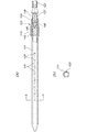
次に、図17を参照して本発明の第3の実施の形態を説明する。この第3の実施の形態の場合には、空気注入管21の先端部211を別体とし、この先端部211をコイルスプリング213を介して取り付けたものである。
その他の構成は前記第1の実施の形態の場合と同じであり、図中同一部分には同一符号を付して示しその説明は省略する。
Next, a third embodiment of the present invention will be described with reference to FIG. In the case of the third embodiment, the
Other configurations are the same as those of the first embodiment, and the same portions are denoted by the same reference numerals in the drawings, and the description thereof is omitted.
上記構成によると前記第1の実施の形態の場合と同様の作用・効果を奏することができる。又、空気注入管121の先端部211を別体としてコイルスプリング213を介して移動可能に取り付けたので、空気注入管121と空気注入管挿入孔51の高さにバラツキがあってもそれを吸収することができ、それによっても、空気注入管121による袋部5′の空気注入管挿入孔51の破損を防止する。
According to the above configuration, the same operation and effect as in the case of the first embodiment can be obtained. In addition, since the
尚、本発明は前記第1乃至第3の実施の形態に限定されるものではない。
まず、前記一実施の形態の場合には、被空気注入材として梱包材を例に挙げて説明したが、緩衝材についても同様に適用可能であり、要は複数個の空気セルを備えたものであれば対象となる。
又、空気注入管に設けられる複数個の空気注入孔の形状、個数、大きさ、ピッチ、等については様々なものが考えられる。
又、空気注入管に設けられるスリットについても同様である。
又、空気注入装置において袋部位置決め・ガイド手段、空気注入管、被空気注入材切断手段、の構成としては様々な構成が考えられる。例えば、前記第1〜第3の実施の形態では被空気注入材切断手段として平刃状のカッターを用いたが、円形刃、その他の形状の刃でもよく、又、熱線等によって溶断するようなものでもよい。
その他、図示した構成はあくまで一例である。
The present invention is not limited to the first to third embodiments.
First, in the case of the above-described embodiment, the packing material is described as an example of the air injecting material. If so.
Various shapes, numbers, sizes, pitches, and the like of the plurality of air injection holes provided in the air injection pipe are conceivable.
The same applies to the slits provided in the air injection pipe.
In the air injecting apparatus, various configurations are conceivable as the configuration of the bag positioning / guide means, the air injecting pipe, and the air injecting material cutting means. For example, in the first to third embodiments, a flat blade-shaped cutter is used as the air injection material cutting means. However, a circular blade or other shape blade may be used, and it may be melted by heat rays or the like. It may be a thing.
In addition, the illustrated configuration is merely an example.
本願発明は、例えば、梱包時に使用される緩衝材、梱包材に空気を注入する空気注入装置とその空気注入装置を使用した梱包装置に係り、特に、空気を均一に、且つ、効率良く注入することができるように工夫したものに関し、例えば、例えば、卵、豆腐、野菜、果物、牛乳といった断熱材を必要とする飲食物や衣類、調度品といった生活用品或いは壊れ易い電子部品及び精密機器、半導体等の物品を被梱包体として収容する場合に使用される緩衝材、梱包材に好適である。 The present invention relates to, for example, a cushioning material used at the time of packing, an air injection device for injecting air into the packing material, and a packing device using the air injection device, and in particular, injects air uniformly and efficiently. For example, for example, food, food, clothing, and furniture that require heat insulation such as eggs, tofu, vegetables, fruits, and milk, or fragile electronic parts and precision instruments, semiconductors, etc. It is suitable for a cushioning material and a packing material that are used when an article such as a package is accommodated as a packaged body.
1 梱包装置
5 梱包材(被空気注入材)
5′ 袋部(被空気注入材)
7 装置本体
9 第1位置合わせ手段9
13 第1溶着・シール手段
15 開放手段
17 被梱包体搬入手段
19 第2位置合わせ手段19
21 第2溶着・シール手段21
23 第3溶着・シール手段23
25 第1切断手段25
27 空気注入装置27
29 第2切断手段29
31 完成品搬送台31
33 ベルトコンベア33
45 空気セル
121 空気注入管
129 空気注入孔
131 スリット
133 安全弁
140 吸排気孔
151 リニアガイド
161 アクチュエータ
211 差込部
213 コイルスプリング(弾性部材)
141 カッター(被空気注入材切断手段)
1 Packing
5 'bag part (air-injected material)
7
13 First welding / sealing means 15 Opening means 17 Packaged article carrying means 19 Second positioning means 19
21 Second welding / sealing means 21
23 Third welding / sealing means 23
25 First cutting means 25
27
29 Second cutting means 29
31
33
45
141 cutter (air injection material cutting means)
Claims (9)
安全弁が設けられていて、
上記安全弁には吸・排気口が設けられていて、上記空気セル内に空気を注入する場合には上記吸・排気口を介して外部の空気を吸引し、上記空気セル内の圧力が所定圧力になると余計な空気が上記吸・排気口を介して排気されることを特徴とする空気注入管。 Inserted into an air injection tube insertion hole formed in an air injection material formed by connecting a plurality of air cells, and provided with a plurality of air injection holes at a predetermined pitch,
There is a safety valve,
The safety valve is provided with an intake / exhaust port, and when air is injected into the air cell, external air is sucked through the intake / exhaust port, and the pressure in the air cell is a predetermined pressure. Then, the excess air is exhausted through the intake / exhaust port.
上記空気注入孔は横長に形成されていることを特徴とする空気注入管。 The air injection tube according to claim 1, wherein
The air injection pipe is characterized in that the air injection hole is formed horizontally long.
上記複数個の空気注入孔相互間にはスリットが形成されていることを特徴とする空気注入管。 In the air injection pipe according to claim 1 or 2,
An air injection pipe, wherein a slit is formed between the plurality of air injection holes.
先端には差込部が弾性部材を介して移動可能に取り付けられていることを特徴とする空気注入管。 In the air injection pipe according to any one of claims 1 to 3,
An air injection tube characterized in that an insertion portion is attached to the tip so as to be movable via an elastic member.
上記装置本体に設置され上記搬入される被空気注入材の空気注入管挿入孔内に挿入され、複数個の空気注入孔を所定ピッチで備えていて、上記複数個の空気セル内に空気を注入する空気注入管と、
上記装置本体に設置され上記空気注入管挿入孔を切断して上記被空気注入材の上記空気注入管からの離脱を可能にする被空気注入材切断手段と、
を具備し、
上記装置本体に振動が付与されるように構成されていることを特徴とする空気注入装置。 An apparatus main body into which an air injecting material formed by connecting a plurality of air cells;
A plurality of air injection holes are provided at a predetermined pitch and are inserted into the air injection pipe insertion holes of the air injection material to be installed and carried in the apparatus main body, and air is injected into the plurality of air cells. With an air injection tube,
An air injection material cutting means installed in the apparatus main body to cut the air injection tube insertion hole and enable the air injection material to be detached from the air injection tube;
Comprising
An air injecting device characterized in that vibration is applied to the device main body.
上記被空気注入材切断手段は上記空気注入管の基部に隣接・配置されたカッターであることを特徴とする空気注入装置。 The air injection device according to claim 5, wherein
The air injecting apparatus is characterized in that the air injecting material cutting means is a cutter adjacent to and arranged at the base of the air injecting tube.
上記装置本体は所定範囲で上下動するように構成されていることを特徴とする空気注入装置。 In the air injecting device according to claim 5 or 6 ,
An apparatus for injecting air, wherein the apparatus main body is configured to move up and down within a predetermined range.
上記梱包材をシールして上記被梱包体が搬入された袋部を形成する溶着・シール手段と、
上記袋部を構成する空気セル内に空気を注入する請求項5〜請求項7の何れかに記載の空気注入装置と、
上記袋部を切り離す切断手段と、
を具備したことを特徴とする梱包装置。 To-be-packed body carrying means for carrying the to-be-packaged body inside the folded packaging material,
Welding / sealing means for sealing the packing material to form a bag part into which the packaged body is carried;
The air injecting device according to any one of claims 5 to 7, which injects air into an air cell constituting the bag portion,
Cutting means for separating the bag portion;
A packaging apparatus comprising:
上記空気注入装置の手前で上記袋部を所定範囲で上下動させるようにしたことを特徴とする梱包装置。 The packaging device according to claim 8,
A packaging device, wherein the bag portion is moved up and down within a predetermined range before the air injecting device.
Priority Applications (1)
| Application Number | Priority Date | Filing Date | Title |
|---|---|---|---|
| JP2017229499A JP6608902B2 (en) | 2017-11-29 | 2017-11-29 | Air injection tube, air injection device and packing device |
Applications Claiming Priority (1)
| Application Number | Priority Date | Filing Date | Title |
|---|---|---|---|
| JP2017229499A JP6608902B2 (en) | 2017-11-29 | 2017-11-29 | Air injection tube, air injection device and packing device |
Publications (2)
| Publication Number | Publication Date |
|---|---|
| JP2019098562A JP2019098562A (en) | 2019-06-24 |
| JP6608902B2 true JP6608902B2 (en) | 2019-11-20 |
Family
ID=66975177
Family Applications (1)
| Application Number | Title | Priority Date | Filing Date |
|---|---|---|---|
| JP2017229499A Active JP6608902B2 (en) | 2017-11-29 | 2017-11-29 | Air injection tube, air injection device and packing device |
Country Status (1)
| Country | Link |
|---|---|
| JP (1) | JP6608902B2 (en) |
Families Citing this family (1)
| Publication number | Priority date | Publication date | Assignee | Title |
|---|---|---|---|---|
| CN113578677B (en) * | 2021-09-28 | 2021-12-07 | 江苏鑫埭信息科技有限公司 | Electronic equipment conveying mechanism based on Internet of things |
-
2017
- 2017-11-29 JP JP2017229499A patent/JP6608902B2/en active Active
Also Published As
| Publication number | Publication date |
|---|---|
| JP2019098562A (en) | 2019-06-24 |
Similar Documents
| Publication | Publication Date | Title |
|---|---|---|
| JP6113177B2 (en) | Feeding unit and method for feeding a sealed pack of injectable food | |
| EP2032442B1 (en) | Machine and method for packaging groups of products | |
| ES2480692T3 (en) | Conveyor for an article handling unit, in particular for a folding unit for the production of containers of pourable food products | |
| WO2010109727A1 (en) | Cushioning material manufacturing device, material consisting of multiple sheets to be worked, and manufacturing device for material consisting of multiple sheets to be worked | |
| JP6608902B2 (en) | Air injection tube, air injection device and packing device | |
| JP6356811B2 (en) | Transport unit for transporting sealed packs of injectable food | |
| US20220177173A1 (en) | Packaging machine for producing sealed packages | |
| JP6652504B2 (en) | Feeding unit for feeding sealed packs of injectable food | |
| US8100308B2 (en) | Apparatus for separating interconnected cushions, and assembly of such an apparatus and an apparatus for manufacturing interconnected cushions | |
| US10087008B2 (en) | Feeding unit for feeding sealed packs of pourable food products | |
| JP2019210044A (en) | Vertical packaging machine and packaging method | |
| CN109070516A (en) | For providing the method and apparatus and flexible pouch packing material of flexiplast sheet of packing meterial | |
| JP7115980B2 (en) | Jam detection device, method for detecting defective packages in filling machine, folding unit for producing packages of liquid food in filling machine, and filling machine | |
| KR101576122B1 (en) | Air injection apparatus for shock-absorbing packs | |
| JP7291372B2 (en) | packaging equipment | |
| JPS6212085B2 (en) | ||
| JP6542170B2 (en) | X-ray inspection device | |
| JP4844977B2 (en) | Article holding and transporting device for overwrapping machine | |
| JP2014534936A (en) | Transfer device for transferring a sealed package of injectable food and a method for removing a fallen sealed package from a transfer device | |
| JP6634227B2 (en) | Pillow packaging machine | |
| US20210387757A1 (en) | Apparatus and method for producing tubular packages | |
| JP2003071953A (en) | Method and apparatus for manufacturing buffer packaging material | |
| JP2018002174A (en) | Position adjustment unit | |
| EP2628683A1 (en) | Process and machine for treating capsules transferred to a packaging machine | |
| JP2023099974A (en) | Article supply device, charging/packaging device, article supply method, and charging packaging method |
Legal Events
| Date | Code | Title | Description |
|---|---|---|---|
| A621 | Written request for application examination |
Free format text: JAPANESE INTERMEDIATE CODE: A621 Effective date: 20180329 |
|
| A131 | Notification of reasons for refusal |
Free format text: JAPANESE INTERMEDIATE CODE: A131 Effective date: 20190530 |
|
| A521 | Request for written amendment filed |
Free format text: JAPANESE INTERMEDIATE CODE: A523 Effective date: 20190712 |
|
| A131 | Notification of reasons for refusal |
Free format text: JAPANESE INTERMEDIATE CODE: A131 Effective date: 20190826 |
|
| A521 | Request for written amendment filed |
Free format text: JAPANESE INTERMEDIATE CODE: A523 Effective date: 20190829 |
|
| TRDD | Decision of grant or rejection written | ||
| A01 | Written decision to grant a patent or to grant a registration (utility model) |
Free format text: JAPANESE INTERMEDIATE CODE: A01 Effective date: 20191002 |
|
| A61 | First payment of annual fees (during grant procedure) |
Free format text: JAPANESE INTERMEDIATE CODE: A61 Effective date: 20191024 |
|
| R150 | Certificate of patent or registration of utility model |
Ref document number: 6608902 Country of ref document: JP Free format text: JAPANESE INTERMEDIATE CODE: R150 |
|
| R250 | Receipt of annual fees |
Free format text: JAPANESE INTERMEDIATE CODE: R250 |
|
| R250 | Receipt of annual fees |
Free format text: JAPANESE INTERMEDIATE CODE: R250 |