JP6606797B2 - Robot endoscope system - Google Patents
Robot endoscope system Download PDFInfo
- Publication number
- JP6606797B2 JP6606797B2 JP2018500265A JP2018500265A JP6606797B2 JP 6606797 B2 JP6606797 B2 JP 6606797B2 JP 2018500265 A JP2018500265 A JP 2018500265A JP 2018500265 A JP2018500265 A JP 2018500265A JP 6606797 B2 JP6606797 B2 JP 6606797B2
- Authority
- JP
- Japan
- Prior art keywords
- endoscope
- flexible
- robot
- assembly
- endoscope system
- Prior art date
- Legal status (The legal status is an assumption and is not a legal conclusion. Google has not performed a legal analysis and makes no representation as to the accuracy of the status listed.)
- Active
Links
Images


Classifications
-
- A—HUMAN NECESSITIES
- A61—MEDICAL OR VETERINARY SCIENCE; HYGIENE
- A61B—DIAGNOSIS; SURGERY; IDENTIFICATION
- A61B1/00—Instruments for performing medical examinations of the interior of cavities or tubes of the body by visual or photographical inspection, e.g. endoscopes; Illuminating arrangements therefor
- A61B1/06—Instruments for performing medical examinations of the interior of cavities or tubes of the body by visual or photographical inspection, e.g. endoscopes; Illuminating arrangements therefor with illuminating arrangements
-
- A—HUMAN NECESSITIES
- A61—MEDICAL OR VETERINARY SCIENCE; HYGIENE
- A61B—DIAGNOSIS; SURGERY; IDENTIFICATION
- A61B1/00—Instruments for performing medical examinations of the interior of cavities or tubes of the body by visual or photographical inspection, e.g. endoscopes; Illuminating arrangements therefor
- A61B1/00064—Constructional details of the endoscope body
- A61B1/00066—Proximal part of endoscope body, e.g. handles
-
- A—HUMAN NECESSITIES
- A61—MEDICAL OR VETERINARY SCIENCE; HYGIENE
- A61B—DIAGNOSIS; SURGERY; IDENTIFICATION
- A61B1/00—Instruments for performing medical examinations of the interior of cavities or tubes of the body by visual or photographical inspection, e.g. endoscopes; Illuminating arrangements therefor
- A61B1/00064—Constructional details of the endoscope body
- A61B1/00105—Constructional details of the endoscope body characterised by modular construction
-
- A—HUMAN NECESSITIES
- A61—MEDICAL OR VETERINARY SCIENCE; HYGIENE
- A61B—DIAGNOSIS; SURGERY; IDENTIFICATION
- A61B1/00—Instruments for performing medical examinations of the interior of cavities or tubes of the body by visual or photographical inspection, e.g. endoscopes; Illuminating arrangements therefor
- A61B1/00112—Connection or coupling means
- A61B1/00121—Connectors, fasteners and adapters, e.g. on the endoscope handle
- A61B1/00128—Connectors, fasteners and adapters, e.g. on the endoscope handle mechanical, e.g. for tubes or pipes
-
- A—HUMAN NECESSITIES
- A61—MEDICAL OR VETERINARY SCIENCE; HYGIENE
- A61B—DIAGNOSIS; SURGERY; IDENTIFICATION
- A61B1/00—Instruments for performing medical examinations of the interior of cavities or tubes of the body by visual or photographical inspection, e.g. endoscopes; Illuminating arrangements therefor
- A61B1/00131—Accessories for endoscopes
- A61B1/00133—Drive units for endoscopic tools inserted through or with the endoscope
-
- A—HUMAN NECESSITIES
- A61—MEDICAL OR VETERINARY SCIENCE; HYGIENE
- A61B—DIAGNOSIS; SURGERY; IDENTIFICATION
- A61B1/00—Instruments for performing medical examinations of the interior of cavities or tubes of the body by visual or photographical inspection, e.g. endoscopes; Illuminating arrangements therefor
- A61B1/00147—Holding or positioning arrangements
- A61B1/00149—Holding or positioning arrangements using articulated arms
-
- A—HUMAN NECESSITIES
- A61—MEDICAL OR VETERINARY SCIENCE; HYGIENE
- A61B—DIAGNOSIS; SURGERY; IDENTIFICATION
- A61B1/00—Instruments for performing medical examinations of the interior of cavities or tubes of the body by visual or photographical inspection, e.g. endoscopes; Illuminating arrangements therefor
- A61B1/00147—Holding or positioning arrangements
- A61B1/0016—Holding or positioning arrangements using motor drive units
-
- A—HUMAN NECESSITIES
- A61—MEDICAL OR VETERINARY SCIENCE; HYGIENE
- A61B—DIAGNOSIS; SURGERY; IDENTIFICATION
- A61B1/00—Instruments for performing medical examinations of the interior of cavities or tubes of the body by visual or photographical inspection, e.g. endoscopes; Illuminating arrangements therefor
- A61B1/005—Flexible endoscopes
- A61B1/0051—Flexible endoscopes with controlled bending of insertion part
- A61B1/0052—Constructional details of control elements, e.g. handles
-
- A—HUMAN NECESSITIES
- A61—MEDICAL OR VETERINARY SCIENCE; HYGIENE
- A61B—DIAGNOSIS; SURGERY; IDENTIFICATION
- A61B1/00—Instruments for performing medical examinations of the interior of cavities or tubes of the body by visual or photographical inspection, e.g. endoscopes; Illuminating arrangements therefor
- A61B1/005—Flexible endoscopes
- A61B1/0051—Flexible endoscopes with controlled bending of insertion part
- A61B1/0057—Constructional details of force transmission elements, e.g. control wires
-
- A—HUMAN NECESSITIES
- A61—MEDICAL OR VETERINARY SCIENCE; HYGIENE
- A61B—DIAGNOSIS; SURGERY; IDENTIFICATION
- A61B1/00—Instruments for performing medical examinations of the interior of cavities or tubes of the body by visual or photographical inspection, e.g. endoscopes; Illuminating arrangements therefor
- A61B1/012—Instruments for performing medical examinations of the interior of cavities or tubes of the body by visual or photographical inspection, e.g. endoscopes; Illuminating arrangements therefor characterised by internal passages or accessories therefor
- A61B1/0125—Endoscope within endoscope
-
- A—HUMAN NECESSITIES
- A61—MEDICAL OR VETERINARY SCIENCE; HYGIENE
- A61B—DIAGNOSIS; SURGERY; IDENTIFICATION
- A61B1/00—Instruments for performing medical examinations of the interior of cavities or tubes of the body by visual or photographical inspection, e.g. endoscopes; Illuminating arrangements therefor
- A61B1/012—Instruments for performing medical examinations of the interior of cavities or tubes of the body by visual or photographical inspection, e.g. endoscopes; Illuminating arrangements therefor characterised by internal passages or accessories therefor
- A61B1/018—Instruments for performing medical examinations of the interior of cavities or tubes of the body by visual or photographical inspection, e.g. endoscopes; Illuminating arrangements therefor characterised by internal passages or accessories therefor for receiving instruments
-
- A—HUMAN NECESSITIES
- A61—MEDICAL OR VETERINARY SCIENCE; HYGIENE
- A61B—DIAGNOSIS; SURGERY; IDENTIFICATION
- A61B1/00—Instruments for performing medical examinations of the interior of cavities or tubes of the body by visual or photographical inspection, e.g. endoscopes; Illuminating arrangements therefor
- A61B1/04—Instruments for performing medical examinations of the interior of cavities or tubes of the body by visual or photographical inspection, e.g. endoscopes; Illuminating arrangements therefor combined with photographic or television appliances
-
- A—HUMAN NECESSITIES
- A61—MEDICAL OR VETERINARY SCIENCE; HYGIENE
- A61B—DIAGNOSIS; SURGERY; IDENTIFICATION
- A61B34/00—Computer-aided surgery; Manipulators or robots specially adapted for use in surgery
- A61B34/30—Surgical robots
-
- A—HUMAN NECESSITIES
- A61—MEDICAL OR VETERINARY SCIENCE; HYGIENE
- A61B—DIAGNOSIS; SURGERY; IDENTIFICATION
- A61B1/00—Instruments for performing medical examinations of the interior of cavities or tubes of the body by visual or photographical inspection, e.g. endoscopes; Illuminating arrangements therefor
- A61B1/00002—Operational features of endoscopes
- A61B1/00011—Operational features of endoscopes characterised by signal transmission
- A61B1/00013—Operational features of endoscopes characterised by signal transmission using optical means
-
- A—HUMAN NECESSITIES
- A61—MEDICAL OR VETERINARY SCIENCE; HYGIENE
- A61B—DIAGNOSIS; SURGERY; IDENTIFICATION
- A61B1/00—Instruments for performing medical examinations of the interior of cavities or tubes of the body by visual or photographical inspection, e.g. endoscopes; Illuminating arrangements therefor
- A61B1/00131—Accessories for endoscopes
- A61B1/00135—Oversleeves mounted on the endoscope prior to insertion
-
- A—HUMAN NECESSITIES
- A61—MEDICAL OR VETERINARY SCIENCE; HYGIENE
- A61B—DIAGNOSIS; SURGERY; IDENTIFICATION
- A61B1/00—Instruments for performing medical examinations of the interior of cavities or tubes of the body by visual or photographical inspection, e.g. endoscopes; Illuminating arrangements therefor
- A61B1/005—Flexible endoscopes
-
- A—HUMAN NECESSITIES
- A61—MEDICAL OR VETERINARY SCIENCE; HYGIENE
- A61B—DIAGNOSIS; SURGERY; IDENTIFICATION
- A61B1/00—Instruments for performing medical examinations of the interior of cavities or tubes of the body by visual or photographical inspection, e.g. endoscopes; Illuminating arrangements therefor
- A61B1/04—Instruments for performing medical examinations of the interior of cavities or tubes of the body by visual or photographical inspection, e.g. endoscopes; Illuminating arrangements therefor combined with photographic or television appliances
- A61B1/044—Instruments for performing medical examinations of the interior of cavities or tubes of the body by visual or photographical inspection, e.g. endoscopes; Illuminating arrangements therefor combined with photographic or television appliances for absorption imaging
-
- A—HUMAN NECESSITIES
- A61—MEDICAL OR VETERINARY SCIENCE; HYGIENE
- A61B—DIAGNOSIS; SURGERY; IDENTIFICATION
- A61B17/00—Surgical instruments, devices or methods, e.g. tourniquets
- A61B2017/00477—Coupling
-
- A—HUMAN NECESSITIES
- A61—MEDICAL OR VETERINARY SCIENCE; HYGIENE
- A61B—DIAGNOSIS; SURGERY; IDENTIFICATION
- A61B34/00—Computer-aided surgery; Manipulators or robots specially adapted for use in surgery
- A61B34/30—Surgical robots
- A61B2034/301—Surgical robots for introducing or steering flexible instruments inserted into the body, e.g. catheters or endoscopes
-
- A—HUMAN NECESSITIES
- A61—MEDICAL OR VETERINARY SCIENCE; HYGIENE
- A61B—DIAGNOSIS; SURGERY; IDENTIFICATION
- A61B34/00—Computer-aided surgery; Manipulators or robots specially adapted for use in surgery
- A61B34/30—Surgical robots
- A61B2034/302—Surgical robots specifically adapted for manipulations within body cavities, e.g. within abdominal or thoracic cavities
-
- A—HUMAN NECESSITIES
- A61—MEDICAL OR VETERINARY SCIENCE; HYGIENE
- A61B—DIAGNOSIS; SURGERY; IDENTIFICATION
- A61B34/00—Computer-aided surgery; Manipulators or robots specially adapted for use in surgery
- A61B34/30—Surgical robots
- A61B34/37—Master-slave robots
-
- A—HUMAN NECESSITIES
- A61—MEDICAL OR VETERINARY SCIENCE; HYGIENE
- A61B—DIAGNOSIS; SURGERY; IDENTIFICATION
- A61B34/00—Computer-aided surgery; Manipulators or robots specially adapted for use in surgery
- A61B34/70—Manipulators specially adapted for use in surgery
- A61B34/71—Manipulators operated by drive cable mechanisms
Description
本発明は、本体と可撓性の細長いシャフトを有する、可撓性のある拡張ロボット内視鏡装置に関する。本体は、そこを通して複数の内視鏡機具チャンネルが利用しやすい複数の挿入インレットを備えた近端を有するハウジングを含んでいる。そして、可撓性の細長いシャフトは、本体の遠端から離れるように遠端に延びる近端と、前記インレットを介して可撓性のある細長いシャフトの複数のチャンネルに挿入可能な可撓性のある細長いアセンブリの部分を保持するためのそれらの間の複数のチャンネルを有する。 The present invention relates to a flexible extended robot endoscope apparatus having a main body and a flexible elongated shaft. The body includes a housing having a proximal end with a plurality of insertion inlets through which a plurality of endoscopic instrument channels are accessible. The flexible elongate shaft is a flexible end that can be inserted into a plurality of channels of the flexible elongate shaft through the inlet and a proximal end extending to the far end away from the distal end of the main body. It has a plurality of channels between them for holding a portion of an elongated assembly.
外科手術用のロボット工学は、外科的手法において、特に、低侵襲性外科手術において大きな変革をもたらした。可撓性のあるロボット内視鏡の出現が、自然開口部越経管腔的内視鏡手術(NOTES)又は身体への経皮的なアクセスサイトを必要としない「非切開」外科手術処理のような処置を可能にしたが、それによって、可撓性のあるロボット内視鏡が被術者の口のような、被術者の自然開口部に挿入され、そして、更に、内視鏡の遠端が被術者の内部の関心のある目的サイトに位置するか若しくはそれに非常に近くなるまで被術者の消化管の部分のような自然内部通路内又はそれに沿って操縦されている。一旦内視鏡の遠端がその目的のサイトに位置すると、外科的処理が、内視鏡によって保持される一又はそれ以上のロボットアームと対応するエンドエフェクタにより行われ、そして、それは制御卓と外科医の相互作用に応じてロボット制御の基で、内視鏡の遠端を越えて移動及び操作可能である。マスタースレーブ型の可撓性のあるロボット内視鏡システムの代表的な例が、以下に記載されている。 Surgical robotics has revolutionized surgical procedures, particularly in minimally invasive surgery. The emergence of flexible robotic endoscopy is not a natural opening transluminal endoscopic surgery (NOTES) or “non-incision” surgical procedure that does not require a percutaneous access site to the body. Such that a flexible robot endoscope is inserted into the natural opening of the subject, such as the subject's mouth, and further, the endoscope's It is steered in or along a natural internal passage such as a portion of the subject's digestive tract until the far end is located at or very close to the target site of interest inside the subject. Once the distal end of the endoscope is located at its intended site, the surgical process is performed by one or more robot arms held by the endoscope and corresponding end effectors, which can be It can be moved and manipulated beyond the far end of the endoscope under robot control in response to surgeon interaction. A typical example of a master-slave type flexible robot endoscope system is described below.
現状の可撓性のあるロボット内視鏡システムにおいて、ロボットアームと対応するエンドエフェクタのような多くの可撓性のある内視鏡機器又は機器アセンブリと、該エンドエフェクタの画像を取り込む撮像アセンブリプローブが知られている。この可撓性のある内視鏡機器は使い捨て可能であり、可撓性のあるロボット内視鏡システムに挿入可能であり、又は、可撓性のあるロボット内視鏡システムから取り出し可能である。 In current flexible robotic endoscope systems, many flexible endoscopic devices or device assemblies, such as end effectors associated with robotic arms, and imaging assembly probes that capture images of the end effectors It has been known. The flexible endoscopic device is disposable and can be inserted into or removed from the flexible robotic endoscope system.
手術室内において、可撓性のあるロボット内視鏡システムをセットアップ/組み立て及び分解の便宜と速度を強化又は最大にすることが望ましいが、同時に、システムがセットアップされる全般的な態様がシステムのロボット要素に対する非常に正確な空間的及び時間的な制御を可能にすることを確実にすることが望ましい。更に、手術室の状況において、臨床医は、新しい可撓性のある内視鏡機器を早急に取り付ける、若しくは、現在取り付けられている可撓性のある内視鏡機器を新しい又は他のタイプの可撓性のある内視鏡機器に交換する必要がある。 While it is desirable to enhance or maximize the convenience and speed of setting up / assembling and disassembling a flexible robotic endoscope system within an operating room, at the same time the general manner in which the system is set up is the robot of the system It is desirable to ensure that very precise spatial and temporal control over the elements is possible. Further, in the operating room situation, the clinician can quickly install a new flexible endoscopic instrument, or install a new or other type of flexible endoscopic instrument that is currently installed. It is necessary to replace the endoscope device with a flexible one.
残念なことに、既存のシステムは、可撓性のある内視鏡システムがセットアップされる態様の影響、可撓性のある内視鏡機器が可撓性のある内視鏡システムに挿入され、それを通る態様の影響、及び、内視鏡機器の内部の結果的な力がシステムの能力に対して最大の精度でもってエンドエフェクタを信頼性よく空間的に及び時間的に制御しなければならないことを適切に考慮してはいない。 Unfortunately, the existing system is influenced by the manner in which the flexible endoscope system is set up, the flexible endoscope instrument is inserted into the flexible endoscope system, The effect of the way through it and the resulting forces inside the endoscopic instrument must reliably and spatially and temporally control the end effector with maximum accuracy for the system's capabilities. This is not considered properly.
請求項1に記載の本願発明は、ロボット内視鏡装置であり、該ロボット内視鏡装置は、近端と遠端と該近端に延在するハウジングとからなる本体であって、該ハウジングが複数の面と、そこを通して複数の内視鏡用のチャンネルが利用可能である、前記本体の近端において前記ハウジングの表面のうち少なくとも一つの面に存在する複数の挿入インレットとを有する本体と、前記本体の遠端から離間して延びる近端を有する可撓性のある細長いシャフトであって、遠端と中心軸と可撓性のある細長いアセンブリの部分を保持する、その内部の複数のチャンネルと、該複数のチャンネルのそれぞれに対して可撓性のある細長いシャフトの遠端に配設される開口部を有する可撓性のある細長いシャフトとからなり、前記挿入インレットのそれぞれがそれに対応する挿入軸を有し、それに沿って可撓性のある細長いアセンブリが挿入可能であり、前記挿入インレットの挿入軸が可撓性のある細長いシャフトの近端において可撓性のある細長いシャフトの中心軸と平行である。 The present invention according to claim 1 is a robot endoscope apparatus, and the robot endoscope apparatus is a main body including a near end, a far end, and a housing extending to the near end, the housing A body having a plurality of surfaces and a plurality of insertion inlets present in at least one of the surfaces of the housing at a proximal end of the body through which a plurality of endoscope channels are available. A flexible elongate shaft having a proximal end extending away from a distal end of the body, the plurality of internal shafts holding a distal end, a central axis, and a portion of the flexible elongate assembly; A flexible elongated shaft having an opening disposed at a distal end of the flexible elongated shaft with respect to each of the plurality of channels, and each of the insertion inlets. A flexible elongate shaft having a corresponding insertion axis along which a flexible elongate assembly can be inserted, the insertion axis of the insertion inlet being flexible at the proximal end of the flexible elongate shaft Is parallel to the central axis.
請求項2に記載の本願発明は、請求項1に記載のロボット内視鏡装置において、複数のインレットが複数の面のうちの一つに一列に配設されている特徴を有する。 According to a second aspect of the present invention, in the robot endoscope apparatus according to the first aspect, the plurality of inlets are arranged in a line on one of the plurality of surfaces.
請求項3に記載の本願発明は、請求項1に記載のロボット内視鏡装置において、ロボット内視鏡装置が、更に、前記内視鏡装置の可撓性のある細長いシャフトを介して、通気、陽圧、吸気、負圧、真空圧、洗浄液の送出のうちの少なくとも一つを含むサポート機能のために、前記本体と外部システムを連結するように構成されたサポート機能コネクタアセンブリからなる特徴を有する。 According to a third aspect of the present invention, there is provided the robot endoscope apparatus according to the first aspect, wherein the robot endoscope apparatus is further ventilated via a flexible elongated shaft of the endoscope apparatus. A support function connector assembly configured to connect the body and an external system for support functions including at least one of positive pressure, intake air, negative pressure, vacuum pressure, and cleaning liquid delivery. Have.
請求項4に記載の本願発明は、請求項1に記載のロボット内視鏡装置において、少なくとも一つの可撓性のある細長いアセンブリが、ロボットアームと、外部作動要素によって発生された力に従って内視鏡処置を行うように構成された対応するエンドエフェクタと、前記外部作動要素から前記ロボットアームとエンドエフェクタに力を伝えるように構成された複数の緊張材要素と、該複数の緊張材要素と外部作動要素を連結するように構成されたアダプタからなる特徴を有する。 According to a fourth aspect of the present invention, there is provided the robot endoscope apparatus according to the first aspect, wherein at least one flexible elongate assembly is endoscopic according to a force generated by a robot arm and an external actuating element. A corresponding end effector configured to perform a mirror treatment, a plurality of tendon elements configured to transmit force from the external actuation element to the robot arm and end effector, the plurality of tendon elements and the external With the feature of an adapter configured to couple the actuating elements.
請求項5に記載の本願発明は、請求項4に記載のロボット内視鏡装置において、前記可撓性のある細長いアセンブリのそれぞれが、更に、複数の緊張材要素を被覆するように構成された可撓性のあるシースと、該可撓性のあるシースによって被覆された複数の緊張材要素を保持するように構成された可撓性のある細長いアウタスリーブからなる特徴を有する。 The present invention according to claim 5 is the robot endoscope apparatus according to claim 4, wherein each of the flexible elongated assemblies is further configured to cover a plurality of tendon elements. It has a feature comprising a flexible sheath and a flexible elongated outer sleeve configured to hold a plurality of tendon elements covered by the flexible sheath.
請求項6に記載の本願発明は、請求項4に記載のロボット内視鏡装置において、前記可撓性のある細長いアセンブリのそれぞれが、更に、前記エンドエフェクタの遠端から所定の距離において可撓性のある細長いアウタスリーブの少なくとも一部を囲繞するように構成されたカラー部材であって、長手方向の移動機構を噛み合わせて予め決められた距離範囲を越えた前記可撓性のある細長いアセンブリのうちの少なくとも一つの長手方向の移動を可能にするように構成されたカラー部材からなる特徴を有する。 The present invention according to claim 6 is the robot endoscope apparatus according to claim 4, wherein each of the flexible elongated assemblies is further flexible at a predetermined distance from a distal end of the end effector. A collar member configured to surround at least a portion of a flexible elongate outer sleeve, the flexible elongate assembly engaging a longitudinal movement mechanism and exceeding a predetermined distance range At least one of which has a feature comprising a collar member configured to allow longitudinal movement.
請求項7に記載の本願発明は、請求項3に記載のロボット内視鏡装置において、前記可撓性のある細長いアセンブリのうちの少なくとも一つが、前記エンドエフェクタが存在する前記可撓性のある細長いシャフトの遠端の外部の環境の画像を取り込むように構成された撮像ユニットと、前記外部作動要素を前記撮像ユニットに連結するように構成された複数の緊張材要素と、それによって該複数の緊張材要素が特定の外部作動材に連動されるアダプタからなる可撓性のある撮像内視鏡アセンブリである特徴を有する。 The present invention according to claim 7 is the robot endoscope apparatus according to claim 3, wherein at least one of the flexible elongated assemblies is the flexible where the end effector exists. An imaging unit configured to capture an image of an environment external to the distal end of the elongated shaft; a plurality of tendon elements configured to couple the external actuation element to the imaging unit; The tendon element has the feature of being a flexible imaging endoscope assembly consisting of an adapter that is linked to a specific external actuation material.
請求項8に記載の本願発明は、ロボット内視鏡システムであり、該ロボット内視鏡システムは、(a)外部作動要素によって発生された力に応じて内視鏡処置を行うように構成された少なくとも一つの可撓性のある細長いアセンブリと、(b)本体と、中心軸と少なくとも一つの可撓性のある細長いアセンブリの部分を保持するための内部の複数のチャンネルを含む可撓性のある細長いシャフトを有する輸送内視鏡と、(c)該輸送内視鏡と着脱自在に嵌合するように構成されたドッキングステーションであって、少なくとも一つの可撓性のある細長いアセンブリに嵌合して係合すると共に、少なくとも一つの可撓性のある細長いアセンブリを予め決められた距離範囲を越えて長手方向に移動するように構成された移動ユニットを有するドッキングステーションと、(d)可撓性のある細長いアセンブリのそれぞれを駆動するように構成された複数の作動器を含むモータボックスと、(e)外部制御信号に従って前記複数の作動器のそれぞれを制御するように構成された主制御ユニットとからなり、前記輸送内視鏡が、(i)少なくとも一つの可撓性のある細長いアセンブリが移動ユニットと噛合して係合するのと同じ方向、及び、(ii)可撓性のある細長いシャフトの中心軸に平行な方向のうちの何れか一つの方向からドッキングステーションと嵌合する。 The present invention according to claim 8 is a robot endoscope system, and the robot endoscope system is configured to perform an endoscope treatment in accordance with a force generated by (a) an external operating element. A flexible body including at least one flexible elongate assembly; (b) a body; and a central axis and a plurality of internal channels for holding a portion of the at least one flexible elongate assembly. A transport endoscope having an elongated shaft; and (c) a docking station configured to detachably fit with the transport endoscope, the mating fit with at least one flexible elongated assembly And at least one flexible elongated assembly having a moving unit configured to move longitudinally over a predetermined distance range. And (d) a motor box including a plurality of actuators configured to drive each of the flexible elongated assemblies; and (e) controlling each of the plurality of actuators according to an external control signal. A main control unit configured to, wherein the transport endoscope is in the same direction as (i) at least one flexible elongated assembly meshingly engaging with the moving unit; and (Ii) The docking station is fitted from any one of the directions parallel to the central axis of the flexible elongated shaft.
請求項9に記載の本願発明は、請求項8に記載のロボット内視鏡システムにおいて、ロボット内視鏡システムが、更に、前記内視鏡システムの可撓性のある細長いシャフトを介して、通気、陽圧、吸気、負圧、真空圧、洗浄液の送出のうちの少なくとも一つを含むサポート機能のために、前記本体と外部システムを連結するように構成されたサポート機能コネクタアセンブリからなる特徴を有する。 The present invention according to claim 9 is the robot endoscope system according to claim 8, wherein the robot endoscope system is further ventilated through a flexible elongated shaft of the endoscope system. A support function connector assembly configured to connect the body and an external system for support functions including at least one of positive pressure, intake air, negative pressure, vacuum pressure, and cleaning liquid delivery. Have.
請求項10に記載の本願発明は、請求項8に記載のロボット内視鏡システムにおいて、少なくとも一つの可撓性のある細長いアセンブリが、ロボットアームと、外部作動要素によって発生された力に従って内視鏡処置を行うように構成された対応するエンドエフェクタと、前記外部作動要素によって発生された力を前記ロボットアームとエンドエフェクタに伝えるように構成された複数の緊張材要素と、該複数の緊張材要素と外部作動要素を連結するように構成されたアダプタからなる作動アセンブリである特徴を有する。
The present invention according to
請求項11に記載の本願発明は、請求項8に記載のロボット内視鏡システムにおいて、前記モータボックスが、少なくとも一つのアダプタからなり、モータボックスのアダプタの一つが作動アセンブリのアダプタと連結している特徴を有する。 The present invention according to claim 11 is the robot endoscope system according to claim 8, wherein the motor box includes at least one adapter, and one of the adapters of the motor box is connected to the adapter of the operation assembly. It has the characteristics.
請求項12に記載の本願発明は、請求項11に記載のロボット内視鏡システムにおいて、前記可撓性のある細長いアセンブリのそれぞれが、更に、前記エンドエフェクタの遠端から所定に距離離れて可撓性のある細長いアウタスリーブの少なくとも一部を囲繞するように構成されたカラー部材であって、予め決められた距離範囲を越えて前記可撓性のある細長いアセンブリのうちの少なくとも一つの長手方向の移動を可能にするように構成されたカラー部材からなる特徴を有する。 The present invention according to claim 12 is the robot endoscope system according to claim 11, wherein each of the flexible elongated assemblies can further be separated from the distal end of the end effector by a predetermined distance. A collar member configured to surround at least a portion of the flexible elongate outer sleeve, the longitudinal direction of at least one of the flexible elongate assemblies beyond a predetermined distance range A feature comprising a collar member configured to allow movement of the collar member.
請求項13に記載の本願発明は、請求項12に記載のロボット内視鏡システムにおいて、前記移動ユニットが、前記カラー部材と歯合し係合して長手方向の移動を可能にするように構成された少なくとも一つのレシーバからなる特徴を有する。 According to a thirteenth aspect of the present invention, in the robot endoscope system according to the twelfth aspect, the moving unit is configured to be engaged with and engaged with the collar member so as to be movable in the longitudinal direction. And at least one receiver.
請求項14に記載の本願発明は、請求項13に記載のロボット内視鏡システムにおいて、前記可撓性のある細長いアセンブリのうちの少なくとも一つが、前記エンドエフェクタの画像を取り込むように構成された撮像ユニットと、加えられた力に応じて撮像ユニットを空間的に位置決めをするように構成された複数の緊張材要素と、それによって該可撓性のある撮像内視鏡アセンブリの複数の緊張材要素が特定の外部作動要素に連動されるアダプタからなる可撓性のある撮像内視鏡アセンブリである特徴を有する。 The present invention according to claim 14 is the robot endoscope system according to claim 13, wherein at least one of the flexible elongated assemblies is configured to capture an image of the end effector. An imaging unit, a plurality of tendon elements configured to spatially position the imaging unit in response to an applied force, and thereby a plurality of tendon members of the flexible imaging endoscope assembly The element is characterized by being a flexible imaging endoscope assembly consisting of an adapter that is linked to a specific external actuating element.
請求項15に記載の本願発明は、ロボット内視鏡システムであり、該ロボット内視鏡システムは、(a)外部制御信号に従い内視鏡処置を行うように構成された少なくとも一つの可撓性のある細長いアセンブリと、(b)近端と遠端と本体と可撓性のある細長いシャフトを有する輸送内視鏡であって、該本体が前記近端に延びるハウジングと該ハウジングの表面上のジョイント部材と前記遠端に向かうグリップとからなり、該可撓性のある細長いシャフトが中心軸と、前記少なくとも一つの可撓性のある細長いアセンブリの部分を保持するための内部の複数のチャンネルを含む輸送内視鏡と、(c)該輸送内視鏡と着脱自在に嵌合するように構成されたドッキングステーションであって、前記少なくとも一つの可撓性のある細長いアセンブリに嵌合して係合すると共に、少なくとも一つの可撓性のある細長いアセンブリを予め決められた距離範囲を越えて選択的に長手方向に移動するように構成された移動ユニットを有するドッキングステーションと、(d)可撓性のある細長いアセンブリのそれぞれを駆動するように構成された複数の作動器を含むモータボックスと、(e)外部制御信号に従って前記複数の作動器のそれぞれを制御するように構成された主制御ユニットとからなる。 The present invention according to claim 15 is a robot endoscope system, wherein the robot endoscope system is configured to perform (a) an endoscope treatment according to an external control signal. (B) a transport endoscope having a proximal end, a distal end, a body, and a flexible elongated shaft, wherein the body extends to the proximal end and on a surface of the housing A joint member and a grip toward the distal end, the flexible elongate shaft having a central axis and a plurality of internal channels for holding a portion of the at least one flexible elongate assembly. A transport endoscope comprising: (c) a docking station configured to detachably engage with the transport endoscope, the at least one flexible elongated assembly A docking station having a moving unit configured to engage and engage and to selectively move at least one flexible elongate assembly longitudinally over a predetermined distance range; (D) a motor box including a plurality of actuators configured to drive each of the flexible elongated assemblies; and (e) configured to control each of the plurality of actuators according to an external control signal. Main control unit.
請求項16に記載の本願発明は、請求項15に記載のロボット内視鏡システムにおいて、前記ハウジングの部分が立方体チューブ形状を有する特徴を有する。 According to a sixteenth aspect of the present invention, in the robot endoscope system according to the fifteenth aspect, the housing portion has a cubic tube shape.
請求項17に記載の本願発明は、請求項15に記載のロボット内視鏡システムにおいて、前記ジョイント部材が前記ハウジングの側面に形成される特徴を有する。 According to a seventeenth aspect of the present invention, in the robot endoscope system according to the fifteenth aspect, the joint member is formed on a side surface of the housing.
請求項18に記載の本願発明は、請求項15に記載のロボット内視鏡システムにおいて、前記ハウジングが、更に、近端において、そこから複数のチャンネルが利用可能な複数の挿入インレットからなる特徴を有する。 The present invention according to claim 18 is the robot endoscope system according to claim 15, wherein the housing further comprises a plurality of insertion inlets through which a plurality of channels can be used from the housing at the proximal end. Have.
請求項19に記載の本願発明は、ロボット内視鏡装置であり、該ロボット内視鏡装置は、そこから可撓性のある細長いシャフトが延びる本体を有する内視鏡であって、該可撓性のある細長いシャフトがその近端と遠端の間の長さにおいて延在し、第1と第2のチャンネルを含む長さに亘り内部に配設された複数のチャンネルを有する内視鏡と、前記可撓性のある細長いシャフトによって保持され、該可撓性のある細長いシャフトの遠端の外部の環境の画像を取り込み可能にするように構成された内視鏡撮像要素のセットであって、前記可撓性のある細長いシャフトに挿入可能であると共にそこから取り出し可能である撮像内視鏡の部分とは分離されているがそれによって保持されず、その部分を形成するものではない内視鏡撮像要素のセットと、前記第1のチャンネルに取り出し可能に挿入されるロボット駆動作動アセンブリであって、連結されたロボット駆動エンドエフェクタを有するロボットアームと加えられた力に応じてロボットアームとそのエンドエフェクタを空間的に操作するように作動自在である複数の緊張材要素を有するロボット駆動作動アセンブリと、前記第2のチャンネルに取り出し可能に挿入される手動で駆動される作動アセンブリであって、そこに連結された手動操作内視鏡機器を有する手動で駆動される作動アセンブリとからなる。 The present invention according to claim 19 is a robot endoscope apparatus, and the robot endoscope apparatus includes a main body from which a flexible elongated shaft extends, and the flexible endoscope apparatus includes the flexible endoscope. An endoscope having a plurality of channels internally disposed over a length including a first and a second channel, the elongated shaft having a length extending between a proximal end and a distal end thereof A set of endoscopic imaging elements held by the flexible elongate shaft and configured to allow capture of an image of an environment outside the distal end of the flexible elongate shaft; An endoscope that is separate from, but not held by, and does not form part of the imaging endoscope that can be inserted into and removed from the flexible elongate shaft Set of mirror imaging elements A robot drive actuating assembly removably inserted into the first channel, wherein the robot arm having a connected robot drive end effector and the robot arm and its end effector are spatially separated according to applied force. A robot driven actuation assembly having a plurality of tendon elements operable to operate, and a manually driven actuation assembly removably inserted into said second channel, wherein a manual coupled thereto And a manually driven actuation assembly having an operating endoscopic instrument.
請求項20に記載の本願発明は、請求項19に記載のロボット内視鏡装置において、前記内視鏡撮像要素のセットのうちの少なくともいくつかの内視鏡撮像要素が、前記可撓性のある細長いシャフトに対して位置的に固定されている特徴を有する。
The present invention according to
請求項21に記載の本願発明は、請求項19に記載のロボット内視鏡装置において、前記内視鏡撮像要素のセットが、前記可撓性のある細長いシャフトの遠端部内に配設された少なくとも一つの撮像センサと、一組の光ファイバと、前記可撓性のある細長いシャフトの遠端面に配設されたレンズを含む特徴を有する。 According to a twenty-first aspect of the present invention, in the robot endoscope apparatus according to the nineteenth aspect, the set of the endoscope imaging elements is disposed in a distal end portion of the flexible elongated shaft. At least one imaging sensor, a pair of optical fibers, and a lens disposed on a distal end surface of the flexible elongate shaft.
本開示の実施の形態によれば、作動アセンブリや可撓性のある撮像内視鏡アセンブリのような複数の可撓性のある細長いロボットアセンブリが、該アセンブリのロボット要素の向上した精度の高い空間的及び時間的な制御を容易にするような方法で、素早く且つ便利に輸送内視鏡とその可撓性のある細長いシャフトに挿入可能である。
本開示の実施の形態によれば、輸送内視鏡は、例えば、ジョイント部材によって、ドッキングステーションに容易に且つ確実に取り外し可能に嵌合される。輸送内視鏡の本体のグリップは、典型的には、本体の遠端に向かって配置され、ジョイント部材は本体の近端に向かって配置される。内視鏡医のような臨床医は、本体のグリップを握り、素早く且つ便利にドッキングステーションに本体を嵌合し、若しくは、そこから解除する。臨床医がその手を変えるか、又は、その手から本体のグリップを離して、ドッキングステーションと輸送内視鏡の嵌合又は解除をすることは必要ではない。
In accordance with embodiments of the present disclosure, a plurality of flexible elongated robot assemblies, such as an actuation assembly and a flexible imaging endoscope assembly, provide an improved and precise space for the robot elements of the assembly. Can be quickly and conveniently inserted into the transport endoscope and its flexible elongate shaft in a manner that facilitates automatic and temporal control.
According to the embodiment of the present disclosure, the transport endoscope is detachably fitted to the docking station easily and reliably, for example, by a joint member. The grip of the main body of the transport endoscope is typically disposed toward the distal end of the main body, and the joint member is disposed toward the proximal end of the main body. A clinician, such as an endoscopist, grasps the grip of the body and quickly or conveniently fits the body into or out of the docking station. It is not necessary for the clinician to change his hand, or to release the body grip from his hand to engage or release the docking station and transport endoscope.
本開示において、所定要素の描写又は特定の図の特定要素の番号の考慮又は使用若しくは対応する記述素材におけるその引用は、他の図で特定した同一、均等、又は類似の要素又は要素の番号若しくはそれに関連した記述素材を包摂することができる。図又は関連するテキストにおいて「/」の使用は、別段の示唆のない限り、「及び/又は」を意味するように理解される。ここで、特定の数値又は数値範囲の列挙は、おおよその数値又は数値範囲、例えば、±20%、±15%、±10%、±5%の列挙であるか、又はそれを含むと解される。 In this disclosure, the depiction of a given element or the consideration or use of a particular element number in a particular figure or its citation in corresponding descriptive material is the same, equivalent, or similar element or element number or Descriptive material related to it can be included. The use of “/” in the figures or associated text is understood to mean “and / or” unless otherwise indicated. Here, the recitation of a specific numerical value or numerical range is understood to be or include an approximate numerical value or numerical range, for example, ± 20%, ± 15%, ± 10%, ± 5%. The
ここに使用されたように、用語「セット(set)」は、(例えば、Peter J.Eccles著、Cambridge UniversityPress(1998年)刊の「An introduction Mathematical Reasoning:Numbers,Sets,andFunctions,“Chapter 11:Properties of Finite Sets”(数学的推論の導入:数、集合、関数」の第11章有限集合の属性(例えば、140頁に示されたような)に記載されたそれに対応するような態様で、)既知の数学的な定義に従い、少なくとも1の濃度を数学的に示す要素の非空の有限の組織に対応するか若しくはそれとして定義される(例えば、ここに定義されたセットは、ユニット、単一体、又は単一の要素セット若しくは多数要素セットに対応することが出来る)。一般的に、セットの要素は、考慮中のセットのタイプに依存したシステム、装置、デバイス、構造、物体、プロセス、物理的パラメータ又は値であるか若しくはそれを含むことが出来る。 As used herein, the term “set” can be found in, for example, “An introductory Material Reasoning: Numbers, C,” published by Peter J. Eccles, Cambridge University Press (1998). In a manner corresponding to that described in Chapter 11 Finite Set Attributes of “Properties of Finite Sets” (Introduction of Mathematical Reasoning: Numbers, Sets, Functions) (eg, as shown on page 140), Corresponding to or defined as a non-empty finite organization of elements mathematically representing at least one concentration according to a known mathematical definition (e.g., a set defined herein is a unit) (A single element or a single element set or multiple element sets can be supported.) Generally, the elements of a set are systems, apparatus, devices, structures, objects, processes depending on the type of set under consideration. , A physical parameter or value, or can include it.
本開示の実施の形態は、可撓性のあるマスタースレーブロボット内視鏡システムに関するが、それはマスタサイドのシステムと該マスタサイドのシステムによって制御可能か、又は、制御されるスレーブサイドのシステムを含む。また、本開示の実施の形態は、スレーブ又はスレーブサイドのシステムの拡張された機構又は構造を提供する。 Embodiments of the present disclosure relate to a flexible master-slave robot endoscope system, which includes a master-side system and a slave-side system that is controllable or controlled by the master-side system . Embodiments of the present disclosure also provide an extended mechanism or structure for a slave or slave side system.
図1A及び図1Bは、本開示の実施の形態に従った、可撓性のあるマスタースレーブロボット内視鏡システム10の略図である。実施の形態において、このシステム10は、関連するマスタサイドの要素を有するマスタ又はマスタサイドのシステム100と、関連するスレーブサイドの要素を有するスレーブ又はスレーブサイドのシステム200を含む。
1A and 1B are schematic views of a flexible master-slave
スレーブ又はスレーブサイドのシステム200に配設された内視鏡装置の遠端を示す図5に関連して、様々な実施の形態では、マスタシステム100及びスレーブシステム200は、相互の信号通信用に構成されていて、マスタシステム100は、スレーブシステム200にコマンドを発することができ、更に、スレーブシステム200は、(a)スレーブシステム200の輸送内視鏡(transport endoscope)300により保持ないし支持されるロボットアーム400a、b及び対応するエンドエフェクタ410a、bのセットと、(b)場合によってはマスタシステム入力に応じて、輸送内視鏡300により保持ないし支持される撮像内視鏡又は撮像プローブ部材460とを、正確に制御、操縦、操作/位置決め及び/作動することができる。マスタ及びスレーブシステム100、200はさらに、ロボットアーム410a、b及び/又はそれと関連するエンドエフェクタ420a〜bが位置決め、操作もしくは作動されているときに、スレーブシステム200が、触感/ハプティック(tacile/haptic)フィードバック信号(たとえば、力フィードバック信号)を、マスタシステム100に動的に提供するように構成されうる。そのような触感/ハプティックフィードバック信号は、ロボットアーム410a、b及びエンドエフェクタ420a、bが存在する環境内で、ロボットアーム410a、b及び/又はエンドエフェクタ420a〜bに与える力と関連又は対応する。
With reference to FIG. 5 showing the distal end of an endoscopic device disposed in a slave or slave-
図1A及び図1Bに戻り、本開示に従う様々な実施の形態は、手術の状況もしくは環境、たとえば、患者もしくは対象者が手術台もしくはプラットフォーム20上に置かれている間に患者もしくは対象者に対して実行される自然開口部越経管腔的内視鏡手術(NOTES)処置に関連する。そのような実施の形態では、スレーブシステム200の少なくとも部分は、手術台(OT)又は手術室(OR)内に存在するよう構成される。実施の形態の詳細に応じて、マスタシステム100は、OT/ORの内もしくは外(たとえば、近傍もしくは遠隔)に存在するものとすることができる。マスタシステム100とスレーブシステム200との間の通信は、実施の形態の詳細に応じて、(たとえば、ローカル通信ライン及び/又はローカルワイヤレス通信を通じて)直接的に、又は、一以上のネットワーク(たとえば、ローカルエリアネットワーク(LAN)、ワイドエリアネットワーク(WAN)及び/又はインターネット)により間接的に生じるものとすることができる。
Returning to FIGS. 1A and 1B, various embodiments in accordance with the present disclosure may be useful for a surgical situation or environment, such as for a patient or subject while the patient or subject is placed on an operating table or
図2は、本開示の実施の形態に従うマスタシステム100の略図である。実施の形態では、マスタシステム100は、左右のハプティック入力デバイス110a、bを搭載するフレームもしくはコンソール構造102、追加/補助の手動入力デバイス/ボタンのセット115、足操作式制御装置/ペダルのセット120a〜d、ディスプレイ装置130及び、プロセッシングモジュール150を含む。フレーム/コンソール構造102は、マスタシステム100が意図される使用環境(たとえばOT/OR又は、その外側または遠隔の部屋、)内に容易に運搬可能/配置可能になるようなホイールのセット104及び、アームサポートのセット112を含むことができる。典型的な内視鏡処置の間、外科医は、マスタシステム100に対し彼ら自身を置くか又は座って、彼らの左右の手が左右のハップティック入力デバイス110a、bを握るか、又はそれと互いに連動することができるとともに、彼らの足がペダル120a〜dと連動することができるようにする。プロセッシングモジュール150は、ハプティック入力デバイス110a、b、追加/補助の手動入力デバイス115及びペダル120a〜dから受信される信号を処理するとともに、ロボットアーム410a、b及びそれに対応するエンドエフェクタ420a〜bを操作/位置決め/制御し、また場合によっては撮像内視鏡460を操作/位置決め/制御する目的で、スレーブシステム200に、対応するコマンドを発する。プロセッシングモジュール150は、さらに、スレーブシステム200から触感/ハプティップフィードバック信号を受信し、そのような触感/ハプティップフィードバック信号を、ハプティップ入力デバイス110a、bへ伝達することができる。プロセッシングモジュール150は、計算/処理及び通信リソース(たとえば、一以上の処理装置、ランダムアクセスメモリ(RAM)、リードオンリーメモリ(ROM)を含むメモリ/データストレージリソース及び、場合によっては、一以上の種類のディスクドライブ及び、シリアル通信ユニット及び/又は、ネットワーク通信ユニット)を、関連技術における当業者により容易に理解される態様にて含む。
FIG. 2 is a schematic diagram of a master system 100 according to an embodiment of the present disclosure. In an embodiment, the master system 100 includes a frame or console structure 102 carrying left and right haptic input devices 110a, b, an additional / auxiliary manual input device / button set 115, a foot operated controller / pedal set 120a. -D, the display apparatus 130, and the
図3は、本開示の実施の形態に従う、スレーブシステム200の略図である。実施の形態においては、スレーブシステム200は、可撓性のある細長いシャフト320を有する輸送内視鏡300と、輸送内視鏡300が選択的に/選択可能に連結され得る(たとえば、取り付けられ/連結されるとともに取り外され/解除される)ドッキングステーション500と、撮像サブシステム210と、内視鏡サポート機能サブシステム250及び関連するバルブ制御ユニット270と、作動ユニットもしくはモータボックス600と、主制御ユニット800とを有する。いくつかの実施の形態では、スレーブシステム200はさらに、少なくともいくつかのスレーブシステム要素を搬送するべく構成された患者サイドカート、スタンドもしくはラック202を含む。患者サイドカート202は、典型的には、スレーブシステム200の(たとえば、OT/OR内の所望の位置に)容易な持ち運び及び配置を促進させるため、ホイール204を含む。
FIG. 3 is a schematic diagram of a
手短に言えば、撮像サブシステム210は、撮像内視鏡460により捕捉される光信号の処理及び提示を容易にするとともに、撮像内視鏡460への照明の供給もしくは伝達も容易にする。撮像サブシステム210は、関連技術における当業者により容易に理解される態様で、撮像内視鏡460により捕捉される画像を(たとえばリアルタイムベースで)提示するように構成された調整ディスプレイ装置220を含む。内視鏡サポート機能サブシステム250は、バルブ制御ユニット270と協働して、これもまた関連技術における当業者により容易に理解されるように、輸送内視鏡300への通気もしくは陽圧、吸気もしくは陰圧/真空圧、及び、洗浄液の選択的に制御された供給を容易にする。作動ユニット/モータボックス600は、モーターコントローラのセットを含む主制御ユニット800の制御下で、ロボットアーム410a、b及びエンドエフェクタ420a、bを駆動するように構成された複数の作動器及びモーターを提供する。
In short, the
主制御ユニット800はさらに、マスタシステム100とスレーブシステム200との間の通信を管理し、また、マスタシステムのハプティップ入力デバイス110a、bの外科医の操作に直接的に且つ正確に対応する態様で、ロボットアーム410a、b及びエンドエフェクタ420a、bを作動するために、マスタシステム100から受信される入力信号を処理する。複数の実施の形態では、主制御ユニット800が、さらに、前述の触感/ハプティップフィードバック信号を生成し、リアルタイムベースで、そのような触感/ハプティップフィードバック信号をマスタシステム100に伝える。いくつかの実施の形態では、触感/ハプティップフィードバック信号は、可撓性のある細長いシャフト320及び/又は本体310の内部又は遠くに搭載されたセンサ(たとえば、ロボットアーム410又はエンドエフェクタ420の上、その近傍又はほぼ近傍に保持されるセンサ)を使用することなしに又はそれを抜きにして、可撓性のある細長いシャフト320及び/又は本体310の近くに配置されたセンサ(たとえば、モータボックス600内に存在するセンサ)により生成され得る。触感/ハプティップフィードバック信号を生成する代表的な方法が、国際特許出願第WO2010/138083号に詳細に記載されている。主制御ユニット800は、関連技術における当業者により容易に理解される態様にて、信号/データ処理、メモリ/データストレージ、及び、信号通信リソース(たとえば、一以上のマイクロプロセッサ、RAM、ROM、場合によってはソリッドステート又は他の種類のディスクドライブ、ならびに、シリアル通信ユニット及び/又はネットワーク・インタフェース・ユニット)を含む。
The
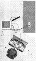
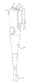
図4Aは、本開示の実施の形態に従う、典型的な輸送内視鏡300の略図であり、図4B-4Dは、輸送内視鏡300に挿入されるか又はそこから引き抜かれうる代表的な可撓性のある細長いアセンブリの図である。可撓性のある細長いアセンブリは、図4B-4Cに示されるような作動アセンブリ400a,400bと図4Dに示されたような可撓性のある撮像内視鏡アセンブリ450からなることもある。
作動アセンブリ400a,400bは、本開示の実施の形態に従い、たとえば、図4Bに示されるような把持器400a又は図4Cに示されるような焼灼器であるロボット手術器具であるか又はそれらを含むこともある。可撓性のある撮像内視鏡アセンブリ450は、本開示の実施の形態に従い、図4Dに示されるような撮像内視鏡プローブであることもある。図4Aに関し、輸送内視鏡300は、近端に本体310と、遠端に可撓性のある細長いシャフト320を含む。好適な実施の形態において、本体310は、硬質プラスティック又は金属のような硬質材料製であり得るとともに、可撓性のある細長いシャフト320はゴムやゴム状、及び/又は軟プラスティック材料のような可撓性材料製である。
4A is a schematic illustration of an
Actuating assemblies 400a, 400b are or include a robotic surgical instrument that is, for example, a gripper 400a as shown in FIG. 4B or a cautery as shown in FIG. 4C, in accordance with an embodiment of the present disclosure. There is also. The flexible
本体310は、輸送内視鏡300の近位部分、縁部、表面もしくは端部を含むか又は画定するとともに、それを通って、可撓性のある細長いシャフト320の内部及びそれに沿って延びるチャンネルがアクセス可能である複数の挿入インレット315を提供する。本体310は、近端部又は近端311aと遠端部又は遠端311bと近端311aと遠端311bの間に延在する若しくは近端311aから遠端311bに延在するハウジング312を含む。ハウジング312は、複数の表面と複数の挿入インレットを含む。複数の挿入インレット315は、本体310の近端311aに設けられており、たとえば、本体の近端311aにおいて複数の挿入インレット315がハウジング312の少なくとも一つの面(たとえば、本体の近端311aにおいてハウジング312の頂面又は頂面のセット)に存在するように設けられている。
The
いくつかの実施の形態では、本体310はさらに、輸送内視鏡300用の制御インタフェースを提供し、それにより、内視鏡医は、可撓性のある細長いシャフト320に対しナビゲーション制御を加えることができる。たとえば、本体310は、多数の制御要素、たとえば、一以上のボタン、ノブ、スイッチ、レバー、ジョイスティック及び/又は他の制御要素を含み、関連技術における当業者により容易に理解される態様にて、輸送内視鏡の作動に対する内視鏡医の制御を容易にする。
In some embodiments, the
可撓性のある細長いシャフト320は、本体310の遠端311bから離れて、輸送内視鏡300の遠位端部で終端するように構成されている。可撓性のある細長いシャフト320は、近端321aと遠端321bと(図示しない)中心軸と可撓性のある細長いアセンブリの部分を保持するためのその内部の複数のチャンネルと複数のチャンネルのそれぞれのために可撓性のある細長いシャフトの遠端321bに設けられた開口を含む。
The flexible
複数のチャンネルは、図4B〜4Cに示すような作動アセンブリ400a,400bを保持する器具チャンネルのセットを含むことが出来る。様々な実施の形態では、可撓性のある細長いシャフト320の遠端が存在する環境に、通気もしくは陽圧、吸気もしくは吸引圧及び、洗浄液の送出を可能にするための通路をさらに含むことがある。
The plurality of channels can include a set of instrument channels that hold actuation assemblies 400a, 400b as shown in FIGS. In various embodiments, the environment in which the distal end of the flexible
各作動アセンブリ400a,bは、概して所定のタイプの内視鏡ツールに対応している。例えば、代表的な実施においては、第1の作動アセンブリ400aは図4Bに示すようなエンドエフェクタ420aの把持器若しくは同タイプの器具を有する第1のロボットアーム410aを搭載することが出来る。そして、第2の作動アセンブリ400bは図4Cに示すような焼灼エンドエフェクタ420bの焼灼スパチュラ若しくは同タイプの器具を有する第2のロボットアーム410bを搭載することが出来る。 Each actuation assembly 400a, b generally corresponds to a predetermined type of endoscopic tool. For example, in a typical implementation, the first actuation assembly 400a may carry a first robot arm 410a having a gripper or similar type of instrument of an end effector 420a as shown in FIG. 4B. The second actuating assembly 400b can be mounted with a second robot arm 410b having a cautery spatula of the ablation end effector 420b as shown in FIG. 4C or an instrument of the same type.
図4B〜4Cに示す実施の形態では、所定の作動アセンブリ400a,bは、ロボットアーム410a,b及びそれに対応するエンドエフェクタ420a,bと、ロボットアーム410a、b及び/又はエンドエフェクタ420a、bの作動を正確に操作及び制御するための特定の緊張材要素に張力もしくは機械力が選択的に加えられ得るように、内部で複数の緊張材/シース要素を保持する可撓性のある細長いアウタスリーブ及び/又はコイル402a、bと、下記に詳述するように、アウタスリーブ402a、b内の緊張材をモータボックス600内で、対応する作動器に機械的に連結させることのできる器具入力アダプタ710a、bとを含む。代表的なタイプの緊張材/シース要素、ロボットアーム410a,b、エンドエフェクタ420a,b、そして、緊張材要素がロボットアーム410a,bの部分(たとえば、ジョイント/ジョイントプリミティブ)及び対応するエンドエフェクタ420a,bに連結して制御し、有効なDOFに対し操縦性/操作性を提供する代表的な方法が、(a)国際特許出願第PCT/SG2013/000408号と、(b)国際公開第WO2010/138083号に詳述されている。所定の緊張材とそれに対応するシースは、緊張材/シース要素として、画定されうる。
In the embodiment shown in FIGS. 4B-4C, a given actuation assembly 400a, b includes robot arms 410a, b and corresponding end effectors 420a, b and robot arms 410a, b and / or end effectors 420a, b. A flexible elongated outer sleeve that holds a plurality of tendon / sheath elements therein so that tension or mechanical force can be selectively applied to a particular tendon element for precise manipulation and control of actuation And / or
図4Bと4Cにおいて、ロボットアーム410a、b、エンドエフェクタ420a、b及び、アウタスリーブ/コイル402a、bの部分は、可撓性のある細長いシャフト320の器具チャンネル内へ挿入されることができ、ロボットアーム410a、b及びエンドエフェクタ420a、bは、可撓性のある細長いシャフト320の遠端321bに到達し又はほぼ到達し、更に、それを越えて所定の距離で延びることができる。以下に詳説するように、作動アセンブリのアウタスリーブ/コイル402a、bと、それによるロボットアーム410a、b及びエンドエフェクタ420a、bは選択的に、移動ユニットにより、長手方向に移動され又はサージされる(可撓性のある細長いシャフト320の遠端321bに対して遠位側もしくは近位側に変位される)ことができ、それにより、可撓性のある細長いシャフト320の遠端321bに対するロボットアーム410a、b及びエンドエフェクタ420a、bの近端−遠端の部分は、内視鏡処置を実行するため、可撓性のある細長いシャフト320の遠端321bを越える予め決められた最大の距離まで、可撓性のある細長いシャフト320の遠位端部321bを越えた環境内で調整することができる。多くの実施の形態において、作動アセンブリ400は、配設可能である。
4B and 4C, portions of the robot arm 410a, b, end effector 420a, b and outer sleeve /
特定の実施の形態では、作動アセンブリ400a、bは、エンドエフェクタ420a、bの遠先端から離れた所定の距離で、アウタスリーブ/コイル402a、bの少なくとも一部を囲繞するカラー要素、コレットもしくはバンド430a、bを含む。以下に詳説するように、カラー要素430a、bは、移動機構の受容部(receiver)と嵌合し係合するよう設計され、それにより、可撓性のある細長いシャフト320の遠端に対する所定の距離を越えるカラー要素430a、bの長手方向/サージ移動が、ロボットアーム410a、b及びエンドエフェクタ420a、bの対応する長手方向/サージ移動をもたらす。
In certain embodiments, the actuation assembly 400a, b includes a collar element, collet or band surrounding at least a portion of the outer sleeve /
いくつかの実施の形態では、可撓性のある細長いシャフト320内に設けられる複数のチャンネルは、さらに、輸送内視鏡300内に挿入されるとともにそれから引き抜かれることのできる、図4Dに示すような可撓性のある撮像内視鏡アセンブリ450の部分を保持するよう構成される撮像内視鏡チャンネルを含む。図4に関連して、作動アセンブリ400a、bについて上述したものと類似する又はほぼ類似する態様においては、実施の形態では、撮像内視鏡アセンブリ450は、可撓性のある撮像内視鏡460の外面を囲繞する又はそれを形成する可撓性のあるアウタスリーブ、コイルもしくはシャフト452と、可撓性のある細長いシャフト320の遠端321bにおいて、その近傍で及び/又はそれを越える環境内で、一以上のDOF(たとえば上下動及び/又は揺動運動)に従って選択的に操作され又は位置決めされることができるように、撮像内視鏡460に対応する又はその内部の緊張材のセットを、モータボックス600内で対応する作動器に機械的に連結させることのできる撮像入力アダプタ750と、撮像内視鏡460の光学的要素(たとえば光ファイバー)を撮像サブシステム210の画像処理装置に光学的に連結させることのできる撮像コネクタアセンブリ470とを含む。たとえば、撮像内視鏡460は、緊張材を含み又はそれに連結されることができ、それにより、撮像内視鏡460の遠端又は面が、内視鏡処置の間に、ロボットアーム410a、b及びエンドエフェクタ420a、bの順行及び逆行画像を選択的に/選択可能に捉えることができる。本開示の実施の形態に従い、撮像内視鏡アセンブリ450に組み入れることができ、それと協働する緊張材のような撮像内視鏡及び制御要素の代表的な実施の形態が、国際特許出願第PCT/SG2013/000408号に詳述されている。ある実施の形態においては、撮像内視鏡アセンブリ450が配設されうる。
In some embodiments, the plurality of channels provided in the flexible
作動アセンブリ400a、b用のものと同一の、本質的に同一の又は類似の態様で、撮像内視鏡アセンブリ450のアウタスリーブ452及び、それによる撮像内視鏡460の遠端は、移動機構により、可撓性のある細長いシャフト320の遠端321bに対して選択的に長手方向移動/サージされることができ、それにより、撮像内視鏡460の長手方向もしくは近端−遠端の位置は、内視鏡処置に関連する予め決められた近端−遠端の距離範囲を越える可撓性のある細長いシャフト320の遠端において、その近傍に及び/又はそれを越えて調整されることができる。
In the same, essentially the same or similar manner as for the actuation assemblies 400a, b, the
多くの実施の形態では、撮像内視鏡アセンブリ450は、撮像内視鏡450の遠端460から離れた所定の距離で、撮像内視鏡アセンブリのアウタスリーブ452の少なくとも部分を囲繞するカラー要素430cを含む。カラー要素430cは、移動機構の受容部又は受容構造と嵌合し係合するように構成され、それにより、可撓性のある細長いシャフト320の遠端に対する所定の距離を越えるカラー要素430cの長手方向/サージ変位は、撮像内視鏡460の遠端の対応する長手方向/サージ変位をもたらす。
In many embodiments, the
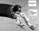
結果的に、いくつかの実施の形態において、図5に示すように、輸送内視鏡300は、本開示の実施の形態に従い、輸送内視鏡の遠端を越えた環境に位置する、二個のロボットアーム410a,bとそれに搭載された対応エンドエフェクタ420a,bと、更に、可撓性のある撮像内視鏡を有することが出来る。
As a result, in some embodiments, as shown in FIG. 5, the
ある実施の形態においては、作動アセンブリ400a、400bと可撓性のある撮像内視鏡アセンブリ450からなる可撓性のある細長いアセンブリは、可撓性のある細長いアセンブリの軸は可撓性のある細長いシャフト320の中心軸と平行した状態で、挿入インレットを介して可撓性のある細長いシャフト320内の複数のチャンネルに挿入可能である。言い換えれば、図4Bと4Cの作動アセンブリ400a、bと図4Dの可撓性のある撮像内視鏡アセンブリ450は、それぞれ、関連技術における当業者により容易に理解される態様で、作動アセンブリ400a、bの軸と可撓性のある撮像内視鏡アセンブリの軸が図9Aに示すように可撓性のある細長いシャフト320の中心軸と平行した状態で、若しくは、可撓性のある細長いシャフト320によって保持された器具チャンネル又は撮像内視鏡チャンネルに平行した状態で、輸送内視鏡300の器具チャンネル及び撮像内視鏡チャンネル内へ挿入されるとともにそれから引き抜かれるよう構成される。それに応じて、若しくは、それに相当して、挿入インレット315のそれぞれは、作動アセンブリ400又は可撓性のある撮像内視鏡アセンブリ450が挿入可能なそれに対応した挿入軸を有して、可撓性のある細長いシャフト320の近端又はその近傍において、挿入インレット315の挿入軸が可撓性のある細長いシャフト320の中心軸と平行になるようにすることが出来る。所定の挿入インレット315について、作動アセンブリ400又は可撓性のある撮像内視鏡アセンブリ450が挿入された/挿入可能である挿入インレットのアパーチュア又は開口の面がその挿入軸を横切るか又は直角である。
In one embodiment, a flexible elongate assembly comprising actuation assemblies 400a, 400b and a flexible
更に、図4B〜4Cに関して、内視鏡処置中に可撓性のある細長いシャフト320の遠端を越える環境で、作動アセンブリ400a、bと可撓性のある撮像内視鏡アセンブリ450が、それらの操作に先立ち、輸送内視鏡300に十分に挿入されたとき、各カラー要素430a−cは、可撓性のある細長いシャフト320の外側にであって、そこから少なくとも若干離間したままであるか、様々な実施の形態においては、輸送内視鏡の本体310の外側にであって、そこから少なくとも若干離間したままであり、予め決められた近端―遠端の距離に亘る所定のカラー要素430a−cの長手方向の移動又はサージ運動は、可撓性のある細長いシャフト320及び/又は本体310からの干渉なしに、移動ユニットにより自由に生じ得る。したがって、カラー要素430a、bが移動ユニットに対して最も近い位置に存在するときに、エンドエフェクタ420a、bが、可撓性のある細長いシャフト320の遠端321bに到達し又はほぼ到達するように、各作動アセンブリ400a、bのアウタスリーブ/コイル402a、bは、そのカラー要素430a、bの遠位縁部から十分に離れた長さで遠くに延びる必要がある。同様に、カラー要素430cが移動ユニットに対して最も近い位置にあるときに、撮像内視鏡460の遠端部が、可撓性のある細長いシャフト320の遠端321bでの、その近傍の又はその近くの意図された位置に存在するように、撮像内視鏡アセンブリのアウタスリーブ452は、そのカラー要素430cから十分に離れた長さで遠くに延びる必要がある。
Further, with respect to FIGS. 4B-4C, in an environment beyond the distal end of the flexible
図4Aに戻り、輸送内視鏡300は、別途、関連技術における当業者により容易に理解される態様で、それにより輸送内視鏡本体が内視鏡サポート機能サブシステム250と連結される内視鏡サポート機能コネクタアセンブリ370を含むことが出来る。
Returning to FIG. 4A, the
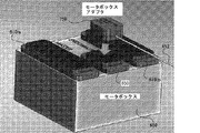
図6は、本開示の実施の形態に従う、典型的な本体310をより詳細に図示している。図6に示すように、本体310は、近端311aに延びるハウジング312と、ハウジング312の表面上のジョイント部材316と遠端311bに向かうグリップ313を含むことがある。また、本体310は、更に、本体310と可撓性のある細長いシャフト320を接続するコネクタ314を含むこともある。より緻密若しくは好適な実施の形態においては、ハウジング312は、立方体又はほぼ立体形状(たとえば、長方形若しくはほぼ長方形の立体チューブ)であるか若しくはそれを含んでおり、複数の挿入インレット315は、ハウジング312の近端に向かいその上面及び/又は頂面に形成されるようにしてもよい。また、ジョイント部材は、輸送内視鏡300をスレーブシステム200の他の要素、例えば後述するドッキングステーション500に嵌合し、ハウジングの側面に装備されることもある。グリップ313は、臨床医(例えば、内視鏡医又は外科医)が握って輸送内視鏡300をスレーブシステムの他の要素と連結又は噛み合わせ、スレーブシステムの他の要素及び/又は被験者又は患者に対し輸送内視鏡300の部分を空間的に調整、位置決め、移動する領域、部分、又は構造を提供する。
FIG. 6 illustrates an
本開示の実施の形態に従い、ジョイント部材316は、近端311aから遠端311bに延在するハウジング312の側面に配置され、グリップ313は輸送内視鏡300の遠端に向かって配置される。すなわち、ジョイント部材316は、輸送内視鏡300の近端に向かって配置され、グリップ313は本体310の輸送内視鏡300の遠端に向かって配置される。したがって、臨床医が、輸送内視鏡300とドッキングステーション500又は図11〜14に示されるようなドッキング機構を噛み合わせたりそれから解きはなったりするために、本体のグリップを変えたり放す必要はない。
According to the embodiment of the present disclosure, the
実施の形態の詳細により、本体310の表面上の挿入インレット315は、様々に配設されうる。より緻密若しくは好適な実施の形態においては、臨床医が可撓性のある細長いアセンブリを輸送内視鏡300又はスレーブ又はスレーブサイドのシステム200に挿入/そこから取り出すときに、輸送内視鏡300と、作動アセンブリ400a、400bと可撓性のある撮像内視鏡アセンブリ450を含む可撓性のある細長いシャフト320の双方に対する機械的ストレスを減少又は最小にするように、挿入インレットは配置されることがある。ある実施の形態においては、図7A〜7Bに示すように、直線的又はほぼ直線的な態様で(直線によって)配置されうる。また、挿入インレット315は、図7Aに示すように、表面の所定の境界線、縁、端、側線に平行な一線に配設されうるか、または、図7Bに示すように対角線上に配設されうる。挿入インレットの数は、図7Cに示すように、輸送内視鏡300に挿入されるべき可撓性のある内視鏡アセンブリの数に従い、変更可能であり、その配置は適宜変更されうる。
Depending on the details of the embodiment, the
輸送内視鏡300の典型的な実施の形態が、国際特許出願第PCT/SG2013/000408に詳述されている。決められた実施の形態において、輸送内視鏡300は、他の数の作動センブリ400を保持するように構成することもできる。更に、輸送内視鏡300、その内部のチャンネル/通路、一以上の作動アセンブリ400及び/又は撮像内視鏡アセンブリ450の断面寸法は、考慮中の所定の種の外科/内視鏡処置及び/又は輸送内視鏡シャフトサイズ/寸法束縛に従い、決定されうる。
An exemplary embodiment of a
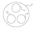
図8Aは、本開示の他の実施の形態に従う可撓性のある細長いシャフト320の典型的な略断面図であり、ここでは、その内部のチャンネル/通路は、高い/最大のDOFロボットアーム/エンドエフェクタ410、420に適合するように構成された大きな又は最大の断面積/径を有するプライマリ器具チャンネル330と、たとえば従来の把持具のような手動操作型の従来の内視鏡器具/ツールに適合するように構成されて、プライマリ器具チャンネル330より小さな又は著しく小さな断面積/径を有するセコンダリ器具チャンネル360と(たとえば、そのような実施の形態では、ロボット作動アセンブリ400及び従来の/手動の作動アセンブリは、輸送内視鏡本体310内の対応するポート内に挿入されることができる)、撮像内視鏡460に適合するように構成された撮像内視鏡チャンネル335を含む。
FIG. 8A is an exemplary schematic cross-sectional view of a flexible
代わりの実施の形態において、図8Aに示されたそれのような可撓性のある細長いシャフト320は、撮像内視鏡460に適合するように構成された撮像内視鏡チャンネル335を排除又は削除することがあり、そして、むしろ撮像内視鏡460の部分とは分離され、その部分に搭載されていない、又はその部分を形成しない従来の内視鏡撮像要素又はデバイスであって、(例えば、撮像内視鏡チャンネル335により)可撓性のある細長いシャフト320に挿入可能でありそこから取り出し可能である従来の内視鏡撮像要素又はデバイスを含むか又は搭載することもある。但し、この従来の内視鏡撮像要素又はデバイスは、可撓性のある細長いシャフトの遠端321bを越えた環境での画像(たとえば、内視鏡処置中に、ロボットエンドエフェクタ420及び/又は手動操作エンドエフェクタの一以上の画像)の捕捉を容易又は可能にするように構成されている。実施の形態の詳細により、そのような従来の内視鏡撮像要素は、光源又は光デバイス(例えば、LED)及び/又はそれに対応する光ファイバのセットと、撮像デバイス(例えば、CCDチップ及び/又は他のタイプの撮像センサ)と、レンズ(その少なくともあるものは、例えば、関連技術における当業者により容易に理解される態様で、可撓性のある細長いシャフト320内に組み込まれているか、若しくは、そこに固定されている結果、可撓性のある細長いシャフト320に対して位置的に固定されている)。たとえば、このような実施の形態において、レンズは、可撓性のある細長いシャフト320の遠端321b(たとえば、その垂直又は傾斜した面に)に搭載又は配設若しくは取り付けられ得るとともに、撮像センサがレンズの背後に配拙されうる。
In an alternative embodiment, a flexible
図8Bは、本開示のさらに他の実施の形態に従う可撓性のある細長いシャフト320の典型的な略断面図であり、ここでは、その内部のチャンネル/通路は、図8Aの可撓性のある細長いシャフトと比較して、低減/制限されたDOFロボットアーム/エンドエフェクタ410a、b、420a、bに適合するように構成された相対的に(より)小さな断面積もしくは径を有する第一及び第二器具チャンネル332a、bと、撮像内視鏡460に適合するように構成された撮像内視鏡チャンネル335とを含む。
FIG. 8B is an exemplary schematic cross-sectional view of a flexible
図8A及び8Bに示すそれらのような可撓性のある細長いシャフトの実施の形態は、関連技術における当業者により容易に理解される態様で、所定のタイプの内視鏡処置を容易にし、及び/又は、挿管を改善させる目的で、ここでの他の箇所で述べる可撓性のある細長いシャフト320より小さな全断面積をもたらすことができる。
Embodiments of flexible elongate shafts such as those shown in FIGS. 8A and 8B facilitate certain types of endoscopic procedures in a manner readily understood by those skilled in the relevant art, and For the purpose of improving intubation, an overall cross-sectional area can be provided that is smaller than the flexible
<典型的な処理セットアップとモータボックスへ連結するインタフェース>
図9A〜9Cは、撮像内視鏡アセンブリ450及び一対の作動アセンブリ400a、bを、輸送内視鏡300内に挿入するとともに、モータボックス600を含むスレーブシステム200の他の部分に連結し又はインタフェースすることのできるようにする典型的なセットアップ処置の部分を図示する。
<Typical processing setup and interface to motor box>
FIGS. 9A-9C connect the
図9Aに示すように、カラー要素430cより遠位側でそれに対応する撮像内視鏡アセンブリのアウタスリーブ452の部分は、輸送内視鏡の本体310内に形成された挿入インレット315のうちの一つ内に挿入されることができ、それにより、撮像内視鏡460は、シャフト320に沿って、その遠端321bに対して当初意図された、デフォルトの又は停止される位置に送られるとともに遠位側に前進させられ得る。先に述べたように、撮像内視鏡アセンブリのアウタスリーブ452に連結されたカラー要素430cは、可撓性のある細長いシャフト320の外側にある状態が維持される。より具体的には、図示の実施の形態では、カラー要素430cが撮像内視鏡アセンブリ450のアウタスリーブ452が受容されるポートの近くで所定の距離に存在するように、カラー要素430cは、輸送内視鏡の本体310の外側にある状態が維持される。画像コネクタアセンブリ470は、たとえば、図9Aに示す態様で、関連技術における当業者により容易に理解されるように、撮像サブシステム210に連結されることができ、それにより、撮像内視鏡460は、照明を出力するとともに、画像を捉えることができる。
As shown in FIG. 9A, the portion of the
図9Bにさらに示すように、撮像内視鏡アセンブリの画像入力アダプタ750は、モータボックス600の対応する画像出力アダプタ650に連結されることができる。そのようなアダプタとアダプタとの連結により、撮像内視鏡アセンブリのアウタスリーブ452の内部の緊張材のセットは、モータボックス600内で、一以上の作動器又はモーターに機械的に連結もしくは結合され得る。そのような緊張材は、例えば、国際特許出願第PCT/SG2013/000408号に記載された態様で、一以上のDOFに従って、撮像内視鏡460を位置決め若しくは操作するよう構成される。それ故に、撮像内視鏡位置制御に関連するモータボックス600内の一以上の作動器による撮像内視鏡アセンブリの緊張材への選択的な張力の適用の結果として、撮像内視鏡460は、可撓性のある細長いシャフト320の遠端321bに対して特定の態様で選択的に位置決めもしくは操作されうる。
As further shown in FIG. 9B, the
前述したところに加えて、関連技術における当業者により容易に理解される態様にて、通気もしくは陽圧、吸気もしくは陰圧/真空圧及び、洗浄の供給を容易にするため、輸送内視鏡のサポート機能コネクタアセンブリ370は、たとえば、図9Cに示す態様で、内視鏡サポート機能サブシステム270に連結されうる。 In addition to the foregoing, in a manner readily understood by those skilled in the relevant art, in order to facilitate the supply of ventilation or positive pressure, suction or negative / vacuum pressure, and cleaning, The support function connector assembly 370 may be coupled to the endoscope support function subsystem 270, for example, in the manner shown in FIG. 9C.
図10A〜10Cは、輸送内視鏡300と撮像内視鏡アセンブリ450と一対の作動アセンブリ400a、bがドッキングステーション500と移動ユニット510と噛合して係合されるドッキング機構を図示している。図10Aを参照すると、輸送内視鏡の本体310は、ドッキングステーション500にドッキングされ又は取り付けられることができ、また、撮像内視鏡アセンブリのカラー要素430cは、ドッキングステーション500に関連する移動ユニット510により与えられる対応する受容部もしくはクリップ530c内に挿入されるか、又は、それと噛合し係合されることができる。一旦撮像内視鏡アセンブリのカラー要素430cが、対応するクリップ530cに確実に保持されると、さらに詳細を以下に述べるように、たとえば、マスタステーション100でのハプティップ入力デバイス110a、b又は他の制御装置(たとえばフットペダル)の外科医操作、及び/又は、輸送内視鏡の本体310上の制御要素の内視鏡医操作に応じて(たとえば、ここでは、撮像内視鏡460を長手方向に移動/サージすることに関して内視鏡医入力より外科医入力を優先させることができる)、撮像内視鏡アセンブリのスリーブ452は、所定の近端−遠端の距離範囲にを越えて移動ユニット510により、選択的に/選択可能に長手方向に移動もしくはサージされることができる。
10A to 10C illustrate a docking mechanism in which the
図10Bを参照すると、図10Aにおいて上述したところと類似の態様にて、対応する作動アセンブリカラー要素430a、bより遠くの各作動アセンブリ400a、bの部分は、輸送内視鏡300の本体310内で、意図された/適切な寸法のポート内に挿入されることができる。その結果として、各ロボットアーム410a、b及びエンドエフェクタ420a、bは、可撓性のある細長いシャフト内に送られるとともに、可撓性のある細長いシャフト320に沿って遠くに、可撓性のある細長いシャフトの遠端321bに対して当初意図された、デフォルトの又は停止される位置に向けて、その位置へ前進させられ得る。各作動アセンブリのアウタスリーブ/コイル402a、bにより保持されるカラー要素430a、bは、可撓性のある細長いシャフト320の外側、いくつかの実施の形態では輸送内視鏡の本体310の外側にある状態が維持され、それにより、各カラー要素430a、bは、作動アセンブリ400a、bのアウタスリーブ/コイル402a、bが受容されるポートより近くの所定の距離に存在する。
Referring to FIG. 10B, in a manner similar to that described above in FIG. 10A, the portion of each actuation assembly 400a, b that is further than the corresponding actuation assembly collar element 430a, b is within the
撮像内視鏡アセンブリ450用のものに類似する態様では、各作動アセンブリのカラー要素430a、bは、移動ユニット510により与えられる対応する受容部もしくはクリップ530a、b内に挿入されるとともに、それと噛合し係合されることができる。一旦そのような各カラー要素430a、bが、その対応するクリップ530a、bにより確実に保持されると、移動ユニット510は、たとえば、マスタステーション100でのハプティップ入力デバイス110a、bの一方又は両方の外科医操作に応じて、所定の近端−遠端の距離範囲を越えて作動アセンブリ400a、bの一方又は両方を(たとえば独立した態様で)、選択的に/選択可能に長手方向に移動させ又はサージさせることができる。
In a manner similar to that for the
図10Cは、ドッキングステーション500に関連する又はそれに搭載される典型的な移動ユニット510と、作動アセンブリ400a、b及び撮像内視鏡アセンブリ450に対応するカラー要素430a〜cが、対応する移動ユニットクリップ530a〜cにより保持される典型的な態様を示す略図である。移動ユニット510は、各作動アセンブリ400a、b及び撮像内視鏡アセンブリ450に対応する独立して調整可能な/移動可能な移動ステージを含むことができる。典型的な実施においては、所定の移動ステージは、関連技術における当業者により容易に理解される態様にて、所定の最大距離範囲に亘って対応のクリップ530に、長手方向/サージ変位を与えるように構成されたリニア作動器もしくはボールねじとし、又はそれを含むことができる。
FIG. 10C shows a typical moving
図11A〜11Cは、本開示の実施の形態に従う、輸送内視鏡300がドッキングステーション500に嵌合して係合するドッキング機構を図示している。図11A〜11Cに関し、ジョイント部材540は、ドッキングステーション500の表面上に形成される。ジョイント部材540は、突起部541と、突起部541の側面に形成された複数のバンプ542と、ロックレバー543からなる。図11Aに示すように、内視鏡医は、矢示551aの方向に輸送内視鏡の本体310とジョイント部材540を整列させ嵌合する。そしてその後に、図11Bに示すように、内視鏡医が、矢示551bの方向に、ロックレバー543を回転すると、輸送内視鏡の本体310がドッキングステーションのジョイント部材540と連結される。また、内視鏡医は、ロッキングレバー543を矢示551cの方向に回転して矢示551dの方向に輸送内視鏡300を開放することで、輸送内視鏡300をリリースすることが出来る。
11A-11C illustrate a docking mechanism in which the
図12は、図11A〜11Cのドッキング機構をより詳細に示す。図12に示すように、輸送内視鏡のジョイント部材340は、ドッキングステーションのジョイント部材540を収納するための溝342と、ドッキングステーション500のジョイント部材のバンプ542と嵌合して係合されるスロット344a〜344dを有する。図11A〜12又は図10Aに関連して記載された実施の形態においては、輸送内視鏡300は、少なくとも一つの可撓性のある細長いものが移動ユニット510に嵌合し係合されたと同じ方法からドッキングステーション500に嵌合される。
FIG. 12 shows the docking mechanism of FIGS. 11A-11C in more detail. As shown in FIG. 12, the
図13A〜13Cは、本開示の他の実施の形態に従う、輸送内視鏡300がドッキングステーション500に嵌合して係合するドッキング機構を図示している。図13A〜13Cに関し、ドッキングステーション500のジョイント部材550は、輸送内視鏡の本体310が挿入されるスロット551と、押すと、ジョイント部材550と輸送内視鏡の本体310の嵌合をリリースする一対のリリースボタン552からなる。図13A〜13Bに示すように、内視鏡医は、矢示553aの方向に本体310をスロット551内に摺動することで、本体310とドッキングステーションのジョイント部材540を整列させ嵌合する。リリースボタン552のセットが矢示553bの方向に作動したときに、本体310は、関連技術における当業者により容易に理解される態様にて、ドッキングステーション500からリリースされうる。
13A-13C illustrate a docking mechanism in which the
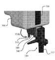
図14は、本開示の実施の形態に従う、図13A〜3Cのドッキング機構のための輸送内視鏡の本体310の図である。図14に示すように、輸送内視鏡の本体310のジョイント部材350は、(図示しない)ドッキングステーション500内のジョイント部材550の対応する内側スロット551を収納することのできるクランプ部材355を含む。図13A〜14に関連して記載された実施の形態において、たとえば、可撓性のある細長いシャフトの近端321aで、輸送内視鏡が可撓性のある細長いシャフト320の中心軸に平行な方向からドッキングステーションと嵌合される。
14 is a diagram of a
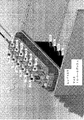
図15は、本開示の実施の形態に従う、各作動アセンブリの器具入力アダプタ710a、bの、モータボックス600の対応する器具出力アダプタ610a、bへの連結を示す略図である。そのようなアダプタとアダプタの連結により、各作動アセンブリのアウタスリーブ/コイル402a、bの内部の緊張材は、モータボックス600内で、特定の作動器又はモーターに機械的に連結され又は結合されうる。いづれかの所定の作動アセンブリ400でも、そのような緊張材は、例えば、(a)国際特許出願第PCT/SG2013/000408号及び/又は国際公開公報第WO2010/138083号に記載された態様で、所定のDOFに従い、ロボットアーム410a、b及び対応するエンドエフェクタ420a、bを位置決め又は操作するように構成される。それ故に、各作動アセンブリのロボットアーム410a、b及びエンドエフェクタ402a、bは、ロボットアーム/エンドエフェクタ位置制御に関連するモータボックス600内での一以上の作動器/モーターによる作動アセンブリ400a、b内の緊張材への張力の選択的な適用の結果として、可撓性のある細長いシャフト320の遠端321bに対して選択的に位置決め又は操作されることができる。さらに、そのようなアダプタとアダプタの連結は、内視鏡処置の開始に先立って、各作動アセンブリ400a、b内の緊張材における意図された、所望の又は所定の張力レベルの設定、再設定又は検証を可能にし(たとえば緊張材プリテンションレベル)、またいくつかの実施の形態では、内視鏡処置の間に、緊張材張力レベルの調整またはオンザフライ設定を可能にする。また、様々な実施の形態では、以下にさらなる詳述するように、器具入力アダプタ710a、bが、器具出力アダプタ610a、bと噛合しておらず、又は、それから解除されるとき、そのようなアダプタとアダプタの連結は、作動器センブリ緊張材内で、規定の又は所定の張力レベル(たとえば所定の最小張力レベル)の維持を可能にする。
FIG. 15 is a schematic diagram illustrating the coupling of instrument input adapters 710a, b of each actuation assembly to corresponding instrument output adapters 610a, b of
<典型的な入力アダプタ及び出力アダプタ構造及び連結>
図16は、本開示の実施の形態に従う、モータボックス600の器具出力アダプタ610に取り付けられる作動アセンブリの器具入力アダプタ710の典型的な内側部分を示す欠載斜視図である。図17は、本開示の実施の形態に従う、互いに連結され又は噛合し係合されたときの器具出力アダプタ610及び器具アダプタ710の典型的な内側部分を示す対応する断面図である。図18A〜18Dは、本開示の実施の形態に従う、器具出力アダプタ610との器具入力アダプタ710の噛合及び、それからの器具入力アダプタ710の解除の様々な段階に対応する、器具入力アダプタ710により提供される作動噛合構造720の典型的な内側部分及び、その内部の要素の部分を示す断面図である。
<Typical input adapter and output adapter structure and connection>
FIG. 16 is a cutaway perspective view showing a typical inner portion of the instrument input adapter 710 of the actuation assembly attached to the instrument output adapter 610 of the
図16を参照すると、実施の形態では、器具入力アダプタ710は、複数の作動係合構造720、たとえば、器具入力アダプタ710が関連する特定の作動アセンブリ400のロボットアーム/エンドエフェクタ410、420を制御するように構成された各モータボックス・作動器/モーター620に対する個々の作動噛合構造720を含む。
Referring to FIG. 16, in an embodiment, instrument input adapter 710 controls a plurality of
所定の実施の形態では、モータボックス600は、ロボットアーム/エンドエフェクタ410、420の各DOFを制御するための単一の作動器/モーターを含むが、この場合、器具入力アダプタ710は、そのような各DOFに対応する単一の作動噛合構造720を含む。そのような実施の形態では、どのDOFも、(特定のそのシース内に存在する)単一の緊張材に対応する。
In certain embodiments, the
様々な実施の形態では、モータボックス600は、作動アセンブリのロボットアーム/エンドエフェクタ410、420により提供される各DOFを制御するための二重又は対をなす作動器/モーター620を含む。そのような実施の形態では、どの所定のDOFも、一対の緊張材(たとえば、第一シース内に存在する第一緊張材及び、第二シース内に存在する第二緊張材)に対応する。この場合、モータボックス600内の二個の作動器/モーターは互いに同期して作動され、それにより、所定の一対の緊張材(たとえば第一緊張材及び第二緊張材)が、ロボットアーム/エンドエフェクタ410、420の所定のDOFを制御する。
In various embodiments, the
結果として、器具入力アダプタ710はそれに応じて、各ロボットアーム/エンドエフェクタDOFに対応する一対の作動噛合構造720を含む。ロボットアーム/エンドエフェクタ410、420が六つのDOFに関して位置決め可能/操作可能である典型的な実施においては、モータボックス600は、このロボットアーム/エンドエフェクタ410、420を制御するための12個の作動器/モーター600a〜lを含み、更に、器具入力アダプタ710は、12個の作動噛合構造720a〜lを含む。器具入力アダプタ710はモータボックス600に取り付け、それにより、特定のロボットアーム/エンドエフェクタDOFに関してロボットアーム/エンドエフェクタの操作可能/配置可能を与えるため、特定の対の作動噛合構造720(たとえば、器具入力アダプタ710の長さに沿って互いに隣り合う態様で配置される作動噛合構造720)が、モータボックス600内で作動器/モーター620a〜lの片方の対に対応するとともに、それに機械的に連結される。
As a result, instrument input adapter 710 accordingly includes a pair of
図17、また図18A〜18Dに示すように、実施の形態では、作動係合構造720は、(a)フレーム部材722の上側境界を画定するフレーム部材プラットフォーム724を支持する複数のアーム部材723を有するフレーム部材722であって、前記フレーム部材プラットフォーム724が、そのようなアーム部材723と垂直又は直角であるフレーム部材722と、(b)フレーム部材のプラットフォーム724の中心もしくは中央領域を通って上側に延出するとともに、モータボックス出力アダプタ610のアウタディスク626に向かって下側に延出し、それにより噛合することのできる細長い入力シャフト726であって、長手方向(たとえば、その長さと平行な垂直方向)の軸に沿って移動可能な細長い入力シャフト726と、(c)入力シャフト726に取り付けられてその周囲に周方向に配設されるドラム構造730であって、(i)上面、外面及び底面を有するテーパードラム732及び、(ii)ドラム732の底面から離れて所定の距離で、入力シャフト726と垂直又は直角に保持される第一ラチェット要素734を含むドラム構造730と、(d)フレーム部材のプラットフォーム724の下側とドラム732の上面との間で、入力シャフト726の周囲に周方向に配設される弾性付勢要素もしくはスプリング728と、(e)入力シャフト726と垂直又は直角で、その周囲に周方向に配設されるとともに、フレーム部材のプラットフォーム724の下側から離れて所定の距離で、第一ラチェット要素734の下側に配設される第二ラチェット要素744とを含む。様々な実施の形態では、第二ラチェット要素744は、入力シャフト726に対して位置固定され、不動であり又は移動できない。
As shown in FIG. 17 and FIGS. 18A-18D, in an embodiment, the
ドラム構造は、ドラム732の底面と第一ラチェット要素734の上面との間の空間的間隔を画定するカラー部分733を含む。緊張材の近端は、ドラム構造730の一部(たとえば、第一ラチェット要素734の上面上に保持された圧着固定具/アバットメント)に連結され、結合され又は固定されることができ、更に、緊張材は、ドラム構造のカラー部分733の周囲の周りに強固に巻き付けられることができ、それにより、カラー部分733は、その周りに複数もしくは多数の緊張材の巻回部を保持する。その反対/遠端に向く方向で、カラー部分722の周りに巻き付けられた緊張材は、エンドエフェクタ420、又は、作動アセンブリのロボットアーム410上の所定の位置(たとえば、ロボットアームジョイント又はジョイント要素に対する特定の位置)に到達するまで、作動アセンブリのアウタスリーブ/コイル402の長さに向かって、その内部に且つそれに沿って、ドラム構造730から離れて延びることができる。
The drum structure includes a
ドラム構造730の回転又は、それに対応した入力シャフト726の回転は、ドラム構造730が回転する方向に従って、ドラム構造のカラー部分733の周りでの緊張材の更なる巻き付き、又は、カラー部分733からの緊張材の部分的な巻き戻しをもたらす。関連技術における当業者により容易に理解される態様で、カラー部分733の周りでの緊張材の巻き付きは、緊張材の張力の増大をもたらすとともに、作動アセンブリのアウタスリーブ/コイル402内に存在する緊張材の長さを低減させることができ、また、カラー部分733からの緊張材の巻き戻しは、緊張材の張力の減少をもたらすとともに、作動アセンブリのアウタスリーブ/コイル402内に存在する緊張材の長さを増大させることができる。それ故に、選択的な緊張材の巻き付き/巻き戻しは、特定のDOFに対して、ロボットアーム/エンドエフェクタ410、420の正確な操作/位置決めを容易にするか又は可能にする。
The rotation of the
より具体的には、各DOF用のデュアルモーター制御をもたらす実施の形態では、片方のドラム構造730の同期回転による、特定のDOFに対応する対をなす緊張材の巻き付き/巻き戻しの同期は、このDOFに従い、ロボットアーム/エンドエフェクタ410、420の操作/位置決めをもたらす。そのような同期ドラム構造回転は、更に以下に詳述するように、作動噛合構造入力シャフト726が回転可能に連結される一対の作動器/モーター620及び対応する出力ディスク626により選択的に/選択可能に生じ得る。
More specifically, in an embodiment that provides dual motor control for each DOF, the synchronization of the wrapping / unwinding of a pair of tendons corresponding to a particular DOF by synchronous rotation of one
器具入力アダプタ710が、モータボックス600の器具出力アダプタ610と噛合されない又は解除されたとき、作動噛合構造のスプリング728は、第一又はデフォルト位置に、作動噛合構造のドラム構造730を下向きに付勢又は押圧し、それにより、第一ラチェット要素734は、第二ラチェット要素744と強固に噛合し係合される。スプリング728がドラム構造730を下向きに付勢するときの、第二ラチェット要素744との第一ラチェット要素734のそのような噛合は、図18Aに示されている。第一及び第二ラチェット要素734、744のそのような噛合の結果として、ドラム構造730は回転が防止され、それにより、ドラム構造730に対応する緊張材内での張力が維持され又は保存される(緊張材内の張力は変化することができない又は十分に変化することができない)。
When the instrument input adapter 710 is not mated or released with the instrument output adapter 610 of the
上述したように、作動噛合構造の入力シャフト726は、その長手方向の軸と平行に又はそれに沿って移動可能である。器具入力アダプタ710が、(たとえば、一以上のスナップフィット結合により)モータボックス600の器具出力アダプタ610上に取り付けられ又は設置されるので、第二ラチェット要素744の下側で入力シャフト726により保持される下側プレート728の底面は、特定の作動器/モーター620に関連する出力ディスク628の上面により保持される突起部のセットに接触する。それ故に、スプリング728は圧縮されるとともに、それにより保持される入力シャフト726及びドラム構造730は上側に移動されて、図18Bに示すように、ドラム732の上面とフレーム部材のプラットフォーム724との間の距離が減少する。ドラム構造730のそのような上側の移動は、第一ラチェット要素734が、第二ラチェット要素744から解除されることを引き起こす。これは、器具入力アダプタ710が、モータボックス600の器具出力アダプタ上に配設され又は取り付けられるが、入力シャフト726がまだ、作動器/モーター620の出力ディスク626と回転して、回転可能に/回転して連結されていない状況に対応するものとすることができる。
As described above, the input shaft 726 of the actuating mesh structure is movable parallel to or along its longitudinal axis. Since the instrument input adapter 710 is mounted or installed on the instrument output adapter 610 of the motor box 600 (eg, by one or more snap-fit couplings), it is held by the input shaft 726 below the
モータボックス600の器具出力アダプタ610への器具入力アダプタ710の取り付けの間、又は、一旦器具入力アダプタ710が、(たとえば、センサのセットにより検出できるように)器具出力アダプタ610上に十分に/強固に取り付けられると、入力シャフト726及びドラム構造730が垂直に上側に移動するとともに、第一及び第二ラチェット要素が互いに係合解除されるようになった状況に対応して、モータボックス600内の作動器/モーター620は、(たとえば制御ユニット800の指示の下で)初期化プロセスを開始する。初期化プロセスの間、出力ディスク628により保持される突起部のセットが、入力シャフトの下側プレート728の底面内で、片方の凹部を受け止め又はそれと噛合し係合するまで、各作動器/モーター620は、その対応する出力ディスク628を回転する。
During attachment of the instrument input adapter 710 to the instrument output adapter 610 of the
一旦出力ディスク628により保持された突起部が、入力シャフトの下側プレート728内に形成された片方の凹部を受け止め又はそれと噛合し係合すると、入力シャフト726は、図18Cに示す態様で、意図された作動器/モーター620に回転して連結される。そのような出力ディスク突起部及び下側プレート凹部が回転して連結されるとき、作動器/モーター620は、ドラム構造730のカラー部分733の周りの緊張材の巻き付き及び巻き戻しを選択的に正確に制御し、及び/又は、緊張材張力を正確に制御することができ、それにより、マスタステーション100で受信される外科医入力に応じて、意図された態様で、ロボットアーム/エンドエフェクタ410、420を操作/位置決めを行う。
Once the protrusion retained by the
器具入力アダプタ710が、器具出力アダプタ610から解除され、取り外され又は分離されるとき、スプリング728の緊張からの開放は、ドラム構造730の上面を下向きに押圧し、それにより、第一ラチェット要素734は、図18Dに示す態様で、第二ラチェット要素744と噛合い係合される。入力シャフト726及びディスク構造730の回転はその後阻止され、それにより、緊張材張力は、図18Aに関連して上述したものと本質的に同様に又は類似の態様で維持される。
When the instrument input adapter 710 is released from the instrument output adapter 610, removed or disconnected, the release from the tension of the
本開示の特定の実施の形態の側面は、既存の可撓性のあるマスタースレーブ視鏡ロボットシステム及びデバイスに関する少なくとも一つの側面、問題、制限及び/又は不都合を解決している。特定の実施の形態に関する特徴、側面及び/又は利点を本開示において説明したが、他の実施の形態もまた、そのような特徴、側面及び/又は利点を呈することがあり、そして、全ての実施の形態が、本開示の範囲内に含まれるために、そのような特徴、側面及び/又は利点を呈することは必ずしも必要ではない。先に開示したシステム、コンポーネント、プロセス又はその代替手段のいくつかは、他の異なるシステム、コンポーネント、プロセス及び/又は適用内に望ましく組み合せられ得ることが当業者には理解される。また、様々な変更、修正及び/又は改作が、本開示の範囲内で、当業者によって開示される様々な実施の形態においてなされ得る。 Aspects of certain embodiments of the present disclosure address at least one aspect, problem, limitation, and / or disadvantage of existing flexible master-slave endoscopic robot systems and devices. While features, aspects and / or advantages relating to particular embodiments have been described in this disclosure, other embodiments may also exhibit such features, aspects and / or advantages, and all implementations Are not necessarily required to exhibit such features, aspects and / or advantages in order to fall within the scope of this disclosure. Those skilled in the art will appreciate that some of the systems, components, processes or alternatives disclosed above may be desirably combined within other different systems, components, processes and / or applications. In addition, various changes, modifications, and / or adaptations may be made in various embodiments disclosed by those skilled in the art within the scope of the present disclosure.
Claims (14)
本体と、中心軸と前記少なくとも一つの可撓性のある細長いアセンブリの部分を保持するための内部の複数のチャンネルを含む可撓性のある細長いシャフトを有する輸送内視鏡と、
該輸送内視鏡と着脱自在に嵌合するように構成されたドッキングステーションであって、前記少なくとも一つの可撓性のある細長いアセンブリに嵌合して係合すると共に、前記少なくとも一つの可撓性のある細長いアセンブリを予め決められた距離範囲を越えて長手方向に選択的に移動するように構成された移動ユニットを有する前記ドッキングステーションと、
前記少なくとも一つの可撓性のある細長いアセンブリのそれぞれを駆動するように構成された複数の作動器を含むモータボックスと、
外部制御信号に従って前記複数の作動器のそれぞれを制御するように構成された主制御ユニットと、
前記輸送内視鏡に配設されたジョイント部材と前記ドッキングステーションに配設された対応するジョイント部材からなるドッキング機構と、
該ジョイント部材と対応するジョイント部材を係合するロック機構と、からなるロボット内視鏡システムであって、
前記ドッキング機構が、輸送内視鏡を、(a)少なくとも一つの可撓性のある細長いアセンブリが移動ユニットと噛合して係合するのと同じ方向、及び、(b)可撓性のある細長いシャフトの中心軸に平行な方向のうちの何れか一つの方向から前記ドッキングステーションに嵌合可能にするように配置されているロボット内視鏡システム。 At least one flexible elongate assembly configured to perform an endoscopic procedure in response to a force generated by an external actuation element;
A body, a transport endoscope having an elongate shaft flexibility of including a plurality of channels of interior for holding a central axis portion of said at least one flexible elongate assembly,
A docking station that is configured to freely fit removably with the transport endoscope, wherein with engagement fitted to the elongate assembly with at least one flexible, said at least one flexible Said docking station having a moving unit configured to selectively move a longitudinal elongated assembly over a predetermined distance range in a longitudinal direction;
A motor box including a plurality of actuators configured to drive each of the at least one flexible elongate assembly;
A main control unit configured to control each of the plurality of actuators according to an external control signal;
A docking mechanism comprising a joint member disposed in the transport endoscope and a corresponding joint member disposed in the docking station;
A robot endoscope system comprising: a lock mechanism that engages a joint member corresponding to the joint member,
The docking mechanism includes a transport endoscope, (a) in the same direction that at least one flexible elongate assembly is engaged and engaged with the moving unit; and (b) a flexible elongate assembly. any one disposed to have endoscope system robot so as to be fitted from the direction to the docking station of the direction parallel to the central axis of the shaft.
ロボットアームと、外部作動要素によって発生された力に従って内視鏡処置を行うように構成された対応するエンドエフェクタと、
前記外部作動要素によって発生された力を前記ロボットアームとエンドエフェクタに伝えるように構成された複数の緊張材要素と、
該複数の緊張材要素と外部作動要素を連結するように構成されたアダプタからなる作動アセンブリである請求項1に記載のロボット内視鏡システム。 At least one flexible elongated assembly is
A robot arm and a corresponding end effector configured to perform an endoscopic procedure according to the force generated by the external actuation element;
A plurality of tendon elements configured to transmit the force generated by the external actuation element to the robot arm and an end effector;
The robot endoscope system according to claim 1, wherein the robot endoscope system is an actuating assembly comprising an adapter configured to connect the plurality of tendon elements and an external actuating element.
エンドエフェクタの画像を取り込むように構成された撮像ユニットと、
加えられた力に応じて撮像ユニットを空間的な位置決めをするように構成された複数の緊張材要素と、
それによって該複数の緊張材要素が特定の外部作動要素に連動されるアダプタからなる可撓性のある撮像内視鏡アセンブリである請求項1に記載のロボット内視鏡システム。 One of the elongate assembly with the flexible,
An imaging unit configured to capture an image of the end-effector,
A plurality of tendon elements configured to spatially position the imaging unit in response to the applied force;
The robotic endoscope system according to claim 1, wherein the plurality of tendon elements are flexible imaging endoscope assemblies comprising adapters that are linked to specific external actuating elements.
Priority Applications (1)
| Application Number | Priority Date | Filing Date | Title |
|---|---|---|---|
| JP2019181567A JP6894647B2 (en) | 2015-03-19 | 2019-10-01 | Flexible extended robot endoscopy device |
Applications Claiming Priority (1)
| Application Number | Priority Date | Filing Date | Title |
|---|---|---|---|
| PCT/SG2015/050042 WO2016148642A1 (en) | 2015-03-19 | 2015-03-19 | An enhanced flexible robotic endoscopy apparatus |
Related Child Applications (1)
| Application Number | Title | Priority Date | Filing Date |
|---|---|---|---|
| JP2019181567A Division JP6894647B2 (en) | 2015-03-19 | 2019-10-01 | Flexible extended robot endoscopy device |
Publications (3)
| Publication Number | Publication Date |
|---|---|
| JP2018509267A JP2018509267A (en) | 2018-04-05 |
| JP2018509267A5 JP2018509267A5 (en) | 2018-05-24 |
| JP6606797B2 true JP6606797B2 (en) | 2019-11-20 |
Family
ID=56920346
Family Applications (1)
| Application Number | Title | Priority Date | Filing Date |
|---|---|---|---|
| JP2018500265A Active JP6606797B2 (en) | 2015-03-19 | 2015-03-19 | Robot endoscope system |
Country Status (5)
| Country | Link |
|---|---|
| US (3) | US10939804B2 (en) |
| JP (1) | JP6606797B2 (en) |
| CN (2) | CN111528766A (en) |
| SG (1) | SG11201707729QA (en) |
| WO (1) | WO2016148642A1 (en) |
Families Citing this family (11)
| Publication number | Priority date | Publication date | Assignee | Title |
|---|---|---|---|---|
| TWI795414B (en) | 2017-06-29 | 2023-03-11 | 美商美國德州系統大學評議委員會 | Surgical apparatus and surgical instrument thereof |
| US11369399B2 (en) * | 2017-07-14 | 2022-06-28 | Actuated Medical, Inc. | Device for aiding in the positioning and anchoring of an endoscope during gastrointestinal procedures |
| WO2019070201A1 (en) | 2017-10-06 | 2019-04-11 | Endomaster Pte Ltd | An endoscope system |
| AU2020261742B2 (en) * | 2019-04-23 | 2023-01-19 | Boston Scientific Scimed, Inc. | Modular scope device |
| CN114126470A (en) | 2019-05-17 | 2022-03-01 | 波士顿科学国际有限公司 | System and apparatus for a tubeless working channel for an endoscope |
| JP7329428B2 (en) | 2019-12-04 | 2023-08-18 | Hoya株式会社 | endoscope device |
| US20230056943A1 (en) * | 2019-12-13 | 2023-02-23 | Dinesh Vyas | Stapler apparatus and methods for use |
| USD1022197S1 (en) | 2020-11-19 | 2024-04-09 | Auris Health, Inc. | Endoscope |
| WO2022201110A1 (en) * | 2021-03-25 | 2022-09-29 | Pitale Ashok Rahul Kumar | Telescopic flexible tendon continuum endoscope and method of operation thereof |
| KR102378015B1 (en) * | 2021-05-28 | 2022-03-24 | 주식회사 엔도로보틱스 | Tendon-sheath driving apparatus and robot arm driving apparatus |
| CN115919475B (en) * | 2023-03-10 | 2023-05-23 | 北京云力境安科技有限公司 | Split type soft type endoscopic surgery robot system |
Family Cites Families (28)
| Publication number | Priority date | Publication date | Assignee | Title |
|---|---|---|---|---|
| JPS6240567Y2 (en) * | 1980-05-02 | 1987-10-17 | ||
| US5025778A (en) * | 1990-03-26 | 1991-06-25 | Opielab, Inc. | Endoscope with potential channels and method of using the same |
| US5197457A (en) * | 1990-09-12 | 1993-03-30 | Adair Edwin Lloyd | Deformable and removable sheath for optical catheter |
| US5259366A (en) * | 1992-11-03 | 1993-11-09 | Boris Reydel | Method of using a catheter-sleeve assembly for an endoscope |
| JP3679440B2 (en) * | 1995-02-22 | 2005-08-03 | オリンパス株式会社 | Medical manipulator |
| US6419626B1 (en) * | 1998-08-12 | 2002-07-16 | Inbae Yoon | Surgical instrument endoscope with CMOS image sensor and physical parameter sensor |
| US7819799B2 (en) * | 2000-03-16 | 2010-10-26 | Immersion Medical, Inc. | System and method for controlling force applied to and manipulation of medical instruments |
| JP4451123B2 (en) * | 2003-11-27 | 2010-04-14 | オリンパス株式会社 | Endoscope |
| EP4026486A1 (en) * | 2004-03-23 | 2022-07-13 | Boston Scientific Medical Device Limited | In-vivo visualization system |
| EP1818005B1 (en) | 2004-12-03 | 2017-03-01 | Olympus Corporation | Power driven bending endoscope with detachable insertion portion |
| US20060252993A1 (en) * | 2005-03-23 | 2006-11-09 | Freed David I | Medical devices and systems |
| JP4728075B2 (en) * | 2005-09-28 | 2011-07-20 | オリンパスメディカルシステムズ株式会社 | Endoscope system |
| US7918783B2 (en) * | 2006-03-22 | 2011-04-05 | Boston Scientific Scimed, Inc. | Endoscope working channel with multiple functionality |
| CN104688281B (en) | 2006-06-13 | 2017-04-19 | 直观外科手术操作公司 | Minimally invasive surgical system |
| US8986197B2 (en) | 2007-02-20 | 2015-03-24 | Olympus Medical Systems Corp. | Medical system and endoscope system |
| US8591399B2 (en) | 2007-04-25 | 2013-11-26 | Karl Storz Endovision, Inc. | Surgical method utilizing transluminal endoscope and instruments |
| US8529554B2 (en) * | 2007-09-05 | 2013-09-10 | Olympus Medical Systems Corp. | Treatment instrument operation unit and medical system with treatment instrument operation unit |
| US8343034B2 (en) * | 2008-05-13 | 2013-01-01 | Olympus Medical Systems Corp. | Electric medical instrument fitting which is attached to a medical instrument holding device |
| WO2010055745A1 (en) * | 2008-11-14 | 2010-05-20 | オリンパスメディカルシステムズ株式会社 | Medical system |
| WO2010138083A1 (en) | 2009-05-29 | 2010-12-02 | Nanyang Technological University | Robotic system for flexible endoscopy |
| US9877744B2 (en) * | 2010-02-12 | 2018-01-30 | Intuitive Surgical Operations, Inc. | Entry guide for multiple instruments in a single port surgical system |
| US9345859B2 (en) * | 2012-09-06 | 2016-05-24 | Corindus, Inc. | Hemostasis valve and system for guide catheter control |
| CN104883991B (en) * | 2012-09-19 | 2018-08-28 | 南洋理工大学 | Flexible master-slave mode robotic endoscope checks system |
| JP6251756B2 (en) | 2013-02-26 | 2017-12-20 | アーメット・シナン・カバクチュAhmet Sinan KABAKCI | Robot manipulator system |
| JP6023872B2 (en) * | 2013-03-29 | 2016-11-09 | 富士フイルム株式会社 | Endoscopic surgery device |
| JP2014226374A (en) * | 2013-05-23 | 2014-12-08 | オリンパス株式会社 | Endoscope distal end structure and endoscope |
| JP6027947B2 (en) * | 2013-07-26 | 2016-11-16 | オリンパス株式会社 | Manipulator system |
| CN106455934A (en) * | 2015-01-16 | 2017-02-22 | 奥林巴斯株式会社 | Over tube and manipulator system |
-
2015
- 2015-03-19 CN CN202010460686.8A patent/CN111528766A/en active Pending
- 2015-03-19 WO PCT/SG2015/050042 patent/WO2016148642A1/en active Application Filing
- 2015-03-19 CN CN201580079889.XA patent/CN107613832B/en not_active Expired - Fee Related
- 2015-03-19 JP JP2018500265A patent/JP6606797B2/en active Active
- 2015-03-19 US US15/127,398 patent/US10939804B2/en active Active
- 2015-03-19 SG SG11201707729QA patent/SG11201707729QA/en unknown
-
2020
- 2020-06-24 US US16/911,348 patent/US11696673B2/en active Active
-
2021
- 2021-03-05 US US17/194,183 patent/US20210186309A1/en not_active Abandoned
Also Published As
| Publication number | Publication date |
|---|---|
| US20210007583A1 (en) | 2021-01-14 |
| JP2018509267A (en) | 2018-04-05 |
| WO2016148642A1 (en) | 2016-09-22 |
| CN111528766A (en) | 2020-08-14 |
| CN107613832A (en) | 2018-01-19 |
| US11696673B2 (en) | 2023-07-11 |
| US20210186309A1 (en) | 2021-06-24 |
| SG11201707729QA (en) | 2017-10-30 |
| US20170332882A1 (en) | 2017-11-23 |
| US10939804B2 (en) | 2021-03-09 |
| CN107613832B (en) | 2020-07-28 |
Similar Documents
| Publication | Publication Date | Title |
|---|---|---|
| JP6606797B2 (en) | Robot endoscope system | |
| US20200315720A1 (en) | Flexible robotic endoscopy system | |
| JP2020072935A (en) | Tendon control robotic arm | |
| KR102569960B1 (en) | Instrument device manipulator for a surgical robotics system | |
| JP2017515615A5 (en) | ||
| CN103561667A (en) | Grip force control in a robotic surgical instrument | |
| JP6894647B2 (en) | Flexible extended robot endoscopy device | |
| US20230329816A1 (en) | Endoscopic devices, systems and methods | |
| EP3082563B1 (en) | An enhanced flexible robotic endoscopy apparatus | |
| Oleynikov et al. | SURGICAL CAMERA ROBOT: United States Patent NO. US 7,339,341 B2 |
Legal Events
| Date | Code | Title | Description |
|---|---|---|---|
| A521 | Request for written amendment filed |
Free format text: JAPANESE INTERMEDIATE CODE: A523 Effective date: 20180130 |
|
| A521 | Request for written amendment filed |
Free format text: JAPANESE INTERMEDIATE CODE: A523 Effective date: 20180126 |
|
| A521 | Request for written amendment filed |
Free format text: JAPANESE INTERMEDIATE CODE: A523 Effective date: 20180319 |
|
| A621 | Written request for application examination |
Free format text: JAPANESE INTERMEDIATE CODE: A621 Effective date: 20180319 |
|
| A977 | Report on retrieval |
Free format text: JAPANESE INTERMEDIATE CODE: A971007 Effective date: 20181227 |
|
| A131 | Notification of reasons for refusal |
Free format text: JAPANESE INTERMEDIATE CODE: A131 Effective date: 20190115 |
|
| A601 | Written request for extension of time |
Free format text: JAPANESE INTERMEDIATE CODE: A601 Effective date: 20190411 |
|
| A521 | Request for written amendment filed |
Free format text: JAPANESE INTERMEDIATE CODE: A523 Effective date: 20190614 |
|
| TRDD | Decision of grant or rejection written | ||
| A01 | Written decision to grant a patent or to grant a registration (utility model) |
Free format text: JAPANESE INTERMEDIATE CODE: A01 Effective date: 20190903 |
|
| A711 | Notification of change in applicant |
Free format text: JAPANESE INTERMEDIATE CODE: A711 Effective date: 20191003 |
|
| A61 | First payment of annual fees (during grant procedure) |
Free format text: JAPANESE INTERMEDIATE CODE: A61 Effective date: 20191003 |
|
| A521 | Request for written amendment filed |
Free format text: JAPANESE INTERMEDIATE CODE: A821 Effective date: 20191003 |
|
| R150 | Certificate of patent or registration of utility model |
Ref document number: 6606797 Country of ref document: JP Free format text: JAPANESE INTERMEDIATE CODE: R150 |
|
| R250 | Receipt of annual fees |
Free format text: JAPANESE INTERMEDIATE CODE: R250 |