JP6605616B2 - Techniques for managing power operating modes of user equipment (UE) communicating using multiple radio access technologies (RAT) - Google Patents
Techniques for managing power operating modes of user equipment (UE) communicating using multiple radio access technologies (RAT) Download PDFInfo
- Publication number
- JP6605616B2 JP6605616B2 JP2017548844A JP2017548844A JP6605616B2 JP 6605616 B2 JP6605616 B2 JP 6605616B2 JP 2017548844 A JP2017548844 A JP 2017548844A JP 2017548844 A JP2017548844 A JP 2017548844A JP 6605616 B2 JP6605616 B2 JP 6605616B2
- Authority
- JP
- Japan
- Prior art keywords
- connection
- power
- mode
- reordering
- receiving
- Prior art date
- Legal status (The legal status is an assumption and is not a legal conclusion. Google has not performed a legal analysis and makes no representation as to the accuracy of the status listed.)
- Expired - Fee Related
Links
Images


Classifications
-
- H—ELECTRICITY
- H04—ELECTRIC COMMUNICATION TECHNIQUE
- H04W—WIRELESS COMMUNICATION NETWORKS
- H04W28/00—Network traffic management; Network resource management
- H04W28/02—Traffic management, e.g. flow control or congestion control
- H04W28/0215—Traffic management, e.g. flow control or congestion control based on user or device properties, e.g. MTC-capable devices
- H04W28/0221—Traffic management, e.g. flow control or congestion control based on user or device properties, e.g. MTC-capable devices power availability or consumption
-
- H—ELECTRICITY
- H04—ELECTRIC COMMUNICATION TECHNIQUE
- H04W—WIRELESS COMMUNICATION NETWORKS
- H04W52/00—Power management, e.g. TPC [Transmission Power Control], power saving or power classes
- H04W52/02—Power saving arrangements
- H04W52/0209—Power saving arrangements in terminal devices
- H04W52/0212—Power saving arrangements in terminal devices managed by the network, e.g. network or access point is master and terminal is slave
- H04W52/0216—Power saving arrangements in terminal devices managed by the network, e.g. network or access point is master and terminal is slave using a pre-established activity schedule, e.g. traffic indication frame
-
- H—ELECTRICITY
- H04—ELECTRIC COMMUNICATION TECHNIQUE
- H04W—WIRELESS COMMUNICATION NETWORKS
- H04W52/00—Power management, e.g. TPC [Transmission Power Control], power saving or power classes
- H04W52/02—Power saving arrangements
- H04W52/0209—Power saving arrangements in terminal devices
- H04W52/0225—Power saving arrangements in terminal devices using monitoring of external events, e.g. the presence of a signal
- H04W52/0229—Power saving arrangements in terminal devices using monitoring of external events, e.g. the presence of a signal where the received signal is a wanted signal
-
- H—ELECTRICITY
- H04—ELECTRIC COMMUNICATION TECHNIQUE
- H04W—WIRELESS COMMUNICATION NETWORKS
- H04W52/00—Power management, e.g. TPC [Transmission Power Control], power saving or power classes
- H04W52/02—Power saving arrangements
- H04W52/0209—Power saving arrangements in terminal devices
- H04W52/0251—Power saving arrangements in terminal devices using monitoring of local events, e.g. events related to user activity
- H04W52/0258—Power saving arrangements in terminal devices using monitoring of local events, e.g. events related to user activity controlling an operation mode according to history or models of usage information, e.g. activity schedule or time of day
-
- H—ELECTRICITY
- H04—ELECTRIC COMMUNICATION TECHNIQUE
- H04W—WIRELESS COMMUNICATION NETWORKS
- H04W76/00—Connection management
- H04W76/10—Connection setup
- H04W76/15—Setup of multiple wireless link connections
- H04W76/16—Involving different core network technologies, e.g. a packet-switched [PS] bearer in combination with a circuit-switched [CS] bearer
-
- H—ELECTRICITY
- H04—ELECTRIC COMMUNICATION TECHNIQUE
- H04W—WIRELESS COMMUNICATION NETWORKS
- H04W76/00—Connection management
- H04W76/20—Manipulation of established connections
- H04W76/28—Discontinuous transmission [DTX]; Discontinuous reception [DRX]
-
- Y—GENERAL TAGGING OF NEW TECHNOLOGICAL DEVELOPMENTS; GENERAL TAGGING OF CROSS-SECTIONAL TECHNOLOGIES SPANNING OVER SEVERAL SECTIONS OF THE IPC; TECHNICAL SUBJECTS COVERED BY FORMER USPC CROSS-REFERENCE ART COLLECTIONS [XRACs] AND DIGESTS
- Y02—TECHNOLOGIES OR APPLICATIONS FOR MITIGATION OR ADAPTATION AGAINST CLIMATE CHANGE
- Y02D—CLIMATE CHANGE MITIGATION TECHNOLOGIES IN INFORMATION AND COMMUNICATION TECHNOLOGIES [ICT], I.E. INFORMATION AND COMMUNICATION TECHNOLOGIES AIMING AT THE REDUCTION OF THEIR OWN ENERGY USE
- Y02D30/00—Reducing energy consumption in communication networks
- Y02D30/70—Reducing energy consumption in communication networks in wireless communication networks
Description
米国特許法第119条に基づく優先権の主張
[0001]本特許出願は、両方の出願が本出願の譲受人に譲渡され、両方の出願全体が参照により本明細書に明確に組み込まれる、2015年3月19日に出願された「TECHNIQUES FOR MANAGING POWER OPERATION MODES OF A USER EQUIPMENT (UE) COMMUNICATING WITH A PLURALITY OF RADIO ACCESS TECHNOLOGIES (RATS)」と題する仮出願番号第62/135,583号、および2016年3月10日に出願された「TECHNIQUES FOR MANAGING POWER OPERATION MODES OF A USER EQUIPMENT (UE) COMMUNICATING WITH A PLURALITY OF RADIO ACCESS TECHNOLOGIES (RATS)」と題する米国特許出願番号第15/066,214号の優先権を主張する。
Claiming priority under 35 USC 119
[0001] This patent application is a "TECHNIQUES FOR" filed on March 19, 2015, both of which are assigned to the assignee of this application and both applications are expressly incorporated herein by reference. MANAGING POWER OPERATION MODES OF A USER EQUIMENT (UE) COMMUNICATING WITH A PURALITY OF RADIO ACCESS TECHNOLOGIES (RATES) MANAGING POWER OPERATION MODES OF A USER EQUIIPMENT (UE) COMMUNICATING WITH A PLULARITY O Claims priority of US patent application Ser. No. 15 / 066,214 entitled “F RADIO ACCESS TECHNOLOGIES (RATES)”.
[0002]本開示は、たとえば、ワイヤレス通信システムに関し、より詳細には、複数の無線アクセス技術(RAT)を用いて通信するユーザ機器(UE)の電力動作モードを管理するための技法に関する。 [0002] The present disclosure relates to wireless communication systems, for example, and more particularly to techniques for managing power operating modes of user equipment (UE) that communicate using multiple radio access technologies (RATs).
[0003]ワイヤレス通信ネットワークは、音声、ビデオ、パケットデータ、メッセージング、ブロードキャストなどの様々な通信サービスを提供するために広く展開されている。これらのワイヤレスネットワークは、利用可能なネットワークリソースを共有することによって複数のユーザをサポートすることが可能な多元接続ネットワークであり得る。そのような多元接続ネットワークの例としては、符号分割多元接続(CDMA)ネットワーク、時分割多元接続(TDMA)ネットワーク、周波数分割多元接続(FDMA)ネットワーク、直交FDMA(OFDMA)ネットワーク、およびシングルキャリアFDMA(SC−FDMA)ネットワークがある。 [0003] Wireless communication networks are widely deployed to provide various communication services such as voice, video, packet data, messaging, broadcast, and so on. These wireless networks may be multiple access networks that can support multiple users by sharing available network resources. Examples of such multiple access networks include code division multiple access (CDMA) networks, time division multiple access (TDMA) networks, frequency division multiple access (FDMA) networks, orthogonal FDMA (OFDMA) networks, and single carrier FDMA ( SC-FDMA) network.
[0004]ワイヤレス通信ネットワークは、いくつかのユーザ機器(UE)のための通信をサポートすることができるいくつかの基地局(たとえば、eノードB)を含み得る。UEは、ダウンリンクとアップリンクとを介して基地局と通信し得る。ダウンリンク(または順方向リンク)は基地局からUEへの通信リンクを指し、アップリンク(または逆方向リンク)はUEから基地局への通信リンクを指す。 [0004] A wireless communication network may include a number of base stations (eg, eNode Bs) that can support communication for a number of user equipments (UEs). The UE may communicate with the base station via the downlink and uplink. The downlink (or forward link) refers to the communication link from the base station to the UE, and the uplink (or reverse link) refers to the communication link from the UE to the base station.
[0005]さらに、UEは、802.11(Wi−Fi(登録商標))などのワイヤレス通信技術を使用して1つまたは複数のホットスポットにアクセスすることによってワイヤレスローカルエリアネットワーク(WLAN)において通信する能力があり得る。この点について、UEは、1つまたは複数のWLANの無線アクセスネットワーク(RAN)とともにワイヤレスワイドエリアネットワーク(WWAN)のRAN(たとえば、セルラーネットワーク)と通信することができる。UEは、WWANのRANと通信するように動作可能な受信機(たとえば、ロングタームエボリューション(LTE(登録商標))、ユニバーサル電気通信モバイルシステム(UMTS)、または同様の受信機)とWLANのRANと通信するように動作可能な別の受信機(たとえば、802.11 Wi−Fi受信機)とを含むことができる。UEは、追加または代替として、両方のRAN(たとえば、WWANおよびWLAN)と通信するために動作可能な単一の受信機を含み得る。いずれの場合も、WWANおよびWLANを介した通信は、1つまたは複数のネットワークノードへの同時アクセスを与えること、WWANからWLANにまたはその逆にトラフィックをオフロードすることなどを行うために、(たとえば、メディアアクセス制御(MAC)、パケットデータコンバージェンスプロトコル(PDCP)または同様のレイヤにおいて)アグリゲートされ得、これは、「RANアグリゲーション」サッチと呼ばれることがある。 [0005] Further, the UE communicates in a wireless local area network (WLAN) by accessing one or more hotspots using a wireless communication technology such as 802.11 (Wi-Fi®). There may be the ability to In this regard, a UE may communicate with a wireless wide area network (WWAN) RAN (eg, a cellular network) along with one or more WLAN radio access networks (RANs). The UE can be configured to communicate with a WWAN RAN (eg, Long Term Evolution (LTE), Universal Telecommunications Mobile System (UMTS), or similar receiver) and a WLAN RAN. And another receiver operable to communicate (eg, an 802.11 Wi-Fi receiver). The UE may additionally or alternatively include a single receiver operable to communicate with both RANs (eg, WWAN and WLAN). In any case, communication over WWAN and WLAN can be used to provide simultaneous access to one or more network nodes, offload traffic from WWAN to WLAN, or vice versa ( For example, it may be aggregated (at Media Access Control (MAC), Packet Data Convergence Protocol (PDCP) or similar layer), which may be referred to as a “RAN Aggregation” thatch.
[0006]RANアグリゲーションの現在の実装形態では、WWANアクセスポイントは、所与のUEについてWWAN接続とWLAN接続とを介したダウンリンク通信をスケジュールし、UEは、WWAN接続を介してWWAN RANと、WLAN接続を介してWLAN RANと通信する。WLANアクセスポイントは、次いで、UEとWWANアクセスポイントとの間で、WWANによってスケジュールされたデータを通信し得る。したがって、ダウンリンク上で、WWAN接続とWLAN接続とからのデータパケットは、分割され、UEにおいて順序が乱れて受信され得、したがって、UEは、独立したWWAN接続とWLAN接続とを介して受信されたデータパケットに関連するシーケンス番号に基づいてMACレイヤ、RLCレイヤまたはPDCPレイヤにおいて順が狂ったパケットを並べ替えることができる。しかしながら、UEは、電力消費量を節約すること、(たとえば、より良い無線条件をもつアクセスポイントの位置を特定するために)他のチャネルを走査することなどを行うために接続のうちの1つまたは複数を介してある電力動作モード(たとえば、アイドルモード)に入り得る。この例では、UEは、受信されたデータパケットの並べ替えを適切に実行するために接続のうちの1つまたは複数を介してデータパケットを受信するために異なる電力動作モード(たとえば、接続モード)に切り替わるために十分な時間を有しないことがある。したがって、UEは、データパケットを再送するように要求し得、これは、ワイヤレスネットワークのリソースを不要に浪費することをもたらし得る。 [0006] In the current implementation of RAN aggregation, a WWAN access point schedules downlink communication over a WWAN connection and a WLAN connection for a given UE, and the UE communicates with the WWAN RAN over the WWAN connection; Communicate with WLAN RAN via WLAN connection. The WLAN access point may then communicate data scheduled by the WWAN between the UE and the WWAN access point. Thus, on the downlink, data packets from WWAN and WLAN connections may be split and received out of order at the UE, so the UE is received via independent WWAN and WLAN connections. Packets out of order in the MAC layer, RLC layer, or PDCP layer can be rearranged based on the sequence numbers associated with the data packets. However, the UE can use one of the connections to save power consumption, scan other channels (eg, to locate an access point with better radio conditions), etc. Or, a power operating mode (eg, idle mode) may be entered via a plurality. In this example, the UE has different power operating modes (eg, connection modes) to receive data packets over one or more of the connections in order to properly perform the reordering of received data packets. You may not have enough time to switch to Thus, the UE may request to retransmit the data packet, which may result in unnecessarily wasting wireless network resources.
[0007]以下で、1つまたは複数の態様の基本的理解を与えるために、そのような態様の簡略化された概要を提示する。この概要は、すべての考えられる態様の包括的な概説ではなく、すべての態様の主要または重要な要素を識別することも、いずれかまたはすべての態様の範囲を定めることも意図していない。その唯一の目的は、後に提示されるより詳細な説明の導入として、1つまたは複数の態様のいくつかの概念を簡略化された形で提示することである。 [0007] The following presents a simplified summary of such aspects in order to provide a basic understanding of one or more aspects. This summary is not an extensive overview of all possible aspects and is not intended to identify key or critical elements of all aspects or to delineate the scope of any or all aspects. Its sole purpose is to present some concepts of one or more aspects in a simplified form as a prelude to the more detailed description that is presented later.
[0008]本開示は、たとえば、概して、ワイヤレス通信システムに関し、より詳細には、複数の無線アクセス技術(RAT)を用いて通信するユーザ機器(UE)の電力動作モードを管理するための技法に関する。たとえば、異なる無線アクセス技術(RAT)の1つまたは複数の接続が電力消費量を節約するための電力動作モードにある、無線アクセスネットワーク(RAN)中のワイヤレスデバイス、基地局、および/またはアクセスポイントとの間の通信を管理するための技法について、本明細書で説明する。 [0008] The present disclosure relates generally to wireless communication systems, and more particularly to techniques for managing power operating modes of user equipment (UE) that communicate using multiple radio access technologies (RATs). . For example, wireless devices, base stations, and / or access points in a radio access network (RAN) where one or more connections of different radio access technologies (RAT) are in a power mode of operation to conserve power consumption Techniques for managing communication with are described herein.
[0009]一態様によれば、ワイヤレスデバイス(たとえば、ユーザ機器(UE))は、異なる無線アクセス技術(RAT)および/またはネットワークアーキテクチャを使用して、複数のRAN中のアクセスポイントと通信し得る。たとえば、ワイヤレスデバイスは、1つまたは複数のネットワークにアクセスするために、ワイヤレスワイドエリアネットワーク(WWAN)のためのRANまたはセルラーネットワークの発展型ノードBまたは他の構成要素、WLANのためのRANのアクセスポイントまたは同様の構成要素などと通信し得る。一例では、UEが、第1のアクセスポイントと第1のRATを使用して第1のネットワーク(たとえば、WWAN)にアクセスし、第2のアクセスポイントと第2のRATを使用して第2のネットワーク(たとえば、WLAN)にアクセスするトラフィックアグリゲーション(たとえば、RANアグリゲーション)を実装し得、ここで、第2のアクセスポイントは、第1のネットワークへのトラフィックアグリゲーションをUEに与えるために第1のアクセスポイントと通信する。第1のアクセスポイントと第2のアクセスポイントとは、RANの一部であるか、またはさもなければ異なるRANを利用し得る。この構成により、第1のネットワークおよび/または第2のネットワークとの改善された接続性が可能になるが、アクセスポイントのうちの少なくとも1つとの接続が、電力消費量を節約するための電力動作モードにあるときパケットを順序付けることについて問題を生じ得る。したがって、たとえば、その電力動作モードおよび/またはアクセスポイントとの接続を介した通信は、その電力動作モードにあるアクセスポイントのうちの少なくとも1つとの接続に基づいてパケットをドロップしないことを保証するように管理され得る。 [0009] According to an aspect, a wireless device (eg, user equipment (UE)) may communicate with access points in multiple RANs using different radio access technologies (RAT) and / or network architectures. . For example, a wireless device may access an RAN for a wireless wide area network (WWAN) or an evolved Node B or other component of a cellular network to access one or more networks, RAN access for a WLAN. It may communicate with points or similar components. In one example, a UE accesses a first network (eg, WWAN) using a first access point and a first RAT, and a second access point using a second access point and a second RAT. Traffic aggregation (e.g., RAN aggregation) accessing a network (e.g., WLAN) may be implemented, wherein the second access point provides first access to provide the UE with traffic aggregation to the first network. Communicate with points. The first access point and the second access point may be part of the RAN or otherwise utilize different RANs. This configuration allows for improved connectivity with the first network and / or the second network, but the connection with at least one of the access points is a power operation to save power consumption. Problems in ordering packets when in mode can occur. Thus, for example, to ensure that communication over the power operating mode and / or connection with the access point does not drop packets based on the connection with at least one of the access points in the power operating mode. Can be managed.
[0010]一例では、ワイヤレス通信のための方法が提供される。本方法は、第1のRATを使用して第1のサービングノードとの第1の接続を確立することと、第2のRATを使用して第2のサービングノードとの第2の接続を確立することと、ここにおいて、第1の接続と第2の接続とがトラフィックアグリゲーションのために構成される、第1の接続のための電力消費モードの指示を受信することと、指示に少なくとも部分的に基づいて第2の接続の電力動作モードを決定することとを含む。 [0010] In one example, a method for wireless communication is provided. The method establishes a first connection with a first serving node using a first RAT and establishes a second connection with a second serving node using a second RAT. And receiving a power consumption mode indication for the first connection, wherein the first connection and the second connection are configured for traffic aggregation, and at least partially in the indication Determining a power operating mode of the second connection based on
[0011]本方法はまた、第1の接続からの電力消費モードの指示を受信することが、第1の接続または第2の接続のうちの少なくとも1つを介して受信されるパケットを並べ替えることに関係する並べ替えステータスを決定することを備えることを含み得る。本方法は、並べ替えステータスが、並べ替えが進行中であるのかまたは進行中でないのかという第2の指示、パケット並べ替えタイマーのために残っている時間、あるいはパケット並べ替えタイマーが開始してからの時間のうちの少なくとも1つに基づくことをさらに含み得る。本方法は、第2の接続の電力動作モードを決定することが、並べ替えステータスを決定することに少なくとも部分的に基づいてその電力動作モードを出ることを備えることを含み得る。また、本方法は、第1の接続から電力消費モードの指示を受信することが、第1の接続または第2の接続のうちの少なくとも1つを介して受信されるパケットが正常に並べ替えられているかどうかを決定することを備え、第2の接続の電力動作モードを決定することが、パケットが並べ替えられていると決定することに少なくとも部分的に基づくことを含み得る。 [0011] The method also reorders packets received via at least one of the first connection or the second connection upon receiving an indication of a power consumption mode from the first connection. Can comprise determining a sort status related to that. The method has a reordering status of the second indication whether reordering is in progress or not in progress, the time remaining for the packet reordering timer, or after the packet reordering timer starts Based on at least one of the time periods. The method may include determining the power operating mode of the second connection comprising exiting the power operating mode based at least in part on determining the reordering status. In addition, the method may receive a power consumption mode indication from the first connection, so that packets received via at least one of the first connection or the second connection are normally reordered. Determining the power operating mode of the second connection may include at least in part based on determining that the packet is reordered.
[0012]本方法はまた、第1の接続から電力消費モードの指示を受信することが、不連続受信(DRX)非アクティビティタイマーの満了に続いて第1のRATについて別の電力動作モードに入ることに関係する第1のRATのDRX非アクティビティタイマーがトーリングしている(toll)のかどうかを決定することを備えることを含み得る。本方法は、DRX非アクティビティタイマーがトーリングしていると決定することが、第1の接続を介してダウンリンク送信を受信することに基づいてDRX非アクティビティタイマーがトーリングしていると決定することを備えることを含み得る。本方法は、第1の接続から電力消費モードの指示を受信することが、オン継続時間タイマーの満了に続いて第1のRATについて別の電力動作モードから出ることに関係する第1のRATのオン継続時間タイマーが満了したのかどうかを決定することを備えることをさらに含み得る。その上、本方法は、指示を受信することが、第1の接続を介してパケットを受信することに少なくとも部分的に基づくことを含み得る。 [0012] The method also includes receiving an indication of a power consumption mode from the first connection and entering another power operating mode for the first RAT following expiration of a discontinuous reception (DRX) inactivity timer. Comprising determining whether a DRX inactivity timer of a first RAT related to is tolling. The method determines that determining that the DRX inactivity timer is touring determines that the DRX inactivity timer is tolling based on receiving a downlink transmission over the first connection. Providing may include. The method includes receiving a power consumption mode indication from a first connection, wherein the first RAT of the first RAT is related to exiting another power mode of operation for the first RAT following expiration of an on duration timer. The method may further comprise determining whether the on duration timer has expired. Moreover, the method can include receiving the indication based at least in part on receiving the packet over the first connection.
[0013]本方法は、指示を受信することが、第2の接続を介した電力動作モードを出ることを指示する制御パケットを第1の接続または第2の接続を介して受信することを備えることをさらに含み得る。本方法は、その電力動作モードを出ることを決定することが、その電力動作モードが第2の接続に対して許可されることを示す別の制御パケットが第1の接続または第2の接続を介して受信されるまで、その電力動作モードから離れたままであることを決定することを備えることを含み得る。また、本方法は、制御パケットが、その電力動作モードに入るべき時間を示すことを含み得る。 [0013] The method comprises receiving the control packet via the first connection or the second connection, wherein receiving the instruction indicates to exit the power mode of operation via the second connection. Can further include. The method determines that the power operation mode is to be exited, and another control packet indicating that the power operation mode is permitted for the second connection is not connected to the first connection or the second connection. Determining to remain away from its power mode of operation until received via. The method may also include indicating when the control packet should enter its power mode of operation.
[0014]別の例では、ワイヤレス通信のための装置が提供される。本装置は、トランシーバと、命令を記憶するように構成されたメモリと、トランシーバおよびメモリと通信可能に結合された少なくとも1つのプロセッサとを含む。少なくとも1つのプロセッサは、第1のRATを使用して第1のサービングノードとの第1の接続を確立することと、第2のRATを使用して第2のサービングノードとの第2の接続を確立することと、ここにおいて、第1の接続と第2の接続とがトラフィックアグリゲーションのために構成される、第1の接続のための電力消費モードの指示を受信することと、指示に少なくとも部分的に基づいて第2の接続の電力動作モードを決定することとを行うように構成される。 [0014] In another example, an apparatus for wireless communication is provided. The apparatus includes a transceiver, a memory configured to store instructions, and at least one processor communicatively coupled to the transceiver and the memory. At least one processor establishes a first connection with the first serving node using the first RAT and a second connection with the second serving node using the second RAT. Establishing a power consumption mode indication for the first connection, wherein the first connection and the second connection are configured for traffic aggregation, and at least And determining a power operating mode of the second connection based in part.
[0015]本装置は、少なくとも1つのプロセッサが、第1の接続または第2の接続のうちの少なくとも1つを介して受信されるパケットを並べ替えることに関係する並べ替えステータスを決定することに少なくとも基づいて第1の接続から電力消費モードの指示を受信することを行うように構成されることをさらに含み得る。本装置はまた、並べ替えステータスが、並べ替えが進行中であるのかまたは進行中でないのかという第2の指示、パケット並べ替えタイマーのために残っている時間、あるいはパケット並べ替えタイマーが開始してからの時間のうちの少なくとも1つに基づくことを含み得る。さらに、本装置は、少なくとも1つのプロセッサが、並べ替えステータスを決定することに少なくとも基づいて電力動作モードを出ることに少なくとも基づいて第2の接続の電力動作モードを決定することを行うように構成されることを含み得る。 [0015] The apparatus includes determining at least one processor a reordering status related to reordering packets received via at least one of the first connection or the second connection. It may further comprise being configured to receive an indication of a power consumption mode from the first connection based at least on. The device may also have a reordering status that indicates whether the reordering is in progress or not, the time remaining for the packet reordering timer, or the packet reordering timer has started. Based on at least one of the following times. Further, the apparatus is configured to cause the at least one processor to determine the power operating mode of the second connection based at least on exiting the power operating mode based at least on determining the reordering status. Can be included.
[0016]本装置はまた、少なくとも1つのプロセッサが、第1の接続または第2の接続のうちの少なくとも1つを介して受信されるパケットが正常に並べ替えられているのかどうかを決定することに少なくとも基づいて第1の接続から電力消費モードの指示を受信すること、ここにおいて、少なくとも1つのプロセッサは、パケットが並べ替えられていると決定することに少なくとも基づいて第2の接続の電力動作モードを決定することを行うように構成された、を行うように構成されることを含み得る。本装置は、少なくとも1つのプロセッサが、不連続受信(DRX)非アクティビティタイマーの満了に続いて第1のRATについて別の電力動作モードに入ることに関係する第1のRATのDRX非アクティビティタイマーがトーリングしているのかどうかを決定することに少なくとも基づいて第1の接続から電力消費モードの指示を受信することを行うように構成されることを含み得る。本装置はまた、少なくとも1つのプロセッサが、第1の接続を介してダウンリンク送信を受信することに基づいてDRX非アクティビティタイマーがトーリングしていると決定することに少なくとも基づいてDRX非アクティビティタイマーがトーリングしていると決定することを行うように構成されることを含み得る。さらに、本装置は、少なくとも1つのプロセッサが、オン継続時間タイマーの満了に続いて第1のRATについて別の電力動作モードから出ることに関係する第1のRATのオン継続時間タイマーが満了したのかどうかを決定することに少なくとも基づいて第1の接続から電力消費モードの指示を受信することを行うように構成されることを含み得る。 [0016] The apparatus also allows the at least one processor to determine whether a packet received over at least one of the first connection or the second connection has been successfully reordered. Receiving a power consumption mode indication from the first connection based at least on, wherein at least one processor determines that the packet is reordered based on at least the second connection power operation Configured to perform determining may include configuring to perform. The apparatus includes a first RAT DRX inactivity timer associated with at least one processor entering another power mode of operation for the first RAT following expiration of a discontinuous reception (DRX) inactivity timer. It may include being configured to receive an indication of a power consumption mode from the first connection based at least on determining whether touring. The apparatus also includes a DRX inactivity timer based at least on the basis that at least one processor determines that the DRX inactivity timer is touring based on receiving a downlink transmission over the first connection. Configuring to determine that it is touring. Further, the apparatus determines whether the first RAT on duration timer has expired, wherein at least one processor is associated with exiting another power mode of operation for the first RAT following expiration of the on duration timer. Configured to receive an indication of a power consumption mode from the first connection based at least on determining whether.
[0017]本装置はまた、少なくとも1つのプロセッサが、第1の接続を介してパケットを受信することに少なくとも部分的に基づいて指示を受信することを行うように構成されることを含み得る。また、本装置は、少なくとも1つのプロセッサが、第2の接続を介した電力動作モードを出ることを指示する制御パケットを第1の接続または第2の接続を介して受信することに少なくとも基づいて指示を受信することを行うように構成されることを含み得る。 [0017] The apparatus may also include the at least one processor configured to receive the indication based at least in part on receiving the packet over the first connection. The apparatus may also be based at least on receiving, via the first connection or the second connection, the control packet instructing at least one processor to exit the power operation mode via the second connection. May be configured to receive the indication.
[0018]別の例によれば、ワイヤレス通信のための方法が提供される。本方法は、第1のRATを使用して第1の接続を介してUEにサービスすることと、第2のRATを使用してアクセスポイントとの第2の接続に関連する電力動作モードでUEが構成されるのかどうかを決定することと、UEが第2の接続に関連する電力動作モードで構成されるという決定に少なくとも部分的に基づいて第1の時間間隔中に第2の接続についてのデータをスケジュールすることと、第2の時間間隔中に第1の接続と第2の接続との上でデータをスケジュールすることとを含む。 [0018] According to another example, a method for wireless communication is provided. The method uses the first RAT to serve the UE via the first connection and uses the second RAT to power the UE in a power mode of operation associated with the second connection with the access point. For the second connection during the first time interval based at least in part on determining whether the UE is configured in a power mode of operation associated with the second connection. Scheduling data and scheduling data on the first connection and the second connection during the second time interval.
[0019]本方法はまた、第1の接続と第2の接続との上でデータをスケジュールすることが、UEが第2の接続を介した電力動作モードを出ると決定することに少なくとも部分的に基づくことを含むことができる。本方法はまた、第2の接続を決定することが電力動作モードにあり、第1の時間間隔の間に第2の接続上でデータをスケジュールすることが、UEに送信するために利用可能なデータバッファのサイズに少なくとも部分的に基づくことを含み得る。さらに、本方法は、第2の接続をその電力動作モードから離れたままにするために、第2のRATに関係する非アクティビティタイマー間隔中に第2の接続上で少なくとも1つのパケットをスケジュールすることを含み得る。本方法はまた、無線リソース制御シグナリング中でUEに非アクティビティタイマー間隔をシグナリングすることを含み得る。さらに、本方法は、UEに送信するために利用可能なデータバッファのサイズがしきい値よりも小さいと決定することに少なくとも部分的に基づいて第2の接続上で少なくとも1つのパケットをスケジュールすることを控えることを含み得る。 [0019] The method may also at least partially determine that scheduling data on the first connection and the second connection determines that the UE exits a power mode of operation via the second connection. Based on. The method also includes determining a second connection in a power operating mode, and scheduling data on the second connection during the first time interval is available for transmission to the UE This may include based at least in part on the size of the data buffer. Further, the method schedules at least one packet on the second connection during an inactivity timer interval associated with the second RAT to keep the second connection away from its power operating mode. Can include. The method may also include signaling an inactivity timer interval to the UE in radio resource control signaling. Further, the method schedules at least one packet on the second connection based at least in part on determining that a size of a data buffer available for transmission to the UE is less than a threshold value. May include refraining from doing so.
[0020]別の例では、ワイヤレス通信のための装置が提供される。本装置は、トランシーバ、命令を記憶するように構成されたメモリ、トランシーバおよびメモリと通信可能に結合された少なくとも1つのプロセッサを含む。少なくとも1つのプロセッサは、第1のRATを使用して第1の接続を介してUEにサービスすることと、第2のRATを使用してアクセスポイントとの第2の接続に関連する電力動作モードでUEが構成されるのかどうかを決定することと、UEが第2の接続に関連する電力動作モードで構成されるという決定に少なくとも部分的に基づいて第1の時間間隔中に第2の接続についてのデータをスケジュールすることと、第2の時間間隔中に第1の接続と第2の接続との上でデータをスケジュールすることとを行うように構成される。 [0020] In another example, an apparatus for wireless communication is provided. The apparatus includes a transceiver, a memory configured to store instructions, a transceiver and at least one processor communicatively coupled to the memory. At least one processor uses the first RAT to serve the UE via the first connection and uses the second RAT to power operation modes associated with the second connection with the access point Determining whether the UE is configured in the second connection during the first time interval based at least in part on the determination that the UE is configured in a power mode of operation associated with the second connection. And scheduling data on the first connection and the second connection during the second time interval.
[0021]本装置はまた、少なくとも1つのプロセッサが、UEが第2の接続を介した電力動作モードを出ると決定することに少なくとも基づいて第1の接続と第2の接続との上でデータをスケジュールすることを行うように構成されることを含み得る。 [0021] The apparatus also includes data on the first connection and the second connection based at least on the at least one processor determining that the UE exits the power mode of operation via the second connection. Can be configured to perform scheduling.
[0022]上記および関係する目的を達成するために、1つまたは複数の態様は、以下で十分に記載され、特に特許請求の範囲内で指摘される特徴を備える。以下の説明および添付の図面は、1つまたは複数の態様のいくつかの例示的な特徴を詳細に記載する。ただし、これらの特徴は、様々な態様の原理が採用され得る様々な方法のほんのいくつかを示すものであり、この説明は、すべてのそのような態様およびそれらの均等物を含むものとする。 [0022] To the accomplishment of the above and related ends, one or more aspects comprise the features fully described below and particularly pointed out in the claims. The following description and the annexed drawings set forth in detail certain illustrative features of the one or more aspects. However, these features are indicative of only a few of the various ways in which the principles of various aspects may be employed, and this description is intended to include all such aspects and their equivalents.
[0023]説明する態様のより完全な理解を容易にするために、次に添付の図面を参照し、そこにおいて、同様の数字を用いて同様の要素が参照される。これらの図面は、本明細書で説明する態様を限定するものとして解釈すべきではなく、例示的なものにすぎない。 [0023] To facilitate a more complete understanding of the described aspects, reference is now made to the accompanying drawings, in which like numerals are used to refer to like elements. These drawings should not be construed as limiting the embodiments described herein, but are exemplary only.
[0034]添付の図面に関して以下に記載される発明を実施するための形態は、様々な構成を説明するものであり、本明細書で説明する概念が実施され得る構成のみを表すものではない。発明を実施するための形態は、様々な概念の完全な理解を与えるための具体的な詳細を含む。しかしながら、これらの概念がこれらの特定の詳細なしに実施され得ることは、当業者には明らかであろう。場合によっては、そのような概念を曖昧にすることを回避するために、よく知られている構造および構成要素がブロック図の形態で示される。 [0034] The detailed description set forth below in connection with the appended drawings is intended as a description of various configurations and is not intended to represent the only configurations in which the concepts described herein may be implemented. The detailed description includes specific details for providing a thorough understanding of various concepts. However, it will be apparent to those skilled in the art that these concepts may be practiced without these specific details. In some instances, well-known structures and components are shown in block diagram form in order to avoid obscuring such concepts.
[0035]トラフィックアグリゲーションを用いたワイヤレスネットワークにおける通信をスケジュールするための様々な技法について説明する。たとえば、ワイヤレスデバイス(たとえば、ユーザ機器(UE))は、第1のワイヤレスネットワークにアクセスするために、第1のRATを使用して第1のアクセスポイントと通信することができ、第2のRATを使用して第2のアクセスポイントと通信することができ、ここで、第2のアクセスポイントは、第1のアクセスポイントを介して第1のワイヤレスネットワークへの追加のアクセスを容易にし得る。たとえば、第1のアクセスポイントとは異なる無線アクセスネットワーク(RAN)の一部であり得る第2のアクセスポイントは、(たとえば、バックホールリンクを介して)第1のアクセスポイントと通信することによって第1のネットワークとワイヤレスデバイスとの間の通信を可能にすることができる。この点について、ワイヤレスデバイスは、第1のワイヤレスネットワークにアクセスするために、それぞれ第1のRATおよび第2のRATを使用して第1のアクセスポイントおよび第2のアクセスポイントに接続することができる。パケットは、第1のアクセスポイントと第2のアクセスポイントとからワイヤレスデバイスに同時に通信され得、順序が乱れて到着し、ワイヤレスデバイスによって処理され得る。したがって、ワイヤレスデバイスは、第1のアクセスポイントと第2のアクセスポイントとから受信されたパケットごとに示されるシーケンス番号に少なくとも部分的に基づいてパケットを並べ替え得る。パケットまたは他のデータユニットの並べ替えは、媒体アクセス制御(MAC)レイヤ、無線リンク制御(RLC)レイヤ、パケットデータコンバージェンスプロトコル(PDCP)レイヤ、インターネットプロトコル(IP)レイヤ、伝送制御プロトコル(TCP)またはTCP/IPレイヤ、ユーザデータグラムプロトコル(UDP)またはUDP/IPレイヤ、アプリケーションレイヤなどの1つまたは複数のネットワークレイヤにおいて行われ得る。 [0035] Various techniques for scheduling communications in a wireless network using traffic aggregation are described. For example, a wireless device (eg, user equipment (UE)) may communicate with a first access point using a first RAT to access a first wireless network, and a second RAT May be used to communicate with a second access point, where the second access point may facilitate additional access to the first wireless network via the first access point. For example, a second access point, which can be part of a different radio access network (RAN) than the first access point, can communicate with the first access point (eg, via a backhaul link) by communicating with the first access point. Communication between one network and a wireless device may be enabled. In this regard, the wireless device can connect to the first access point and the second access point using the first RAT and the second RAT, respectively, to access the first wireless network. . Packets may be communicated simultaneously from the first access point and the second access point to the wireless device, arrive out of order, and may be processed by the wireless device. Accordingly, the wireless device may reorder the packets based at least in part on the sequence number indicated for each packet received from the first access point and the second access point. The reordering of packets or other data units can be done in Medium Access Control (MAC) layer, Radio Link Control (RLC) layer, Packet Data Convergence Protocol (PDCP) layer, Internet Protocol (IP) layer, Transmission Control Protocol (TCP) or It may be performed at one or more network layers, such as TCP / IP layer, User Datagram Protocol (UDP) or UDP / IP layer, application layer.
[0036]一例では、ワイヤレスデバイスは、第1または第2のアクセスポイントとの接続を介してある電力動作モードに入り得る。その電力動作モードは、ワイヤレスデバイスが通信するのを中止する間に電力節約モードまたは他のモードに関係することができる。その電力動作モードは、いくつかの時間期間中に関係する接続についてワイヤレスデバイスの無線リソースを中断することを含むことができ、したがって、信号は、その時間期間中に受信または送信されないことがある。ただし、その電力動作モードでの接続を介していくつかのパケットが受信されないことがあるので、これは、ワイヤレスデバイスにおけるパケット並べ替えを抑止し得、ワイヤレスデバイスとのアクティブ接続を有する第1および/または第2のアクセスポイントは、他の接続がその電力動作モードにあることを知らないことがある。したがって、パケット並べ替えが中断され得、パケットがある時間期間内に受信されず、並べ替えられない場合、パケットはドロップされ得る。 [0036] In one example, the wireless device may enter a certain power mode of operation via connection with the first or second access point. The power operating mode may relate to a power saving mode or other mode while the wireless device stops communicating. The power mode of operation may include suspending radio resources of the wireless device for related connections during some time period, and thus no signal may be received or transmitted during that time period. However, this may inhibit packet reordering at the wireless device, as some packets may not be received over the connection in its power mode of operation, and the first and / or having an active connection with the wireless device. Or the second access point may not know that the other connection is in its power mode of operation. Thus, packet reordering can be interrupted, and if a packet is not received within a certain time period and cannot be reordered, the packet can be dropped.
[0037]特定の例では、ワイヤレスデバイスは、(たとえば、接続を介したデータ送信/受信トラフィック非アクティビティを検出すること、電力動作モードによって定義された時間期間中に異なるチャネル上で他のアクセスポイントを発見するために走査することを決定することなどに少なくとも部分的に基づいて)電力を節約するためにアクセスポイントとの接続を介してある電力動作モードに入ることを決定し得る。ワイヤレスデバイスがその電力動作モードにあるとき、アクセスポイントは、パケットが要求されるか、またはさもなければデバイスがその電力動作モードを出るまで、ワイヤレスデバイス宛てのパケットをバッファし得る。いくつかの例では、アクセスポイントは、バッファデータパケットに関してワイヤレスデバイスに通知するために、その電力動作モードにあるワイヤレスデバイスについてビーコン中のトラフィック指示マップ(TIM:traffic indication map)ビットセットを保ち得る。これにより、アクセスポイントがワイヤレスデバイスについてデータパケットをバッファしたことをワイヤレスデバイスが検出することが可能になり得、ワイヤレスデバイスは、それに応じて、(たとえば、Wi−Fiまたは同様の機能中で省電力ポール(PS−Poll:power save-poll)を使用して)データパケットを要求し、および/またはその電力動作モードを出て、アクセスポイントがワイヤレスデバイスについてバッファデータパケットを送信することができるようにアクセスポイントに通知することができる。 [0037] In certain examples, a wireless device may detect other data transmission / reception traffic inactivity over a connection, other access points on different channels during a time period defined by a power operating mode (eg, (E.g., based at least in part on deciding to scan to discover) may decide to enter a certain power mode of operation via connection with the access point to conserve power. When the wireless device is in its power operating mode, the access point may buffer packets destined for the wireless device until a packet is requested or the device exits its power operating mode. In some examples, the access point may maintain a traffic indication map (TIM) bit set in a beacon for wireless devices in its power mode of operation to notify the wireless device about buffered data packets. This may allow the wireless device to detect that the access point has buffered data packets for the wireless device, and the wireless device accordingly may (e.g., save power in Wi-Fi or similar functions). Request data packets and / or exit their power mode of operation (using PS-Poll: power save-poll) so that the access point can send buffered data packets for the wireless device The access point can be notified.
[0038]この点について、ワイヤレスデバイスがその電力動作モードにあるとき、データパケットは、送信される前に、数ミリ秒から数百ミリ秒までの可変時間量の間アクセスポイント上でバッファされ得る。ビーコン送信間隔(たとえば、Wi−Fiにおける100ミリ秒(ms))、次のビーコン送信に関するアクセスポイントにおけるデータパケット到着時間、伝送媒体がアクセスポイントにおいてターゲットビーコン送信時間(TBTT)にビジーであることによる遅延ビーコン送信、その電力動作モードにあるときにいくつかのビーコンをスキップするワイヤレスデバイスの挙動(たとえば、いくつかのワイヤレスデバイスは、配信トラフィック指示マップ(DTIM)間隔の倍数においてのみビーコンを処理し得る、(たとえば、伝送媒体上での衝突による)消失/紛失ビーコン、PS−Pollハンドシェイクのため、またはワイヤレスデバイスからアクセスポイントへの電力動作モード指示を出るという指示のためにかかる時間など、様々なファクタが可変バッファ継続時間に影響を及ぼし得る。 [0038] In this regard, when the wireless device is in its power mode of operation, data packets may be buffered on the access point for a variable amount of time from several milliseconds to several hundred milliseconds before being transmitted. . Beacon transmission interval (eg, 100 milliseconds (ms) in Wi-Fi), data packet arrival time at access point for next beacon transmission, due to transmission medium busy at target beacon transmission time (TBTT) at access point Delayed beacon transmission, wireless device behavior that skips some beacons when in its power mode of operation (eg, some wireless devices may only process beacons in multiples of the delivery traffic indication map (DTIM) interval , Time taken for lost / lost beacons (eg, due to collisions on the transmission medium), PS-Poll handshake, or instructions to exit the power operating mode indication from the wireless device to the access point, etc. A variety of factors can affect the variable buffer duration.
[0039]いずれの場合も、(たとえば、PDCPレイヤにおける)ワイヤレスデバイス上での並べ替えタイムアウトは、ワイヤレスデバイスがその電力動作モードにあるときアクセスポイント上での変動するバッファリング継続時間よりも小さい値であり得る(たとえば、65ms)。これは、他のアグリゲート接続上のパケット(たとえば、PDCPパケット)が受信されたときにワイヤレスデバイス上での頻繁な並べ替えタイムアウトを生じ得るが、その電力動作モードでの接続を介して送られるパケットは、アクセスポイントにおけるバッファリングにより遅延し、並べ替えキューに1つまたは複数のパケットがある。並べ替えタイムアウトは、並べ替えキューから上位レイヤへのパケットのフラッシング(たとえば、UDP/IP、TCP/IPなどのレイヤへのPDCPパケットのフラッシング)を生じ得、これは、損失パケットを受け、エンドツーエンドアプリケーションに影響を及ぼすことができる。並べ替えタイムアウトに加えて、パケットのフラッシングは、並べ替えられるべきパケットによって使用されるメモリが大きくなりすぎるとトリガされ得る。アクセスポイントからのバッファPDCPパケットは、おそらく最終的にワイヤレスデバイスに達し得るが、これは、ワイヤレスデバイスのPDCPレイヤ並べ替え窓が移動する並べ替えタイムアウトの後になり得、遅延PDCPパケットは、もはや使用されず、ドロップされる。さらに、任意の量の並べ替えは、ワイヤレスデバイスにおける処理負担を増加させ得、これは、デバイス電力に悪影響を有し得、および/または順が狂ったパケットを一時的に記憶するために追加のメモリを必要とし得る。 [0039] In either case, the reordering timeout on the wireless device (eg, at the PDCP layer) is less than the variable buffering duration on the access point when the wireless device is in its power operating mode. (Eg, 65 ms). This can result in frequent reordering timeouts on the wireless device when packets (eg, PDCP packets) on other aggregate connections are received, but sent over connections in its power operating mode The packets are delayed due to buffering at the access point, and there are one or more packets in the reordering queue. The reordering timeout may result in flushing packets from the reordering queue to higher layers (eg, PDCP packet flushing to layers such as UDP / IP, TCP / IP, etc.) that receive lost packets and end-to-end. Can affect end applications. In addition to the reordering timeout, packet flushing can be triggered when the memory used by the packet to be reordered becomes too large. The buffered PDCP packet from the access point will probably eventually reach the wireless device, but this can be after the reordering timeout that the PDCP layer reordering window of the wireless device moves, and the delayed PDCP packet is no longer used. Without being dropped. In addition, any amount of reordering can increase the processing burden on the wireless device, which can have a negative impact on device power and / or additional storage to temporarily store out-of-order packets. May require memory.
[0040]したがって、本明細書で説明する態様は、複数の電力動作モードを可能にするアグリゲート接続を介したそのようなパケットロスを回避することに関する。関係する接続を介して送信されるパケットを受信するために複数の電力動作モードを扱うためにワイヤレスデバイスおよび/またはアクセスポイントにおいて様々な機構が使用され得る。たとえば、第1のアクセスポイントから第1の接続を介して通信を受信するワイヤレスデバイスは、第2のアクセスポイントとの第2の接続がある電力動作モードにあるのかどうかを決定することができる。その電力動作モードは、たとえば、第2の接続がアクセスポイントと通信するためのアクティブリソースを有する接続モードなどの実質的に任意の全電力または制限電力動作モード、第2の接続がいくつかのリソースを介してページング信号を周期的に受信するように制限され得るアイドルモード、第2の接続に関係するトランシーバまたは他の無線周波数(RF)フロントエンド構成要素がある時間期間の間電源切断されるスリープまたは電源切断モードなどを含むことができる。いずれの場合も、ワイヤレスデバイスは、第1および/または第2の接続を介した通信の1つまたは複数の態様(たとえば、第1の接続を介して通信を受信すること、受信パケットの並べ替え、第1の接続を介して通信を受信することに関係するトーリングまたはタイマーの満了を決定すること、制御パケットを受信することなどに関係する態様)に基づいて第2の接続のための電力動作モードを出るか、またはそれを(たとえば、接続モードまたは他の全電力モードに)切り替えることによって第2の接続のための電力動作モードを決定し得る。具体的には、たとえば、通信の1つまたは複数の態様は、第1および/または第2の接続を介した電力消費モードの指示に対応し得、ここで、電力消費モードの指示は、第1の接続および/または第2の接続を介して受信されたパケットを並べ替えることに関係する並べ替えステータス、パケット並べ替えタイマーに残っている時間の指示または決定、第1の接続および/または第2の接続を介して受信されたパケットが正常に並べ替えられているかどうかに関する指示または決定、不連続受信(DRX)非アクティビティタイマーの満了に続いて第1のRATについて別の電力動作モードに入ることに関係する第1のRATのDRX非アクティビティタイマーがトーリングしているのかどうかに関する指示または決定、オン継続時間タイマーの満了に続いて第1のRATについて別の電力動作モードを出ることに関係する第1のRATのオン継続時間タイマーが満了したのかどうかに関する指示または決定、第1の接続を介してダウンリンク送信を受信すること、第2の接続を介してその電力動作モードから出ることを示す制御パケットを第1の接続または第2の接続を介して受信することなど、第1および/または第2の接続を介してワイヤレスデバイスによって電力が使用されているという実質的に任意の指示を含み得る。 [0040] Accordingly, aspects described herein relate to avoiding such packet loss over aggregate connections that allow multiple power modes of operation. Various mechanisms may be used at the wireless device and / or access point to handle multiple power modes of operation to receive packets transmitted over the relevant connection. For example, a wireless device that receives communications from a first access point via a first connection can determine whether the second connection with the second access point is in a power operating mode. The power mode of operation is substantially any full power or limited power mode of operation, such as a connection mode in which the second connection has active resources for communicating with the access point, and the second connection has several resources. Sleep mode that is powered off for a period of time in idle mode, which may be limited to periodically receiving paging signals via a transceiver, a transceiver or other radio frequency (RF) front end component associated with the second connection Alternatively, a power-off mode can be included. In any case, the wireless device can receive one or more aspects of communication over the first and / or second connection (eg, receiving communication over the first connection, reordering received packets) Power operation for the second connection based on determining tolling or timer expiration related to receiving communication over the first connection, aspects related to receiving control packets, etc. The power operating mode for the second connection may be determined by exiting the mode or switching it (eg, to connected mode or other full power mode). Specifically, for example, one or more aspects of the communication may correspond to an indication of a power consumption mode via the first and / or second connection, where the indication of the power consumption mode is the first Reordering status relating to reordering packets received via one connection and / or second connection, indication or determination of the time remaining in the packet reordering timer, first connection and / or first An indication or determination as to whether packets received over the two connections are successfully reordered, entering another power mode of operation for the first RAT following expiration of the discontinuous reception (DRX) inactivity timer An indication or determination as to whether the DRX inactivity timer of the first RAT involved is touring, an on duration timer An indication or determination as to whether an on duration timer of the first RAT has expired related to exiting another power mode of operation for the first RAT following expiration of the first downlink transmission over the first connection First and / or second connection, such as receiving a control packet via the first connection or the second connection, indicating that the control packet is to be received via the second connection Virtually any indication that power is being used by the wireless device via.
[0041]別の例では、第1のアクセスポイントは、(たとえば、第2のアクセスポイントからの情報に基づいて)第2の接続がある電力動作モードにあるのかどうかを決定することができ、それに応じて、第2の接続を介してワイヤレスデバイスに送信するためのデータを第2のアクセスポイントに与えることを回避することができる。また別の例では、第1のアクセスポイントは、(たとえば、ワイヤレスデバイスに制御パケットを送信することによって)第2の接続を介した電力動作モードを出るようにワイヤレスデバイスに命令することができ、それに応じて、第2の接続を介してワイヤレスデバイスに送信するためのデータを第2のアクセスポイントに与えることができる。 [0041] In another example, the first access point may determine whether the second connection is in a certain power operating mode (eg, based on information from the second access point) Accordingly, it can be avoided to provide data to the second access point for transmission to the wireless device via the second connection. In yet another example, the first access point can instruct the wireless device to exit a power operating mode over the second connection (eg, by sending a control packet to the wireless device), In response, data can be provided to the second access point for transmission to the wireless device via the second connection.
[0042]本明細書で説明する技法は、CDMA、TDMA、FDMA、OFDMA、SC−FDMAおよび他のネットワークなど、様々なワイヤレス通信ネットワークのために使用され得る。「ネットワーク」および「システム」という用語はしばしば互換的に使用される。CDMAネットワークは、ユニバーサル地上波無線アクセス(UTRA:Universal Terrestrial Radio Access)、cdma2000などの無線技術を実装し得る。UTRAは、広帯域CDMA(WCDMA(登録商標):Wideband CDMA)およびCDMAの他の変形態を含む。cdma2000は、IS−2000、IS−95およびIS−856規格をカバーする。TDMAネットワークは、モバイル通信用グローバルシステム(GSM(登録商標))などの無線技術を実装し得る。OFDMAネットワークは、発展型UTRA(E−UTRA:Evolved UTRA)、ウルトラモバイルブロードバンド(UMB:Ultra Mobile Broadband)、IEEE802.11(Wi−Fi)、IEEE802.16(WiMAX(登録商標))、IEEE802.20、Flash−OFDMAなどの無線技術を実装し得る。UTRAおよびE−UTRAはUMTSの一部である。3GPP(登録商標) LTEおよびLTEアドバンスト(LTE−A)は、E−UTRAを使用するUMTSの新しいリリースである。UTRA、E−UTRA、UMTS、LTE、LTE−A、およびGSMは、「第3世代パートナーシッププロジェクト」(3GPP)と称する団体からの文書に記載されている。cdma2000およびUMBは、「第3世代パートナーシッププロジェクト2」(3GPP2)と称する団体からの文書に記載されている。本明細書で説明する技法は、上記のワイヤレスネットワークおよび無線技術、ならびに他のワイヤレスネットワークおよび無線技術のために使用され得る。明快のために、本技法のいくつかの態様について以下ではLTEに関して説明し、以下の説明の大部分においてLTE用語を使用する。
[0042] The techniques described herein may be used for various wireless communication networks such as CDMA, TDMA, FDMA, OFDMA, SC-FDMA, and other networks. The terms “network” and “system” are often used interchangeably. A CDMA network may implement a radio technology such as Universal Terrestrial Radio Access (UTRA), cdma2000. UTRA includes Wideband CDMA (WCDMA®) and other variants of CDMA. cdma2000 covers IS-2000, IS-95 and IS-856 standards. A TDMA network may implement a radio technology such as Global System for Mobile Communications (GSM). The OFDMA network includes evolved UTRA (E-UTRA: Evolved UTRA), Ultra Mobile Broadband (UMB), IEEE 802.11 (Wi-Fi), IEEE 802.16 (WiMAX (registered trademark)), IEEE 802.20. , Wireless technologies such as Flash-OFDMA may be implemented. UTRA and E-UTRA are part of UMTS. 3GPP® LTE and LTE Advanced (LTE-A) are new releases of UMTS that use E-UTRA. UTRA, E-UTRA, UMTS, LTE, LTE-A, and GSM are described in documents from an organization named “3rd Generation Partnership Project” (3GPP). cdma2000 and UMB are described in documents from an organization named “3rd
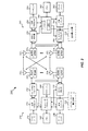
[0043]図1は、本明細書で説明する態様による、ワイヤレス通信システム100の一例を概念的に示すブロック図である。ワイヤレス通信システム100は、基地局(またはセル)105と、ユーザ機器(UE)115と、コアネットワーク130とを含む。基地局105のうちの1つまたは複数は、随意に、本明細書でさらに説明するように、複数の接続のうちの少なくとも1つのための決定された電力動作モードに基づいてトラフィックアグリゲーション中の複数の接続を介した1つまたは複数のUE115への通信をいつスケジュールすべきかを決定するためにスケジューリング構成要素520を含むことができ、および/またはそれに結合され得る。UE115のうちの1つまたは複数は、随意に、本明細書でさらに説明するように、それらの並べ替えのための1つまたは複数の接続を介した通信を受信することを容易にするためにトラフィックアグリゲーション中の複数の接続のうちの1つまたは複数を介した電力動作モードを管理するために通信構成要素540を含むことができ、および/またはそれに結合され得る。基地局105は、様々な実施形態ではコアネットワーク130または基地局105の一部であり得る、基地局コントローラ(図示せず)の制御下でUE115と通信し得る。基地局105は、第1のバックホールリンク132を通してコアネットワーク130と制御情報および/またはユーザデータを通信し得る。いくつかの実施形態では、基地局105は、ワイヤードまたはワイヤレス通信リンクであり得る第2のバックホールリンク134を介して互いに直接または間接的に通信し得る。ワイヤレス通信システム100は、複数のキャリア(異なる周波数の波形信号)上での動作をサポートし得る。マルチキャリア送信機は、複数のキャリア上で同時に変調された信号を送信し得る。たとえば、各通信リンク125は、上記で説明した様々な無線技術に従って変調されたマルチキャリア信号であり得る。各被変調信号は、異なるキャリア上で送られ得、制御情報(たとえば、基準信号、制御チャネルなど)、オーバーヘッド情報、データなどを搬送し得る。ワイヤレス通信システム100はまた、複数のフロー上での動作を同時にサポートし得る。いくつかの態様では、複数のフローは、複数のワイヤレスワイドエリアネットワーク(WWAN)またはセルラーフローに対応し得る。他の態様では、複数のフローは、WWANまたはセルラーフローとワイヤレスローカルエリアネットワーク(WLAN)またはWi−Fiフローとの組合せに対応し得る。
[0043] FIG. 1 is a block diagram conceptually illustrating an example of a
[0044]基地局105は、1つまたは複数の基地局アンテナを介してUE115とワイヤレス通信し得る。基地局105のサイトの各々は、それぞれの地理的カバレージエリア110に通信カバレージを与え得る。いくつかの実施形態では、基地局105は、基地トランシーバ局、無線基地局、アクセスポイント、無線トランシーバ、基本サービスセット(BSS)、拡張サービスセット(ESS)、ノードB、eノードB、ホームノードB、ホームeノードB、または何らかの他の好適な用語で呼ばれることがある。基地局105のための地理的カバレージエリア110は、カバレージエリアの一部分のみを構成するセクタに分割され得る(図示せず)。ワイヤレス通信システム100は、異なるタイプ(たとえば、マクロ基地局、マイクロ基地局、および/またはピコ基地局)の基地局105を含み得る。異なる技術に対して重複するカバレージエリアがあり得る。概して、基地局105−aは、WWANに対応する基地局であり得(たとえば、LTEまたはUMTSマクロセル、ピコセル、フェムトセルなどの基地局)、基地局105−bは、WLANに対応する基地局であり得る(たとえば、Wi−Fiホットスポット)。ただし、単一の基地局105が、複数のRAT(たとえば、LTEとWi−Fi、LTEとUMTS、UMTSとWi−Fiなど)を介した通信をサポートすることができることを諒解されたい。
[0044]
[0045]実装形態では、ワイヤレス通信システム100はLTE/LTE−Aネットワーク通信システムである。LTE/LTE−Aネットワーク通信システムでは、発展型ノードB(eノードB)という用語は、概して、基地局105について説明するために使用され得る。ワイヤレス通信システム100は、異なるタイプのeノードBが様々な地理的領域にカバレージを与える、異種LTE/LTE−Aネットワークであり得る。たとえば、各eノードB105は、マクロセル、ピコセル、フェムトセル、および/または他のタイプのセルに通信カバレージを与え得る。マクロセルは、比較的大きい地理的エリア(たとえば、半径数キロメートル)をカバーし得、サービスに加入しているUE115によるネットワークプロバイダとの無制限アクセスを可能にし得る。ピコセルは、比較的小さい地理的エリア(たとえば、建築物)をカバーし得、サービスに加入しているUE115によるネットワークプロバイダとの無制限アクセスを可能にし得る。フェムトセルは、比較的小さい地理的エリア(たとえば、自宅)をカバーし得、無制限アクセスに加えて、フェムトセルとの関連を有するUE115(たとえば、限定加入者グループ(CSG:closed subscriber group)中のUE115、自宅内のユーザのためのUE115など)による制限付きアクセスをも可能にし得る。マクロセルのためのeノードB105はマクロeノードBと呼ばれることがある。ピコセルのためのeノードB105はピコeノードBと呼ばれることがある。また、フェムトセルのためのeノードB105はフェムトeノードBまたはホームeノードBと呼ばれることがある。eノードB105は、1つまたは複数の(たとえば、2つ、3つ、4つなどの)セルをサポートし得る。ワイヤレス通信システム100は、UE115のうちの1つまたは複数によるLTEおよびWLANまたはWi−Fiの使用をサポートし得る。
[0045] In an implementation, the
[0046]コアネットワーク130は、第1のバックホールリンク132(たとえば、S1インターフェースなど)を介してeノードB105または他の基地局105と通信し得る。eノードB105はまた、たとえば、第2のバックホールリンク134(たとえば、X2インターフェースなど)を介しておよび/または第1のバックホールリンク132を介して(たとえば、コアネットワーク130を通して)直接または間接的に、互いに通信し得る。ワイヤレス通信システム100は同期動作または非同期動作をサポートし得る。同期動作の場合、eノードB105は同様のフレームタイミングを有し得、異なるeノードB105からの送信は近似的に時間的に整合され得る。非同期動作の場合、eノードB105は異なるフレームタイミングを有し得、異なるeノードB105からの送信は時間的に整合されないことがある。本明細書で説明する技法は、同期動作または非同期動作のいずれにも使用され得る。
[0046] The
[0047]UE115は、ワイヤレス通信システム100全体にわたって分散され得、各UE115は固定またはモバイルであり得る。UE115はまた、当業者によって、移動局、加入者局、モバイルユニット、加入者ユニット、ワイヤレスユニット、リモートユニット、モバイルデバイス、ワイヤレスデバイス、ワイヤレス通信デバイス、リモートデバイス、モバイル加入者局、アクセス端末、モバイル端末、ワイヤレス端末、リモート端末、ハンドセット、ユーザエージェント、モバイルクライアント、クライアント、または何らかの他の適切な用語で呼ばれることがある。UE115は、セルラーフォン、携帯情報端末(PDA)、ワイヤレスモデム、ワイヤレス通信デバイス、ハンドヘルドデバイス、タブレットコンピュータ、ラップトップコンピュータ、コードレスフォン、ワイヤレスローカルループ(WLL)局などであり得る。UE115は、マクロeノードB、ピコeノードB、フェムトeノードB、リレーなどと通信することが可能であり得る。
[0047] The
[0048]ワイヤレス通信システム100に示されている通信リンク125は、UE115からeノードB105へのアップリンク(UL)送信および/またはeノードB105からUE115へのダウンリンク(DL)送信を含み得る。ダウンリンク送信は順方向リンク送信と呼ばれることもあり、アップリンク送信は逆方向リンク送信と呼ばれることもある。
[0048] The
[0049]ワイヤレス通信システム100のいくつかの態様では、UE115は、2つ以上のeノードB105でキャリアアグリゲーション(CA)をサポートするように構成され得る。キャリアアグリゲーションのために使用されるeノードB105はコロケートされ得るか、または高速接続を通して接続され得る。いずれの場合も、UE115とeノードB105との間のワイヤレス通信のためのコンポーネントキャリア(CC)のアグリゲーションを協調させることは、キャリアアグリゲーションを実行するために使用されている様々なセル間で情報が容易に共有され得るので、より容易に行われ得る。キャリアアグリゲーションのために使用されるeノードB105がコロケートされない(たとえば、遠くに離れているかまたはそれらの間の高速接続を有しない)とき、コンポーネントキャリアのアグリゲーションを協調させることは、追加の態様を伴い得る。
[0049] In some aspects of the
[0050]さらに、たとえば、いくつかの基地局105は、上記で説明したようにキャリアアグリゲーションに基づいて可能になり得る、異なるRATを使用する基地局が(たとえば、所与のUE115のために)両方の基地局からのトラフィックをアグリゲートするために通信することができるように、トラフィックアグリゲーションをサポートすることができる。たとえば、UE115−aは、基地局105−aおよび基地局105−bと通信することができ、基地局105−bは、関係するWWANに通信するためにUE115−aと基地局105−aとの間のトラフィックのアグリゲーションを協調させるために基地局105−aと通信することができる。したがって、一例では、UE115−aは、1つまたは複数のトランシーバを使用して、LTE通信およびWi−Fi通信をサポートし得る。この点について、たとえば、UE115−aが、それぞれのRATを使用して異なるRANを動作させる基地局105−aと基地局105−bとに第1のワイヤレスネットワークのためのデータを通信するように、UE115−aのためのトラフィックアグリゲーションが確立され得る。基地局105−bは、関係する第1のワイヤレスネットワークにおいて通信するために、基地局105−aとの間でデータを与えることができる。この構成は、UE115−aについてスループットの増加または他の接続性プロパティの改善を可能にする。さらに、トラフィックアグリゲーションは、この点について、対応するシーケンス番号をもつパケットまたはデータユニットを有する1つまたは複数のネットワークレイヤで行われ得、したがって、パケットまたはデータユニットがUE115−aにおいて順序が乱れて受信され得、したがって、UE115−aは、パケットを並べ替えることができる。たとえば、トラフィックアグリゲーションは、MACレイヤ、RLCレイヤ、PDCPレイヤ、IPレイヤ、TCPまたはTCP/IPレイヤ、UDPまたはUDP/IPレイヤ、1つまたは複数のアプリケーションレイヤなどを介して行われ得る。
[0050] Further, for example, some
[0051]図2は、本明細書で説明する態様に従って構成されたeノードB210およびUE250の例を概念的に示すブロック図である。たとえば、図2に示されているように、システム200の基地局/eノードB210およびUE250は、それぞれ、図1中の基地局/eノードBのうちの1つおよびUEのうちの1つであり得る。したがって、基地局/eノードB210は、随意に、本明細書でさらに説明するように、複数の接続のうちの少なくとも1つのための決定された電力動作モードに基づいてトラフィックアグリゲーション中の複数の接続を介した1つまたは複数のUE250への通信をいつスケジュールすべきかを決定するためにスケジューリング構成要素520を含むことができ、および/またはそれに結合され得る。UE250は、随意に、本明細書でさらに説明するように、それらの並べ替えのための1つまたは複数の接続を介した通信を受信することを容易にするためにトラフィックアグリゲーション中の複数の接続のうちの1つまたは複数を介した電力動作モードを管理するために通信構成要素540を含むことができ、および/またはそれに結合され得る。いくつかの態様では、eノードB210は、本明細書で説明するように、トラフィックアグリゲーションをサポートし得る。いくつかの態様では、UE250も、トラフィックアグリゲーションをサポートし得る。UE250は、eノードB210または他のネットワークエンティティから、トラフィックアグリゲーションのための構成情報を受信し得る。基地局210はアンテナ2341〜tを装備し得、UE250はアンテナ2521〜rを装備し得、ここにおいて、tおよびrは1よりも大きいかまたはそれに等しい整数である。
[0051] FIG. 2 is a block diagram conceptually illustrating an example of an
[0052]基地局210において、基地局送信プロセッサ220は、基地局データソース212からデータを受信し、基地局コントローラ/プロセッサ240から制御情報を受信し得る。制御情報は、PBCH、PCFICH、物理ハイブリッド自動再送要求/要求(HARQ)インジケータチャネル(PHICH)、PDCCHなどの上で搬送され得る。データは、PDSCHなどの上で搬送され得る。基地局送信プロセッサ220は、データシンボルおよび制御シンボルを取得するために、それぞれデータおよび制御情報を処理(たとえば、符号化およびシンボルマッピング)し得る。基地局送信プロセッサ220はまた、たとえば、PSS、SSS、およびセル固有基準信号(RS:reference signal)のための、基準シンボルを生成し得る。基地局送信(TX)多重入力多重出力(MIMO)プロセッサ230は、適用可能な場合、データシンボル、制御シンボル、および/または基準シンボルにおいて空間処理(たとえば、プリコーディング)を実施し得、基地局変調器/復調器(MOD/DEMOD)2321〜tに出力シンボルストリームを与え得る。各基地局変調器/復調器232は、出力サンプルストリームを取得するために、(たとえば、OFDMなどのために)それぞれの出力シンボルストリームを処理し得る。各基地局変調器/復調器232はさらに、ダウンリンク信号を取得するために、出力サンプルストリームを処理(たとえば、アナログへの変換、増幅、フィルタ処理、およびアップコンバート)し得る。変調器/復調器2321〜tからのダウンリンク信号は、それぞれアンテナ2341〜tを介して送信され得る。
[0052] At
[0053]UE250において、UEアンテナ2521〜rは、基地局210からダウンリンク信号を受信し得、受信信号をそれぞれUE変調器/復調器(MOD/DEMOD)2541〜rに与え得る。各UE変調器/復調器254は、入力サンプルを取得するために、それぞれの受信信号を調整(たとえば、フィルタ処理、増幅、ダウンコンバート、およびデジタル化)し得る。各UE変調器/復調器254はさらに、受信シンボルを取得するために、(たとえば、OFDMなどのために)入力サンプルをさらに処理することができる。UE MIMO検出器256は、すべてのUE変調器/復調器2541〜rから受信シンボルを取得し、適用可能な場合は受信シンボルに対してMIMO検出を実行し、検出シンボルを与え得る。UE受信プロセッサ258は、検出シンボルを処理(たとえば、復調、デインターリーブ、および復号)し、UE250の復号されたデータをUEデータシンク260に与え、復号された制御情報をUEコントローラ/プロセッサ280に与え得る。
[0053] At
[0054]アップリンク上では、UE250において、UE送信プロセッサ264は、UEデータソース262から(たとえば、PUSCHのための)データを受信し、処理し得、UEコントローラ/プロセッサ280から(たとえば、PUCCHのための)制御情報を受信し、処理し得る。UE送信プロセッサ264はまた、基準信号のための基準シンボルを生成することができる。UE送信プロセッサ264からのシンボルは、適用可能な場合、UE TX MIMOプロセッサ266によってプリコーディングされ、(たとえば、SC−FDMなどのために)UE変調器/復調器2541〜rによってさらに処理され、基地局210に送信され得る。基地局210において、UE250からのアップリンク信号は、基地局アンテナ234によって受信され、基地局変調器/復調器232によって処理され、適用可能な場合は基地局MIMO検出器236によって検出され、UE250によって送られた復号されたデータと制御情報とが取得するために、基地局受信プロセッサ238によってさらに処理され得る。基地局受信プロセッサ238は、復号されたデータを基地局データシンク246に与え、復号された制御情報を基地局コントローラ/プロセッサ240に与え得る。
[0054] On the uplink, at
[0055]基地局コントローラ/プロセッサ240およびUEコントローラ/プロセッサ280は、それぞれ、基地局210およびUE250における動作を指示し得る。UE250におけるUEコントローラ/プロセッサ280ならびに/または他のプロセッサおよびモジュールはまた、たとえば、図5に示された機能ブロック、および/または本明細書で説明する技法のための他のプロセス(たとえば、図6および図8〜図10に示されたフローチャート)を実行するか、またはその実行を指示し得る。いくつかの態様では、これらの機能ブロックおよび/またはプロセスの実行の少なくとも一部分は、UEコントローラ/プロセッサ280中のブロック281によって実行され得る。基地局メモリ242およびUEメモリ282は、それぞれ基地局210およびUE250のためのデータおよびプログラムコードを記憶し得る。たとえば、UEメモリ282は、基地局210および/または別の基地局によって与えられる多重接続性についての構成情報を記憶し得る。スケジューラ244は、ダウンリンクおよび/またはアップリンク上でのデータ送信のためにUE250をスケジュールするために使用され得る。
[0055] Base station controller /
[0056]一構成では、UE250は、第1のRATを使用して第1のサービングノードとの第1の接続を確立するための手段、第2のRATを使用して第2のサービングノードとの第2の接続を確立するための手段、第1の接続のための電力消費モードの指示を受信するための手段、および/または指示に少なくとも部分的に基づいて第2の接続の電力動作モードを決定するための手段を含み得る。一態様では、上述の手段は、上述の手段によって具陳された機能を実行するように構成された、UEコントローラ/プロセッサ280、UEメモリ282、UE受信プロセッサ258、UE MIMO検出器256、UE変調器/復調器254、および/またはUEアンテナ252であり得る(および/またはそれに結合され得る)。別の態様では、上述の手段は、上述の手段によって具陳された機能を実行するように構成されたモジュール、構成要素、または任意の装置であり得る。そのようなモジュール、構成要素、または装置の例について、図5に関して説明し得る。
[0056] In one configuration, the
[0057]一構成では、基地局210は、第1のRATを使用して第1の接続を介してUEにサービスするための手段、第2のRATを使用してアクセスポイントとの第2の接続に関連する電力動作モードでUEが構成されるのかどうかを決定するための手段、UEが第2の接続に関連する電力動作モードで構成されるという決定に少なくとも部分的に基づいて第1の時間間隔中に第2の接続についてのデータをスケジュールするための手段、および/または第2の時間間隔中に第1の接続と第2の接続との上でデータをスケジュールするための手段を含み得る。基地局210はまた、第2のRATを使用するアクセスポイントを通じて第2の接続を介してUEと通信するための手段、第2の接続を介した電力動作モードを出ることを示す制御パケットを第1の接続または第2の接続を介してUEに送信するための手段、および/または制御パケットを送信することに少なくとも部分的に基づいて第1の接続および第2の接続上での送信のためのデータをスケジュールするための手段を含み得る。基地局210は、第2の接続がある電力動作モードにあるのかどうかを示す情報をアクセスポイントから受信することに少なくとも部分的に基づいて第2の接続がその電力動作モードにあるのかどうかを決定するための手段、および/または第2の接続がその電力動作モードにあるのかどうかに少なくとも部分的に基づいて第1の接続および第2の接続上での送信のためのデータをスケジュールするための手段をさらに含み得る。一態様では、上述の手段は、上述の手段によって具陳された機能を実行するように構成された、基地局コントローラ/プロセッサ240、基地局メモリ242、基地局受信プロセッサ238、基地局MIMO検出器236、基地局変調器/復調器232、および/または基地局アンテナ234であり得る(および/またはそれに結合され得る)。別の態様では、上述の手段は、上述の手段によって具陳された機能を実行するように構成されたモジュール、構成要素、または任意の装置であり得る。そのようなモジュール、構成要素、または装置の例について、図5に関して説明し得る。
[0057] In one configuration, the
[0058]図3は、本明細書で説明する態様による、UEにおける無線アクセス技術のアグリゲーションを概念的に示すブロック図である。アグリゲーションは、1つまたは複数のコンポーネントキャリア1〜N(CC1〜CCN)を使用してeノードB305−aと通信し、および/またはWLANコンポーネントキャリア340を使用してWLANアクセスポイント(AP)305−bと通信することができる、マルチモードUE315を含むシステム300中で行われ得る。eノードB305−aは、随意に、本明細書でさらに説明するように、複数の接続のうちの少なくとも1つのための決定された電力動作モードに基づいてトラフィックアグリゲーション中の複数の接続を介した1つまたは複数のUE315への通信をいつスケジュールすべきかを決定するためにスケジューリング構成要素520を含むことができ、および/またはそれに結合され得る。UE315は、随意に、本明細書でさらに説明するように、それらの並べ替えのための1つまたは複数の接続を介した通信を受信することを容易にするためにトラフィックアグリゲーション中の複数の接続のうちの1つまたは複数を介した電力動作モードを管理するために通信構成要素540を含むことができ、および/またはそれに結合され得る。マルチモードUEは、この例では、2つ以上の無線アクセス技術(RAT)をサポートするUEを指すことがある。たとえば、UE315は、少なくともWWAN無線アクセス技術(たとえば、LTE)とWLAN無線アクセス技術(たとえば、Wi−Fi)とをサポートする。マルチモードUEはまた、RATのうちの1つまたは複数を使用するキャリアアグリゲーションをサポートし得る。UE315は、図1、図2、図3、図4、および図5のUEのうちの1つの一例であり得る。eノードB305−aは、図1、図2、図3、図4、および図5のeノードBまたは基地局のうちの1つの一例であり得る。図3には、1つのUE315、1つのeノードB305−a、および1つのAP305−bのみが示されているが、システム300は、任意の数のUE315、eノードB305−a、および/またはAP305−bを含むことができることを諒解されよう。特定の一例では、UE315は、1つのLTEコンポーネントキャリア330を介して1つのeNB305と通信しながら、別のコンポーネントキャリア330を介して別のeNB305と通信することができる。
[0058] FIG. 3 is a block diagram conceptually illustrating aggregation of radio access technologies at a UE in accordance with aspects described herein. Aggregation is one or more component carriers using 1~N (CC 1 ~CC N) communicating with the e Node B 305-a, and / or using the
[0059]eノードB305−aは、LTEコンポーネントキャリアCC1〜CCN330上の順方向(ダウンリンク)チャネル332−1〜332−Nを介してUE315に情報を送信することができる。さらに、UE315は、LTEコンポーネントキャリアCC1〜CCN上の逆方向(アップリンク)チャネル334−1〜334−Nを介してeノードB305−aに情報を送信することができる。同様に、AP305−bは、WLANコンポーネントキャリア340上の順方向(ダウンリンク)チャネル352を介してUE315に情報を送信し得る。さらに、UE315は、WLANコンポーネントキャリア340の逆方向(アップリンク)チャネル354を介してAP305−bに情報を送信し得る。
[0059] The eNode B 305-a may send information to the
[0060]一例では、eNB305−aは、eNB305−aに対応するネットワークにデータを通信するためにコンポーネントキャリア330−1(および/またはコンポーネントキャリア330−1〜330−N)ならびにWLANコンポーネントキャリア340を利用するようにUE315を構成することができる。一例では、複数のWLANコンポーネントキャリア340が存在し得る。この点について、トラフィックアグリゲーションは、eNB305−aにWLANコンポーネントキャリア340を介して受信されるトラフィックを通信し、eNB305−aからWLANコンポーネントキャリア340を介してUE315にトラフィックを通信するAP305−bによって与えられる。したがって、eNB305−aは、UE315と対応するネットワークとの間の通信を容易にするために、様々なキャリア(少なくともコンポーネントキャリア330−1およびWLANコンポーネントキャリア340)を利用することができる。UE315はまた、AP305−bまたは別のWLAN APに関係する別のネットワークにアクセスするように構成され得る。説明した構成は、UE315の上位レイヤおよび/またはユーザにアグノスティックであり得るので、これは、UE315においてWLANについて予想されるネットワーク発見および選択と実際のネットワーク発見および選択との間に矛盾を生じ得る。本明細書で説明する態様は、UE315の動作を定義し、ここで、WLANコンポーネントキャリア340は、様々なコンポーネントキャリア330−1〜330−Nおよび340を使用してUE315からeNB305−aへのトラフィックアグリゲーションをサポートし、ここで、トラフィックアグリゲーションは、説明したように、順序外れに受信され得るパケットまたは他のデータユニットを並べ替えるために1つまたは複数のネットワークレイヤで行われ得る。
[0060] In one example, eNB 305-a uses component carrier 330-1 (and / or component carriers 330-1 to 330-N) and
[0061]図3ならびに開示する実施形態のうちのいくつかに関連する他の図の様々なエンティティについて説明する際、説明の目的で、3GPP LTEまたはLTE−Aワイヤレスネットワークに関連する名称が使用される。ただし、システム300は、限定はしないが、OFDMAワイヤレスネットワーク、CDMAネットワーク、3GPP2 CDMA2000ネットワークなどの他のネットワークにおいて動作することができることを諒解されたい。
[0061] In describing various entities in FIG. 3 as well as other diagrams related to some of the disclosed embodiments, for purposes of explanation, names associated with 3GPP LTE or LTE-A wireless networks are used. The However, it should be appreciated that the
[0062]図4は、本明細書で説明する態様による、UE415とEPC480との間のデータ経路445−aおよび445−bの一例を概念的に示すブロック図である。eノードB405は、随意に、本明細書でさらに説明するように、複数の接続のうちの少なくとも1つのための決定された電力動作モードに基づいてトラフィックアグリゲーション中の複数の接続を介した1つまたは複数のUE415への通信をいつスケジュールすべきかを決定するためにスケジューリング構成要素520を含むことができ、および/またはそれに結合され得る。UE415は、随意に、本明細書でさらに説明するように、それらの並べ替えのための1つまたは複数の接続を介した通信を受信することを容易にするためにトラフィックアグリゲーション中の複数の接続のうちの1つまたは複数を介した電力動作モードを管理するために通信構成要素540を含むことができ、および/またはそれに結合され得る。データ経路445−a、445−bは、eノードB405およびWLAN AP406のリソースを使用して送信するためにトラフィックをアグリゲートするためのワイヤレス通信システム401のコンテキスト内で示されている。このベアラ構成は、トラフィックアグリゲーション(たとえば、RANアグリゲーション)において、eノードB405を通過するデータ経路445−aと、WLAN AP406とeノードB405とを通過するデータ経路445−bとを含む。図2のシステム200は、ワイヤレス通信システム401の部分の一例であり得る。
[0062] FIG. 4 is a block diagram conceptually illustrating an example of data paths 445-a and 445-b between
[0063]ワイヤレス通信システム401は、UE415と、eノードB405と、WLAN AP406と、発展型パケットコア(EPC)480と、PDN440と、ピアエンティティ455とを含み得る。UE415は、本明細書で説明するように、トラフィックアグリゲーションをサポートするように構成され得るが、トラフィックアグリゲーションは、eノードB405によって制御され得、UE415の上位レイヤにアグノスティックであり得る。EPC480は、モビリティ管理エンティティ(MME)430と、サービングゲートウェイ(SGW)432と、PDNゲートウェイ(PGW)434とを含み得る。ホーム加入者システム(HSS:home subscriber system)435は、MME430に通信可能に結合され得る。UE415は、LTE無線機420とWLAN無線機425とを含み得る。UE415が1つまたは複数のそのような無線機を含むことができること、および/またはそれらの無線機が統合され得ることを諒解されたい。したがって、一例では、WLAN無線機425に加えて、LTE無線機420もWLAN無線機を含むことができ(またはWLAN信号を処理するように構成され得)、この例では、UE415は、2つのWLANインターフェース、すなわち、LTE無線機420中のWLANインターフェースとWLAN無線機425中のWLANインターフェースとを含む。これらの要素は、前または後の図を参照しながら上記で説明したそれらのカウンターパートのうちの1つまたは複数の態様を表し得る。たとえば、UE415は、図1、図2、図3、図5中のUEの一例であり得、eノードB405−aは、図1、図2、図3、図5のeノードB/基地局の一例であり得、WLAN AP406は、図1、図3、図5で説明するAPの一例であり得、および/またはEPC480は、図1のコアネットワークの一例であり得る。
[0063] The
[0064]一例では、eノードB405−aは、説明したように、1つまたは複数のLTEコンポーネントキャリアに関係し得る、PDN440へのアクセスをUE415に与えることが可能であり得る。さらに、たとえば、WLAN AP406は、eノードB405を通過することによってPDN440へのアクセスをUE415に与えることが可能であり得る。したがって、eノードB405とWLAN AP406とは、UE415との間のトラフィックをアグリゲートするために通信することができる。したがって、UE415は、一方の接続が第1のアクセスポイント(eノードB405)へのものであり、他方の接続が第2のアクセスポイント(WLAN AP406)へのものであり、第2のアクセスポイントが、UE415のためのトラフィックをアグリゲートするために第1のアクセスポイントと通信する、トラフィックアグリゲーションを伴い得る。この構成を使用して、UE415のために確立される、EPC480との(たとえば、図3に示すような)ベアラおよび/または関係するコンポーネントキャリアは、eノードB405および/またはWLAN AP406を用いたものであり得る。一例では、UE415が、EPC408とeノードB405との間で、および(eノードB405を介して)EPC480とWLAN AP406との間で確立される別個のベアラを有する、ベアラ選択が構成され得る。この例では、UE415とeノードB405/WLAN AP406との間のキャリアにマッピングすることができる、それぞれのベアラを介して、データトラフィック(たとえば、IPパケットまたは他のデータユニット)が送られる。別の例では、WLAN AP406キャリアの場合でもUE415ベアラがeノードB405EPC480の間にある、RLC/PDCPレベルアグリゲーションが構成され得る。この例では、データトラフィック(たとえば、IPパケット)は、RLC/PDCPレベルにおいてアグリゲートされ、UE415に、またはeノードB405およびWLAN AP406とのそれぞれのキャリアに通信される。
[0064] In one example, eNode B 405-a may be able to provide
[0065]たとえば、eノードB405からUE415へのダウンリンク(DL)PDCPパケットは、LTE無線機420とWLAN無線機425とによる受信のためにLTE接続とWLAN接続とにわたって分割され得る。たとえば、eノードB405は、(たとえば、eノードB405からWLAN AP406へ、次いでUE415へのデータ経路445−bをトラバースするためにWLANを介してDL PDCPパケットをスケジュールすることができる。UE415は、単独で発生するLTEリンクレイヤ送信およびWLANリンクレイヤ送信として順が狂ったPDCPパケットを受信し得る。したがって、UE415は、上位レイヤにパケットを送信する前に、シーケンス番号に基づいてPDCPレイヤにおいてパケット(説明したように、トラフィックアグリゲーション中の他のネットワークレイヤ中の他のデータユニット)を並べ替えるように構成され得る。さらに、この点について、UE415は、並べ替えキュー中に保持されたパケットをフラッシングして出し、並べ替え窓を移動するための並べ替えタイムアウトを定義することができ、消失したシーケンス番号が付けられたパケットが並べ替え穴を作成し、並べ替えタイムアウトが満了する前にUE415がそのパケットを受信しない場合、これは、上位レイヤにおいてデータ損失を作成することになる。このシナリオは、別の接続の電力消費モードに基づいて1つの接続の電力動作モードを制御する本明細書で説明する態様を使用して低減され得る。
[0065] For example, downlink (DL) PDCP packets from
[0066]図4の態様についてLTEに関して説明したが、アグリゲーションおよび/または多重接続に関する同様の態様はまた、UMTSあるいは他の同様のシステムまたはネットワークワイヤレス通信無線技術に関して実装され得る。 [0066] Although the aspects of FIG. 4 have been described with respect to LTE, similar aspects regarding aggregation and / or multiple connections may also be implemented with respect to UMTS or other similar systems or network wireless communication radio technologies.
[0067]図5は、本明細書で説明する態様に従って構成されたeノードB505、UE515、および構成要素の一例を概念的に示すブロック図500である。本明細書で図5と併せて説明する図6および図8〜図10に、本明細書で説明する態様による例示的な方法600、800、900、および1000を示す。図6および図8〜図10において以下で説明する動作は、特定の順序でおよび/または例示的な構成要素によって実行されるものとして提示されるが、アクションの順序およびアクションを実行する構成要素は、実装形態に応じて変更され得ることを理解されたい。その上、以下のアクションまたは機能は、特別にプログラムされたプロセッサ、特別にプログラムされたソフトウェアまたはコンピュータ可読媒体を実行するプロセッサによって、あるいは説明するアクションまたは機能を実行することが可能なハードウェア構成要素および/またはソフトウェア構成要素の任意の他の組合せによって実行され得ることを理解されたい。
[0067] FIG. 5 is a block diagram 500 that conceptually illustrates an example of an
[0068]図5を参照すると、ブロック図500の基地局/eノードB505、WLAN AP506、およびUE515は、様々な図で説明する基地局/eノードB、AP、および/またはUEのうちの1つであり得る。たとえば、UE515は、ワイヤレスネットワークにアクセスするためにeNB505と通信することができ、それの例について、図1〜図4において説明した。一例では、UE515は、UE115、UE250、UE315、UE415などを含み得、eNB505は、アクセスポイント105、eノードB210、eノードB305−a、eノードB405などを含み得、WLAN AP506は、アクセスポイント105、AP305−b、WLAN AP406などを含み得る。一態様では、eNB505およびUE515は、ダウンリンク信号を介してそれの上で通信するための1つまたは複数のダウンリンクチャネルを確立していることがあり、ダウンリンク信号509は、構成された通信リソース上でeNB505からUE515に(たとえば、シグナリングにおいて)制御および/またはデータメッセージを通信するために、(たとえば、トランシーバ559を介して)eNB505によって送信され、(たとえば、トランシーバ509を介して)UE515によって受信され得る。その上、たとえば、eNB505およびUE515は、アップリンク信号を介してそれの上で通信するための1つまたは複数のアップリンクチャネルを確立していることがあり、アップリンク信号は、構成された通信リソース上でUE515からeNB505に(たとえば、シグナリングにおいて)制御および/またはデータメッセージを通信するために、(たとえば、トランシーバ509を介して)UE515によって送信され、(たとえば、トランシーバ559を介して)eNB505によって受信され得る。
[0068] Referring to FIG. 5, base station /
[0069]一例では、eノードB505およびUE515は、第1の無線アクセス技術(RAT)(たとえば、LTEなどのWWAN RAT)を使用して第1の通信リンク525を介してダウンリンクおよび/またはアップリンク通信を通信し得る。WLAN AP506およびUE515はまた、第2の無線アクセス技術(RAT)(たとえば、WLAN RAT)を使用して第2の通信リンク526を介して通信し得る。図示していないが、WLAN AP506が第2のRATを使用してUE515と信号を通信するためのトランシーバをも含むことができることを諒解されたい。通信リンク525、526の各々は、図1の通信リンク125の一例であり得る。さらに、たとえば、eノードB505は、RANアグリゲーションと呼ばれることもあるトラフィックアグリゲーションを構成し、それをUE515に与えるためにWLAN AP506と通信することができ、したがって、eノードB505とWLAN AP506とを介した無線アクセスを使用することによってUE515とeノードB505に関係するネットワークとの間でトラフィックが通信され得る(たとえば、ここで、WLAN AP 506は、eノードB505とWLAN AP506との間でバックホールリンク532または他のリンクを介してUE515との間で通信するためにeノードB505との間でトラフィックを受信/提供することができる)。eノードB505および/またはWLAN AP506との接続のうちの1つまたは複数への追加または代替としてUE515について他の接続がアグリゲートされ得ることを諒解されたい。たとえば、UE515において1つまたは複数の追加または代替のRATについて他の接続がアグリゲートされ得、本明細書で説明する概念は、トラフィックアグリゲーション中のパケット損失を回避するためにRATのうちの1つまたは複数を介した電力動作モードを扱うために適用され得る。
[0069] In one example, the
[0070]一態様では、UE515は、たとえば、1つまたは複数のバス507を介して通信可能に結合され得る1つまたは複数のプロセッサ503および/またはメモリ504を含み得、(たとえば、本明細書では第1の接続とも呼ぶ第1の通信リンク525を使用して)第1のワイヤレスネットワークにアクセスするためにeノードB505のRAT(たとえば、LTE、UMTSなど)を使用する第1のアクセスポイントとしてeノードB505と通信するためと、(たとえば、本明細書では第2の接続とも呼ぶ第2の通信リンク526を使用して)第2のワイヤレスネットワークにアクセスするためにWLAN AP506のRAT(たとえば、802.11 Wi−Fi)を使用する第2のアクセスポイントとしてWLAN AP506と通信するための通信構成要素540とともに動作するか、またはさもなければそれを実装し得る。一例では、eノードB505は、説明したように、UE515が、eノードB505に関係するネットワークにアクセスするために、それぞれの第1の通信リンク525と第2の通信リンク526とを介してeノードB505とWLAN AP506の両方と通信するように、UE515のためのトラフィックアグリゲーションを構成することができる。この点について、説明したように、WLAN AP506は、第2の通信リンク526を介してUE515のためのトラフィックアグリゲーションを与えるために、バックホールリンク532を介してeノードB505とUE515トラフィックを通信することができる。
[0070] In an aspect, the
[0071]たとえば、通信構成要素540に関係する様々な動作は、1つまたは複数のプロセッサ503によって実装されるか、またはさもなければ実行され得、一態様では、単一のプロセッサによって実行され得、他の態様では、動作のうちの異なるものは2つまたはそれ以上の異なるプロセッサの組合せによって実行され得る。たとえば、一態様では、1つまたは複数のプロセッサ503は、モデムプロセッサ、またはベースバンドプロセッサ、またはデジタル信号プロセッサ、または特定用途向け集積回路(ASIC)、または送信プロセッサ、受信プロセッサ、またはトランシーバ509に関連するトランシーバプロセッサのうちのいずれか1つまたは任意の組合せを含み得る。さらに、たとえば、メモリ504は、限定はしないが、ランダムアクセスメモリ(RAM)、読取り専用メモリ(ROM)、プログラマブルROM(PROM)、消去可能PROM(EPROM)、電気的消去可能PROM(EEPROM(登録商標))、磁気ストレージデバイス(たとえば、ハードディスク、フロッピー(登録商標)ディスク、磁気ストリップ)、光ディスク(たとえば、コンパクトディスク(CD)、デジタル多用途ディスク(DVD))、スマートカード、フラッシュメモリデバイス(たとえば、カード、スティック、キードライブ)、レジスタ、リムーバブルディスク、ならびにコンピュータあるいは1つまたは複数のプロセッサ503によってアクセスされ、読み取られ得るソフトウェアおよび/またはコンピュータ可読コードまたは命令を記憶するための他の好適な媒体を含む非一時的コンピュータ可読媒体であり得る。その上、メモリ504またはコンピュータ可読記憶媒体は、1つまたは複数のプロセッサ503中に存在する、1つまたは複数のプロセッサ503の外部にある、1つまたは複数のプロセッサ503を含む複数のエンティティにわたって分散される、などであり得る。
[0071] For example, various operations related to the
[0072]特に、1つまたは複数のプロセッサ503および/またはメモリ504は、通信構成要素540またはそれの副構成要素によって定義されたアクションまたは動作を実行し得る。たとえば、1つまたは複数のプロセッサ503および/またはメモリ504は、eノードB505への第1の接続に関係する電力消費モードのインジケータを受信するためのインジケータ受信構成要素550によって定義されたアクションまたは動作を実行し得る。一態様では、たとえば、インジケータ受信構成要素550は、ハードウェア(たとえば、1つまたは複数のプロセッサ503の1つまたは複数のプロセッサモジュール)、および/あるいはメモリ504に記憶され、本明細書で説明する特別に構成されたインジケータ受信動作を実行するために1つまたは複数のプロセッサ503のうちの少なくとも1つによって実行可能なコンピュータ可読コードまたは命令を含み得る。たとえば、1つまたは複数のプロセッサ503および/またはメモリ504は、WLAN AP506への第2の接続を介した電力動作モードを管理するための電力動作モード管理構成要素552によって定義されたアクションまたは動作を実行し得る。一態様では、たとえば、電力動作モード管理構成要素552は、ハードウェア(たとえば、1つまたは複数のプロセッサ503の1つまたは複数のプロセッサモジュール)、および/あるいはメモリ504に記憶され、本明細書で説明する特別に構成された電力動作モード管理動作を実行するために1つまたは複数のプロセッサ503のうちの少なくとも1つによって実行可能なコンピュータ可読コードまたは命令を含み得る。上記で説明したように、一例では、電力消費モードは、UE515が関係する接続を介してワイヤレス通信を送信および/または受信するための電力を消費するモードに関連し得る。
[0072] In particular, one or
[0073]たとえば、1つまたは複数のプロセッサ503および/またはメモリ504は、第1の接続と第2の接続とを介して受信されたパケットを並べ替えるためのパケット並べ替え構成要素554によって定義されたアクションまたは動作を随意に実行し得、ここで、パケット並べ替え構成要素554は、受信されなかった並べ替え窓内のパケットがドロップされ得るパケット並べ替えタイマー556を含み得る。一態様では、たとえば、パケット並べ替え構成要素554は、ハードウェア(たとえば、1つまたは複数のプロセッサ503の1つまたは複数のプロセッサモジュール)、および/あるいはメモリ504に記憶され、本明細書で説明する特別に構成されたパケット並べ替え動作を実行するために1つまたは複数のプロセッサ503のうちの少なくとも1つによって実行可能なコンピュータ可読コードまたは命令を含み得る。たとえば、パケット並べ替えタイマー556は、(たとえば、UE515のメモリ504、eノードB505などの1つまたは複数のeノードBから受信されたネットワーク構成、または他のネットワークエンティティなどから構成される)構成値に基づいて初期化され得る。さらに、パケットが順が狂って受信されることが検出されるとパケット並べ替えタイマー556がトーリングされ得、パケット並べ替えタイマー556の満了に基づいて、パケット並べ替え構成要素554は、パケット並べ替えが不成功であることを示し得る(および/または順が狂ったパケットをドロップし得る)。
[0073] For example, one or
[0074]たとえば、1つまたは複数のプロセッサ503および/またはメモリ504は、eノードB505との第1の接続がある電力動作モードに入り得るDRX非アクティビティタイマー558、および/またはそれの満了の後に、eノードB505が第1の接続を介したUE515へのダウンリンク送信を開始することを可能にするためにUE515がその電力動作モードを出ることができるオン継続時間タイマー560によって定義されたアクションまたは動作を随意に実行し得る。一態様では、たとえば、DRX非アクティビティタイマー558および/またはオン継続時間タイマー560は、本明細書でさらに説明するように、ハードウェア(たとえば、1つまたは複数のプロセッサ503の1つまたは複数のプロセッサモジュール)、ならびに/あるいは初期化、トーリングなどを行うために、メモリ504に記憶され、1つまたは複数のプロセッサ503のうちの少なくとも1つによって実行可能なコンピュータ可読コードまたは命令によって実施されるか、またはさもなければそれによって管理され得る。
[0074] For example, one or
[0075]同様に、一態様では、eNB505は、たとえば、1つまたは複数のバス557を介して通信可能に結合され得る1つまたは複数のプロセッサ553および/またはメモリ555を含み得、第1の通信リンク525を介してUE515と通信することと、第2の通信リンク526を介してWLAN AP506を介してRANアグリゲーションを使用してUE515と通信することとのためのスケジューリング構成要素520とともに動作するか、またはさもなければそれを実装し得る。一例では、スケジューリング構成要素520は、たとえば、UE515に通信するためのトラフィックアグリゲーション中でWLAN AP506にデータ(たとえば、上記で説明した通り、アプリケーションレイヤ、TCPレイヤ、UDPレイヤ、IPレイヤ、PDCPレイヤ、RLCレイヤまたはMACレイヤでパケットまたは他のデータユニット)を与えること、UE515によってそれに通信されたWLAN AP506からのデータを受信することなどを行うために、バックホールリンク532を介してWLAN AP506と通信することができる。たとえば、スケジューリング構成要素520に関係する様々な機能は、1つまたは複数のプロセッサ553によって実装されるか、またはさもなければ実行され得、一態様では、単一のプロセッサによって実行され得、他の態様では、上記で説明したように、機能のうちの異なるものは2つまたはそれ以上の異なるプロセッサの組合せによって実行され得る。一例では、1つまたは複数のプロセッサ553および/またはメモリ555は、UE515の1つまたは複数のプロセッサ503および/またはメモリ504に関して上記の例に記載されているように構成され得ることを諒解されたい。
[0075] Similarly, in one aspect, the
[0076]一例では、1つまたは複数のプロセッサ553および/またはメモリ555は、スケジューリング構成要素520またはそれの副構成要素によって定義されたアクションまたは動作を実行し得る。たとえば、1つまたは複数のプロセッサ553および/またはメモリ555は、WLAN AP506とUE515との間の接続(たとえば、通信リンク526を介した接続)がある電力動作モードにあるのかどうかを決定するための電力動作モード決定構成要素522によって定義されたアクションまたは動作を実行し得る。一態様では、たとえば、電力動作モード決定構成要素522は、ハードウェア(たとえば、1つまたは複数のプロセッサ553の1つまたは複数のプロセッサモジュール)、および/あるいはメモリ555に記憶され、本明細書で説明する特別に構成された電力動作モード決定動作を実行するために1つまたは複数のプロセッサ553のうちの少なくとも1つによって実行可能なコンピュータ可読コードまたは命令を含み得る。たとえば、1つまたは複数のプロセッサ553および/またはメモリ555は、WLAN AP506とUE515との間の接続がその電力動作モードにあるのかどうかに少なくとも部分的に基づいてWLAN AP506とUE515との間および/またはeノードB505とUE515との間の接続を介してデータをスケジュールするためのデータスケジューリング構成要素524によって定義されたアクションまたは動作を実行し得る。一態様では、たとえば、データスケジューリング構成要素524は、ハードウェア(たとえば、1つまたは複数のプロセッサ553の1つまたは複数のプロセッサモジュール)、および/あるいはメモリ555に記憶され、本明細書で説明する特別に構成されたデータスケジューリング動作を実行するために1つまたは複数のプロセッサ553のうちの少なくとも1つによって実行可能なコンピュータ可読コードまたは命令を含み得る。
[0076] In one example, one or
[0077]たとえば、1つまたは複数のプロセッサ553および/またはメモリ555は、UE515と通信するためのバッファに関係するバッファサイズを決定するためのバッファサイズ決定構成要素527によって定義されたアクションまたは動作を随意に実行し得る。一態様では、たとえば、バッファサイズ決定構成要素527は、ハードウェア(たとえば、1つまたは複数のプロセッサ553の1つまたは複数のプロセッサモジュール)、および/あるいはメモリ555に記憶され、本明細書で説明する特別に構成されたバッファサイズ決定動作を実行するために1つまたは複数のプロセッサ553のうちの少なくとも1つによって実行可能なコンピュータ可読コードまたは命令を含み得る。たとえば、1つまたは複数のプロセッサ553および/またはメモリ555は、UE515にその電力動作モードを出るためのインジケータを送信するためのインジケータ送信構成要素528によって定義されたアクションまたは動作を随意に実行し得る。一態様では、たとえば、インジケータ送信構成要素528は、ハードウェア(たとえば、1つまたは複数のプロセッサ553の1つまたは複数のプロセッサモジュール)、および/あるいはメモリ555に記憶され、本明細書で説明する特別に構成されたインジケータ送信動作を実行するために1つまたは複数のプロセッサ553のうちの少なくとも1つによって実行可能なコンピュータ可読コードまたは命令を含み得る。たとえば、1つまたは複数のプロセッサ553および/またはメモリ555は、WLAN AP506からその電力動作モードの情報を受信するためのモード情報受信構成要素530よって定義されたアクションまたは動作を随意に実行し得る。一態様では、たとえば、モード情報受信構成要素530は、ハードウェア(たとえば、1つまたは複数のプロセッサ553の1つまたは複数のプロセッサモジュール)、および/あるいはメモリ555に記憶され、本明細書で説明する特別に構成されたモード情報受信動作を実行するために1つまたは複数のプロセッサ553のうちの少なくとも1つによって実行可能なコンピュータ可読コードまたは命令を含み得る。
[0077] For example, one or
[0078]トランシーバ509、559は、1つまたは複数のアンテナ、RFフロントエンド、1つまたは複数の送信機、および1つまたは複数の受信機を通してワイヤレス信号を送信および受信するように構成され得ることを諒解されたい。一態様では、トランシーバ509、559は、UE515および/またはeNB505がある周波数において通信することができるように、指定された周波数において動作するように同調させられ得る。一態様では、関係するアップリンク通信チャネルまたはダウンリンク通信チャネル上で、それぞれ、アップリンク信号および/またはダウンリンク信号を通信するために、構成、通信プロトコルなどに基づいて指定された周波数および電力レベルにおいて動作するように、1つまたは複数のプロセッサ503がトランシーバ509を構成し得、および/あるいは1つまたは複数のプロセッサ553がトランシーバ559を構成し得る。
[0078] The
[0079]一態様では、トランシーバ509、559は、トランシーバ509、559を使用して送受信されるデジタルデータを処理するように、(たとえば、マルチバンドマルチモードモデム(図示せず)を使用して)複数の帯域サッチで動作し得る。一態様では、トランシーバ509、559は、マルチバンドであり、特定の通信プロトコルのための複数の周波数帯域をサポートするように構成され得る。一態様では、トランシーバ509、559は、複数の動作ネットワークおよび通信プロトコルをサポートするように構成され得る。したがって、たとえば、トランシーバ509、559は、指定されたモデム構成に基づいて信号の送信および/または受信を可能にし得る。
[0079] In an aspect, the
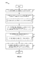
[0080]図6に、1つまたは複数のトラフィックアグリゲート接続のための電力動作モードを(たとえば、UEによって)決定するための方法600を示す。説明したように、eノードB505が、eノードB505およびWLAN AP506への接続を管理することができるので、トラフィックアグリゲーションを与えることは、eノードB505に関係するネットワークとのUE515の接続性を改善することができる。したがって、方法600は、ブロック610において、第1のサービングノードとの第1の接続を確立することを含む。一態様では、通信構成要素540は、たとえば、1つまたは複数のプロセッサ503、メモリ504、および/またはトランシーバ509と併せて、第1のサービングノード(たとえば、eノードB505)との第1の接続(たとえば、通信リンク525)を確立することができる。たとえば、通信構成要素540は、第1のRAT(たとえば、LTEまたは他のUMTSまたはセルラー技術など)を使用して第1の接続を確立することができる。一例では、通信構成要素540は、eノードB505とのランダムアクセス手順を実行することができるか、またはさもなければそれとの接続の確立を要求することができる。
[0080] FIG. 6 illustrates a
[0081]方法600はまた、ブロック612において、第2のサービングノードとの第2の接続を確立することを含み、ここで、第2の接続は、第1の接続とのトラフィックアグリゲーションのために構成される。たとえば、通信構成要素540は、たとえば、1つまたは複数のプロセッサ503、メモリ504、および/またはトランシーバ509と併せて、第2のサービングノード(たとえば、WLAN AP506、別のeノードBまたはセルなど)との第2の接続(たとえば、通信リンク526)を確立することができ、ここで、第2の接続は、第1の接続とのトラフィックアグリゲーションのために構成される。一例では、通信構成要素540は、第1のRATを使用してまたは第2のRAT(たとえば、Wi−Fi)を使用して第2の接続を確立することができる。通信構成要素540は、たとえば、WLAN AP506との接続を要求し、それとの任意の課金/認証手順を実行することなどに基づいて第2の接続を確立することができる。一例では、eノードB505は、説明したように、WLAN AP506を介したトラフィックアグリゲーションを与えるためにUE515とWLAN AP506との間の接続を容易にすることができる。たとえば、eノードB505は、UE515に、WLAN AP506との第2の接続を確立するように命令すること、第2の接続確立するための命令を与えることなどを行い得る。いずれの場合も、UE515は、第2の接続を介してWLAN AP506と通信することができ、WLAN AP506は、説明したように、eノードB505にデータUE515を通信し得、ここで、第1の接続と第2の接続とは、トラフィックアグリゲーションを与えるように構成される。
[0081] The
[0082]さらに、説明したように、通信構成要素540は、トラフィックアグリゲーション中で、通信リンク525を介してeノードB505から、通信リンク526を介してWLAN AP506からデータを受信することができ、パケット並べ替え構成要素554は、複数のリンクを介してパケットを同時に受信することにより順が狂って受信され得るパケットを並べ替えることができる。たとえば、データは、PDCPレイヤにおいてリンクを介して分割され得、したがって、パケット並べ替え構成要素554は、それに関連するPDCPシーケンス番号に少なくとも部分的に基づいてパケットを並べ替えることができる。
[0082] Further, as described, the
[0083]方法600はまた、ブロック614において、第1の接続のための電力消費モードの指示を受信することを含み得る。たとえば、指示受信構成要素550は、たとえば、1つまたは複数のプロセッサ503、メモリ504、および/またはトランシーバ509と併せて、第1の接続のための電力消費モードの指示を受信することができる。上記で説明し、本明細書でさらに説明するように、電力消費モードの指示は、データを受信するための電力の消費量がUE515において推論され得る実質的に任意の指示に関係することができる。指示は、たとえば、データが第1の接続を介して受信されていることまたは受信されるべきであること、および/あるいは第2の接続がUE515へのデータの送信をアグリゲートするために使用され得ることを示すことができる。
[0083] The
[0084]いずれの場合も、方法600はまた、ブロック616において、指示に少なくとも部分的に基づいて第2の接続の電力動作モードを決定することを含む。たとえば、電力動作モード管理構成要素552は、たとえば、1つまたは複数のプロセッサ503、メモリ504、および/またはトランシーバ509と併せて、指示に少なくとも部分的に基づいて第2の接続の電力動作モードを決定することができる。たとえば、電力動作モードを決定する際に、電力動作モード管理構成要素552は、ある電力動作モードを出ること(たとえば、アイドルモード、省電力モードまたはUE515における電力消費量を節約することに関係する他のモードに入ること)を決定することができ、ここで、指示は、第1の接続および/または場合によっては第2の接続を介して通信を受信することに関係する。この点について、たとえば、第2の接続を介した電力動作モードは、RANアグリゲーションのために望まれるとき、第2の接続を介して通信を受信するためにサッチ終了され得る。
[0084] In any case, the
[0085]したがって、一例では、ブロック614において電力消費モードの指示を受信することは、ブロック618において、第1および/または第2の接続を介して受信されたパケットを並べ替えることに関係する並べ替えステータスを決定することを随意に含み得る。一態様では、インジケータ受信構成要素550は、たとえば、1つまたは複数のプロセッサ503、メモリ504、および/またはトランシーバ509と併せて、第1および/または第2の接続を介して受信されたパケットを並べ替えることに関係する並べ替えステータスを決定することができる。たとえば、パケット並べ替え構成要素554は、並べ替えステータスを生成することができ、これは、(たとえば、パケット並べ替えタイマー556の満了の前に)複数のパケットが正常に並べ替えられているかどうか、パケット並べ替えタイマー556の値、パケット並べ替えタイマー556が満了したのかどうかの指示などを示すことができる。この場合、たとえば、電力動作モード管理構成要素552は、(たとえば、WLANリンクについて)その電力動作モードを出ることを決定することができ、ここで、インジケータ受信構成要素550は、並べ替えが不成功であると見なされる前に(たとえば、パケット並べ替えタイマー556が満了する前に)WLAN AP506において第2の接続について保留中の通信を受信しようとする試みにおいて、並べ替えステータスが不成功であることを決定すること、パケット並べ替えタイマー556が、しきい値(たとえば、満了値、満了値からの差など)に達したかまたは満了したと決定すること、あるいは並べ替えられるのを待つメモリ中のトラフィックの量に基づいて決定することなどのうちの少なくとも1つを行う。
[0085] Thus, in one example, receiving an indication of a power consumption mode at
[0086]一例では、電力動作モード管理構成要素552は、通信リンク526を介して通信する通信構成要素540のインターフェースが第2の接続のための電力動作モードに入るときをパケット並べ替え構成要素554に通知することができる。一例では、パケット並べ替え構成要素554は、eノードB505およびWLAN AP506から受信されたパケットを並べ替えるためにPDCPまたはMACレイヤにおいて動作する。パケット並べ替えタイマー556がトーリングしており、第2の接続がその電力動作モードにある(たとえば、通信構成要素540の関連するインターフェースがその電力動作モードにある)とパケット並べ替え構成要素554が決定する場合、パケット並べ替え構成要素554は、通信構成要素540に、第2の接続を介してその電力動作モードを出ること(たとえば、通信を受信するためにアクティブモードに遷移すること)、(たとえば、PS−Poll機構を介して)バッファデータについてWLAN AP506をポーリングすることなどを行うように命令することができる。これは、たとえば、パケット並べ替えタイマー556がある値に達すること、パケット並べ替えタイマー556の満了、パケット並べ替えタイマー556がトーリングし始めることなどのうちの少なくとも1つをパケット並べ替え構成要素554が決定することに基づいて行われ得る。いずれの場合も、その電力動作モードを出ること、バッファデータに対するポーリングなどにより、UE515は、パケット並べ替えタイマー556の満了(および場合によっては、順が狂ったパケットのドロップ)の前にWLAN AP506からバッファPDCPパケットを受信することが可能になり得、したがって、データ損失を回避し、さらに、並べ替えられたストリームを早期に配信することができ、これは、メモリ消費を最小化し、ユーザエクスペリエンスを改善する。PS−Pollを使用する替わりに、デバイスは、省電力モードを出るためにWLANアップリンク上でデータトラフィックを一時的にスケジュールし得る。その電力動作モードを出たことを示す省電力制御がユーザデータ上にピギーバックされ得るので、これはPSポールを使用するよりも効率的であり得る。
[0086] In one example, the power operation
[0087]これの特定の例を図7に示し、これに、UE702とWLAN AP706とeノードB704との間でパケットを通信するための例示的なシステム700を示す。システム700では、UE WLAN STAインターフェースは、710において、WLAN AP706と省電力モードに入る。WLAN AP 706は、(たとえば、70msのビーコン間隔および/または280msのDTIM間隔で)ビーコンTIMを周期的に送信する。たとえば、WLAN APは、0(トラフィック無し)を示すビーコンTIM712を送信する。714において、eノードB704は、WLAN AP706によって送信するためのシーケンス番号7、11、および12と、eノードB704によって送信するための12、14、および15とを含む、様々なPDCPパケットをスケジュールする。WLAN AP706がUE702とともに省電力モードにあるので、省電力モードが終了されるまで、パケット7、11、および12は、716において、バッファされる。一方、eノードB704は、718において、UE702にパケット13、14、および15を送信する。UE702は、722において、eノードB704から順が狂ったパケットを受信することに基づいて(たとえば、および/または少なくともしきい値時間が並べ替えタイマーに残っていると検出することに基づいて)並べ替えタイマー満了の前にある時間が残っている状態で、アクティブモードに遷移すること(たとえば、省電力モードを終了すること)ができる。したがって、724において、バッファパケット7、11、および12が受信され、並べ替え穴がデータ損失なしでフィルされる。
[0087] A specific example of this is shown in FIG. 7, which illustrates an
[0088]さらに、たとえば、ブロック614において電力消費モードの指示を受信することは、ブロック620において、第1および/または第2の接続を介して受信されたパケットが正常に並べ替えられているかどうかを決定することを随意に含み得る。一態様では、インジケータ受信構成要素550は、たとえば、1つまたは複数のプロセッサ503、メモリ504、および/またはトランシーバ509と併せて、第1および/または第2の接続を介して受信されたパケットが正常に受信されているかどうか(たとえば、シーケンス番号中のギャップがフィルされたのかどうか)を決定することができる。たとえば、インジケータ受信構成要素550は、パケット並べ替え構成要素554が、通信リンク525および526を介して受信されたパケットを並べ替えようと試み、(たとえば、パケット並べ替えタイマー556の満了に基づいて)パケットが正常に並べ替えられているおよび/または正常に並べ替えられることができないときにインジケータ受信構成要素550に通知することに少なくとも部分的に基づいてこの決定を行うことができる。さらに、一例では、パケット並べ替え構成要素554がパケット並べ替えの成功をインジケータ受信構成要素550に通知する場合、インジケータ受信構成要素550は、電力動作モード管理構成要素552に、通信構成要素540が第2の接続を介してその電力動作モードに入り得ること(たとえば、第2の接続に関係するインターフェースがある電力動作モードに入り得ること)を命令することができ、これは、電力動作モード管理構成要素552における他の考慮事項の対象となり得る。
[0088] Further, for example, receiving an indication of a power consumption mode at
[0089]さらに、たとえば、LTEは、UE515においてある電力動作モード(たとえば、電力節約モード)を有効化するためにDRXを利用することができ、ここで、eノードB505とUE515とは、DRXに対して同じ状態機械を維持し、これにより、eノードB505がUE515に時々送信することが可能になり、UE515が他の時間にスリープすること(たとえば、無線リソースを中断すること)が可能になる。したがって、一例では、電力動作モード管理構成要素552は、第1の接続のための電力動作モード(たとえば、DRX)に少なくとも部分的に基づいて第2の接続のための電力動作モードを管理することができる。DRXは様々なタイマーを定義し、それらのうちの1つがトーリングしていると、UE515は、スリープすること(たとえば、第1の接続のための無線リソースを中断すること)ができない。これらのタイマーは、UE515がダウンリンク送信を受信するようにeノードB505によって(たとえば、スケジューリング構成要素520によって)スケジュールされたときに開始するDRX非アクティビティタイマー558と、DRXサイクルごとに周期的に動作するオン継続時間タイマー560とを含む。
[0089] Further, for example, LTE may utilize DRX to enable a certain power operation mode (eg, power saving mode) at
[0090]したがって、この例では、ブロック614において電力消費モードの指示を受信することは、ブロック622において、第1のRATについての別の電力動作モードに入ることに関係する第1のRATのDRX非アクティビティタイマーがトーリングしているのかどうかを決定することを随意に含み得る。一態様では、インジケータ受信構成要素550は、たとえば、1つまたは複数のプロセッサ503、メモリ504、および/またはトランシーバ509と併せて、(たとえば、通信リンク525を介して)第1のRATについての別の電力動作モードに入ることに関係する第1のRATのDRX非アクティビティタイマー558がトーリングしているのかどうかを決定することができる。たとえば、トーリングは、タイマーをある値に初期化し、下限として0(たとえば、ここで、タイマーがカウントダウンし、したがって、トーリングは時間にわたってタイマー値を減少させる)または上限としてタイマー値(たとえば、ここで、タイマーがカウントアップし、したがって、トーリングは時間にわたってタイマー値を増加させる)に達するまで対応するプロセッサのクロックに基づいてタイマーを増分/減分されることを指すことができる。ダウンリンク送信がeノードB505から受信されると、通信構成要素540は、DRX非アクティビティタイマー558を開始/再開することができる。したがって、インジケータ受信構成要素550は、DRX非アクティビティタイマーがトーリングしていると決定する場合、第2の接続を介した電力動作モードを出るように電力動作モード管理構成要素552に命令することができる。電力動作モード管理構成要素552は、通信構成要素540に、(たとえば、第2の接続に関係するインターフェースを介して)その電力動作モードを出ること、第2の接続を介してWLAN AP506へのPS−Pollを実行することなどを行わせることができる。これにより、eノードB505からのダウンリンク送信の受信としてパケットの並べ替えの不成功を回避することができ、これは、DRX非アクティビティタイマー558のトーリングを生じ、第2の接続を介した電力動作モードを出ることに結果する。さらに、たとえば、インジケータ受信構成要素550は、最初に、電力動作モード管理構成要素552にその電力動作モードを出るように命令する前にトーリングを開始するために(アップリンク送信を送信することとは対照的に)ダウンリンク送信を受信することがDRX非アクティビティタイマー558を生じたと決定し得る。
[0090] Thus, in this example, receiving an indication of the power consumption mode at
[0091]別の例では、ブロック614において電力消費モードの指示を受信することは、ブロック624において、第1のRATについての別の電力動作モードを出ることに関係する第1のRATのオン継続時間タイマーが満了したのかどうかを決定することを随意に含み得る。一態様では、インジケータ受信構成要素550は、たとえば、1つまたは複数のプロセッサ503、メモリ504、および/またはトランシーバ509と併せて、(たとえば、通信リンク525を介して)第1のRATについての別の電力動作モードを出ることに関係する第1のRATのオン継続時間タイマー560が満了したのかどうかを決定することができる。たとえば、オン継続時間タイマー560は、eノードB505に、DRXサイクルごとに周期的にUE515へのダウンリンク送信を開始することを可能にするために、UE515に、第1の接続を介した電力動作モードを出ることを行わせることができる。したがって、このタイマー560が満了すると、電力動作モード管理構成要素552は、(たとえば、通信構成要素540に、関係するインターフェース上の電力動作モードを出るように命令することによって)第1の接続のための電力動作モードを出る。したがって、インジケータ受信構成要素550は、オン継続時間タイマー560の満了を決定する場合、電力動作モード管理構成要素552に、(たとえば、第2の接続に関係するインターフェースを介して)第2の接続のための電力動作モードを出ること、第2の接続を介してWLAN AP506へのPS−Pollを実行することなどを命令することができる。説明したように、これにより、オン継続時間タイマー560の満了に基づいて第1の接続が活動化されるとき第2の接続が活動化されるので、パケットの並べ替えの不成功を回避することができる。図示していないが、第2の接続を介して送信するためのWLAN AP506への通信をいつ送信すべきかを決定するために(たとえば、UE515と同様のDRX状態機械を与える際に)同様のDRX非アクティビティタイマーとオン継続時間タイマーとをeノードB505が管理することができることを諒解されたい。
[0091] In another example, receiving an indication of a power consumption mode at
[0092]さらなる一例では、ブロック614において電力消費モードの指示を受信することは、ブロック626において、1つまたは複数のパケットが第1の接続を介して受信されるのかどうかを決定することを随意に含み得る。一態様では、インジケータ受信構成要素550は、たとえば、1つまたは複数のプロセッサ503、メモリ504、および/またはトランシーバ509と併せて、1つまたは複数のパケットが第1の接続を介して受信されるのかどうかを決定することができ、これは、通信構成要素540からのそのような情報を決定することを含むことができる。1つまたは複数のパケットが第1の接続を介して通信構成要素540によって受信されるとインジケータ受信構成要素550が決定すると、たとえば、インジケータ受信構成要素550は、電力動作モード管理構成要素552に、(たとえば、第2の接続に関係するインターフェースを介して)第2の接続のための電力動作モードを出ること、第2の接続を介してWLAN AP506へのPS−Pollを実行することなどを命令することができる。これにより、パケットが第1の接続を介して受信されるときに第2の接続が活動化されるのでパケットの並べ替えの不成功を回避することができ、したがって、パケットは、おそらくパケット並べ替えタイマー556の満了の前にも第2の接続を介して受信され得る。
[0092] In a further example, receiving the power consumption mode indication at
[0093]さらに、別の例では、ブロック614において電力消費モードの指示を受信することは、ブロック628において、第1および/または第2の接続を介して制御パケット中で指示を受信することを随意に含み得る。一態様では、インジケータ受信構成要素550は、たとえば、1つまたは複数のプロセッサ503、メモリ504、および/またはトランシーバ509と併せて、第1および/または第2の接続を介して制御パケット(たとえば、PDCP制御PDU)中で指示を受信することができる。以下でさらに詳細に説明するように、eノードB505(および/またはWLAN AP506)は、UE515に制御パケット中で指示を送信し得る。たとえば、eノードB505(および/またはWLAN AP506)は、UE515を送信するためのデータバーストを取得することに基づいて(および/またはバーストを送信するとともに)制御パケットを送信し得る。一例では、バーストの開始は、制御パケットを含み得る。いずれの場合も、インジケータ受信構成要素550が制御パケットを受信すると、インジケータ受信構成要素550は、電力動作モード管理構成要素552に、(たとえば、第2の接続に関係するインターフェースを介して)第2の接続のための電力動作モードを出ること、第2の接続を介してWLAN AP506へのPS−Pollを実行することなどを命令することができる。たとえば、制御パケットは、電力動作モードを出る時間、電力動作モードに入る/出ることの周期的パターンなどを指定し得、したがって、インジケータ受信構成要素550は、指示に基づいて電力動作モード管理構成要素552に命令することができる。いずれの場合も、eノードB505(および/またはWLAN AP506)が、UE515に、それが第2の接続を介して送信すべきデータを有するときに第2の接続を介した電力動作モードを出ることを行なわせることができるので、これにより、パケットの並べ替えの不成功を回避することができる。さらに、たとえば、電力動作モード管理構成要素552は、少なくとも、第2の接続を介した電力動作モードに入ることをUE515が許可されることを示す制御パケットが受信されるまで、第2の接続がその電力動作モードを避けるように管理し得る。
[0093] Further, in another example, receiving an indication of a power consumption mode at
[0094]図8に、接続がある電力動作モードにあり得る、トラフィックアグリゲーション中の接続を介してデータをいつスケジュールすべきかを(たとえば、eNBによって)決定するための例示的な方法800を示す。方法800は、ブロック810において、第1のRATを使用して第1の接続を介してUEにサービスすることを含む。一態様では、スケジューリング構成要素520は、たとえば、1つまたは複数のプロセッサ553、メモリ555、および/またはトランシーバ559と併せて、第1のRAT(たとえば、LTEあるいは他のUMTSまたはセルラー技術)を使用して第1の接続(たとえば、通信リンク525)を介してUE515にサービスすることができる。たとえば、説明したように、UE515は、ランダムアクセス手順を実行するか、またはさもなければeノードB505と通信するためのリソースを要求し得、eノードB505は、それに応じて、通信リンク525を介してUE515にリソースを許可し得る。さらに、説明したように、スケジューリング構成要素520は、バックホールリンク534を介してWLAN AP506との間でデータを通信することに少なくとも部分的に基づいてUE515とWLAN AP506との間に確立される別の通信リンク526を介してUE515へのトラフィックをアグリゲートし得る。
[0094] FIG. 8 illustrates an
[0095]方法800はまた、ブロック812において、UEが第2のRATを使用したアクセスポイントとの第2の接続に関連する電力動作モードで構成されているのかどうかを決定することを含む。一態様では、電力動作モード決定構成要素522は、たとえば、1つまたは複数のプロセッサ553、メモリ555、および/またはトランシーバ559と併せて、UE(たとえば、UE515)が、第2のRAT(たとえば、Wi−Fi)を使用したアクセスポイント(たとえば、WLAN AP506)との第2の接続(たとえば、通信リンク526)に関連する電力動作モードに構成されているのかどうかを決定することができる。たとえば、電力動作モード決定構成要素522は、WLAN AP506および/またはUE515からUE515がその電力動作モードにあるのかどうかの指示を受信し得、これは、WLAN AP506および/またはUE515への要求あるいは(たとえば、UE515が第2の接続を介した電力動作モードを入ったときにWLAN AP506またはUE515から受信される通知)などに基づき得る。
[0095] The
[0096]別の例では、ブロック812においてUE515が第2の接続を介した電力動作モードで構成されているのかどうかを決定することは、ブロック814において、UEに送信するために利用可能なデータバッファのサイズを決定することをナイ含む。一態様では、バッファサイズ決定構成要素527は、たとえば、1つまたは複数のプロセッサ553、メモリ555、および/またはトランシーバ559と併せて、UE515を送信するために利用可能なデータバッファのサイズを決定することができる。たとえば、バッファサイズ決定構成要素527は、(たとえば、バッファの利用可能な容量サイズがしきい値以下であるか、またはある時間期間にわたって低くなる傾向があるなどの場合)電力動作モードが推論され得るバッファの利用可能な容量サイズを決定することができる。たとえば、バッファは、概して、第2の接続に、またはUE515のための通信に対応し得る。
[0096] In another example, determining whether the
[0097]方法800はまた、ブロック816において、UEが、第2の接続に関連する電力動作モードに構成されているという決定に少なくとも部分的に基づいて第1の時間間隔中に第2の接続についてのデータをスケジュールすることを含み得る。一態様では、データスケジューリング構成要素524は、たとえば、1つまたは複数のプロセッサ553、メモリ555、および/またはトランシーバ559と併せて、UE(たとえば、UE515)が第2の接続に関連する電力動作モードに構成されているという決定に少なくとも部分的に基づいて、第1の時間間隔中に第2の接続(たとえば、通信リンク526)のためのデータをスケジュールすることができる。たとえば、データスケジューリング構成要素524は、(たとえば、電力動作モード決定構成要素522による決定などに基づいて)UE515が第2の接続のための電力動作モードに入ったと仮定することができ、それに応じて、その時間間隔中に通信リンク526を介して送るためのデータをスケジュールすることができる(したがって、通信リンク525を介してデータは送られない)。データは、次いで、UE515がその電力動作モードを出るまでWLAN AP506によってバッファされ得る。具体的には、一例では、通信構成要素540は、その電力動作モードで信号を周期的に受信し得、(たとえば、上記の図7で説明したように)TIMについて検査し得る。この点について、TIMビットマップは、WLAN APによる送信のために利用可能なデータを示すことができ、電力動作モード管理構成要素552は、それに応じて、バッファデータを受信するために第2の接続との電力動作モードを出ることができる。
[0097] The
[0098]方法800はまた、ブロック818において、第2の時間間隔中に第1の接続と第2の接続との上でデータをスケジュールすることを含む。一態様では、データスケジューリング構成要素524は、たとえば、1つまたは複数のプロセッサ553、メモリ555、および/またはトランシーバ559と併せて、第2の時間間隔中に第1の接続と第2の接続との上でデータをスケジュールすることができる。ブロック818において第2の時間間隔中に第1の接続と第2の接続との上でデータをスケジュールすることは、ブロック820において、UEが第2の接続を介した電力動作モードを出ると決定することを随意に含み得る。たとえば、電力動作モード決定構成要素522は、(たとえば、上記で説明したように、WLAN AP506、UE515などから指示を受信すること、UE515のための利用可能なバッファ容量が増加したかまたは増加していると決定することなどに基づいて)UE515が第2の接続を介した電力動作モードを出たと決定し得る。この決定に基づいて、たとえば、データスケジューリング構成要素524は、第2の時間間隔が始まったと決定することができ、ここで、第2の接続は、UE515において電力動作モードにもはやなく、したがって、データを第2の接続を介して送ることができる。したがって、データスケジューリング構成要素524は、さらに、トラフィックアグリゲーションを実施するように第1の接続を介してデータをスケジュールする。
[0098] The
[0099]さらに、eノードB505は、UE515が第2の時間間隔中に第2の接続のための電力動作モードに再び入らないことを保証しようと試みることができる。したがって、方法800は、ブロック822において、第2の時間間隔の継続時間の間第2の接続をその電力動作モードから離れたままにするために、第2のRATに関係する非アクティビティタイマー間隔中に第2の接続上で少なくとも1つのパケットをスケジュールすることを随意に含み得る。一態様では、データスケジューリング構成要素524は、たとえば、1つまたは複数のプロセッサ553、メモリ555、および/またはトランシーバ559と併せて、第2の接続をその電力動作モードから離れたままにするために、第2のRATに関係する非アクティビティタイマー間隔中に第2の接続(たとえば、WLAN AP506へのバックホールリンク534通信を介した通信リンク526)上で少なくとも1つのパケットをスケジュールすることができる。たとえば、eノードB505は、UE515が第2のRATに基づいて第2の接続のための電力動作モードに入ることができる非アクティビティタイマー値を知ることができ、したがって、少なくとも1つのパケットは、UE515においてその電力動作モードに入ることを回避するためにこの非アクティビティ時間間隔の内側にスケジュールされる。一例では、eノードB505は、(たとえば、RRCシグナリングを介して)UE515の非アクティビティタイマー値を構成することができる。非アクティビティタイマー値は、具体的には、トラフィックアグリゲーション中の1つまたは複数の接続を介して決定された非アクティビティのために使用され得る。さらに、たとえば、データスケジューリング構成要素524は、UE515が(たとえば、非アクティビティタイマーの満了の後に)もう一度その電力動作モードに入ることを可能にするために、ある時間期間後におよび/またはイベント(たとえば、UE515に送信することに関係するバッファの利用可能な容量がしきい値を達成すること)に基づいて第2の接続上で少なくとも1つのパケットをスケジュールするのを中止し得る。
[0099] Further, the
[00100]図9に、UEに、トラフィックアグリゲーション中の接続を介した電力動作モードを出ることを行わせるために(たとえば、eNBまたはeノードBによって)UEに制御パケットを送信するための例示的な方法900を示す。方法900は、ブロック910において、第1のRATを使用して第1の接続を介してUEにサービスすることを含む。一態様では、スケジューリング構成要素520は、たとえば、1つまたは複数のプロセッサ553、メモリ555、および/またはトランシーバ559と併せて、第1のRAT(たとえば、LTEあるいは他のUMTSまたはセルラー技術)を使用して第1の接続(たとえば、通信リンク525)を介してUE515にサービスすることができる。たとえば、説明したように、UE515は、ランダムアクセス手順を実行するか、またはさもなければeノードB505と通信するためのリソースを要求し得、eノードB505は、それに応じて、通信リンク525を介してUE515にリソースを許可し得る。
[00100] FIG. 9 illustrates an example for sending a control packet to a UE (eg, by an eNB or eNodeB) to cause the UE to exit a power mode of operation via a connection during traffic aggregation. An
[00101]方法900はまた、ブロック912において、第2のRATを使用するアクセスポイントを通じた第2の接続を介してUEと通信することを含む。一態様では、スケジューリング構成要素520は、たとえば、1つまたは複数のプロセッサ553、メモリ555、および/またはトランシーバ559と併せて、第2のRATを使用するアクセスポイント(たとえば、WLAN AP506)を通じて第2の接続(たとえば、通信リンク526)を介してUE(たとえば、UE515)と通信することができる。説明したように、たとえば、スケジューリング構成要素520は、バックホールリンク534を介してWLAN AP506との間でデータを通信することに少なくとも部分的に基づいてUE515とWLAN AP506との間に確立される別の通信リンク526を介してUE515へのトラフィックをアグリゲートし得る。さらにまたは代替として、スケジューリング構成要素520は、データレートがしきい値を下回ると決定されると、低減された数の無線リンクを使用することを決定し得る。これは、複数の無線リンクにわたって省電力状態を同期させる問題を回避または低減する。たとえば、しきい値は、リンク、1つまたは複数のリンクを与える無線に対する負荷、または同様の無線品質メトリックのうちの1つまたは複数に対して達成可能なリンク容量に依存し得る。
[00101] The
[00102]方法900はまた、ブロック914において、第2の接続を介した電力動作モードを出ることを示す制御パケットを第1の接続または第2の接続を介してUEに送信することを含む。一態様では、インジケータ送信構成要素528は、たとえば、1つまたは複数のプロセッサ553、メモリ555、および/またはトランシーバ559と併せて、第2の接続(たとえば、通信リンク526)を介した電力動作モードを出ることを示す制御パケットを第1の接続または第2の接続を介してUE(たとえば、UE515)に送信することができる。制御パケットは、デバイスが省電力を出なければならない目標時間を含み得るか、またはそれは、デバイスがその省電力モードを避ける持続時間を含み得る。説明したように、一例では、インジケータ送信構成要素528は、UE515のためのデータバーストの始めに制御パケットを送信することができ、インジケータ受信構成要素550は、第2の接続のための電力動作モードを出ることを決定するための制御パケットを受信することができる。
[00102] The
[00103]方法900はまた、ブロック916において、制御パケットを送信することに少なくとも部分的に基づいて第1の接続および第2の接続上での送信のためのデータをスケジュールすることを含む。一態様では、データスケジューリング構成要素524は、たとえば、1つまたは複数のプロセッサ553、メモリ555、および/またはトランシーバ559と併せて、制御パケットを送信することに少なくとも部分的に基づいて第1の接続および第2の接続上での送信のためのデータをスケジュールすることができる。したがって、制御パケットが、第2の接続のための電力動作モードを終了させることができるので、第2の接続を介してデータを受信することができ、これは、さもなければ第2の接続がある電力動作モードにあることによって生じた並べ替え誤りをおそらく回避することができる。
[00103] The
[00104]方法900はまた、ブロック918において、第2の接続を介した電力動作モードが許可されることを示す別の制御パケットを第1の接続または第2の接続を介してUEに送信することを随意に含み得る。一態様では、インジケータ送信構成要素528は、たとえば、1つまたは複数のプロセッサ553、メモリ555、および/またはトランシーバ559と併せて、第2の接続(たとえば、通信リンク526)を介した電力動作モードが許可されることを示す別の制御パケットを第1の接続または第2の接続を介してUE(たとえば、UE515)に送信することができる。したがって、インジケータ受信構成要素550は、この制御パケットを受信し得、電力動作モード管理構成要素552は、制御パケットおよび/または他の考慮事項(たとえば、第2の接続のための関係する非アクティビティタイマーの満了)に少なくとも部分的に基づいて第2の接続のための電力動作モードに入ることを通信構成要素540に行なわせ得る。
[00104] The
[00105]図10に、(たとえば、eNBまたはeノードBによって)UEがトラフィックアグリゲーション中の接続を介してある電力動作モードにあるのかどうかを決定するための例示的な方法1000を示す。方法1000は、ブロック1010において、第1のRATを使用して第1の接続を介してUEにサービスすることを含む。一態様では、スケジューリング構成要素520は、たとえば、1つまたは複数のプロセッサ553、メモリ555、および/またはトランシーバ559と併せて、第1のRAT(たとえば、LTEあるいは他のUMTSまたはセルラー技術)を使用して第1の接続(たとえば、通信リンク525)を介してUE515にサービスすることができる。たとえば、説明したように、UE515は、ランダムアクセス手順を実行するか、またはさもなければeノードB505と通信するためのリソースを要求し得、eノードB505は、それに応じて、通信リンク525を介してUE515にリソースを許可し得る。
[00105] FIG. 10 illustrates an
[00106]方法1000は、ブロック1012において、第2のRATを使用するアクセスポイントを通じて第2の接続を介してUEと通信することをも含む。一態様では、スケジューリング構成要素520は、たとえば、1つまたは複数のプロセッサ553、メモリ555、および/またはトランシーバ559と併せて、第2のRATを使用するアクセスポイント(たとえば、WLAN AP506)を通じて第2の接続(たとえば、通信リンク526)を介してUE(たとえば、UE515)と通信することができる。説明したように、たとえば、スケジューリング構成要素520は、バックホールリンク534を介してWLAN AP506との間でデータを通信することに少なくとも部分的に基づいてUE515とWLAN AP506との間に確立される別の通信リンク526を介してUE515へのトラフィックをアグリゲートし得る。
[00106] The
[00107]方法1000はまた、ブロック1014において、第2の接続がある電力動作モードにあるのかどうかを示す情報をアクセスポイントから受信することに少なくとも部分的に基づいて第2の接続がその電力動作モードにあるのかどうかを決定することを含み得る。モード情報受信構成要素530は、たとえば、1つまたは複数のプロセッサ553、メモリ555、および/またはトランシーバ559と併せて、第2の接続がその電力動作モードにあるのかどうかを示す情報をアクセスポイント(たとえば、WLAN AP506)から受信することに少なくとも部分的に基づいて第2の接続(たとえば、通信リンク526)がその電力動作モードにあるのかどうかを決定することができる。たとえば、モード情報受信構成要素530は、バックホールリンク534を介してWLAN AP506から情報を受信し得る。一例では、ブロック1014において第2の接続がその電力モードにあるのかどうかを決定することは、ブロック1016において、ビーコン間隔、DTIM間隔、および/またはアクセスポイントにわたるバックホールレイテンシに応じて電力動作モードを出るための継続時間を決定することを随意に含み得る。モード情報受信構成要素530は、WLAN AP506によって受信され得るビーコン間隔、DTIM間隔、および/またはアクセスポイントにわたるバックホールレイテンシに応じて電力動作モードを出るための継続時間を決定することができる。
[00107] The
[00108]したがって、方法1000はまた、ブロック1018において、第2の接続がその電力動作モードにあるのかどうかに少なくとも部分的に基づいて第1の接続および第2の接続上での送信のためのデータをスケジュールすることを含み得る。一態様では、データスケジューリング構成要素524は、たとえば、1つまたは複数のプロセッサ553、メモリ555、および/またはトランシーバ559と併せて、第2の接続がその電力動作モードにあるのかどうかに少なくとも部分的に基づいて第1の接続および第2の接続上での送信のためのデータをスケジュールすることができる。説明したように、(たとえば、WLAN AP506から受信された情報に基づいて)第2の接続がその電力動作モードにないことが決定される場合、データスケジューリング構成要素524は、トラフィックアグリゲーションを与えるために第1の接続と第2の接続との両方を介してデータをスケジュールすることができる。
[00108] Accordingly, the
[00109]情報および信号は多種多様な技術および技法のいずれかを使用して表され得ることを、当業者は理解されよう。たとえば、上記の説明全体にわたって参照され得るデータ、命令、コマンド、情報、信号、ビット、シンボル、およびチップは、電圧、電流、電磁波、磁場もしくは粒子、光場もしくは光粒子、またはそれらの任意の組合せによって表現され得る。 [00109] Those of skill in the art would understand that information and signals may be represented using any of a wide variety of techniques and techniques. For example, data, instructions, commands, information, signals, bits, symbols, and chips that may be referred to throughout the above description are voltages, currents, electromagnetic waves, magnetic fields or particles, light fields or particles, or any combination thereof. Can be represented by
[00110]さらに、本明細書で説明した態様に関して説明した様々な例示的な論理ブロック、モジュール、回路、およびアルゴリズムステップは、電子ハードウェア、コンピュータソフトウェア、またはその両方の組合せとして実装され得ることを、当業者は諒解されよう。ハードウェアとソフトウェアのこの互換性を明確に示すために、様々な例示的な構成要素、ブロック、モジュール、回路、およびステップについて、上記では概してそれらの機能に関して説明した。そのような機能をハードウェアとして実装するか、ソフトウェアとして実装するかは、具体的な適用例および全体的なシステムに課された設計制約に依存する。当業者は、説明した機能を具体的な適用例ごとに様々な方法で実装し得るが、そのような実装決定は、記載の態様の範囲からの逸脱を生じるものと解釈すべきではない。 [00110] Further, that the various exemplary logic blocks, modules, circuits, and algorithm steps described with respect to the aspects described herein can be implemented as electronic hardware, computer software, or a combination of both. Those skilled in the art will appreciate. To clearly illustrate this interchangeability of hardware and software, various illustrative components, blocks, modules, circuits, and steps have been described above generally in terms of their functionality. Whether such functions are implemented as hardware or software depends on the specific application and design constraints imposed on the overall system. Those skilled in the art may implement the described functionality in a variety of ways for each specific application, but such implementation decisions should not be construed as departing from the scope of the described aspects.
[00111]本明細書で説明した態様に関して説明した様々な例示的な論理ブロック、モジュール、および回路は、汎用プロセッサ、デジタル信号プロセッサ(DSP)、ASIC、FPGAまたは他のプログラマブル論理デバイス、個別ゲートまたはトランジスタ論理、個別ハードウェア構成要素、あるいは本明細書で説明した機能を実行するように設計されたそれらの任意の組合せを用いて実装または実行され得る。汎用プロセッサはマイクロプロセッサであり得るが、代替として、プロセッサは、任意の従来のプロセッサ、コントローラ、マイクロコントローラ、または状態機械であり得る。プロセッサはまた、コンピューティングデバイスの組合せ、たとえば、DSPとマイクロプロセッサとの組合せ、複数のマイクロプロセッサ、DSPコアと連携する1つまたは複数のマイクロプロセッサ、あるいは任意の他のそのような構成として実装され得る。 [00111] Various exemplary logic blocks, modules, and circuits described with respect to the aspects described herein can be general purpose processors, digital signal processors (DSPs), ASICs, FPGAs, or other programmable logic devices, discrete gates, or It may be implemented or implemented using transistor logic, discrete hardware components, or any combination thereof designed to perform the functions described herein. A general purpose processor may be a microprocessor, but in the alternative, the processor may be any conventional processor, controller, microcontroller, or state machine. The processor may also be implemented as a combination of computing devices, eg, a combination of a DSP and a microprocessor, a plurality of microprocessors, one or more microprocessors associated with a DSP core, or any other such configuration. obtain.
[00112]本明細書で説明する態様に関して説明した方法またはアルゴリズムのステップは、直接ハードウェアで具現化され得るか、プロセッサによって実行されるソフトウェアモジュールで具現化され得るか、またはその2つの組合せで具現化され得る。ソフトウェアモジュールは、RAMメモリ、フラッシュメモリ、ROMメモリ、EPROMメモリ、EEPROMメモリ、レジスタ、ハードディスク、リムーバブルディスク、CD−ROM、または当技術分野で知られている任意の他の形態の記憶媒体中に常駐し得る。例示的な記憶媒体は、プロセッサが記憶媒体から情報を読み取り、記憶媒体に情報を書き込むことができるようにプロセッサに結合される。代替として、記憶媒体はプロセッサに一体化され得る。プロセッサおよび記憶媒体は、ASIC中に存在し得る。ASICはユーザ端末中に存在し得る。あるいは、プロセッサおよび記憶媒体は、ユーザ端末内のディスクリートな構成要素として存在し得る。 [00112] The method or algorithm steps described with respect to the aspects described herein may be implemented directly in hardware, implemented in software modules executed by a processor, or a combination of the two. Can be embodied. A software module resides in RAM memory, flash memory, ROM memory, EPROM memory, EEPROM memory, registers, hard disk, removable disk, CD-ROM, or any other form of storage medium known in the art. Can do. An exemplary storage medium is coupled to the processor such that the processor can read information from, and write information to, the storage medium. In the alternative, the storage medium may be integral to the processor. The processor and storage medium may reside in an ASIC. The ASIC may be present in the user terminal. In the alternative, the processor and the storage medium may reside as discrete components in a user terminal.
[00113]1つまたは複数の例示的な設計では、説明した機能は、ハードウェア、ソフトウェア、ファームウェアまたはそれらの任意の組合せで実装され得る。ソフトウェアで実装される場合、これら機能は、コンピュータ可読媒体上に記憶されるか、あるいは、コンピュータ可読媒体上の1つまたは複数の命令またはコードとして送信され得る。コンピュータ可読媒体は、ある場所から別の場所へのコンピュータプログラムの転送を可能にする任意の媒体を含む、コンピュータ記憶媒体と通信媒体の両方を含む。記憶媒体は、汎用コンピュータまたは特別目的コンピュータによってアクセスされ得る任意の利用可能な媒体であり得る。限定ではなく例として、そのようなコンピュータ可読媒体は、RAM、ROM、EEPROM、CD−ROMもしくは他の光ディスクストレージ、磁気ディスクストレージもしくは他の磁気ストレージデバイス、または命令またはデータ構造の形態の所望のプログラムコード手段を搬送または記憶するために使用され得、汎用もしくは専用コンピュータ、または汎用もしくは専用プロセッサによってアクセスされ得る任意の他の媒体を備えることができる。さらに、いかなる接続もコンピュータ可読媒体と適切に呼ばれる。たとえば、ソフトウェアが、同軸ケーブル、光ファイバーケーブル、ツイストペア、デジタル加入者回線(DSL)、または赤外線、無線、およびマイクロ波などのワイヤレス技術を使用してウェブサイト、サーバ、または他のリモートソースから送信される場合、同軸ケーブル、光ファイバーケーブル、ツイストペア、DSL、または赤外線、無線、およびマイクロ波などのワイヤレス技術は、媒体の定義に含まれる。本明細書で使用されるディスク(disk)およびディスク(disc)は、コンパクトディスク(disc)(CD)、レーザーディスク(登録商標)(disc)、光ディスク(disc)、デジタル多用途ディスク(disc)(DVD)、フロッピーディスク(disk)およびBlu−ray(登録商標)ディスク(disc)を含み、ここで、ディスク(disk)は、通常、データを磁気的に再生し、ディスク(disc)は、データをレーザーで光学的に再生する。上記の組合せもコンピュータ可読媒体の範囲に含まれるべきである。 [00113] In one or more exemplary designs, the functions described may be implemented in hardware, software, firmware, or any combination thereof. If implemented in software, the functions may be stored on a computer readable medium or transmitted as one or more instructions or code on a computer readable medium. Computer-readable media includes both computer storage media and communication media including any medium that enables transfer of a computer program from one place to another. A storage media may be any available media that can be accessed by a general purpose or special purpose computer. By way of example, and not limitation, such computer-readable media can be RAM, ROM, EEPROM, CD-ROM or other optical disk storage, magnetic disk storage or other magnetic storage device, or desired program in the form of instructions or data structures. It can be used to carry or store the code means and can comprise a general purpose or special purpose computer, or any other medium that can be accessed by a general purpose or special purpose processor. In addition, any connection is properly referred to as a computer-readable medium. For example, software is sent from a website, server, or other remote source using coaxial cable, fiber optic cable, twisted pair, digital subscriber line (DSL), or wireless technologies such as infrared, wireless, and microwave. In this case, coaxial technology, fiber optic cable, twisted pair, DSL, or wireless technologies such as infrared, radio, and microwave are included in the definition of media. Discs and discs used herein are compact discs (CDs), laser discs (discs), optical discs (discs), digital versatile discs (discs) DVD), floppy disk, and Blu-ray® disc, where the disk typically reproduces data magnetically, and the disc stores data Reproduce optically with a laser. Combinations of the above should also be included within the scope of computer-readable media.
[00114]説明する態様についての以上の説明は、いかなる当業者も本態様を作成または使用することができるように与えられたものである。態様への様々な変更は当業者には容易に明らかになり、本明細書で定義された一般原理は、本明細書で説明した態様の趣旨または範囲から逸脱することなく他の変形形態に適用され得る。したがって、本明細書で説明した態様は、本明細書で説明した例および設計に限定されるものではなく、本明細書で開示する原理および新規の特徴に合致する最も広い範囲を与えられるべきである。
以下に本願の出願当初の特許請求の範囲に記載された発明を付記する。
[C1]
ワイヤレス通信のための方法であって、
ユーザ機器(UE)によって、第1のサービングノードとの第1の接続を確立することと、
前記UEによって、第2のサービングノードとの第2の接続を確立することと、ここにおいて、前記第1の接続と前記第2の接続とがトラフィックアグリゲーションのために構成される、
前記第1の接続のための電力消費モードの指示を受信することと、
前記指示に少なくとも部分的に基づいて前記第2の接続の電力動作モードを決定することと
を備える、方法。
[C2]
前記第1の接続のための前記電力消費モードの前記指示を受信することが、前記第1の接続または前記第2の接続のうちの少なくとも1つを介して受信されるパケットを並べ替えることに関係する並べ替えステータスを決定することを備える、C1に記載の方法。
[C3]
前記並べ替えステータスは、並べ替えが進行中であるのかまたは進行中でないのかという第2の指示、パケット並べ替えタイマーのために残っている時間、あるいは前記パケット並べ替えタイマーが開始してからの時間のうちの少なくとも1つに基づく、C2に記載の方法。
[C4]
前記第2の接続の前記電力動作モードを決定することが、前記並べ替えステータスを決定することに少なくとも部分的に基づいて前記電力動作モードを出ることを備える、C2に記載の方法。
[C5]
前記電力動作モードを出ることが、前記第2の接続を介して、省電力ポール、または前記電力動作モードを出ることを示すピギーバック省電力制御とともにアップリンクユーザデータのうちの少なくとも1つを送信することを備える、C4に記載の方法。
[C6]
前記第1の接続から前記電力消費モードの前記指示を受信することが、前記第1の接続または前記第2の接続のうちの少なくとも1つを介して受信されるパケットが正常に並べ替えられているかどうかを決定することを備え、前記第2の接続の前記電力動作モードを決定することが、前記パケットが正常に並べ替えられていると決定することに少なくとも部分的に基づく、C1に記載の方法。
[C7]
前記第1の接続から前記電力消費モードの前記指示を受信することが、不連続受信(DRX)非アクティビティタイマーの満了に続いて前記第1のRATについて別の電力動作モードに入ることに関係する前記第1のRATの前記DRX非アクティビティタイマーがトーリングしているのかどうかを決定することを備える、C1に記載の方法。
[C8]
前記DRX非アクティビティタイマーがトーリングしていると決定することが、前記第1の接続を介してダウンリンク送信を受信することに基づいて前記DRX非アクティビティタイマーがトーリングしていると決定することを備える、C7に記載の方法。
[C9]
前記第1の接続から前記電力消費モードの前記指示を受信することが、オン継続時間タイマーの満了に続いて前記第1のRATについて別の電力動作モードから出ることに関係する前記第1のRATの前記オン継続時間タイマーが満了したのかどうかを決定することを備える、C1に記載の方法。
[C10]
前記指示を受信することが、前記第1の接続を介してパケットを受信または送信することに少なくとも部分的に基づく、C1に記載の方法。
[C11]
前記指示を受信することが、前記第2の接続を介した前記電力動作モードを出ることを指示する制御パケットを前記第1の接続または前記第2の接続を介して受信することを備える、C1に記載の方法。
[C12]
前記電力動作モードを出ることを決定することは、前記電力動作モードが前記第2の接続に対して許可されることを示す別の制御パケットが前記第1の接続または前記第2の接続を介して受信されるまで、前記電力動作モードから離れたままであることを決定することを備える、C11に記載の方法。
[C13]
前記制御パケットが、前記電力動作モードに入るおよび/またはそれから出るべき時間を示す、C11に記載の方法。
[C14]
前記制御パケットが、前記電力動作モードに入るおよび/またはそれから出ることの周期的パターンを定義する、C11に記載の方法。
[C15]
ワイヤレス通信のための装置であって、
トランシーバと、
命令を記憶するように構成されたメモリと、
前記トランシーバおよび前記メモリと通信可能に結合された少なくとも1つのプロセッサとを備え、ここにおいて、前記少なくとも1つのプロセッサが、
第1の無線アクセス技術(RAT)を使用して第1のサービングノードとの第1の接続を確立することと、
第2のRATを使用して第2のサービングノードとの第2の接続を確立することと、ここにおいて、前記第1の接続と前記第2の接続とがトラフィックアグリゲーションのために構成される、
前記第1の接続のための電力消費モードの指示を受信することと、
前記指示に少なくとも部分的に基づいて前記第2の接続の電力動作モードを決定することと
を行うように構成された、装置。
[C16]
前記少なくとも1つのプロセッサが、前記第1の接続または前記第2の接続のうちの少なくとも1つを介して受信されるパケットを並べ替えることに関係する並べ替えステータスを決定することに少なくとも基づいて前記第1の接続のための前記電力消費モードの前記指示を受信することを行うように構成された、C15に記載の装置。
[C17]
前記並べ替えステータスは、並べ替えが進行中であるのかまたは進行中でないのかという第2の指示、パケット並べ替えタイマーのために残っている時間、あるいは前記パケット並べ替えタイマーが開始してからの時間のうちの少なくとも1つに基づく、C16に記載の装置。
[C18]
前記少なくとも1つのプロセッサが、前記並べ替えステータスを決定することに少なくとも基づいて前記電力動作モードを出ることに少なくとも基づいて前記第2の接続の前記電力動作モードを決定することを行うように構成された、C16に記載の装置。
[C19]
前記少なくとも1つのプロセッサが、前記第1の接続または前記第2の接続のうちの少なくとも1つを介して受信されるパケットが正常に並べ替えられているかどうかを決定することに少なくとも基づいて前記第1の接続から前記電力消費モードの前記指示を受信するように構成され、ここにおいて、前記少なくとも1つのプロセッサは、前記パケットが並べ替えられていると決定することに少なくとも基づいて前記第2の接続の前記電力動作モードを決定することを行うように構成された、C15に記載の装置。
[C20]
前記少なくとも1つのプロセッサが、不連続受信(DRX)非アクティビティタイマーの満了に続いて前記第1のRATについて別の電力動作モードに入ることに関係する前記第1のRATの前記DRX非アクティビティタイマーがトーリングしているのかどうかを決定することに少なくとも基づいて前記第1の接続から前記電力消費モードの前記指示を受信することを行うように構成された、C15に記載の装置。
[C21]
前記少なくとも1つのプロセッサが、前記第1の接続を介してダウンリンク送信を受信することに基づいて前記DRX非アクティビティタイマーがトーリングしていると決定することに少なくとも基づいて前記DRX非アクティビティタイマーがトーリングしていると決定することを行うように構成された、C20に記載の装置。
[C22]
前記少なくとも1つのプロセッサが、オン継続時間タイマーの満了に続いて前記第1のRATについて別の電力動作モードから出ることに関係する前記第1のRATの前記オン継続時間タイマーが満了したのかどうかを決定することに少なくとも基づいて前記第1の接続から前記電力消費モードの前記指示を受信することを行うように構成された、C15に記載の装置。
[C23]
前記少なくとも1つのプロセッサが、前記第1の接続を介してパケットを受信することに少なくとも部分的に基づいて前記指示を受信することを行うように構成された、C15に記載の装置。
[C24]
前記少なくとも1つのプロセッサが、前記第2の接続を介した前記電力動作モードを出ることを指示する制御パケットを前記第1の接続または前記第2の接続を介して受信することに少なくとも基づいて前記指示を受信することを行うように構成された、C15に記載の装置。
[C25]
前記少なくとも1つのプロセッサは、前記電力動作モードが前記第2の接続に対して許可されることを示す別の制御パケットが前記第1の接続または前記第2の接続を介して受信されるまで、前記電力動作モードから離れたままであることを決定することに基づいて前記電力動作モードを出ることを行うように構成された、C24に記載の装置。
[C26]
前記制御パケットが、前記電力動作モードに入るおよび/またはそれから出るべきことに基づいて時間または周期的パターンを示す、C24に記載の装置。
[C27]
ワイヤレス通信のための方法であって、
第1の接続を介してユーザ機器(UE)にサービスすることと、
アクセスポイントを通じて第2の接続を介して前記UEと通信することと、ここにおいて、前記第1の接続と前記第2の接続とが、トラフィックアグリゲーションのために構成される、
前記第2の接続を介した電力動作モードを出ることを示す制御パケットを前記第1の接続または前記第2の接続を介して前記UEに送信することと、
前記制御パケットを送信することに少なくとも部分的に基づいて前記第1の接続および前記第2の接続上での送信のためのデータをスケジュールすることと
を備える、方法。
[C28]
前記第2の接続を介して前記電力動作モードが許可されることを示す別の制御パケットを前記第1の接続を介して前記UEに送信することをさらに備える、C27に記載の方法。
[C29]
ワイヤレス通信のための装置であって、
トランシーバと、
命令を記憶するように構成されたメモリと、
前記トランシーバおよび前記メモリと通信可能に結合された少なくとも1つのプロセッサとを備え、ここにおいて、前記少なくとも1つのプロセッサが、
第1の接続を介してユーザ機器(UE)にサービスすることと、
アクセスを通じて第2の接続を介して前記UEと通信することと、ここにおいて、前記第1の接続と前記第2の接続とが、トラフィックアグリゲーションのために構成される、
前記第2の接続を介した電力動作モードを出ることを示す制御パケットを前記第1の接続または前記第2の接続を介して前記UEに送信することと、
前記制御パケットを送信することに少なくとも部分的に基づいて前記第1の接続および前記第2の接続上での送信のためのデータをスケジュールすることと
を行うように構成された、装置。
[C30]
前記少なくとも1つのプロセッサが、前記第2の接続を介して前記電力動作モードが許可されることを示す別の制御パケットを前記第1の接続を介して前記UEに送信することを行うようにさらに構成された、C29に記載の装置。
[00114] The previous description of the described aspects is provided to enable any person skilled in the art to make or use the present aspects. Various modifications to the aspects will be readily apparent to those skilled in the art, and the generic principles defined herein may be applied to other variations without departing from the spirit or scope of the aspects described herein. Can be done. Accordingly, the aspects described herein are not limited to the examples and designs described herein, but are to be accorded the widest scope consistent with the principles and novel features disclosed herein. is there.
The invention described in the scope of claims at the beginning of the application of the present application will be added below.
[C1]
A method for wireless communication,
Establishing by a user equipment (UE) a first connection with a first serving node;
Establishing a second connection with a second serving node by the UE, wherein the first connection and the second connection are configured for traffic aggregation;
Receiving an indication of a power consumption mode for the first connection;
Determining a power operating mode of the second connection based at least in part on the indication;
A method comprising:
[C2]
Receiving the indication of the power consumption mode for the first connection is to reorder packets received via at least one of the first connection or the second connection. The method of C1, comprising determining an associated sort status.
[C3]
The reordering status is a second indication of whether reordering is in progress or not in progress, the time remaining for the packet reordering timer, or the time since the start of the packet reordering timer The method of C2, based on at least one of the following:
[C4]
The method of C2, wherein determining the power operating mode of the second connection comprises exiting the power operating mode based at least in part on determining the reordering status.
[C5]
Exiting the power operating mode transmits at least one of uplink user data along with the power saving pole or piggyback power saving control indicating exiting the power operating mode via the second connection. The method of C4, comprising:
[C6]
Receiving the indication of the power consumption mode from the first connection means that packets received via at least one of the first connection or the second connection are normally reordered. C1. The method of C1, comprising determining whether the power operating mode of the second connection is based at least in part on determining that the packet is successfully reordered Method.
[C7]
Receiving the indication of the power consumption mode from the first connection relates to entering another power operating mode for the first RAT following expiration of a discontinuous reception (DRX) inactivity timer. The method of C1, comprising determining whether the DRX inactivity timer of the first RAT is touring.
[C8]
Determining that the DRX inactivity timer is touring comprises determining that the DRX inactivity timer is touring based on receiving a downlink transmission over the first connection. , C7.
[C9]
Receiving the indication of the power consumption mode from the first connection is related to exiting another power mode of operation for the first RAT following expiration of an on duration timer; The method of C1, comprising determining whether the on-duration timer has expired.
[C10]
The method of C1, wherein receiving the indication is based at least in part on receiving or transmitting a packet over the first connection.
[C11]
Receiving the indication comprises receiving a control packet through the first connection or the second connection instructing to exit the power operating mode via the second connection, C1 The method described in 1.
[C12]
Determining to exit the power operating mode may include another control packet indicating that the power operating mode is allowed for the second connection via the first connection or the second connection. Determining to remain away from the power mode of operation until received.
[C13]
The method of C11, wherein the control packet indicates a time to enter and / or leave the power mode of operation.
[C14]
The method of C11, wherein the control packet defines a periodic pattern of entering and / or exiting the power mode of operation.
[C15]
A device for wireless communication,
A transceiver,
A memory configured to store instructions;
And at least one processor communicatively coupled to the transceiver and the memory, wherein the at least one processor comprises:
Establishing a first connection with a first serving node using a first radio access technology (RAT);
Establishing a second connection with a second serving node using a second RAT, wherein the first connection and the second connection are configured for traffic aggregation;
Receiving an indication of a power consumption mode for the first connection;
Determining a power operating mode of the second connection based at least in part on the indication;
Configured to do the device.
[C16]
The at least one processor based at least on determining a reordering status related to reordering packets received via at least one of the first connection or the second connection; The apparatus of C15, configured to receive the indication of the power consumption mode for a first connection.
[C17]
The reordering status is a second indication of whether reordering is in progress or not in progress, the time remaining for the packet reordering timer, or the time since the start of the packet reordering timer The device of C16, based on at least one of the following:
[C18]
The at least one processor is configured to determine the power operating mode of the second connection based at least on exiting the power operating mode based at least on determining the reordering status. The apparatus according to C16.
[C19]
The at least one processor is based at least on determining whether packets received via at least one of the first connection or the second connection have been successfully reordered. Configured to receive the indication of the power consumption mode from one connection, wherein the at least one processor determines the second connection based at least on determining that the packet is reordered The apparatus of C15, wherein the apparatus is configured to perform determining the power mode of operation.
[C20]
The DRX inactivity timer of the first RAT related to the at least one processor entering another power mode of operation for the first RAT following expiration of a discontinuous reception (DRX) inactivity timer; The apparatus of C15, wherein the apparatus is configured to receive the indication of the power consumption mode from the first connection based at least on determining whether touring.
[C21]
The DRX inactivity timer is tolled based at least on the basis that the at least one processor determines that the DRX inactivity timer is tolling based on receiving a downlink transmission over the first connection. The apparatus according to C20, configured to perform determining that the user is doing.
[C22]
Whether the at least one processor has expired an on duration timer for the first RAT related to exiting another power mode of operation for the first RAT following expiration of an on duration timer. The apparatus of C15, configured to perform receiving the indication of the power consumption mode from the first connection based at least on determining.
[C23]
The apparatus of C15, wherein the at least one processor is configured to receive the indication based at least in part on receiving a packet over the first connection.
[C24]
The at least one processor based at least on receiving a control packet indicating exiting the power mode of operation via the second connection via the first connection or the second connection The apparatus of C15, configured to perform receiving instructions.
[C25]
The at least one processor until another control packet is received via the first connection or the second connection indicating that the power mode of operation is permitted for the second connection. The apparatus of C24, configured to perform exiting the power operating mode based on determining to remain away from the power operating mode.
[C26]
The apparatus of C24, wherein the control packet indicates a time or periodic pattern based on entering and / or exiting the power mode of operation.
[C27]
A method for wireless communication,
Servicing user equipment (UE) via a first connection;
Communicating with the UE through a second connection through an access point, wherein the first connection and the second connection are configured for traffic aggregation;
Transmitting a control packet indicating exiting a power mode of operation via the second connection to the UE via the first connection or the second connection;
Scheduling data for transmission on the first connection and the second connection based at least in part on transmitting the control packet;
A method comprising:
[C28]
The method of C27, further comprising transmitting another control packet indicating that the power mode of operation is allowed via the second connection to the UE via the first connection.
[C29]
A device for wireless communication,
A transceiver,
A memory configured to store instructions;
And at least one processor communicatively coupled to the transceiver and the memory, wherein the at least one processor comprises:
Servicing user equipment (UE) via a first connection;
Communicating with the UE through a second connection through access, wherein the first connection and the second connection are configured for traffic aggregation;
Transmitting a control packet indicating exiting a power mode of operation via the second connection to the UE via the first connection or the second connection;
Scheduling data for transmission on the first connection and the second connection based at least in part on transmitting the control packet;
Configured to do the device.
[C30]
The at least one processor further to send another control packet to the UE via the first connection indicating that the power mode of operation is allowed via the second connection. The configured device of C29.
Claims (30)
ユーザ機器(UE)によって、第1のサービングノードとの第1の接続を確立することと、
前記UEによって、第2のサービングノードとの第2の接続を確立することと、ここにおいて、前記第1の接続と前記第2の接続とがネットワークレイヤにおけるトラフィックアグリゲーションのために構成される、
前記第1の接続のための電力消費モードの指示を受信することと、ここにおいて、前記第1の接続のための前記電力消費モードの前記指示を受信することが、前記第1の接続または前記第2の接続のうちの少なくとも1つを介して受信されるパケットを並べ替えることに関係する並べ替えステータスを決定することを備える、
前記第1の接続のための前記電力消費モードを、前記指示から、決定することに少なくとも基づいて前記第2の接続の電力動作モードを切り替えることと、ここにおいて、前記第2の接続の前記電力動作モードを切り替えることが、前記並べ替えステータスを決定することに少なくとも基づいて前記電力動作モードを出ることを備える、
を備える、方法。 A method for wireless communication,
Establishing by a user equipment (UE) a first connection with a first serving node;
Establishing a second connection with a second serving node by the UE, wherein the first connection and the second connection are configured for traffic aggregation at a network layer;
Receiving an indication of a power consumption mode for the first connection, wherein receiving the indication of the power consumption mode for the first connection is the first connection or the Determining a reordering status related to reordering packets received via at least one of the second connections;
The first said power consumption mode for the connection, from the instruction, and to switch the power mode of the second connection Zui least also based on the determining, wherein said second connection It said to switch the power mode of operation comprises that in Zui least also based on determining the sort status exiting the power operation mode,
A method comprising:
トランシーバと、
命令を記憶するように構成されたメモリと、
前記トランシーバおよび前記メモリと通信可能に結合された少なくとも1つのプロセッサとを備え、ここにおいて、前記少なくとも1つのプロセッサが、
第1のサービングノードとの第1の接続を確立することと、
第2のサービングノードとの第2の接続を確立することと、ここにおいて、前記第1の接続と前記第2の接続とがネットワークレイヤにおけるトラフィックアグリゲーションのために構成される、
前記第1の接続のための電力消費モードの指示を受信することと、ここにおいて、前記少なくとも1つのプロセッサが、前記第1の接続または前記第2の接続のうちの少なくとも1つを介して受信されるパケットを並べ替えることに関係する並べ替えステータスを決定することに少なくとも基づいて前記第1の接続のための前記電力消費モードの前記指示を受信するように構成された、
前記第1の接続のための前記電力消費モードを、前記指示から、決定することに少なくとも基づいて前記第2の接続の電力動作モードを切り替えることと、ここにおいて、前記少なくとも1つのプロセッサが、前記並べ替えステータスを決定することに少なくとも基づいて前記電力動作モードを出ることに少なくとも基づいて前記第2の接続の前記電力動作モードを切り替えるように構成された、
を行うように構成された、装置。 A device for wireless communication,
A transceiver,
A memory configured to store instructions;
And at least one processor communicatively coupled to the transceiver and the memory, wherein the at least one processor comprises:
Establishing a first connection with a first serving node;
Establishing a second connection with a second serving node, wherein the first connection and the second connection are configured for traffic aggregation at a network layer;
Receiving an indication of a power consumption mode for the first connection, wherein the at least one processor receives via at least one of the first connection or the second connection; Configured to receive the indication of the power consumption mode for the first connection based at least on determining a reordering status related to reordering packets
The first said power consumption mode for the connection, from the instruction, and to switch the power mode of the second connection Zui least also based on the determining, wherein the at least one processor Is configured to switch the power operating mode of the second connection based at least on exiting the power operating mode based at least on determining the reordering status;
Configured to do the device.
第1のサービングノードとの第1の接続を確立するための手段と、
第2のサービングノードとの第2の接続を確立するための手段と、ここにおいて、前記第1の接続と前記第2の接続とがネットワークレイヤにおけるトラフィックアグリゲーションのために構成される、
前記第1の接続のための電力消費モードの指示を受信するための手段と、ここにおいて、受信するための前記手段が、前記第1の接続または前記第2の接続のうちの少なくとも1つを介して受信されるパケットを並べ替えることに関係する並べ替えステータスを決定することに少なくとも基づいて前記第1の接続のための前記電力消費モードの前記指示を受信する、
前記第1の接続のための前記電力消費モードを、前記指示から、決定することに少なくとも基づいて前記第2の接続の電力動作モードを切り替えるための手段と、ここにおいて、切り替えるための前記手段が、前記並べ替えステータスを決定することに少なくとも基づいて前記電力動作モードを出ることに少なくとも基づいて前記第2の接続の前記電力動作モードを切り替える、
を備える、装置。 A device for wireless communication,
Means for establishing a first connection with a first serving node;
Means for establishing a second connection with a second serving node, wherein the first connection and the second connection are configured for traffic aggregation at a network layer;
Means for receiving an indication of a power consumption mode for the first connection, wherein the means for receiving at least one of the first connection or the second connection; Receiving the indication of the power consumption mode for the first connection based at least on determining a reordering status related to reordering packets received via
The first said power consumption mode for the connection, from said instruction, and less to be determined and means for switching the power mode of the second connection be based, wherein for switching It said means, based at least on that leaving the power operation mode Zui least also based on determining the sort status switches the power mode of the second connection,
An apparatus comprising:
第1のサービングノードとの第1の接続を確立するためのコードと、
第2のサービングノードとの第2の接続を確立するためのコードと、ここにおいて、前記第1の接続と前記第2の接続とがネットワークレイヤにおけるトラフィックアグリゲーションのために構成される、
前記第1の接続のための電力消費モードの指示を受信するためのコードと、ここにおいて、受信するための前記コードが、前記第1の接続または前記第2の接続のうちの少なくとも1つを介して受信されるパケットを並べ替えることに関係する並べ替えステータスを決定することに少なくとも基づいて前記第1の接続のための前記電力消費モードの前記指示を受信する、
前記第1の接続のための前記電力消費モードを、前記指示から、決定することに少なくとも基づいて前記第2の接続の電力動作モードを切り替えるためのコードと、ここにおいて、切り替えるための前記コードが、前記並べ替えステータスを決定することに少なくとも基づいて前記電力動作モードを出ることに少なくとも基づいて前記第2の接続の前記電力動作モードを切り替える、
を備える、非一時的コンピュータ可読記憶媒体。 A non-transitory computer readable storage medium comprising computer executable code for wireless communication, the code comprising:
A code for establishing a first connection with a first serving node;
Code for establishing a second connection with a second serving node, wherein the first connection and the second connection are configured for traffic aggregation at a network layer;
A code for receiving an indication of a power consumption mode for the first connection, wherein the code for receiving at least one of the first connection or the second connection; Receiving the indication of the power consumption mode for the first connection based at least on determining a reordering status related to reordering packets received via
The said power consumption mode for the first connection, from the instruction, and less to be determined and code for switching the power mode of the second connection be based, wherein for switching the code, in Zui least also based on determining the sort status switches the power mode of the based at least on the second connection to leaving the power operation mode,
A non-transitory computer readable storage medium comprising:
Applications Claiming Priority (5)
| Application Number | Priority Date | Filing Date | Title |
|---|---|---|---|
| US201562135583P | 2015-03-19 | 2015-03-19 | |
| US62/135,583 | 2015-03-19 | ||
| US15/066,214 | 2016-03-10 | ||
| US15/066,214 US10264481B2 (en) | 2015-03-19 | 2016-03-10 | Techniques for managing power operation modes of a user equipment (UE) communicating with a plurality of radio access technologies (RATs) |
| PCT/US2016/022202 WO2016149143A1 (en) | 2015-03-19 | 2016-03-11 | Techniques for managing power operation modes of a user equipment (ue) communicating with a plurality of radio access technologies (rats) |
Publications (3)
| Publication Number | Publication Date |
|---|---|
| JP2018509102A JP2018509102A (en) | 2018-03-29 |
| JP2018509102A5 JP2018509102A5 (en) | 2019-07-11 |
| JP6605616B2 true JP6605616B2 (en) | 2019-11-13 |
Family
ID=55588637
Family Applications (1)
| Application Number | Title | Priority Date | Filing Date |
|---|---|---|---|
| JP2017548844A Expired - Fee Related JP6605616B2 (en) | 2015-03-19 | 2016-03-11 | Techniques for managing power operating modes of user equipment (UE) communicating using multiple radio access technologies (RAT) |
Country Status (7)
| Country | Link |
|---|---|
| US (1) | US10264481B2 (en) |
| EP (1) | EP3272154B1 (en) |
| JP (1) | JP6605616B2 (en) |
| KR (1) | KR102067884B1 (en) |
| CN (1) | CN107409360A (en) |
| BR (1) | BR112017020021A2 (en) |
| WO (1) | WO2016149143A1 (en) |
Families Citing this family (21)
| Publication number | Priority date | Publication date | Assignee | Title |
|---|---|---|---|---|
| US9730271B2 (en) * | 2013-06-03 | 2017-08-08 | Avago Technologies General Ip (Singapore) Pte. Ltd. | Systems and methods for splitting and recombining communications in multi-network environments |
| KR101870022B1 (en) * | 2015-04-02 | 2018-06-22 | 주식회사 케이티 | Methods for reconfiguring radio bearer and Apparatuses thereof |
| PT3180942T (en) * | 2015-04-10 | 2018-03-01 | Ericsson Telefon Ab L M | Updating wlan aggregation configuration |
| CN106341907B (en) * | 2015-07-09 | 2021-03-16 | 中兴通讯股份有限公司 | Data transmission method, device and system |
| US10117280B2 (en) * | 2015-10-23 | 2018-10-30 | Qualcomm Incorporated | Techniques for receiving packets over aggregated connections in wireless communications |
| CN107889154A (en) * | 2016-09-30 | 2018-04-06 | 华为技术有限公司 | A kind of communication means and device |
| EP3334237A1 (en) * | 2016-12-06 | 2018-06-13 | Gemalto M2M GmbH | Method for reliable data transmission |
| US10142237B2 (en) | 2016-12-21 | 2018-11-27 | Intel IP Corporation | Communication control method and system |
| US10812601B2 (en) * | 2017-03-07 | 2020-10-20 | Flash Networks Ltd. | Method and system for signaling and radio connection optimization over a cellular network |
| US10237784B2 (en) | 2017-03-24 | 2019-03-19 | Motorola Mobility Llc | Split bearer packet data converge protocol protocol data unit routing |
| US10993181B2 (en) * | 2017-08-11 | 2021-04-27 | Qualcomm Incorporated | Techniques and apparatuses for power management via cross-rat signaling in a non-standalone configuration |
| US11388628B2 (en) | 2018-07-26 | 2022-07-12 | Apple Inc. | In order packet delivery for compressed radio bearers |
| US10939371B2 (en) * | 2018-09-28 | 2021-03-02 | Nxp Usa, Inc. | Power save optimization for wireless connectivity |
| CN111181697A (en) * | 2018-11-13 | 2020-05-19 | 三星电子株式会社 | Method and system for transmission of TCP ACK packets |
| US10873986B1 (en) * | 2019-06-04 | 2020-12-22 | Sprint Spectrum L.P. | Use of buffer occupancy as a basis to control configuration of dual-connectivity service |
| CN112118192B (en) * | 2019-06-20 | 2022-11-18 | 华为技术有限公司 | Data volume shaping method, network equipment and computer program product |
| EP4061063A4 (en) * | 2019-11-11 | 2023-07-26 | Beijing Xiaomi Mobile Software Co., Ltd. | Device power saving method and device power saving apparatus |
| US11617103B2 (en) * | 2020-02-10 | 2023-03-28 | Qualcomm Incorporated | Adaptive accumulation triggers for enhanced throughput and performance |
| CN113316232B (en) * | 2021-05-18 | 2022-04-26 | 西安电子科技大学 | Multilink power saving method based on power saving and multi-query |
| US11871284B1 (en) * | 2021-06-23 | 2024-01-09 | Amazon Technologies, Inc. | Integrating multiple access technologies in a radio-based network |
| WO2024055147A1 (en) * | 2022-09-13 | 2024-03-21 | Qualcomm Incorporated | Scheduling techniques for radio access technology coexistence |
Family Cites Families (17)
| Publication number | Priority date | Publication date | Assignee | Title |
|---|---|---|---|---|
| US7299009B2 (en) | 2004-02-25 | 2007-11-20 | Nokia Corporation | Blue-tooth assisted wireless local area network (WLAN) home network systems |
| ATE332056T1 (en) | 2004-03-17 | 2006-07-15 | Cit Alcatel | METHOD FOR CONTROLLING THE SLEEP MODE OF A TERMINAL, ASSOCIATED MOBILE TERMINAL AND RADIO ACCESS NODE |
| US20050249227A1 (en) * | 2004-05-07 | 2005-11-10 | Wang Huai Y | Method for indicating buffer status in a WLAN access point |
| US8462693B2 (en) * | 2007-02-20 | 2013-06-11 | Research In Motion Limited | System and method for enabling wireless data transfer |
| US9294926B2 (en) * | 2011-10-07 | 2016-03-22 | Interdigital Patent Holdings, Inc. | Method and apparatus for integrating different radio access technologies using carrier aggregation |
| US9078201B2 (en) | 2011-10-14 | 2015-07-07 | Qualcomm Incorporated | Idle mode operation in heterogeneous networks |
| JP5962096B2 (en) | 2012-03-16 | 2016-08-03 | 富士通株式会社 | Wireless communication system, terminal, and communication method |
| US9345024B2 (en) | 2012-04-13 | 2016-05-17 | Intel Corporation | Exchanging configuration data |
| US9144003B2 (en) * | 2012-05-02 | 2015-09-22 | Qualcomm Incorporated | Apparatus and method for a connected mode with reduced signaling |
| WO2014056154A1 (en) * | 2012-10-10 | 2014-04-17 | Telefonaktiebolaget L M Ericsson (Publ) | Discontinuous reception method and user equipment using the same |
| US10164693B2 (en) | 2013-05-09 | 2018-12-25 | Intel IP Corporation | Reduction of buffer overflow |
| JP6091995B2 (en) | 2013-05-17 | 2017-03-08 | 株式会社Nttドコモ | Radio base station, user terminal, intermittent reception method |
| KR20150012705A (en) | 2013-07-26 | 2015-02-04 | 주식회사 팬택 | Apparatus and method for saving current in terminal |
| JP6191079B2 (en) | 2013-09-02 | 2017-09-06 | シャープ株式会社 | Mobile station apparatus, base station apparatus, and communication system |
| WO2015032056A1 (en) * | 2013-09-05 | 2015-03-12 | 华为技术有限公司 | Data transmission method, base station and user equipment |
| ES2735079T3 (en) * | 2014-01-28 | 2019-12-16 | Hfi Innovation Inc | Methods to reorder PDCP packets |
| US9408142B2 (en) * | 2014-03-27 | 2016-08-02 | Intel Corporation | Power saving and device traffic offload |
-
2016
- 2016-03-10 US US15/066,214 patent/US10264481B2/en not_active Expired - Fee Related
- 2016-03-11 WO PCT/US2016/022202 patent/WO2016149143A1/en active Application Filing
- 2016-03-11 CN CN201680016601.9A patent/CN107409360A/en active Pending
- 2016-03-11 KR KR1020177026288A patent/KR102067884B1/en active IP Right Grant
- 2016-03-11 BR BR112017020021A patent/BR112017020021A2/en not_active Application Discontinuation
- 2016-03-11 JP JP2017548844A patent/JP6605616B2/en not_active Expired - Fee Related
- 2016-03-11 EP EP16711491.7A patent/EP3272154B1/en active Active
Also Published As
| Publication number | Publication date |
|---|---|
| BR112017020021A2 (en) | 2018-06-05 |
| JP2018509102A (en) | 2018-03-29 |
| EP3272154B1 (en) | 2020-02-12 |
| KR20170128340A (en) | 2017-11-22 |
| CN107409360A (en) | 2017-11-28 |
| EP3272154A1 (en) | 2018-01-24 |
| WO2016149143A1 (en) | 2016-09-22 |
| US20160277957A1 (en) | 2016-09-22 |
| KR102067884B1 (en) | 2020-01-17 |
| US10264481B2 (en) | 2019-04-16 |
Similar Documents
| Publication | Publication Date | Title |
|---|---|---|
| JP6605616B2 (en) | Techniques for managing power operating modes of user equipment (UE) communicating using multiple radio access technologies (RAT) | |
| US11064559B2 (en) | Method of sharing a UE receiver between D2D and cellular operations based on activity | |
| US9722731B2 (en) | Techniques for aggregating data from WWAN and WLAN | |
| KR102460562B1 (en) | System enhancements for extended DRX usage | |
| JP5944592B2 (en) | Wireless device, radio network node, and method for discontinuous reception in device-to-device communication | |
| WO2017196611A1 (en) | Devices and methods for power efficient d2d communications for wearables/iot | |
| JP5855281B2 (en) | Method and apparatus for collecting and providing various traffic information in a cellular network | |
| CN109314984B (en) | Method for wireless communication of a network node | |
| KR20210137171A (en) | User Equipment, Wireless Network Nodes and Methods Performed for Communication Processing | |
| WO2018188481A1 (en) | Dynamic low latency configuration | |
| US20240073765A1 (en) | Coordinated switching gap operations by ue comprising plurality of sims in wireless network | |
| CN115702598A (en) | Method and apparatus for power saving of dormant Secondary Cell Group (SCG) | |
| WO2024079097A1 (en) | Handling of wireless device (wd) timers and triggers during network discontinuous transmission and reception |
Legal Events
| Date | Code | Title | Description |
|---|---|---|---|
| A521 | Request for written amendment filed |
Free format text: JAPANESE INTERMEDIATE CODE: A523 Effective date: 20171116 |
|
| A521 | Request for written amendment filed |
Free format text: JAPANESE INTERMEDIATE CODE: A523 Effective date: 20190219 |
|
| A621 | Written request for application examination |
Free format text: JAPANESE INTERMEDIATE CODE: A621 Effective date: 20190219 |
|
| A521 | Request for written amendment filed |
Free format text: JAPANESE INTERMEDIATE CODE: A523 Effective date: 20190606 |
|
| A871 | Explanation of circumstances concerning accelerated examination |
Free format text: JAPANESE INTERMEDIATE CODE: A871 Effective date: 20190606 |
|
| A975 | Report on accelerated examination |
Free format text: JAPANESE INTERMEDIATE CODE: A971005 Effective date: 20190607 |
|
| A131 | Notification of reasons for refusal |
Free format text: JAPANESE INTERMEDIATE CODE: A131 Effective date: 20190618 |
|
| A521 | Request for written amendment filed |
Free format text: JAPANESE INTERMEDIATE CODE: A523 Effective date: 20190830 |
|
| TRDD | Decision of grant or rejection written | ||
| A01 | Written decision to grant a patent or to grant a registration (utility model) |
Free format text: JAPANESE INTERMEDIATE CODE: A01 Effective date: 20190917 |
|
| A61 | First payment of annual fees (during grant procedure) |
Free format text: JAPANESE INTERMEDIATE CODE: A61 Effective date: 20191016 |
|
| R150 | Certificate of patent or registration of utility model |
Ref document number: 6605616 Country of ref document: JP Free format text: JAPANESE INTERMEDIATE CODE: R150 |
|
| LAPS | Cancellation because of no payment of annual fees |