JP6605499B2 - Switch mode power supply driver integrated with power transmission antenna - Google Patents
Switch mode power supply driver integrated with power transmission antenna Download PDFInfo
- Publication number
- JP6605499B2 JP6605499B2 JP2016563819A JP2016563819A JP6605499B2 JP 6605499 B2 JP6605499 B2 JP 6605499B2 JP 2016563819 A JP2016563819 A JP 2016563819A JP 2016563819 A JP2016563819 A JP 2016563819A JP 6605499 B2 JP6605499 B2 JP 6605499B2
- Authority
- JP
- Japan
- Prior art keywords
- power
- coil
- power supply
- switch mode
- driver
- Prior art date
- Legal status (The legal status is an assumption and is not a legal conclusion. Google has not performed a legal analysis and makes no representation as to the accuracy of the status listed.)
- Active
Links
Images


Classifications
-
- H—ELECTRICITY
- H01—ELECTRIC ELEMENTS
- H01F—MAGNETS; INDUCTANCES; TRANSFORMERS; SELECTION OF MATERIALS FOR THEIR MAGNETIC PROPERTIES
- H01F38/00—Adaptations of transformers or inductances for specific applications or functions
- H01F38/14—Inductive couplings
-
- H—ELECTRICITY
- H02—GENERATION; CONVERSION OR DISTRIBUTION OF ELECTRIC POWER
- H02J—CIRCUIT ARRANGEMENTS OR SYSTEMS FOR SUPPLYING OR DISTRIBUTING ELECTRIC POWER; SYSTEMS FOR STORING ELECTRIC ENERGY
- H02J50/00—Circuit arrangements or systems for wireless supply or distribution of electric power
- H02J50/10—Circuit arrangements or systems for wireless supply or distribution of electric power using inductive coupling
-
- H—ELECTRICITY
- H02—GENERATION; CONVERSION OR DISTRIBUTION OF ELECTRIC POWER
- H02M—APPARATUS FOR CONVERSION BETWEEN AC AND AC, BETWEEN AC AND DC, OR BETWEEN DC AND DC, AND FOR USE WITH MAINS OR SIMILAR POWER SUPPLY SYSTEMS; CONVERSION OF DC OR AC INPUT POWER INTO SURGE OUTPUT POWER; CONTROL OR REGULATION THEREOF
- H02M3/00—Conversion of dc power input into dc power output
- H02M3/22—Conversion of dc power input into dc power output with intermediate conversion into ac
- H02M3/24—Conversion of dc power input into dc power output with intermediate conversion into ac by static converters
- H02M3/28—Conversion of dc power input into dc power output with intermediate conversion into ac by static converters using discharge tubes with control electrode or semiconductor devices with control electrode to produce the intermediate ac
- H02M3/325—Conversion of dc power input into dc power output with intermediate conversion into ac by static converters using discharge tubes with control electrode or semiconductor devices with control electrode to produce the intermediate ac using devices of a triode or a transistor type requiring continuous application of a control signal
- H02M3/335—Conversion of dc power input into dc power output with intermediate conversion into ac by static converters using discharge tubes with control electrode or semiconductor devices with control electrode to produce the intermediate ac using devices of a triode or a transistor type requiring continuous application of a control signal using semiconductor devices only
- H02M3/33507—Conversion of dc power input into dc power output with intermediate conversion into ac by static converters using discharge tubes with control electrode or semiconductor devices with control electrode to produce the intermediate ac using devices of a triode or a transistor type requiring continuous application of a control signal using semiconductor devices only with automatic control of the output voltage or current, e.g. flyback converters
-
- H—ELECTRICITY
- H05—ELECTRIC TECHNIQUES NOT OTHERWISE PROVIDED FOR
- H05B—ELECTRIC HEATING; ELECTRIC LIGHT SOURCES NOT OTHERWISE PROVIDED FOR; CIRCUIT ARRANGEMENTS FOR ELECTRIC LIGHT SOURCES, IN GENERAL
- H05B45/00—Circuit arrangements for operating light-emitting diodes [LED]
- H05B45/30—Driver circuits
- H05B45/37—Converter circuits
- H05B45/3725—Switched mode power supply [SMPS]
-
- H—ELECTRICITY
- H05—ELECTRIC TECHNIQUES NOT OTHERWISE PROVIDED FOR
- H05B—ELECTRIC HEATING; ELECTRIC LIGHT SOURCES NOT OTHERWISE PROVIDED FOR; CIRCUIT ARRANGEMENTS FOR ELECTRIC LIGHT SOURCES, IN GENERAL
- H05B47/00—Circuit arrangements for operating light sources in general, i.e. where the type of light source is not relevant
- H05B47/10—Controlling the light source
- H05B47/105—Controlling the light source in response to determined parameters
-
- H—ELECTRICITY
- H05—ELECTRIC TECHNIQUES NOT OTHERWISE PROVIDED FOR
- H05B—ELECTRIC HEATING; ELECTRIC LIGHT SOURCES NOT OTHERWISE PROVIDED FOR; CIRCUIT ARRANGEMENTS FOR ELECTRIC LIGHT SOURCES, IN GENERAL
- H05B47/00—Circuit arrangements for operating light sources in general, i.e. where the type of light source is not relevant
- H05B47/10—Controlling the light source
- H05B47/175—Controlling the light source by remote control
- H05B47/19—Controlling the light source by remote control via wireless transmission
-
- Y—GENERAL TAGGING OF NEW TECHNOLOGICAL DEVELOPMENTS; GENERAL TAGGING OF CROSS-SECTIONAL TECHNOLOGIES SPANNING OVER SEVERAL SECTIONS OF THE IPC; TECHNICAL SUBJECTS COVERED BY FORMER USPC CROSS-REFERENCE ART COLLECTIONS [XRACs] AND DIGESTS
- Y02—TECHNOLOGIES OR APPLICATIONS FOR MITIGATION OR ADAPTATION AGAINST CLIMATE CHANGE
- Y02B—CLIMATE CHANGE MITIGATION TECHNOLOGIES RELATED TO BUILDINGS, e.g. HOUSING, HOUSE APPLIANCES OR RELATED END-USER APPLICATIONS
- Y02B20/00—Energy efficient lighting technologies, e.g. halogen lamps or gas discharge lamps
- Y02B20/30—Semiconductor lamps, e.g. solid state lamps [SSL] light emitting diodes [LED] or organic LED [OLED]
Description
本発明はスイッチモード電源を備えたドライバに関する。 The present invention relates to a driver having a switch mode power supply.
センサが、インテリジェント照明制御システムにおいて広く使用されてきた。例えば、天井又は壁に取り付けられた占有センサは特定のエリア内での活動を検出し照明コントローラに信号を送信することができる。こうすることにより、システムは誰かがエリアに入ってきたときに自動的に照明をオンにし、又は最後の人が立ち去った後ですぐに照明をオフにして、エネルギー使用量を削減し付加的な利便性を提供することができる。 Sensors have been widely used in intelligent lighting control systems. For example, an occupancy sensor mounted on a ceiling or wall can detect activity in a particular area and send a signal to the lighting controller. By doing this, the system automatically turns on the light when someone enters the area, or turns off the light immediately after the last person leaves, reducing energy usage and additional Convenience can be provided.
インテリジェント照明制御の別の例は、日光の取り入れであり、これは、エネルギー消費を低減するために、空間を適切に照らすのに必要な電気照明の量を相殺するために日光を使用することに関係する。これは、例えば天井に取り付けられた光度センサによって検出される、空間における日光の利用可能性の変化に応答して、電気照明を調光する又は切り替えることにより達成される。 Another example of intelligent lighting control is the incorporation of sunlight, which uses sunlight to offset the amount of electrical lighting needed to properly illuminate the space to reduce energy consumption. Involved. This is accomplished by dimming or switching the electrical lighting in response to changes in the availability of sunlight in space, for example detected by a light intensity sensor mounted on the ceiling.
照明制御システムにセンサを組み込むことの1つの主な不便な点は、センサと照明ポイントとの間に接続を確立することである。現在、これは2つのやり方のうちの何れかで行われている。 One major inconvenience of incorporating a sensor into a lighting control system is establishing a connection between the sensor and the lighting point. Currently this is done in one of two ways.
第1のやり方は、中央システムコントローラか又は照明ポイントにおける分散型コントローラの何れかである照明コントローラとセンサとの間に有線の接続を使用する。これは、追加設置の用途に対しては困難をもたらす。 The first approach uses a wired connection between the lighting controller and the sensor, which is either a central system controller or a distributed controller at the lighting point. This presents difficulties for additional installation applications.
第2のやり方は、簡単な追加設置のために、無線接続を使用する。しかしながら、これは据付調整、即ち、センサと照明ポイントとの間のペアリングが複雑になる。これを解決するために、一体化されたセンサを有するインテリジェント照明器具が、近年開発されてきた。 The second way uses a wireless connection for simple additional installation. However, this complicates the installation adjustment, i.e. the pairing between the sensor and the illumination point. To solve this, intelligent luminaires with integrated sensors have been developed in recent years.
例えば、LED照明器具はエネルギー効率を最大化するための一体化された占有センサと併せて知られており、照明器具は一体化された運動センサ及び昼光センサと併せて知られている。別個に設置された照明器具及びセンサの代わりに内蔵センサを有するインテリジェント照明器具を使用することにより、照明制御システムの設置及び据付調整費用が低減される。しかしながら、この種の照明器具一体型制御も欠点を有している。 For example, LED lighting fixtures are known in conjunction with integrated occupancy sensors for maximizing energy efficiency, and lighting fixtures are known in conjunction with integrated motion and daylight sensors. By using intelligent luminaires with built-in sensors instead of separately installed luminaires and sensors, the installation and installation adjustment costs of the lighting control system are reduced. However, this type of lighting fixture integrated control also has drawbacks.
第1に、照明器具の設計の複雑さが増大される。異なるセンサは、アナログ信号(例えば、連続的な電圧信号)、又は、異なるデータインターフェース(例えば、デジタルセンサに対して使用されるSPI及びI2C)を介して出力されるデジタル信号を有することがある。これは、照明器具にセンサを追加するとき、照明器具の製造者によって考慮されなくてはならない。既に統合されたセンサを異なるモデル(例えば、異なる供給業者からの)と置き換えることが必要なとき、再設計が時として避けられない。 First, the complexity of the luminaire design is increased. Different sensors may have analog signals (eg, continuous voltage signals) or digital signals that are output via different data interfaces (eg, SPI and I 2 C used for digital sensors). is there. This must be considered by the luminaire manufacturer when adding sensors to the luminaire. Redesign is sometimes unavoidable when it is necessary to replace an already integrated sensor with a different model (eg, from a different supplier).
第2に、内蔵センサを有する照明器具を使用している照明システムは、柔軟性が限られる。センサの配置は、照明器具の配置によって厳密に束縛される。例えば、温度センサを有する照明器具を有する貯蔵室が会議室に再設計されることがある。温度感知機能は最早必要なくなり、代わりに占有検出が必要とされる。ユーザは、高価であり不便である照明器具を交換しなくてはならない。 Second, lighting systems that use lighting fixtures with built-in sensors have limited flexibility. The sensor placement is strictly constrained by the lighting fixture placement. For example, a storage room with a luminaire with a temperature sensor may be redesigned into a conference room. The temperature sensing function is no longer needed and occupancy detection is required instead. Users must replace expensive and inconvenient luminaires.
従って、現行の内蔵センサを有するインテリジェント照明器具は、設計の複雑さが高く柔軟性が低いという欠点を有している。 Thus, intelligent lighting fixtures with current built-in sensors have the disadvantage of high design complexity and low flexibility.
D1欧州特許第2770804A1号、D2国際公開第2009/029960A2号、D3米国特許第2011/057583A1号、D6米国特許第2012/080944A1号は、全てランプとの無線通信についてのものである。 D1 European Patent No. 2770804A1, D2 International Publication No. 2009 / 029960A2, D3 US Patent No. 2011 / 057583A1, and D6 US Patent No. 2012 / 080944A1 are all about wireless communication with lamps.
本発明は、特許請求の範囲によって定義される。 The invention is defined by the claims.
本発明に従って、以下のものを含む照明ユニットが提供される、即ち、
ハウジングと、
ハウジング内部の光源装置と、
ハウジング内部の光源コントローラと、
ハウジング内部の第1の無線周波数アンテナと、
前述の第1の無線周波数アンテナと通信するための、ハウジング内部に又はハウジング上に設けられる第2の無線周波数アンテナと、
第2の無線周波数アンテナに電気的に接続される第1の接点を含む、ハウジングの外側表面における接触界面と、
前述の第1及び第2の近接場アンテナを介して前述の接触界面から受信された信号を処理するための、第1の無線周波数アンテナに接続されたリーダー回路と、を含む照明ユニットが提供される。
According to the present invention, a lighting unit is provided comprising:
A housing;
A light source device inside the housing;
A light source controller inside the housing;
A first radio frequency antenna inside the housing;
A second radio frequency antenna provided within or on the housing for communicating with the first radio frequency antenna described above;
A contact interface on the outer surface of the housing, including a first contact electrically connected to the second radio frequency antenna;
And a reader circuit connected to the first radio frequency antenna for processing signals received from the contact interface via the first and second near-field antennas. The
この構成は、近距離無線通信(「NFC」:near field communication)センサなどの無線周波数センサの回路部とアンテナ部とを分離する。アンテナ部は照明ユニットのハウジングの一部(即ち、「第2の無線周波数アンテナ」)として形成され、一方、回路部は外部センサによって提供される。これは、標準的なRF通信プロトコル(例えば、RFID)が、(無線的にというよりむしろ)物理的に電気的に照明ユニットに接続されているセンサによって使用されることができることを意味している。これは、異なるセンサを使用可能にするモジュール方式を提供する。RFプロトコルは、異なるセンサが照明ユニットによって識別されることを可能にする。このようにして、全体的な照明システムは、照明ユニットに電気的に接続されることになる所望のセンサを単に選択することにより、容易に再構成可能になる。センサによって使用されるアンテナの寸法はセンサ自体の寸法によって制限はされず、より大きくすることができる、というのもアンテナは主照明ユニットのハウジングの一部として形成されるからである。同様に、センサはより小型でかつ低コストであることができ、その結果、一連のセンサが照明ユニットでの使用に対して利用可能になり、容易で低コストの再構成の選択肢をもたらすことができる。 This configuration separates the circuit portion and the antenna portion of a radio frequency sensor, such as a near field communication (“NFC”) sensor. The antenna portion is formed as part of the housing of the lighting unit (ie, the “second radio frequency antenna”), while the circuit portion is provided by an external sensor. This means that standard RF communication protocols (eg RFID) can be used by sensors that are physically and electrically connected to the lighting unit (rather than wirelessly). . This provides a modularity that allows different sensors to be used. The RF protocol allows different sensors to be identified by the lighting unit. In this way, the overall lighting system can be easily reconfigured by simply selecting the desired sensor that will be electrically connected to the lighting unit. The size of the antenna used by the sensor is not limited by the size of the sensor itself and can be larger because the antenna is formed as part of the housing of the main lighting unit. Similarly, sensors can be smaller and less costly, so that a range of sensors can be made available for use in lighting units, resulting in easy and low cost reconfiguration options. it can.
従って、モジュール方式は、容易に拡張可能な感知機能を有するインテリジェント照明を可能にするように提供される。内蔵NFCタグを有する受動の又は半受動のセンサが照明ユニットに取り付けられてタグのアンテナへの接続を提供することができる。次いで、照明ユニットが内蔵のNFCリーダーを介してセンサからの感知データを読み出す。受動センサの場合には、感知動作及びNFC通信の両方のために、NFCリーダーによって放射されたRF信号からエネルギーを採取する。電池又は太陽電池などの内部エネルギー源を有する半受動センサの場合には、エネルギー源は主に感知機能のために設けられる。 Thus, modularity is provided to enable intelligent lighting with easily expandable sensing capabilities. A passive or semi-passive sensor with a built-in NFC tag can be attached to the lighting unit to provide a connection to the tag's antenna. Next, the sensing data from the sensor is read through the NFC reader incorporated in the lighting unit. In the case of passive sensors, energy is extracted from the RF signal emitted by the NFC reader for both sensing operation and NFC communication. In the case of a semi-passive sensor having an internal energy source such as a battery or solar cell, the energy source is provided primarily for sensing functions.
このモジュール方式を採用することによって、必要に応じて複数のセンサが照明器具に取り付けられることができる。照明ユニットのNFC(例えば、RFID)リーダーは、NFCタグ用のアンテナが照明ユニットの一部であるのでNFC(例えば、RFID)タグのチップ部のみを有する、取り付けられたセンサと通信する。 By adopting this modular system, a plurality of sensors can be attached to the luminaire as required. The NFC (eg, RFID) reader of the lighting unit communicates with an attached sensor that has only the NFC (eg, RFID) tag chip portion because the antenna for the NFC tag is part of the lighting unit.
照明ユニットは照明器具を含むことができ、光源装置はLED装置を含むことができる。これは、モジュール式の再構成可能なLED照明システムを提供する。 The lighting unit can include a luminaire, and the light source device can include an LED device. This provides a modular reconfigurable LED lighting system.
第2の無線周波数アンテナはハウジングの外壁に埋め込まれることができ、接触界面が外部センサとインターフェースするために使用される。このようにして、第2の無線周波数アンテナは外部センサのタグ部の出来るだけ近くにあり、それらの間の接続を設けるために接触界面がある。 The second radio frequency antenna can be embedded in the outer wall of the housing and the contact interface is used to interface with an external sensor. In this way, the second radio frequency antenna is as close as possible to the tag portion of the external sensor and there is a contact interface to provide a connection between them.
照明ユニットが無線電力送信機モジュールを更に含むことができる。これは、センサ情報を読み出すのに加えて、外部センサの無線給電を可能にし、その結果、センサが可能な限り低コストで作製されることができる。無線電力伝送は、一例では、第1の無線周波数アンテナと第2の無線周波数アンテナとの間の誘導結合を使用して達成され得る。 The lighting unit may further include a wireless power transmitter module. This enables wireless power feeding of external sensors in addition to reading sensor information, so that the sensor can be made at the lowest possible cost. Wireless power transfer may be achieved using inductive coupling between a first radio frequency antenna and a second radio frequency antenna, in one example.
照明ユニットは、無線電力送信機モジュールに接続されたハウジング内部の第1の電力送信アンテナと、前述の第1の電力送信アンテナと無線的に結合するように適合されたハウジング内部に又はハウジング上に設けられた第2の電力受信アンテナとを更に含むことができ、第2の電力受信アンテナに電気的に接続された第2の接点を接触界面が更に含む。 The lighting unit includes a first power transmitting antenna within the housing connected to the wireless power transmitter module, and within or on the housing adapted to wirelessly couple with the first power transmitting antenna. And a second power receiving antenna provided, the contact interface further including a second contact electrically connected to the second power receiving antenna.
この構成は、データ伝送用の及び電力伝送用の専用の結合されたアンテナを供給し、その結果、それぞれの動作が最適化され得る。 This configuration provides dedicated combined antennas for data transmission and power transmission so that their respective operations can be optimized.
スイッチモード電源を含む光源ドライバが、供給され得る。第1の電力送信アンテナは、前述のスイッチモード電源と結合された又はスイッチモード電源内に載置された第1のコイル又は複数のコイルを含むことができる。 A light source driver including a switch mode power supply may be provided. The first power transmission antenna may include a first coil or a plurality of coils coupled to or mounted in the switch mode power supply described above.
従って、第1の電力送信アンテナは、スイッチモード電源の巻線と並列であるか又は実際に電源の巻線を使用している、第1のコイル又は複数コイルを含むことができる。第2の電力受信アンテナは、第1のコイル又は複数コイルとコアを共有しているかさもなければ磁気的に結合された、第2のコイル又は複数コイルを含むことができる。この構成は、例えば、光源コントローラによって使用される既存の誘導変圧器を利用して無線電力伝送を実施する。 Thus, the first power transmitting antenna can include a first coil or multiple coils that are in parallel with or actually using the winding of the switch mode power supply. The second power receiving antenna may include a second coil or multiple coils that share a core with the first coil or multiple coils or that are magnetically coupled. This configuration implements wireless power transmission utilizing, for example, an existing induction transformer used by the light source controller.
スイッチモード電源は、例えば、1次側巻線及び2次側巻線を有する変圧器を含むフライバックコンバータを含むことができ、前述の第1のコイル又は複数コイルは1次側巻線と並列であり、前述の第2の電力受信アンテナは、第1のコイル又は複数コイルと磁気的に結合された第2のコイル又は複数コイルを含む。 The switch mode power supply can include, for example, a flyback converter including a transformer having a primary winding and a secondary winding, where the first coil or coils are in parallel with the primary winding. The second power receiving antenna includes a second coil or a plurality of coils that are magnetically coupled to the first coil or the plurality of coils.
1次側巻線と並列にコイルを設けることにより、誘導変圧器に現れる磁界は無線電力伝送のために追加的に使用される。 By providing a coil in parallel with the primary winding, the magnetic field appearing at the induction transformer is additionally used for wireless power transmission.
或いは、第1の電力送信アンテナはスイッチモード電源の1次側巻線を含むことができ、第2の電力受信アンテナは、1次側巻線の漏れ磁束を受け取るように前述の1次側巻線と離間したコイル又は複数のコイルを含むことができる。この実施では、無線電力伝送変圧器の送信側が、既存の誘導巻線を再利用して、必要とされる追加部品の数を低減している。 Alternatively, the first power transmitting antenna can include a primary winding of a switch mode power supply, and the second power receiving antenna can be configured to receive the leakage flux of the primary winding as described above. A coil or a plurality of coils spaced from the wire can be included. In this implementation, the transmitter side of the wireless power transfer transformer reuses existing induction windings to reduce the number of additional components required.
本発明はまた、
本発明の照明ユニットと、
外部センサと、を含み、
外部センサが、無線周波数タグと、このタグを接触界面に接続するために、かつ、無線周波数タグを照明ユニットの第2の無線周波数アンテナに結合するために、照明ユニットの接触界面と接触するように適合された接点構成と、を含む、照明システムを提供する。
The present invention also provides
A lighting unit of the present invention;
An external sensor,
An external sensor contacts the lighting unit contact interface to connect the radio frequency tag and the tag to the contact interface and to couple the radio frequency tag to the second radio frequency antenna of the lighting unit. And a contact arrangement adapted to the illumination system.
外部センサは、センサが能動であり得るように(電源がセンサの動作のために必要とされる電力の全てを賄うように)、又はセンサが半受動であり得るように(電源が照明ユニットからの電力伝送によって充電されるように)、電源を含むことができる。 An external sensor can be active (so that the power supply covers all of the power required for the operation of the sensor) or so that the sensor can be semi-passive (power supply from the lighting unit). Power supply) so that it can be charged by power transmission.
外部センサは、代わりに受動センサを含むことができる。受動センサの場合には、例えば、第1の無線周波数アンテナと第2の無線周波数アンテナとの間の誘導結合を利用した、照明ユニットからの無線電力伝送が採用されることができる。 The external sensor can instead include a passive sensor. In the case of a passive sensor, for example, wireless power transmission from the lighting unit using inductive coupling between the first radio frequency antenna and the second radio frequency antenna can be employed.
本発明はまた、
本発明の照明ユニットと、
外部センサと、を含み、
外部センサが、無線周波数タグと、タグを接触界面に接続するための接点構成と、無線電力受信機モジュールと、を含み、
接点構成が、無線周波数タグを第2の無線周波数アンテナに結合するために照明ユニットの接触界面と接続するように適合された第3の接点と、無線電力モジュールを第2の電力受信アンテナと結合するための第4の接点と、を含む、照明システムを提供する。
The present invention also provides
A lighting unit of the present invention;
An external sensor,
An external sensor includes a radio frequency tag, a contact configuration for connecting the tag to the contact interface, and a wireless power receiver module;
A contact arrangement is adapted to connect the radio frequency tag to the contact interface of the lighting unit for coupling the radio frequency tag to the second radio frequency antenna, and the radio power module is coupled to the second power receiving antenna. And a fourth contact for providing a lighting system.
この構成は、無線電力伝送を受信するための別個の入力とセンサ情報を提供するための出力とを有する外部センサを使用する。 This configuration uses an external sensor having a separate input for receiving wireless power transmission and an output for providing sensor information.
外部センサが充電式電池を更に含む場合には、半受動方式が、電池を充電するための専用入力を伴って提供される。 If the external sensor further includes a rechargeable battery, a semi-passive system is provided with a dedicated input for charging the battery.
センサは、例えば、光センサ、占有センサ、又は温度センサを含むことができる。 The sensor can include, for example, a light sensor, an occupancy sensor, or a temperature sensor.
スイッチモード電源とアンテナとを結合する、又はスイッチモード電源の既存の巻線を使用する、上記の実施形態に基づいて、本発明の別の態様では、無線電力伝送の分野での技術革新を提案している。誘導電力伝送システムは電磁誘導の原理を使用しており、2つの巻線が互いに電磁的に結合されている。一方の巻線が電力送信機として動作し、中を流れる電力を有し、他方の巻線が誘導電力を取得し電力受信機として動作する。誘導電力伝送のより詳細な説明が、米国特許第20140232201A1号に記載されている。 Based on the above embodiment, which combines a switch mode power supply and an antenna or uses an existing winding of the switch mode power supply, another aspect of the present invention proposes innovations in the field of wireless power transmission. is doing. Inductive power transmission systems use the principle of electromagnetic induction, and two windings are electromagnetically coupled to each other. One winding operates as a power transmitter and has power flowing therethrough, and the other winding acquires inductive power and operates as a power receiver. A more detailed description of inductive power transfer is described in US Pat. No. 2014024321A1.
照明器具によって負荷に誘導的に給電する場合には、伝統的なやり方は2組の電力システムを持つことである。一方の電力システムは照明負荷に給電するためのものであり、他方の電力システムは送信機の巻線/アンテナに給電するためのものである。これは別個の部品を必要とし、コストが高くなる。 When inductively powering a load with a luminaire, the traditional approach is to have two sets of power systems. One power system is for powering the lighting load and the other power system is for powering the windings / antennas of the transmitter. This requires separate parts and is costly.
この懸念により良く対処するために、本発明の態様は、電力送信アンテナをドライバのスイッチモード電源と一体化することを提案しており、従って、1つの電力システムが、負荷と電力送信アンテナとの両方に対して電力を供給することができる。 In order to better address this concern, aspects of the present invention propose to integrate the power transmitting antenna with the driver's switch mode power supply so that a single power system can be used between the load and the power transmitting antenna. Power can be supplied to both.
一態様においては、それはスイッチモード電源を含むドライバを提供し、前述のスイッチモード電源が既存のコイルを含み、ドライバ回路が更に、スイッチモード電源の既存のコイルであるか又はスイッチモード電源の既存のコイルに結合されている、第1のコイルとして形成される第1の電力送信アンテナを含み、前述の第1の電力送信アンテナが第2の電力受信アンテナに磁気的に結合されるように適合されて、それによって無線電力送信機を形成している。 In one aspect, it provides a driver including a switch mode power supply, wherein the switch mode power supply includes an existing coil, and the driver circuit is further an existing coil of the switch mode power supply or an existing switch mode power supply. A first power transmitting antenna formed as a first coil, coupled to the coil, wherein the first power transmitting antenna is adapted to be magnetically coupled to the second power receiving antenna. Thereby forming a wireless power transmitter.
スイッチモード電源の既存のコイルを再使用するか、又はスイッチモード電源の既存のコイルに結合されることにより、第1の電力送信アンテナがドライバと一体化され、スイッチモード電源が負荷と電力送信アンテナとの両方に給電できる。誘導電力伝送のための余分な電力システムを使用する必要がなく、コストが節約される。 The first power transmission antenna is integrated with the driver by reusing or coupling to the existing coil of the switch mode power supply, and the switch mode power supply is integrated with the load and the power transmission antenna. And both can be fed. There is no need to use an extra power system for inductive power transfer, saving costs.
更なる実施形態では、スイッチモード電源が、1次側巻線及び2次側巻線を有する変圧器を含むフライバックコンバータを含む。他の種類のスイッチモード電源も電力送信アンテナを統合するために適用可能であることが理解されるべきである。例えば、降圧コンバータ、昇圧コンバータ、若しくは昇降圧コンバータのパワーインダクタが電力送信アンテナとしても機能することができ、又は、電力送信アンテナが、能動の給電期間中に若しくは受動のフリーホイール期間中に電力を取得するようにパワーインダクタに結合されることができる。前述の能動の給電期間とは電源がパワーインダクタに給電する/充電することを意味し、前述の受動のフリーホイール期間とはパワーインダクタが充電された電力を放電する/放出することを意味する。 In a further embodiment, the switch mode power supply includes a flyback converter that includes a transformer having a primary winding and a secondary winding. It should be understood that other types of switch mode power supplies are also applicable to integrate power transmit antennas. For example, the power inductor of a buck converter, boost converter, or buck-boost converter can also function as a power transmitting antenna, or the power transmitting antenna can draw power during an active feeding period or during a passive freewheel period. It can be coupled to a power inductor to obtain. The aforementioned active power supply period means that the power supply supplies / charges the power inductor, and the aforementioned passive freewheel period means that the power inductor discharges / discharges the charged power.
更なる実施形態では、前述の第1のコイルが1次側巻線と並列になっており、前述の第2の電力受信アンテナが、第1のコイルと磁気的に結合された第2のコイルを含む。 In a further embodiment, the first coil is in parallel with the primary winding, and the second power receiving antenna is magnetically coupled to the first coil. including.
この実施形態は、電力送信アンテナが1次側巻線と並列になっており電源から直接的に電力を取得することができる、より詳細な実施形態を与える。 This embodiment provides a more detailed embodiment where the power transmitting antenna is in parallel with the primary winding and can obtain power directly from the power source.
代替の実施形態では、第1の電力送信アンテナが1次側巻線を含み、第2の電力受信アンテナが、1次側巻線の漏れ磁束を受け取るように前述の1次側巻線と離間したコイルを含む。 In an alternative embodiment, the first power transmitting antenna includes a primary winding and the second power receiving antenna is spaced from the primary winding to receive the leakage flux of the primary winding. Coil.
この実施形態は、1次側巻線を第1の電力送信アンテナとして再使用して、1次側巻線の漏れ磁束を介して電力を送信する。コストが更に節約される。 In this embodiment, the primary winding is reused as the first power transmission antenna, and power is transmitted through the leakage flux of the primary winding. Cost is further saved.
十分な漏れ磁束を提供するために、更なる実施形態が変圧器用の改良された磁気コアを提供する。前述のコアは、内側において磁気的に伝導性があり、外側に空隙を有しており、外側が、前述の第2のコイルが上に巻きつけられる追加のコアを結合するように適合されている。この実施形態では、空隙が十分な漏れ磁束を提供することができる。 In order to provide sufficient leakage flux, further embodiments provide an improved magnetic core for the transformer. The aforementioned core is magnetically conductive on the inside and has a void on the outside, the outside being adapted to couple an additional core on which the aforementioned second coil is wound. Yes. In this embodiment, the air gap can provide sufficient leakage flux.
別の実施形態では、第1の電力送信アンテナの第1のコイルが、2次側巻線の出力端子に結合され、かつ、2次側巻線から電力出力を受け取るように適合されている。或いは、第1の電力送信アンテナの第1のコイルが、フライバックコンバータの出力端子に結合されている。 In another embodiment, the first coil of the first power transmission antenna is coupled to the output terminal of the secondary winding and is adapted to receive the power output from the secondary winding. Alternatively, the first coil of the first power transmission antenna is coupled to the output terminal of the flyback converter.
この実施形態では、第1の電力送信アンテナが1次側から2次側へ移動される。2次側における電力出力がスイッチモード電源によって調節されることができるので、誘導電力伝送の力率及び効率が改善されることができる。 In this embodiment, the first power transmission antenna is moved from the primary side to the secondary side. Since the power output on the secondary side can be adjusted by the switch mode power supply, the power factor and efficiency of inductive power transfer can be improved.
上記の実施形態において、第1の電力送信アンテナの電力は、2次側巻線の出力に依存する。2次側巻線の出力が変動する場合、誘導電力伝送のための電力も変動する。この問題を結合し、誘導電力伝送に一定の電力を提供するために、ドライバは更に以下を含む、即ち、前述の第1のコイルと直列の少なくとも1つの追加のコイルと、少なくとも1つの短絡スイッチであって、その各々が前述の少なくとも1つの追加のコイルのそれぞれと並列になっている少なくとも1つの短絡スイッチと、前述の短絡スイッチに結合された制御回路であって、2次側巻線によって出力される電力と、第2の電力受信アンテナに送信されることが必要な電力とに従って、前述のスイッチを制御してそれぞれの追加のコイルを短絡するための制御回路と、を含む。 In the above embodiment, the power of the first power transmission antenna depends on the output of the secondary winding. When the output of the secondary winding varies, the power for inductive power transmission also varies. To combine this problem and provide constant power for inductive power transfer, the driver further includes: at least one additional coil in series with the first coil, and at least one shorting switch. At least one short circuit switch, each of which is in parallel with each of the at least one additional coil, and a control circuit coupled to the short circuit switch, wherein the secondary side winding A control circuit for controlling the aforementioned switch to short-circuit each additional coil according to the output power and the power that needs to be transmitted to the second power receiving antenna.
この実施形態では、追加のコイルは電力分配器として作用して、第1のコイルの電力及び全体的な電力の比率を調節することができる。従って、2次側巻線による全体的な電力出力が変化する場合、追加のコイルは、第1のコイルの電力を一定に保つように入れたり切り離したりすることができる。 In this embodiment, the additional coil can act as a power divider to adjust the power of the first coil and the overall power ratio. Thus, if the overall power output by the secondary winding changes, the additional coil can be turned on and off to keep the power of the first coil constant.
より詳細には、制御回路が、前述の2次側巻線により供給される電力を感知するように適合される感知素子を更に含み、前述の制御回路が、前述の2次側巻線により供給される感知される電力が限界値よりも低い場合には少なくとも1つの追加のコイルを短絡するように、又は、送信されることが必要な電力が閾値を超えている場合には少なくとも1つの追加のコイルを短絡するように、適合されている。 More particularly, the control circuit further includes a sensing element adapted to sense the power supplied by the secondary winding, and the control circuit is supplied by the secondary winding. Short circuit at least one additional coil if the sensed power being sensed is below a limit value, or at least one additional if the power that needs to be transmitted exceeds a threshold It is adapted to short-circuit the coil.
この実施形態では、ドライバが照度を下げられる/減光されるなど、2次側における出力が低すぎるとき、又は、第2のコイルが余分な電池を充電する必要があるなど、誘導電力伝送が通常よりも余分な電力を必要とするとき、追加のコイルが短絡されて、その結果、2次側巻線からの電力のより大きな割合が誘導電源へ送達される。 In this embodiment, inductive power transfer is not possible when the output on the secondary side is too low, such as when the driver is reduced / dimmed, or when the second coil needs to charge an extra battery. When extra power is required than normal, the additional coil is shorted, resulting in a greater percentage of power from the secondary winding being delivered to the inductive power source.
代替の実施形態では、第1の電力送信アンテナが1次側に戻るように移動される。より具体的には、前述のフライバックコンバータが1次側巻線の両端に結合されたフリーホイールループを更に含み、前述のフリーホイールループが1次側巻線にてエネルギーをフリーホイールするように適合され、第1の電力送信アンテナの第1のコイルがフリーホイールループ内にある。 In an alternative embodiment, the first power transmitting antenna is moved back to the primary side. More specifically, the flyback converter further includes a freewheel loop coupled to both ends of the primary side winding so that the freewheel loop freewheels energy in the primary side winding. Adapted, the first coil of the first power transmitting antenna is in the freewheel loop.
現行のフライバックコンバータでは、フリーホイールされたエネルギーは通常、スナバ回路によって抑制される。この実施形態では、1次側巻線のフリーホイールされたエネルギーは、第1の電力送信アンテナにおいて再使用されることができ、従って、電力効率を改善する。 In current flyback converters, freewheeled energy is typically suppressed by a snubber circuit. In this embodiment, the freewheeled energy of the primary winding can be reused in the first power transmitting antenna, thus improving power efficiency.
更なる実施形態では、前述のフリーホイールループが、1次側巻線の電流流出端から順方向のダイオードと、1次側巻線の電流流入端とこのダイオードとの間のコンデンサとを含み、前述の第1のコイルが前述のコンデンサと並列になっている。 In a further embodiment, the aforementioned freewheel loop includes a diode forward from the current outflow end of the primary winding and a capacitor between the current inflow end of the primary winding and the diode; The first coil is in parallel with the capacitor.
この実施形態は、1次側巻線のフリーホイールされたエネルギーを利用するためのより詳細な回路を提供する。 This embodiment provides a more detailed circuit for utilizing the freewheeled energy of the primary winding.
更なる実施形態では、前述のフリーホイールループは更に、前述のコンデンサ及び前述の第1のコイルと並列の抵抗器と、フリーホイールループに第1のコイル又は抵抗器の何れかを選択的に切り替えるように適合されたスイッチと、を含む。 In a further embodiment, the freewheel loop further includes a resistor in parallel with the capacitor and the first coil, and selectively switches either the first coil or the resistor to the freewheel loop. And a switch adapted to do so.
この実施形態は、フリーホイールされたエネルギーを転送するか、又はそれを抑制するかを選択することができる。 This embodiment can choose to transfer or suppress freewheeled energy.
一例では、前述のドライバはLED装置を駆動するためのものである。本発明の実施形態は、上記の例に従ったドライバと、前述のドライバによって駆動されるLED装置とを含む照明器具も提供する。 In one example, the aforementioned driver is for driving an LED device. Embodiments of the present invention also provide a luminaire comprising a driver according to the above example and an LED device driven by the aforementioned driver.
更に、本発明の実施形態は、上記の実施形態に従った照明器具と、前述の第2の電力受信アンテナを含むセンサと、を含むセンサシステムも提供する。このセンサは、誘導電力伝送を介して給電される。 Furthermore, an embodiment of the present invention also provides a sensor system including a lighting fixture according to the above-described embodiment and a sensor including the second power receiving antenna described above. This sensor is powered via inductive power transmission.
本発明のこれらの及び他の態様が、以降に記載される実施形態を参照して明らかになりかつ説明される。 These and other aspects of the invention will be apparent from and elucidated with reference to the embodiments described hereinafter.
本発明の例が、添付の図面を参照して詳細に説明される。 Examples of the present invention will be described in detail with reference to the accompanying drawings.
本発明は、光源コントローラ、第1の無線周波数アンテナ、及び第2の無線周波数アンテナを有する照明ユニットを提供し、これらは全て照明ユニットのハウジングの内部に(又は上に)設けられる。ハウジングの外側表面における接触界面は、第2の無線周波数アンテナに電気的に接続される(第1の)接点を含む。センサが接触界面に電気的に接続されているときに、リーダー回路が外部センサから受信された信号を処理する。この構成は、RFセンサの回路部とアンテナ部とを分離する。アンテナ部は照明ユニットのハウジングの一部として形成され、一方、回路部は外部センサによって提供される。これは、標準的なRFプロトコル(例えば、RFID又はNFC)が、(無線的にというよりむしろ)物理的に電気的に照明ユニットに接続されているセンサによって使用されることができることを意味している。これは、異なるセンサを使用可能にするモジュール方式を提供する。 The present invention provides a lighting unit having a light source controller, a first radio frequency antenna, and a second radio frequency antenna, all of which are provided within (or on) the housing of the lighting unit. The contact interface at the outer surface of the housing includes a (first) contact that is electrically connected to the second radio frequency antenna. A reader circuit processes a signal received from an external sensor when the sensor is electrically connected to the contact interface. This configuration separates the circuit portion and the antenna portion of the RF sensor. The antenna part is formed as part of the housing of the lighting unit, while the circuit part is provided by an external sensor. This means that standard RF protocols (eg RFID or NFC) can be used by sensors that are physically and electrically connected to the lighting unit (rather than wirelessly). Yes. This provides a modularity that allows different sensors to be used.
図1は、照明システムの一例のブロック図を示す。 FIG. 1 shows a block diagram of an example of a lighting system.
システムは、照明ユニット10及びセンサ12a又は12bを含む。照明ユニット10は、ハウジング内部のLED装置などの、光源装置16を伴う外側ハウジング14を有する。光源コントローラ18がハウジングの内部にある。
The system includes a
RF通信アンテナ20がハウジング内部に設けられており、これはリーダー回路22、例えば近距離無線通信(NFC:near field communication)リーダー回路、の一部である。NFCリーダー回路は、例えば、現在NFCスマートフォンにおいてしばしば使用されるような、標準的な部品であることができる。
An
第2の無線周波数アンテナ24が、ハウジングの内部又は上に、例えばハウジング14の内部に埋め込まれて、設けられる。これは、RFID又はNFCのアンテナであり得る。
A second
以下の例においては、全般的に近距離無線通信(「NFC」)部品が参照される、というのも、通信距離が短く照明ユニットのハウジングの寸法と同じ程度の大きさであるからである。典型的には、NFCシステムは、例えば約10cm以下などの、センチメートルのオーダーの距離に渡る通信用に設計されており、そのような通信システムがこのシステムにおける無線通信のために採用され得る。RFIDシステムは、使用される周波数に依存する範囲を有し、こちらも10cm以下ほどにも低くすることができ、又は、はるかに大きくすることができる。本発明は、一般的に任意の無線周波数通信プロトコルを使用して実施されることができるが、短距離RFID又はNFCの低コストが、この用途のために特に魅力的である。 In the following examples, near field communication (“NFC”) components are generally referred to because the communication distance is short and is as large as the dimensions of the housing of the lighting unit. Typically, NFC systems are designed for communication over distances on the order of centimeters, such as about 10 cm or less, and such communication systems can be employed for wireless communication in this system. RFID systems have a range that depends on the frequency used, which can be as low as 10 cm or less, or much larger. Although the present invention can generally be implemented using any radio frequency communication protocol, the low cost of short range RFID or NFC is particularly attractive for this application.
第1のアンテナ20及び第2のアンテナ24がそれらの間でセンサデータを通信する。
A
接触界面が、第2の近距離無線通信アンテナ24に電気的に接続される第1の接点26を含むハウジングの外側表面に設けられる。アンテナ24の位置は、NFCリーダー回路22のアンテナとの最適な通信性能に向けて決定される。
A contact interface is provided on the outer surface of the housing that includes a
センサが接触界面に電気的に接続されているとき、NFCリーダー回路22は外部センサ12a、12bから受信された信号を処理するためのものである。
When the sensor is electrically connected to the contact interface, the
外部センサ12a、又は12bがセンサの回路であるタグ部30を含むのに対し、センサ12a、又は12bの通信アンテナはアンテナ24である。従って、アンテナとタグチップとは、第1の接点26を含む電気的接触界面によって分離可能である。センサは、照明ユニットの接触界面の第1の接点26に接続するための、それ自体のコネクタ構成(接点32を含む)を有する。
The
この方式はモジュール式設計を提供し、容易に拡張可能な感知機能を可能にする。内蔵NFCタグチップ(アンテナは無い)を有する受動の又は半受動のセンサ12a又は12bが照明器具に取り付けられて、タグのアンテナへの接続を提供することができる。照明ユニットがその内蔵のNFCリーダー回路22を介してセンサから感知データを読み出す。
This scheme provides a modular design and allows an easily expandable sensing function. A passive or
図1は2つの可能なセンサの例を示している。 FIG. 1 shows examples of two possible sensors.
センサは電池又は太陽電池などの内部エネルギー源34を有する半受動センサ12aであることができ、この内部エネルギー源34は主に感知機能のために電力を供給する。
The sensor can be a
或いは、センサは、感知機能用と通信用の両方のために、リーダーのRF信号から十分なエネルギーを受け取る受動センサ12bであることができる。
Alternatively, the sensor can be a
それぞれの場合において、外部センサはコントローラ36及び感知モジュール38を有する。受動センサ12bの場合には、コントローラ36とタグ30との間には、この2つのユニットの間の2つの結線によって示されるように、電力及びデータの通信が行われている。
In each case, the external sensor has a
コントローラは、例えば、感知モジュール38及びNFCタグ30の両方と通信する、超低電力マイクロコントローラユニット(MCU:microcontroller unit)である。温度感知などの単純な用途について、感知モジュール38との通信はNFCタグ30の処理ユニットによって実現されることができ、従って、別個のコントローラ36の必要性を排除し、制御機能はタグ自体の一部となる。
The controller is, for example, a very low power microcontroller unit (MCU) that communicates with both the
NFCタグ30は2つのインターフェース、照明ユニット内のNFCリーダー22への非接触インターフェース(アンテナ24によって)と、コントローラ36又は別個のコントローラが使用されない場合には感知モジュール38への有線インターフェースと、を有する。
The
受動センサ12bの場合には、NFCタグ30は、NFCリーダー22のRF場から、接続されたアンテナ24を介して十分なエネルギーを採取して、タグ並びにコントローラ及び感知モジュールの両方の動作に電力を供給することができる。このようなNFCタグは広く利用可能であり、例えばSTMicroelectronis社からのM24LR16E-Rは、I2Cインターフェース及びISO15693RFインターフェースを備えたNFC/RFIDタグ集積回路であり、これはNFC/RFIDリーダーによって放射されるRF信号からエネルギーを採取し、電圧出力に変換して他の電子部品に電力を供給することができる。
In the case of the
NFCタグ30は接点32に(物理的な配線によって)接続され、接点32はセンサを照明ユニットに取り付けるために使用される。外部センサが照明器具に取り付けられているとき、即ち、2つのコネクタが接触しているとき、NFCタグは、タグがNFCリーダー22によって読取可能となるように、照明ユニットのカバーに埋め込まれた又はその上に設けられたアンテナ24に連結される。
The
センサタグからアンテナ24を分離すること、即ち、照明器具のカバーの中又は上にアンテナを置くことの別の利点は、非常に多くの領域がアンテナにとって利用可能になることであり、より多くのエネルギーがRF場から採取され得ることを意味する。
Another advantage of separating the
半受動センサ12aは内部電源34を更に含み、この電源は、電池、又は太陽電池などのエネルギー採取デイバスであり得る。電源は、主にコントローラ36及び/又は感知モジュール38にエネルギーを供給する。NFCタグ30は、強化された通信性能が達成され得るように、信号をNFCリーダー22に送信するために、任意選択的に電源を使用することができる。半受動センサは、NFCタグによって採取されたエネルギーも任意選択的に使用してコントローラ又は感知モジュールに給電して、電池寿命の延長を達成することができる。
The
更なる選択肢は、採取されるエネルギーの量を、このエネルギーが電池を充電するのに、又はセンサモジュール及びコントローラを直接給電するのに使用され得るレベルにまで増加させることである。このようにして、半受動センサは受動センサに転換される。これは、誘導充電などの無線電力技術を使用することにより実現されることができる。 A further option is to increase the amount of energy harvested to a level where this energy can be used to charge the battery or directly power the sensor module and controller. In this way, the semi-passive sensor is converted to a passive sensor. This can be achieved by using wireless power technology such as inductive charging.
データ通信及び無線電力送信の機能が、図2に示すように分離されることができる。 The functions of data communication and wireless power transmission can be separated as shown in FIG.
同一の参照番号が同一の構成要素に対して使用され、説明は繰り返されない。完全を期すために、LEDドライバ17がLED源16に対して別個の構成要素として示されている。NFCリーダー22も、NFCリーダーアンテナ20とは別個に示されている。
The same reference numbers are used for the same components and the description is not repeated. For completeness, the
照明ユニット10の中には、4つのアンテナがある。第1のアンテナ20及び第2のアンテナ24は、リーダー22とセンサ12cとの間のデータ通信を提供する。無線電力送信機モジュール40が照明ユニット10中に追加されている。無線電力送信機40はLEDドライバ17からDC電力を受け取って、電力送信コイル42の形態の第3のアンテナに交流を入力する。これは、電力送信コイル42と電力受信コイル44(第4のアンテナ)との間に磁界を発生させ、この磁界は電力受信コイル44中に電圧を誘導する。
There are four antennas in the
無線電力送信機40は、電力送信機コイルを流れる電流を調整するためのドライバ回路と、電力送信の間の無線電力受信機との通信及び回路制御のためのコントローラと、を含む。例えば、電力送信の開始及び停止のための、又、送信機と受信機との間の互換性チェックなどの認証のための、制御が存在する。
The
外部センサのNFCアンテナ24については、電力受信機コイル44が照明ユニットのカバーに埋め込まれて、カバーの外側表面上に位置するコネクタに(配線を介して)物理的に接続されることができる。従って、照明ユニットは、無線電力送信機モジュールに接続されたハウジング内部の第1の電力送信アンテナ42と、ハウジング内部又は上に設けられた第2の電力受信アンテナ44と、を有する。
For the
センサ側では、ACからDCへの変換のための整流器と、負荷(例えば、センサモジュール又は電池)に適切なレベル及び特性の電圧を送達するための電圧調整器(例えば、DC/DC変換機)と、電力送信の間の無線電力送信機との通信及び回路制御のためのコントローラと、を含む無線電力受信機モジュール50が追加されている。
On the sensor side, a rectifier for AC to DC conversion and a voltage regulator (eg DC / DC converter) to deliver a voltage of the appropriate level and characteristics to the load (eg sensor module or battery) And a wireless
センサは、接点構成を形成する、接点の2組の集合32、33を有し、照明ユニットは、接触界面を形成する、対応する2組の接点の集合26、27を有する。従って、照明ユニットの接触界面は第1の接点26及び第2の接点27を含み、それらは第2のNFCアンテナ24及び第2の電力受信アンテナ44にそれぞれ電気的に接続される。センサの接点構成は、第3の接点32及び第4の接点33を含む。
The sensor has two sets of
センサが照明器具に取り付けられている、即ち、4つの接点全てが(2つの接続されたペアとして)接触しているとき、NFCタグ30及び無線電力受信機50は、照明ユニットのカバーに埋め込まれている(又は上に設けられている)NFCアンテナ24及び電力受信コイル44にそれぞれ連結される。これは、NFCリーダー22とNFCタグ30の間に通信リンクをもたらすだけでなく、無線電力送信機40と受信機50との間の電力送信リンクももたらす。
When the sensor is attached to the luminaire, i.e. all four contacts are in contact (as two connected pairs), the
センサが内部充電式電池を使用する場合、無線電力受信機50が電池の充電を管理する。電池が使用されない場合、無線電力受信機は感知モジュール38及びコントローラ36に直接的に電力を供給する。
When the sensor uses an internal rechargeable battery, the
図3は、NFCアンテナ20、24及び充電コイル42、44を共有の磁性板上に配置するやり方の一例を示している。電力送信コイル及び電力受信コイルが、効率的な無線電力伝送を確実にするために密に結合されている。
FIG. 3 shows an example of how the
無線電力伝送用のコイルは、既存のコイル、とりわけLEDドライバ回路の一部として既に存在するコイルを使用して実装されることができる。例えば下方変換変圧器がしばしばLEDドライバの一部として使用される。 Coils for wireless power transmission can be implemented using existing coils, especially coils that already exist as part of the LED driver circuit. For example, down conversion transformers are often used as part of LED drivers.
図4は、典型的なフライバックトポロジーでLEDドライバを再使用する例を示している。 FIG. 4 shows an example of reusing LED drivers in a typical flyback topology.
この回路は、EMI(電磁干渉:electromagnetic interference)フィルタ60と、整流器62と、1次巻線64a及び2次巻線64bを有する主下方変換変圧器64とを含む。主スイッチ及びフライバックダイオードを含むフライバック回路が、変圧器64の入力側に設けられている。
The circuit includes an EMI (electromagnetic interference)
追加のコアレスの変圧器66は、電力送信コイル42として機能する1次側巻線が主変圧器64の1次巻線64aと並列に接続された状態で、LEDドライバに追加されている。このようにして、LEDドライバ回路はコアレスの変圧器の1次巻線42に交流電流を入力し調節するように再使用されることができ、従って、無線電力送信機40用の別個のドライバ回路の必要性を除去する。コアレスの変圧器66の2次側巻線は、電力受信コイル44である。この例では、巻線66が、1次側巻線に関して逆向きに点付きに接続されたコイル又は複数コイルを含む。従って、コアレスの変圧器の2次側巻線44が、LEDドライバの外側に、例えば、1次側巻線との良好な空間結合が達成されるように照明ユニットのカバー上に、配置される。
An additional
図5はフライバックLEDドライバを更なる範囲で再使用するやり方の別の例を示す。 FIG. 5 shows another example of how to reuse the flyback LED driver to a further extent.
LEDドライバの主変圧器64の1次巻線が電力送信コイル42として再使用される。電力受信コイル44が、主変圧器と良好な結合を有して載置されて主変圧器の1次巻線からの漏れ磁束を完全に利用する。これは、主の照明機能及び無線電力送信機能の両方の要件に従って、主変圧器64を特別に設計することを必要とし得る。
The primary winding of the LED driver
図4及び図5は、典型的な定電流制御されたフライバックコンバータを示す。しかしながら、これはLEDドライバ回路内部で使用され得るスイッチモード電源の、多数の可能なトポロジーのうちの1つにすぎない。より一般的には、第1の電力送信アンテナが、スイッチモード電源内にあるコイル(即ち、スイッチモード電源の既存のコイル)か、又はスイッチモード電源の既存のコイルに結合されたコイルとして、形成されることができる。第2の電力受信アンテナが第1の電力送信アンテナに磁気的に結合され、これは空隙又は磁性材料を介することができる。 4 and 5 show a typical constant current controlled flyback converter. However, this is just one of many possible topologies of a switch mode power supply that can be used within an LED driver circuit. More generally, the first power transmitting antenna is formed as a coil in the switch mode power supply (ie, an existing coil of the switch mode power supply) or as a coil coupled to an existing coil of the switch mode power supply. Can be done. A second power receiving antenna is magnetically coupled to the first power transmitting antenna, which can be through an air gap or magnetic material.
電力送信アンテナとドライバとの統合に関する本発明の上記の態様をより良く説明するために、本明細書は、より詳細な実施形態及び説明を与えるだろう。 In order to better explain the above aspects of the present invention relating to the integration of a power transmitting antenna and a driver, this specification will give more detailed embodiments and descriptions.
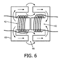
1次側巻線が電力送信アンテナとして機能する図5の実施形態に基づいて、十分な漏れ磁束を提供するために、図6に示されるような実施形態が変圧器64用の改良された磁気コア60を提供する。1次側巻線42、及び62として示される2次側巻線がコア60に巻き付けられており、コアは内側で磁気的に伝導性であり、外側で空隙66を有する。コアは、2つのE字型の半コアを対向するように互いに取り付けることにより形成されることができ、E字型コアの中部の脚が側部の脚よりも長くなっている。図6中の矢印は、磁束を概略的に示している。
In order to provide sufficient leakage flux based on the embodiment of FIG. 5 where the primary winding functions as a power transmitting antenna, an embodiment such as that shown in FIG. A
図7は、図6の変圧器の磁気抵抗回路図を示す。変圧器のコアにおける空隙が磁気回路の磁気抵抗を増加させ、コアが飽和する前に磁気回路がより多くのエネルギーを蓄積することを可能にする。磁気抵抗は電気回路における抵抗に類似しているが、電気エネルギーを放散するよりも、むしろ磁気エネルギーを蓄積する。電界が電流に最も抵抗の少ない経路をたどらせるように、磁界が磁束に最も磁気抵抗の少ない経路をたどらせる。R2及びR3が提案された変圧器の2つの空隙を表している。φ1は、変圧器の1次巻線によって生成される磁界の磁束である。この新規の変圧器について、磁気エネルギーはR2とR3との間に分散され、φ2とφ3との合計はφ1に等しいはずである。 FIG. 7 shows a magnetoresistive circuit diagram of the transformer of FIG. The air gap in the transformer core increases the reluctance of the magnetic circuit, allowing the magnetic circuit to store more energy before the core is saturated. Magnetoresistance is similar to resistance in electrical circuits, but stores magnetic energy rather than dissipating electrical energy. Just as the electric field follows the path of least resistance to current, the magnetic field causes the path of flux to follow the path of least resistance. R 2 and R 3 represent the two air gaps of the proposed transformer. φ 1 is the magnetic flux of the magnetic field generated by the primary winding of the transformer. This new transformers, magnetic energy is distributed between the R 2 and R 3, the sum of phi 2 and phi 3 should be equal to phi 1.
図8は、前述の第2のコイル44が巻き付けられている追加のコア80が、コア60に結合されるやり方を示している。空隙を有するコア60の外側が、前述の第2のコイル44が巻かれている追加のコア80を結合するように適合されている。追加の巻線(C字型コア)は変圧器の十分に近くに配置されているので、この巻線は余分な2次巻線として作用して変圧器の1次巻線に結合される。追加の巻線の負荷として、センサが変圧器から無線でエネルギーを取得することができる。
FIG. 8 shows how an
図9は、図8の変圧器構成の磁気抵抗回路図を示す。EEコアの両側脚経路上の2つの空隙(R2及びR3)、及びEEコアと結合されたCコアとの間に新規に生成された2つの空隙(即ち、R4)の存在のおかげで、磁束が各経路の磁気抵抗に依存して再分配される。φ1は依然として、1次巻線によって生成される磁界の磁束である。R4−R4の経路は、R2及びR3の経路に対して並列回路として作用する。磁気エネルギーはR2、R3、及びR4の間で再分配され、φ2、φ3、及びφ4の合計はφ1に等しい。 FIG. 9 shows a magnetoresistive circuit diagram of the transformer configuration of FIG. Thanks to the presence of two voids (R 2 and R 3 ) on the bilateral leg path of the EE core and two newly created voids (ie, R 4 ) between the EE core and the combined C core Thus, the magnetic flux is redistributed depending on the magnetoresistance of each path. φ 1 is still the magnetic flux generated by the primary winding. The path R 4 -R 4 acts as a parallel circuit for the paths R 2 and R 3 . Magnetic energy is redistributed between R 2 , R 3 , and R 4 , and the sum of φ 2 , φ 3 , and φ 4 is equal to φ 1 .
C字型コアを通って流れる磁束の量が、センサに伝送されるエネルギーの量を決定する。これは、EEコアとCコアとの間の2つの空隙の大きさを変更することによって、調節され得る。空隙が大きくなることは、経路上の磁気抵抗(即ち、R4)がより大きくなることを意味し、通って流れる磁束がより少なくなることにつながり、従って、より少ない電力が伝送され得る。 The amount of magnetic flux flowing through the C-shaped core determines the amount of energy transmitted to the sensor. This can be adjusted by changing the size of the two gaps between the EE core and the C core. Increasing the air gap means that the reluctance (ie, R 4 ) on the path is greater, leading to less magnetic flux flowing through, and thus less power can be transmitted.
変圧器と外部コアとの間の空隙は、エネルギー伝送を可能にするのに十分小さくなくてはならないことに留意しなくてはならない。大きな空隙に起因するあまりに大きな磁気抵抗は、外部コアへの磁束の流れを遮断するであろう。実際の用途では、照明器具及びセンサのケーシングが、磁束を遮断するのに十分な大きさである2mmに容易に達することができる。これは、図10に示すように、変圧器と外部コアとの間の許容される距離を拡張するために、ケーシング中に磁性材料100を埋め込むことにより、解決されることができる。異なる透磁率の材料を使用することにより、空隙の大きさを調節するのと同じ効果が得られる。
It should be noted that the air gap between the transformer and the outer core must be small enough to allow energy transfer. Too much magnetoresistance due to large air gaps will block the flow of magnetic flux to the outer core. In practical applications, the luminaire and sensor casing can easily reach 2 mm, which is large enough to block the magnetic flux. This can be solved by embedding
図4に示されるようなフライバックコンバータに戻ると、1次側巻線64aの両端の、ダイオード及び抵抗器とコンデンサの並列は、電力スイッチがオフになるときに1次側巻線中でエネルギーをフリーホイールするループである。このループは、スナバとしても知られている。本発明の実施形態は、エネルギーを節約するために、誘導電力伝送のためにフリーホイールされたエネルギーを利用することを提案する。 Returning to the flyback converter as shown in FIG. 4, the diode and resistor-capacitor parallel across the primary winding 64a are energized in the primary winding when the power switch is turned off. Is a freewheeling loop. This loop is also known as snubber. Embodiments of the present invention propose to utilize freewheeled energy for inductive power transfer to conserve energy.
照明器具11及び誘導電力受信デバイスの実施形態が図11に示されており、この照明器具は第1の電力送信アンテナLsを有するドライバを含み、この誘導電力受信デイバスは第2の電力受信アンテナRxを含む。電力送信アンテナLsはフリーホイールループ内にあり、スナバ抵抗器Rsと並列でありかつ択一的である。
An embodiment of a
フライバックコンバータの内部モジュール又は照明器具の別のモジュールであり得るリレーコントローラ114が、照明器具に取り付けられた外部デバイスの存在を監視し続け、それに応じてリレースイッチSWsを制御する。通常、リレースイッチSWsは、フリーホイールされたエネルギーを1次側巻線内でスナバするように、外部デバイスが取り付けられていないときには、抵抗器をスナバ回路に接続する。外部の誘導電力受信デバイス12が図11に示されるように照明器具(のケーシング)上に機械的に取り付けられると、リレーコントローラ114がこれを検出し、リレースイッチSWsを制御してインダクタLsをスナバに接続する。様々な方法が、機械的な構造を使用するなどして、センサを検出するために使用され得る。外部の誘導電力受信デバイス12は、無線電力受信機モジュールを含み、そのモジュールの第2の電力受信アンテナ、即ちコイルRxは、スナバ回路のインダクタLsと結合されている。誘導電力受信デバイス12は更に、負荷124に給電するために受信された電力を適切な特性に変換する、整流及び電圧/電流補正部122を含むことができる。
A
ツェナーダイオードZsが、ダイオードDs及びアンテナLs/抵抗器Rsと直列に接続されて2次側から反射される逆電圧を遮断し、その結果、フリーホイールされた電力のみがコンデンサCsに流れることが可能になる。 A zener diode Zs is connected in series with the diode Ds and the antenna Ls / resistor Rs to block the reverse voltage reflected from the secondary side, so that only freewheeled power can flow to the capacitor Cs. become.
コンデンサCsは更に、交流電流がインダクタLs上で発生し電力が伝送されるように、インダクタLsと共振することができる。 Capacitor Cs can further resonate with inductor Ls such that an alternating current is generated on inductor Ls and power is transmitted.
上記の抵抗器Rs,リレースイッチSWs、及びリレーコントローラ114は、フリーホイールされたエネルギーの全てが直接的に伝送され得るように分散されることが可能であることが、理解されるべきである。
It should be understood that the resistor Rs, relay switch SWs, and
上記の実施形態では、第1の電力送信アンテナが1次側に位置している。以下の実施形態は、2次側にある第1の電力送信アンテナを提供する。 In the above embodiment, the first power transmission antenna is located on the primary side. The following embodiments provide a first power transmission antenna on the secondary side.
図12は、ドライバ及び外部の電力受信デバイス12を有する照明器具を示す。図12に示すように、第1の電力送信アンテナ42の第1のコイルが、2次側巻線64bの出力端子に結合され、かつ、2次側巻線64bから提供される電力を受け取るように適合されている。
FIG. 12 shows a luminaire having a driver and an external
図12に示すように、ドライバは以下を含む、即ち、前述の第1のコイル42と直列の少なくとも1つの追加のコイルL2と、少なくとも1つの短絡スイッチSWであって、その各々が前述の少なくとも1つの追加のコイルL2のそれぞれと並列になっている少なくとも1つの短絡スイッチSWと、前述の短絡スイッチSWに結合された制御回路であって、2次側巻線64bによって出力される電力と、第2の電力受信アンテナ44に送信されることが必要な電力とに従って、前述のスイッチを制御してそれぞれの追加のコイルL2を短絡するための制御回路と、を含む。
As shown in FIG. 12, the driver includes: at least one additional coil L2 in series with the aforementioned
MOSFETスイッチが閉じられると、1次側巻線64aが入力電圧源、即ち入力コンデンサに接続される。1次側巻線中の電流及び変圧器中の磁束が増加し、変圧器にエネルギーを蓄積する。2次巻線64b、並びにインダクタ42及びL2が閉回路を形成する。2次巻線に誘起される電圧は(2次側巻線64bの上部端子において)負であるので、整流ダイオードは逆バイアスされる。この負の電圧は、巻線64b、接地、インダクタL2、及び電力送信42からなる閉回路中に負の電流を生成し、インダクタL2及び42にエネルギーを蓄積する。MOSFETスイッチが開かれると、1次側巻線64aの電流が停止される。2次側巻線64bの電圧が反転して(上部端子において)正になり、整流ダイオードを順方向バイアスし、電流が2次巻線から整流ダイオードに流れるのを可能にする。一方、インダクタL2及び42から整流ダイオードに流れる電流がある。変圧器コア及び2つのインダクタの両方からのエネルギーが出力コンデンサを充電し負荷に供給する。上記の2つの動作を通じて、第2の電力受信アンテナ44が、その第2のコイル44が第1の電力送信アンテナ42に結合された状態で照明器具に取り付けられる場合、アンテナ42から第2のコイル44への無線電力送信が起こるであろう。インダクタ42及びL2は、MOSFETスイッチが閉じている間にエネルギーを蓄積するための変圧器の出力であり、MOSFETスイッチが開かれるとエネルギーを負荷へ放出する。これらのインダクタを追加しても、フライバックコンバータの通常の動作には影響を与えない。
When the MOSFET switch is closed, the primary winding 64a is connected to the input voltage source, ie, the input capacitor. The current in the primary winding and the magnetic flux in the transformer increase and store energy in the transformer. The secondary winding 64b and the
代替の実施形態では、第1の電力送信アンテナは、2次側巻線の出力端子の代わりに、フライバックコンバータの出力に結合されることができる。この場合、電力送信アンテナ42は、LED照明器具のLED負荷と並列な別の負荷としてみなされ得る。接続が、整流ダイオードのアノード側にある、図12における鎖線によって示されることができる。
In an alternative embodiment, the first power transmission antenna can be coupled to the output of the flyback converter instead of the output terminal of the secondary winding. In this case, the
上記の実施形態では、電力送信アンテナ42の電力は、ドライバが2次側に提供する電力量に依存する。ドライバは通常、LEDの負荷要求に従って制御され、負荷要求が電力送信アンテナ42に伝送されることが必要な電力と一致していない場合、外部デバイス12が適切に給電されないことがある。この問題に対処するために、実施形態は、インダクタL2、スイッチSW、並びに、抵抗器Rsense、増幅器OP−AMP、及びコンパレータCOMPを含む制御回路を使用する。
In the above embodiment, the power of the
制御回路は、抵抗器Rsenseの電流を測定し、増幅し、かつ予め設定された基準値REFと比較することにより、LED負荷の電力要求を監視し続ける。LED負荷からの電力要求が特定のレベルより低く、インダクタ42のエネルギーが、取り付けられた外部デイバスに無線で給電するのに十分ではないことを導くときには、より多くのエネルギーがインダクタ42に割り当てられるように、制御回路のスイッチが閉じられてインダクタL2を短絡する。このやり方で、より多くのエネルギーが、外部デバイスに無線で送信するために利用可能になる。インダクタL2のインダクタンスがアンテナ42のN倍である場合、スイッチを閉じることがN倍のより多くのエネルギーをアンテナ42にもたらす。
The control circuit continues to monitor the power demand of the LED load by measuring the current of resistor R sense , amplifying and comparing it with a preset reference value REF. More energy will be allocated to
或いは、外部デイバスが、その内部電池を充電するため又は過度に電力を消費する動作を行うためなどに、短期の大電力を必要とする場合には、より多くのエネルギーがインダクタ42に割り当てられるように、制御回路のスイッチが閉じられてインダクタL2を短絡する。
Alternatively, more energy may be allocated to the
インダクタ42及びL2のインダクタンスは、出力電力などの、フライバックコンバータのパラメータに基づいて選択されて、コンバータがその出力電力のフルで動作しているときにこれら2つのインダクタが飽和しないように、2つのインダクタ間に適切にエネルギーを割り当てる。
The inductances of
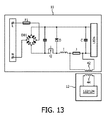
本発明の実施形態は、他の種類のコンバータにも適用されることができる。図13は、バックコンバータが第1の電力送信アンテナ42と一体化されている例を示す。図13に詳細に示されるように、第1の電力送信アンテナ42は、バックコンバータの既存のパワーインダクタ/コイルIと直列になっている。ジャンパーJは電力送信アンテナ42と並列に配置されて、電力送信が必要ない場合には、ジャンパーJは電力送信アンテナ42を短絡するためにかつバックループを形成するために使用される。電力送信アンテナ42は、パワーインダクタIの電力蓄積段階及び電力放出段階の何れか又は両方において、電力を受け取ることができる。
Embodiments of the invention can be applied to other types of converters. FIG. 13 shows an example in which the buck converter is integrated with the first
第1の例として、センサは、Texas Instruments社のLM20(商標)などの低電力温度センサであり得る。受動センサがインテリジェント照明ユニットに取り付けられているとき、このセンサはNFCインターフェースを介して通信して温度情報を提供することができる。照明ユニット内のコントローラがNFCリーダーを介して受動センサにリクエストを送信する。リクエストが受動センサによってそのNFCインターフェースを介して受信されると、受動センサ内のNFCタグがその有線のインターフェースを介してセンサコントローラにリクエストを転送する。 As a first example, the sensor may be a low power temperature sensor such as Texas Instruments LM20 ™. When a passive sensor is attached to the intelligent lighting unit, it can communicate via an NFC interface to provide temperature information. A controller in the lighting unit sends a request to the passive sensor via the NFC reader. When a request is received by the passive sensor via its NFC interface, the NFC tag in the passive sensor forwards the request to the sensor controller via its wired interface.
リクエストが受動センサのセンサコントローラによって受信されると、温度データが感知モジュールから抽出され、これはNFCタグ30のメモリユニット(例えば、EEPROM)に有線インターフェースを介して書き込まれる。
When the request is received by the sensor controller of the passive sensor, temperature data is extracted from the sensing module and written to the memory unit (eg, EEPROM) of the
NFCタグ30はそのメモリユニットに保存されたデータを、NFCインターフェースを介して、照明ユニットのNFCリーダー22に返信する。
The
第2の例として、センサは、Philips社(商標)の「OccuSwitch」(商標)などの、充電式電池給電式占有センサであり得る。センサがインテリジェント照明ユニットに取り付けられると、エネルギー効率の高い照明制御が達成される。 As a second example, the sensor may be a rechargeable battery powered occupancy sensor, such as Philips ™ “OccuSwitch” ™. When the sensor is attached to the intelligent lighting unit, energy efficient lighting control is achieved.
センサの無線電力受信機50が、電池の充電を管理する。電池を充電する必要がある(例えば、電池のエネルギーレベルが閾値未満である)とき、それは無線電力送信機40と通信して無線電力送信を開始する。
The sensor's
センサの感知モジュールが特定のエリアでの活動を監視し続け、状態(即ち、占有されているか、又は空であるか)をセンサコントローラ36に送信し、次いでセンサコントローラ36は有線のインターフェースを介して状態をNFCタグ30のメモリユニットに書き込む。
The sensor's sensing module continues to monitor activity in a particular area and sends the status (ie, occupied or empty) to the
照明ユニットのコントローラ18が、NFCリーダー22を介して活動の状態を定期的に読み出し、NFCリーダー22はNFCインターフェースを介してセンサのNFCタグ30と通信する。活動の状態に基づいて、光源コントローラ18が光源をオン及びオフにする。
The
上記の例から明らかなように、光センサ又は近接センサなどの外部センサは、光に関する状態を感知することができる。しかしながら、外部センサはまた、温度などの、環境制御の他の態様に関連する状態も感知することができる。例えば、照明システムは、照明に限らないインテリジェントな感知及び制御を提供するシステムインフラストラクチャー全体の一部であり得る。照明システムは、中央システムに報告し、その中央システムから支持を受け取る、より大きなネットワークの一部であり得る。 As is apparent from the above example, an external sensor such as a light sensor or a proximity sensor can sense a condition relating to light. However, external sensors can also sense conditions related to other aspects of environmental control, such as temperature. For example, the lighting system can be part of an overall system infrastructure that provides intelligent sensing and control that is not limited to lighting. The lighting system can be part of a larger network that reports to and receives support from the central system.
照明システムにセンサを結合することに加えて、他のデバイスが、単にそれらを充電する目的で結合されることができる。従って、ハウジングの接触界面は充電ドッキングステーションとして機能することができる。 In addition to coupling sensors to the lighting system, other devices can be coupled simply for the purpose of charging them. Thus, the contact interface of the housing can function as a charging docking station.
開示された実施形態への他の変形例が、図面、明細、及び添付の請求項の研究から、特許請求された本発明を実施する際に当業者によって理解され実施されることができる。請求項において、単語「含む(comprising)」は他の構成要素又はステップを排除するものではなく、不定冠詞「1つの(a)」又は「1つの(an)」は、複数を排除するものではない。特定の処置が互いに異なる従属請求項に記載されているという単なる事実は、これらの処置の組み合わせが利益を得るように使用され得ないということを示すものではない。請求項における任意の参照符号は、範囲を限定するものとして解釈されるべきではない。 Other variations to the disclosed embodiments can be understood and implemented by those skilled in the art in practicing the claimed invention, from a study of the drawings, specification, and appended claims. In the claims, the word “comprising” does not exclude other elements or steps, and the indefinite article “a” or “an” does not exclude a plurality. Absent. The mere fact that certain measures are recited in mutually different dependent claims does not indicate that a combination of these measures cannot be used to benefit. Any reference signs in the claims should not be construed as limiting the scope.
Claims (12)
前記ドライバが更に、
前記スイッチモード電源の前記既存のコイルであるか、又は前記スイッチモード電源の前記既存のコイルに結合されている、第1のコイルとして形成される、第1の電力送信アンテナを含み、
前記第1の電力送信アンテナが、前記ドライバの外部にあり前記負荷とは異なる第2の電力受信アンテナに磁気的に結合されて無線電力送信機を形成しており、
前記スイッチモード電源が、1次側巻線及び2次側巻線を有する変圧器を含むフライバックコンバータを含み、前記2次側巻線が前記負荷に電気的に接続され、
前記第1のコイルが前記1次側巻線と並列になっており、前記第2の電力受信アンテナが前記第1のコイルと磁気的に結合される第2のコイルを含む、ドライバ。 A driver including a switch mode power supply electrically coupled to a load and supplying power to the load, wherein the switch mode power supply includes an existing coil, and the existing coil is a power inductor of the switch mode power supply The power inductor has a passive freewheel period and an active power supply period to supply power to the load;
The driver further includes:
A first power transmitting antenna formed as a first coil that is the existing coil of the switch mode power supply or coupled to the existing coil of the switch mode power supply;
The first power transmitting antenna is externally coupled to the second power receiving antenna outside the driver and different from the load to form a wireless power transmitter ;
The switch mode power supply includes a flyback converter including a transformer having a primary winding and a secondary winding, and the secondary winding is electrically connected to the load;
The driver , wherein the first coil is in parallel with the primary winding, and the second power receiving antenna includes a second coil that is magnetically coupled to the first coil .
前記ドライバが更に、 The driver further includes:
前記スイッチモード電源の前記既存のコイルであるか、又は前記スイッチモード電源の前記既存のコイルに結合されている、第1のコイルとして形成される、第1の電力送信アンテナを含み、 A first power transmitting antenna formed as a first coil that is the existing coil of the switch mode power supply or coupled to the existing coil of the switch mode power supply;
前記第1の電力送信アンテナが、前記ドライバの外部にあり前記負荷とは異なる第2の電力受信アンテナに磁気的に結合されて無線電力送信機を形成しており、 The first power transmitting antenna is externally coupled to the second power receiving antenna outside the driver and different from the load to form a wireless power transmitter;
前記スイッチモード電源が、1次側巻線及び2次側巻線を有する変圧器を含むフライバックコンバータを含み、前記2次側巻線が前記負荷に電気的に接続され、 The switch mode power supply includes a flyback converter including a transformer having a primary winding and a secondary winding, and the secondary winding is electrically connected to the load;
前記第1の電力送信アンテナが前記1次側巻線を含み、前記第2の電力受信アンテナが、前記1次側巻線の漏れ磁束を受け取るように前記1次側巻線と離間したコイルを含む、ドライバ。 The first power transmitting antenna includes the primary winding, and the second power receiving antenna includes a coil spaced from the primary winding so as to receive the leakage flux of the primary winding. Including the driver.
前記ドライバが更に、 The driver further includes:
前記スイッチモード電源の前記既存のコイルであるか、又は前記スイッチモード電源の前記既存のコイルに結合されている、第1のコイルとして形成される、第1の電力送信アンテナを含み、 A first power transmitting antenna formed as a first coil that is the existing coil of the switch mode power supply or coupled to the existing coil of the switch mode power supply;
前記第1の電力送信アンテナが、前記ドライバの外部にあり前記負荷とは異なる第2の電力受信アンテナに磁気的に結合されて無線電力送信機を形成しており、 The first power transmitting antenna is externally coupled to the second power receiving antenna outside the driver and different from the load to form a wireless power transmitter;
前記スイッチモード電源が、1次側巻線及び2次側巻線を有する変圧器を含むフライバックコンバータを含み、前記2次側巻線が前記負荷に電気的に接続され、 The switch mode power supply includes a flyback converter including a transformer having a primary winding and a secondary winding, and the secondary winding is electrically connected to the load;
前記第1の電力送信アンテナの前記第1のコイルが、前記2次側巻線の出力端子に結合され、かつ、前記2次側巻線によって提供される電力を受け取り、 The first coil of the first power transmitting antenna is coupled to an output terminal of the secondary winding and receives power provided by the secondary winding;
前記ドライバが更に、 The driver further includes:
前記第1のコイルと直列の、少なくとも1つの追加のコイルと、 At least one additional coil in series with the first coil;
少なくとも1つの短絡スイッチであって、前記少なくとも1つの短絡スイッチの各々が前記少なくとも1つの追加のコイルのそれぞれと並列である、少なくとも1つの短絡スイッチと、 At least one short-circuit switch, wherein each of the at least one short-circuit switch is in parallel with each of the at least one additional coil;
前記短絡スイッチに結合される制御回路であって、前記2次側巻線によって出力される電力、及び前記第2の電力受信アンテナに送信されることが必要な電力に従って、前記スイッチを制御してそれぞれの前記追加のコイルを短絡するための制御回路と、を含む、ドライバ。 A control circuit coupled to the shorting switch for controlling the switch according to the power output by the secondary winding and the power required to be transmitted to the second power receiving antenna; A control circuit for short-circuiting each said additional coil.
前記ドライバが更に、 The driver further includes:
前記スイッチモード電源の前記既存のコイルであるか、又は前記スイッチモード電源の前記既存のコイルに結合されている、第1のコイルとして形成される、第1の電力送信アンテナを含み、 A first power transmitting antenna formed as a first coil that is the existing coil of the switch mode power supply or coupled to the existing coil of the switch mode power supply;
前記第1の電力送信アンテナが、前記ドライバの外部にあり前記負荷とは異なる第2の電力受信アンテナに磁気的に結合されて無線電力送信機を形成しており、 The first power transmitting antenna is externally coupled to the second power receiving antenna outside the driver and different from the load to form a wireless power transmitter;
前記スイッチモード電源が、1次側巻線及び2次側巻線を有する変圧器を含むフライバックコンバータを含み、前記2次側巻線が前記負荷に電気的に接続され、 The switch mode power supply includes a flyback converter including a transformer having a primary winding and a secondary winding, and the secondary winding is electrically connected to the load;
前記第1の電力送信アンテナの前記第1のコイルが、前記フライバックコンバータの出力端子に結合されており、 The first coil of the first power transmitting antenna is coupled to an output terminal of the flyback converter;
前記ドライバが更に、 The driver further includes:
前記第1のコイルと直列の、少なくとも1つの追加のコイルと、 At least one additional coil in series with the first coil;
少なくとも1つの短絡スイッチであって、前記少なくとも1つの短絡スイッチの各々が前記少なくとも1つの追加のコイルのそれぞれと並列である、少なくとも1つの短絡スイッチと、 At least one short-circuit switch, wherein each of the at least one short-circuit switch is in parallel with each of the at least one additional coil;
前記短絡スイッチに結合される制御回路であって、前記2次側巻線によって出力される電力、及び前記第2の電力受信アンテナに送信されることが必要な電力に従って、前記スイッチを制御してそれぞれの前記追加のコイルを短絡するための制御回路と、を含む、ドライバ。 A control circuit coupled to the shorting switch for controlling the switch according to the power output by the secondary winding and the power required to be transmitted to the second power receiving antenna; A control circuit for short-circuiting each said additional coil.
前記2次側巻線によって提供される電力を感知する感知素子を含み、
前記制御回路が、
前記2次側巻線によって提供される感知された電力が限界値未満である場合に、前記少なくとも1つの追加のコイルを短絡するか、又は、
送信されることが必要な電力が閾値を超えている場合に、前記少なくとも1つの追加のコイルを短絡する、請求項4又は5に記載のドライバ。 The control circuit further comprises:
A sensing element for sensing the power provided by the secondary winding;
The control circuit comprises:
Shorting the at least one additional coil if the sensed power provided by the secondary winding is below a limit value, or
6. A driver as claimed in claim 4 or 5 , wherein the at least one additional coil is short-circuited when the power that needs to be transmitted exceeds a threshold.
前記ドライバが更に、 The driver further includes:
前記スイッチモード電源の前記既存のコイルであるか、又は前記スイッチモード電源の前記既存のコイルに結合されている、第1のコイルとして形成される、第1の電力送信アンテナを含み、 A first power transmitting antenna formed as a first coil that is the existing coil of the switch mode power supply or coupled to the existing coil of the switch mode power supply;
前記第1の電力送信アンテナが、前記ドライバの外部にあり前記負荷とは異なる第2の電力受信アンテナに磁気的に結合されて無線電力送信機を形成しており、 The first power transmitting antenna is externally coupled to the second power receiving antenna outside the driver and different from the load to form a wireless power transmitter;
前記スイッチモード電源が、1次側巻線及び2次側巻線を有する変圧器を含むフライバックコンバータを含み、前記2次側巻線が前記負荷に電気的に接続され、 The switch mode power supply includes a flyback converter including a transformer having a primary winding and a secondary winding, and the secondary winding is electrically connected to the load;
前記フライバックコンバータが更に、 The flyback converter further includes:
前記1次側巻線の両端に結合されたフリーホイールループを含み、前記フリーホイールループが前記1次側巻線におけるエネルギーをフリーホイールし、 A freewheel loop coupled to both ends of the primary winding, the freewheel loop freewheeling energy in the primary winding;
前記第1の電力送信アンテナの前記第1のコイルが前記フリーホイールループ内にあり、 The first coil of the first power transmitting antenna is in the freewheel loop;
前記フリーホイールループが、 The freewheel loop is
前記1次側巻線の電流流出端から順方向のダイオードと、 A forward diode from the current outflow end of the primary winding;
前記1次側巻線の電流流入端と前記ダイオードとの間のコンデンサと、を含み、 A capacitor between the current inflow end of the primary winding and the diode;
前記第1のコイルが前記コンデンサと並列になっている、ドライバ。 The driver, wherein the first coil is in parallel with the capacitor.
前記コンデンサ及び前記第1のコイルと並列な抵抗器と、
前記フリーホイールループに前記第1のコイルか又は前記抵抗器の何れかを選択的に切り替えるスイッチとを含む、請求項7に記載のドライバ。 The freewheel loop further
A resistor in parallel with the capacitor and the first coil;
The driver according to claim 7 , further comprising a switch that selectively switches either the first coil or the resistor to the freewheel loop.
前記受動のフリーホイール期間中に、前記パワーインダクタが充電された電力を前記負荷に放電/放出する、請求項1乃至8のいずれか一項に記載のドライバ。 During the active feeding period, the switch mode power supply feeds / charges the power inductor;
During said passive freewheel period, the power inductor discharges / releases the power charged in the load, according to any one of claims 1 to 8 drivers.
センサとを含み、
前記センサが前記第2の電力受信アンテナを含む、センサシステム。 A lighting fixture according to claim 11 ;
Including a sensor,
A sensor system, wherein the sensor includes the second power receiving antenna.
Applications Claiming Priority (5)
| Application Number | Priority Date | Filing Date | Title |
|---|---|---|---|
| CN2014000445 | 2014-04-25 | ||
| CNPCT/CN2014/000445 | 2014-04-25 | ||
| EP14172294.2 | 2014-06-13 | ||
| EP14172294 | 2014-06-13 | ||
| PCT/EP2015/058489 WO2015162081A2 (en) | 2014-04-25 | 2015-04-20 | Switched mode power supply driver integrated with a power transmission antenna |
Publications (3)
| Publication Number | Publication Date |
|---|---|
| JP2017520218A JP2017520218A (en) | 2017-07-20 |
| JP2017520218A5 JP2017520218A5 (en) | 2018-06-07 |
| JP6605499B2 true JP6605499B2 (en) | 2019-11-13 |
Family
ID=52875714
Family Applications (1)
| Application Number | Title | Priority Date | Filing Date |
|---|---|---|---|
| JP2016563819A Active JP6605499B2 (en) | 2014-04-25 | 2015-04-20 | Switch mode power supply driver integrated with power transmission antenna |
Country Status (6)
| Country | Link |
|---|---|
| US (2) | US9814108B2 (en) |
| EP (1) | EP3135078A2 (en) |
| JP (1) | JP6605499B2 (en) |
| CN (1) | CN106464017B (en) |
| RU (1) | RU2706423C2 (en) |
| WO (1) | WO2015162081A2 (en) |
Families Citing this family (34)
| Publication number | Priority date | Publication date | Assignee | Title |
|---|---|---|---|---|
| EP2053546A1 (en) * | 2007-10-26 | 2009-04-29 | Gemplus | Radiofrequency communication device comprising a timer |
| CN107210123A (en) * | 2014-08-07 | 2017-09-26 | 达特茅斯学院托管理事会 | Magnetic devices including low AC resistance paper tinsel winding and Gapped magnet core |
| US20160057838A1 (en) * | 2014-08-25 | 2016-02-25 | General Electric Company | Extension interface for luminaires |
| EP3326238A1 (en) * | 2015-07-17 | 2018-05-30 | Philips Lighting Holding B.V. | Device with an antenna. |
| US10306715B2 (en) * | 2015-08-31 | 2019-05-28 | Tridonic Gmbh & Co Kg | Assembly with control gear for lamps |
| CN110769549B (en) * | 2015-11-06 | 2021-08-13 | 南京矽力微电子技术有限公司 | Wireless LED driving system |
| EP3193140A1 (en) * | 2016-01-15 | 2017-07-19 | Thomson Licensing | Method and apparatus for switch on/off impulse detection |
| ES2800157T3 (en) | 2016-03-04 | 2020-12-28 | Signify Holding Bv | A control system for controlling a lighting device arranged to provide functional and / or ambient lighting using the presence of a portable device |
| US10377255B2 (en) * | 2016-05-13 | 2019-08-13 | Witricity Corporation | Methods and apparatus for reducing flux cancellation in ferrite of double couple inductive power transfer systems |
| EP3466204B1 (en) * | 2016-05-30 | 2021-07-07 | Signify Holding B.V. | Switched mode power supply identification |
| JP2017221073A (en) * | 2016-06-10 | 2017-12-14 | Ntn株式会社 | Dc/dc converter |
| WO2018001785A1 (en) * | 2016-06-30 | 2018-01-04 | Philips Lighting Holding B.V. | Lighting device and power distribution |
| JP6801370B2 (en) * | 2016-10-28 | 2020-12-16 | 富士通株式会社 | Sensor device |
| US10687404B2 (en) * | 2016-10-28 | 2020-06-16 | Signify Holding B.V. | Communication interface and arrangement |
| WO2018097755A1 (en) * | 2016-11-22 | 2018-05-31 | Егор Евгеньевич НИЛОВ | Lighting device |
| US10043124B2 (en) * | 2016-12-15 | 2018-08-07 | Em Microelectronic-Marin Sa | Voltage regulation circuit for an RFID circuit |
| US10008948B1 (en) * | 2016-12-26 | 2018-06-26 | Nxp B.V. | Active clamp circuit for switched mode power supplies |
| CN108463033A (en) * | 2017-02-16 | 2018-08-28 | 朗德万斯公司 | Lighting system with wireless power source |
| FR3065349B1 (en) * | 2017-04-12 | 2019-05-03 | Safran Electronics & Defense | SYSTEM COMPRISING A BAY AND A REPLACEABLE MODULE ONLINE |
| EP3402060B1 (en) * | 2017-05-09 | 2019-10-02 | OSRAM GmbH | Electronic converter and related method of operating an electronic converter |
| EP3635355A1 (en) * | 2017-05-15 | 2020-04-15 | Integrated Device Technology, Inc. | Wireless powered sensor and sensor systems |
| TWI630843B (en) * | 2017-09-29 | 2018-07-21 | 營邦企業股份有限公司 | Light-on-and-control apparatus for panel lights through wireless energy and signal transmission |
| WO2019126220A1 (en) * | 2017-12-21 | 2019-06-27 | Randy Mark Cunningham | Device and method of verifying protective case usage |
| CN108808886A (en) * | 2018-01-10 | 2018-11-13 | 深圳市思坎普科技有限公司 | Transmitting equipment, wireless power supply system and the wireless lighting systems of wireless power supply system |
| JP7031357B2 (en) * | 2018-02-19 | 2022-03-08 | 三菱電機株式会社 | lighting equipment |
| US10608527B2 (en) * | 2018-06-01 | 2020-03-31 | I-Shou University | Power supply apparatus |
| CN108633142B (en) * | 2018-07-09 | 2024-04-16 | 赛尔富电子有限公司 | Dimming circuit of LED lamp |
| CN113056774A (en) * | 2018-11-29 | 2021-06-29 | 惠普发展公司,有限责任合伙企业 | Usage level based lighting adjustment for computing device enclosures |
| DE102020112139A1 (en) | 2020-05-05 | 2021-11-11 | Ledvance Gmbh | Lighting device with expandable functionality |
| CN112265890B (en) * | 2020-10-22 | 2022-06-03 | 重庆前卫无线电能传输研究院有限公司 | Wireless power-taking type elevator power supply system |
| JP2022076622A (en) * | 2020-11-10 | 2022-05-20 | パナソニックIpマネジメント株式会社 | Operating device, wiring accessories |
| WO2022189476A1 (en) * | 2021-03-10 | 2022-09-15 | Tridonic Gmbh & Co Kg | A driver for lighting means |
| US11695345B2 (en) | 2021-06-14 | 2023-07-04 | Apple Inc. | Power converter magnetic configurations |
| US11728740B2 (en) * | 2021-06-14 | 2023-08-15 | Apple Inc. | Flyback converters with improved magnetic configurations |
Family Cites Families (38)
| Publication number | Priority date | Publication date | Assignee | Title |
|---|---|---|---|---|
| DE19934767A1 (en) | 1999-07-23 | 2001-01-25 | Philips Corp Intellectual Pty | Magnetic component |
| US6473318B1 (en) | 2000-11-20 | 2002-10-29 | Koninklijke Philips Electronics N.V. | Leakage energy recovering system and method for flyback converter |
| ATE456851T1 (en) | 2001-03-02 | 2010-02-15 | Koninkl Philips Electronics Nv | INDUCTIVE COUPLING SYSTEM WITH CAPACITIVE PARALLEL COMPENSATION OF MUTUAL INDUCTANCE BETWEEN THE PRIMARY AND SECONDARY WINDINGS |
| JP2002272020A (en) | 2001-03-09 | 2002-09-20 | Sony Corp | Non-contact power transmission apparatus and non- contact charging apparatus |
| US6714428B2 (en) | 2002-03-26 | 2004-03-30 | Delta Electronics Inc. | Combined transformer-inductor device for application to DC-to-DC converter with synchronous rectifier |
| EP1547222B1 (en) | 2002-06-10 | 2018-10-03 | City University of Hong Kong | Planar inductive battery charger |
| US7148803B2 (en) | 2003-10-24 | 2006-12-12 | Symbol Technologies, Inc. | Radio frequency identification (RFID) based sensor networks |
| TWI278875B (en) | 2004-04-30 | 2007-04-11 | Hon Hai Prec Ind Co Ltd | DC transformer with output inductor integrated on the magnetic core thereof and a DC/DC converter employing the same |
| NO320439B1 (en) | 2004-04-30 | 2005-12-05 | Geir Olav Gyland | Device and method for contactless energy transfer |
| JP2007538478A (en) | 2004-05-04 | 2007-12-27 | コーニンクレッカ フィリップス エレクトロニクス エヌ ヴィ | Wireless resonant power supply device, wireless inductive power supply device, excitable load, wireless system, wireless energy transmission method |
| US7180759B2 (en) * | 2004-11-03 | 2007-02-20 | Square D Company | Push-pull inverter with snubber energy recovery |
| GB2429372B (en) * | 2005-08-16 | 2010-02-24 | Zarlink Semiconductor Ab | A pick up coil functioning as an inductive element and as an antenna, especially useful in high frequency medical in-vivo devices |
| TWI264247B (en) | 2005-09-23 | 2006-10-11 | Da-Sheng Li | Energy saving bulb integrated a RFID reader and the lighting system thereof |
| US8669716B2 (en) | 2007-08-30 | 2014-03-11 | Wireless Environment, Llc | Wireless light bulb |
| US8994276B2 (en) | 2006-03-28 | 2015-03-31 | Wireless Environment, Llc | Grid shifting system for a lighting circuit |
| US20080116847A1 (en) | 2006-09-01 | 2008-05-22 | Bio Aim Technologies Holding Ltd. | Systems and methods for wireless power transfer |
| EP2573923B1 (en) * | 2006-09-13 | 2019-04-03 | Cree, Inc. | Circuit for supplying electrical power |
| US7535734B2 (en) * | 2006-10-19 | 2009-05-19 | Heng-Yi Li | High power-factor AC/DC converter with parallel power processing |
| CN101536610B (en) | 2006-11-17 | 2013-05-01 | 皇家飞利浦电子股份有限公司 | Lighting tile and traffic control system containing lighting tile |
| JP2009089549A (en) | 2007-10-02 | 2009-04-23 | Panasonic Corp | Charger |
| RU2010138844A (en) | 2008-02-22 | 2012-03-27 | Эксесс Бизнес Груп Интернейшнл Ллс (Us) | INDUCTIVE POWER SUPPLY SYSTEM WITH REGISTRATION OF BATTERY TYPE |
| KR20110056334A (en) | 2008-09-23 | 2011-05-26 | 파우워매트 엘티디. | Combined antenna and inductive power receiver |
| CN101944851B (en) | 2009-05-07 | 2014-10-29 | 弗莱克斯电子有限责任公司 | Energy recovery snubber circuit for power converters |
| JP5510032B2 (en) * | 2009-05-14 | 2014-06-04 | 日産自動車株式会社 | Non-contact power feeding device |
| US20110058363A1 (en) | 2009-09-09 | 2011-03-10 | Anthony Fattizzi | Candle or Lighter with LED Simulated Flame and Wireless System For Same |
| JP4930563B2 (en) | 2009-09-18 | 2012-05-16 | ブラザー工業株式会社 | Combiner and communication system |
| US8381981B2 (en) | 2010-05-03 | 2013-02-26 | Redwood Systems, Inc. | Radio frequency identification of lighting fixtures |
| JP5573439B2 (en) | 2010-07-09 | 2014-08-20 | Tdk株式会社 | Wireless power supply device, light source cartridge, and wireless lighting system |
| EP2418830B1 (en) | 2010-08-13 | 2013-04-03 | Research In Motion Limited | Near-field communication (NFC) system providing plug-in device connection assistance features and related methods |
| US8502464B2 (en) * | 2011-02-18 | 2013-08-06 | Control Solutions LLC | Underwater lighting system and method |
| PL221896B1 (en) | 2011-03-23 | 2016-06-30 | Akademia Górniczo Hutnicza Im Stanisława Staszica W Krakowie | Method for reducing losses in an integrated inductive element and the integrated inductive element |
| GB2490119B (en) | 2011-04-18 | 2015-10-21 | Signplay Ltd | Lamp with communications antenna and light level sensor |
| CN103858357B (en) * | 2011-09-30 | 2016-10-05 | 皇家飞利浦有限公司 | Wireless induction type power transmission |
| US20130241699A1 (en) | 2012-03-19 | 2013-09-19 | Redwood Systems, Inc. | Device tracking with lighting system |
| KR101438910B1 (en) | 2012-10-04 | 2014-09-11 | 엘지이노텍 주식회사 | The Wired-Wireless Combined Power Transmission Apparatus and The Method using the same |
| KR20120116897A (en) | 2012-10-08 | 2012-10-23 | 롬태크 주식회사 | Controlling system using lighting device and tile sensor used thereof |
| KR101422947B1 (en) | 2012-12-11 | 2014-07-23 | 삼성전기주식회사 | Power factor correction circuit and power supply having the same |
| EP2770804B1 (en) | 2013-02-26 | 2020-07-15 | Nxp B.V. | Lighting control method, computer program product and lighting control system |
-
2015
- 2015-04-20 US US15/306,089 patent/US9814108B2/en not_active Expired - Fee Related
- 2015-04-20 EP EP15716827.9A patent/EP3135078A2/en not_active Withdrawn
- 2015-04-20 WO PCT/EP2015/058489 patent/WO2015162081A2/en active Application Filing
- 2015-04-20 CN CN201580022107.9A patent/CN106464017B/en not_active Expired - Fee Related
- 2015-04-20 RU RU2016141584A patent/RU2706423C2/en active
- 2015-04-20 JP JP2016563819A patent/JP6605499B2/en active Active
-
2017
- 2017-09-29 US US15/720,520 patent/US10624161B2/en active Active
Also Published As
| Publication number | Publication date |
|---|---|
| CN106464017A (en) | 2017-02-22 |
| RU2706423C2 (en) | 2019-11-19 |
| EP3135078A2 (en) | 2017-03-01 |
| CN106464017B (en) | 2020-05-19 |
| WO2015162081A2 (en) | 2015-10-29 |
| WO2015162081A3 (en) | 2016-09-22 |
| RU2016141584A3 (en) | 2018-12-06 |
| RU2016141584A (en) | 2018-05-25 |
| JP2017520218A (en) | 2017-07-20 |
| US9814108B2 (en) | 2017-11-07 |
| US20190261471A1 (en) | 2019-08-22 |
| US20170048937A1 (en) | 2017-02-16 |
| US10624161B2 (en) | 2020-04-14 |
Similar Documents
| Publication | Publication Date | Title |
|---|---|---|
| JP6605499B2 (en) | Switch mode power supply driver integrated with power transmission antenna | |
| KR102285941B1 (en) | System and method for power transfer | |
| CN103199633B (en) | Illumination wireless power supply system and lighting apparatus | |
| JP5921625B2 (en) | Adaptive power control for wireless charging | |
| KR101438910B1 (en) | The Wired-Wireless Combined Power Transmission Apparatus and The Method using the same | |
| CN106233560B (en) | Radio energy transmission system with radio energy transmission system charger | |
| KR20160100755A (en) | Wireless apparatus and method for transmitting power | |
| US10306715B2 (en) | Assembly with control gear for lamps | |
| CN101490772A (en) | Lighting system | |
| KR20140129918A (en) | Apparatus and method for receiving wireless power | |
| WO2008080405A1 (en) | A headset with a rechargeable battery, a base unit adapted to charge a rechargeable battery and a communications unit | |
| US10731837B2 (en) | Lighting module and method of controlling a lighting system | |
| US20190299800A1 (en) | Wireless power transmission device and wireless power transmission system | |
| KR101779747B1 (en) | Wireless apparatus and method for transmitting power | |
| US20220166251A1 (en) | Methods and arrangements for load control | |
| JP5979535B2 (en) | Non-contact power feeding system for lighting and lighting fixture using the same | |
| GB2564904A (en) | A multi-function light bulb | |
| KR101792936B1 (en) | A wireless power receiver and thereof operation method | |
| US9554427B2 (en) | Radio transmission between modules in a potential-separated LED converter | |
| KR20170044321A (en) | Wireless Power Transfer System, Wireless Power Receiver System and Operating method thereof | |
| KR20170139319A (en) | A wireless power transmitter and a wireless power receiver | |
| US20210337648A1 (en) | Multi-Protocol Luminaire System | |
| KR20160148239A (en) | Apparatus for receiving wireless power and system for transmitting wireless power | |
| JP2023060128A (en) | Lighting device, luminaire, and illumination control system | |
| KR20170105467A (en) | Method for wireless transmitting power |
Legal Events
| Date | Code | Title | Description |
|---|---|---|---|
| A521 | Request for written amendment filed |
Free format text: JAPANESE INTERMEDIATE CODE: A523 Effective date: 20180419 |
|
| A621 | Written request for application examination |
Free format text: JAPANESE INTERMEDIATE CODE: A621 Effective date: 20180419 |
|
| RD02 | Notification of acceptance of power of attorney |
Free format text: JAPANESE INTERMEDIATE CODE: A7422 Effective date: 20181213 |
|
| RD04 | Notification of resignation of power of attorney |
Free format text: JAPANESE INTERMEDIATE CODE: A7424 Effective date: 20181225 |
|
| A131 | Notification of reasons for refusal |
Free format text: JAPANESE INTERMEDIATE CODE: A131 Effective date: 20190531 |
|
| A521 | Request for written amendment filed |
Free format text: JAPANESE INTERMEDIATE CODE: A523 Effective date: 20190829 |
|
| TRDD | Decision of grant or rejection written | ||
| A01 | Written decision to grant a patent or to grant a registration (utility model) |
Free format text: JAPANESE INTERMEDIATE CODE: A01 Effective date: 20190919 |
|
| A61 | First payment of annual fees (during grant procedure) |
Free format text: JAPANESE INTERMEDIATE CODE: A61 Effective date: 20191016 |
|
| R150 | Certificate of patent or registration of utility model |
Ref document number: 6605499 Country of ref document: JP Free format text: JAPANESE INTERMEDIATE CODE: R150 |
|
| R250 | Receipt of annual fees |
Free format text: JAPANESE INTERMEDIATE CODE: R250 |