JP6604820B2 - Planetary gear reducer and drive mechanism - Google Patents
Planetary gear reducer and drive mechanism Download PDFInfo
- Publication number
- JP6604820B2 JP6604820B2 JP2015213891A JP2015213891A JP6604820B2 JP 6604820 B2 JP6604820 B2 JP 6604820B2 JP 2015213891 A JP2015213891 A JP 2015213891A JP 2015213891 A JP2015213891 A JP 2015213891A JP 6604820 B2 JP6604820 B2 JP 6604820B2
- Authority
- JP
- Japan
- Prior art keywords
- magnetic
- axial direction
- planet carrier
- gear
- planetary
- Prior art date
- Legal status (The legal status is an assumption and is not a legal conclusion. Google has not performed a legal analysis and makes no representation as to the accuracy of the status listed.)
- Expired - Fee Related
Links
Images


Classifications
-
- F—MECHANICAL ENGINEERING; LIGHTING; HEATING; WEAPONS; BLASTING
- F16—ENGINEERING ELEMENTS AND UNITS; GENERAL MEASURES FOR PRODUCING AND MAINTAINING EFFECTIVE FUNCTIONING OF MACHINES OR INSTALLATIONS; THERMAL INSULATION IN GENERAL
- F16H—GEARING
- F16H1/00—Toothed gearings for conveying rotary motion
- F16H1/28—Toothed gearings for conveying rotary motion with gears having orbital motion
- F16H1/32—Toothed gearings for conveying rotary motion with gears having orbital motion in which the central axis of the gearing lies inside the periphery of an orbital gear
-
- H—ELECTRICITY
- H02—GENERATION; CONVERSION OR DISTRIBUTION OF ELECTRIC POWER
- H02K—DYNAMO-ELECTRIC MACHINES
- H02K49/00—Dynamo-electric clutches; Dynamo-electric brakes
- H02K49/10—Dynamo-electric clutches; Dynamo-electric brakes of the permanent-magnet type
- H02K49/102—Magnetic gearings, i.e. assembly of gears, linear or rotary, by which motion is magnetically transferred without physical contact
-
- F—MECHANICAL ENGINEERING; LIGHTING; HEATING; WEAPONS; BLASTING
- F16—ENGINEERING ELEMENTS AND UNITS; GENERAL MEASURES FOR PRODUCING AND MAINTAINING EFFECTIVE FUNCTIONING OF MACHINES OR INSTALLATIONS; THERMAL INSULATION IN GENERAL
- F16H—GEARING
- F16H49/00—Other gearings
- F16H49/005—Magnetic gearings with physical contact between gears
-
- H—ELECTRICITY
- H02—GENERATION; CONVERSION OR DISTRIBUTION OF ELECTRIC POWER
- H02K—DYNAMO-ELECTRIC MACHINES
- H02K7/00—Arrangements for handling mechanical energy structurally associated with dynamo-electric machines, e.g. structural association with mechanical driving motors or auxiliary dynamo-electric machines
- H02K7/10—Structural association with clutches, brakes, gears, pulleys or mechanical starters
- H02K7/116—Structural association with clutches, brakes, gears, pulleys or mechanical starters with gears
-
- H—ELECTRICITY
- H02—GENERATION; CONVERSION OR DISTRIBUTION OF ELECTRIC POWER
- H02K—DYNAMO-ELECTRIC MACHINES
- H02K7/00—Arrangements for handling mechanical energy structurally associated with dynamo-electric machines, e.g. structural association with mechanical driving motors or auxiliary dynamo-electric machines
- H02K7/10—Structural association with clutches, brakes, gears, pulleys or mechanical starters
- H02K7/118—Structural association with clutches, brakes, gears, pulleys or mechanical starters with starting devices
- H02K7/1185—Structural association with clutches, brakes, gears, pulleys or mechanical starters with starting devices with a mechanical one-way direction control, i.e. with means for reversing the direction of rotation of the rotor
Description
本発明は、磁気式の遊星歯車減速機に関する。また、本発明は、かかる遊星歯車減速機を備える駆動機構に関する。 The present invention relates to a magnetic planetary gear reducer. The present invention also relates to a drive mechanism including such a planetary gear reducer.
従来、磁気式の遊星歯車減速機が知られている(たとえば、特許文献1参照)。特許文献1に記載の遊星歯車減速機は、磁気式歯車であるサンギアと、磁気式歯車である4個のプラネタリギアとを備えている。サンギアおよびプラネタリギアは、円筒状に形成されており、4個のプラネタリギアは、サンギアを外周側から囲むように配置されている。サンギアは、入力軸の外周面に固定され、サンギアは、回転軸の外周面に固定されている。サンギアが固定される回転軸は、プラネタリキャリアに回転可能に保持されている。4個のプラネタリギアの外周側には、円筒状のハウジングヨークが配置されている。 Conventionally, a magnetic planetary gear reducer has been known (see, for example, Patent Document 1). The planetary gear speed reducer described in Patent Document 1 includes a sun gear that is a magnetic gear and four planetary gears that are magnetic gears. The sun gear and the planetary gear are formed in a cylindrical shape, and the four planetary gears are arranged so as to surround the sun gear from the outer peripheral side. The sun gear is fixed to the outer peripheral surface of the input shaft, and the sun gear is fixed to the outer peripheral surface of the rotating shaft. The rotating shaft to which the sun gear is fixed is rotatably held by the planetary carrier. A cylindrical housing yoke is disposed on the outer peripheral side of the four planetary gears.
特許文献1に記載の遊星歯車減速機において、動力の伝達効率を高めるためには、プラネタリギアが固定される回転軸の軸方向(すなわち、サンギアが固定される入力軸の軸方向)における遊星歯車減速機の摩擦損失が小さいことが好ましい。 In the planetary gear reducer described in Patent Document 1, in order to increase the power transmission efficiency, the planetary gear in the axial direction of the rotating shaft to which the planetary gear is fixed (that is, the axial direction of the input shaft to which the sun gear is fixed). It is preferable that the friction loss of the speed reducer is small.
そこで、本発明の課題は、磁気式太陽歯車と磁気式遊星歯車とを備える磁気式の遊星歯車減速機において、磁気式遊星歯車が固定される回転軸の軸方向における摩擦損失を低減することが可能な遊星歯車減速機を提供することにある。また、本発明の課題は、かかる遊星歯車減速機を備える駆動機構を提供することにある。 Accordingly, an object of the present invention is to reduce friction loss in the axial direction of a rotating shaft to which a magnetic planetary gear is fixed in a magnetic planetary gear reducer including a magnetic sun gear and a magnetic planetary gear. It is to provide a possible planetary gear reducer. Moreover, the subject of this invention is providing the drive mechanism provided with this planetary gear speed reducer.
上記の課題を解決するため、本発明の遊星歯車減速機は、磁気式太陽歯車と、磁気式太陽歯車の周囲を自転しながら公転する複数の磁気式遊星歯車と、複数の磁気式遊星歯車を外周側から囲むように配置される磁気式内歯車と、複数の磁気式遊星歯車のそれぞれが固定される複数の回転軸と、複数の回転軸を回転可能に保持する遊星キャリアと、遊星キャリアを回転可能に保持するとともに磁気式内歯車が固定される本体部とを備え、複数の回転軸は、遊星キャリアに対して回転軸の軸方向への移動が可能となるように遊星キャリアに保持され、遊星キャリアは、本体部に対して軸方向への移動が可能となるように本体部に保持され、複数の回転軸のうちの1本の回転軸を第1回転軸とし、第1回転軸を除いた残りの回転軸のそれぞれを第2回転軸とすると、軸方向の一端側における第1回転軸と遊星キャリアとの軸方向の隙間と軸方向の他端側における第1回転軸と遊星キャリアとの軸方向の隙間との和は、軸方向の一端側における第2回転軸と遊星キャリアとの軸方向の隙間と軸方向の他端側における第2回転軸と遊星キャリアとの軸方向の隙間との和、および、軸方向の一端側における遊星キャリアと本体部との軸方向の隙間と軸方向の他端側における遊星キャリアと本体部との軸方向の隙間との和よりも小さくなっており、軸方向において第1回転軸と遊星キャリアとが接触しているときに、軸方向における両端側で、第2回転軸と遊星キャリアとの間および遊星キャリアと本体部との間に軸方向の隙間が形成されていることを特徴とする。 In order to solve the above problems, a planetary gear reducer of the present invention includes a magnetic sun gear, a plurality of magnetic planetary gears that revolve while rotating around the magnetic sun gear, and a plurality of magnetic planetary gears. A magnetic internal gear arranged so as to surround from the outer peripheral side, a plurality of rotating shafts to which each of the plurality of magnetic planetary gears is fixed, a planet carrier that rotatably holds the plurality of rotating shafts, and a planet carrier A plurality of rotating shafts held by the planetary carrier so that the rotating shaft can move in the axial direction with respect to the planetary carrier. The planetary carrier is held by the main body so as to be movable in the axial direction with respect to the main body, and one of the plurality of rotating shafts is used as the first rotating shaft, and the first rotating shaft Each of the remaining rotating shafts except for Assuming the rotation axis, the sum of the axial clearance between the first rotating shaft and the planet carrier on one end side in the axial direction and the axial clearance between the first rotating shaft and the planet carrier on the other end side in the axial direction is: Sum of the axial clearance between the second rotating shaft and the planet carrier on one end side in the axial direction and the axial clearance between the second rotating shaft and the planet carrier on the other end side in the axial direction, and one end in the axial direction Smaller than the sum of the axial clearance between the planet carrier and the main body portion on the side and the axial clearance between the planet carrier and the main body portion on the other end side in the axial direction. An axial gap is formed between the second rotating shaft and the planet carrier and between the planet carrier and the main body at both ends in the axial direction when the planet carrier is in contact with the planet carrier. And
本発明において、たとえば、軸方向における磁気式太陽歯車および磁気式内歯車の磁気中心と、軸方向における磁気式遊星歯車の磁気中心とが軸方向において一致しており、遊星キャリアに作用する軸方向の外力は、磁気式太陽歯車および磁気式内歯車と、第1回転軸に固定される磁気式遊星歯車との間に作用する軸方向の磁気的吸引力以下となっている。 In the present invention, for example, the magnetic center of the magnetic sun gear and the magnetic internal gear in the axial direction and the magnetic center of the magnetic planetary gear in the axial direction coincide in the axial direction, and the axial direction acting on the planet carrier The external force is less than or equal to the axial magnetic attractive force acting between the magnetic sun gear and the magnetic internal gear and the magnetic planetary gear fixed to the first rotating shaft.
本発明の遊星歯車減速機では、軸方向の一端側における第1回転軸と遊星キャリアとの軸方向の隙間と軸方向の他端側における第1回転軸と遊星キャリアとの軸方向の隙間との和は、軸方向の一端側における第2回転軸と遊星キャリアとの軸方向の隙間と軸方向の他端側における第2回転軸と遊星キャリアとの軸方向の隙間との和、および、軸方向の一端側における遊星キャリアと本体部との軸方向の隙間と軸方向の他端側における遊星キャリアと本体部との軸方向の隙間との和よりも小さくなっている。また、本発明では、軸方向において第1回転軸と遊星キャリアとが接触しているときに、軸方向における両端側で、第2回転軸と遊星キャリアとの間に軸方向の隙間が形成されている。そのため、本発明では、たとえば、軸方向における磁気式太陽歯車および磁気式内歯車の磁気中心と、軸方向における磁気式遊星歯車の磁気中心とが軸方向において一致していれば、1本の回転軸(第1回転軸)と遊星キャリアとの間で軸方向における摩擦損失が生じたとしても、残りの回転軸と遊星キャリアとの間では、軸方向における摩擦損失が生じない。したがって、本発明では、回転軸の軸方向における遊星歯車減速機の摩擦損失を低減することが可能になる。 In the planetary gear reducer of the present invention, the axial clearance between the first rotating shaft and the planet carrier on one end side in the axial direction, and the axial clearance between the first rotating shaft and the planet carrier on the other end side in the axial direction. Is the sum of the axial clearance between the second rotating shaft and the planet carrier on one end side in the axial direction and the axial clearance between the second rotating shaft and the planet carrier on the other end side in the axial direction, and It is smaller than the sum of the axial clearance between the planet carrier and the main body on one end side in the axial direction and the axial clearance between the planet carrier and the main body on the other end side in the axial direction. In the present invention, when the first rotating shaft and the planet carrier are in contact with each other in the axial direction, an axial gap is formed between the second rotating shaft and the planet carrier on both ends in the axial direction. ing. Therefore, in the present invention, for example, if the magnetic center of the magnetic sun gear and the magnetic internal gear in the axial direction matches the magnetic center of the magnetic planetary gear in the axial direction, one rotation is performed. Even if friction loss in the axial direction occurs between the shaft (first rotation shaft) and the planet carrier, friction loss in the axial direction does not occur between the remaining rotation shaft and the planet carrier. Therefore, in the present invention, it is possible to reduce the friction loss of the planetary gear reducer in the axial direction of the rotating shaft.
また、本発明では、軸方向において第1回転軸と遊星キャリアとが接触しているときに、軸方向における両端側で、遊星キャリアと本体部との間に軸方向の隙間が形成されている。そのため、本発明では、たとえば、軸方向における磁気式太陽歯車および磁気式内歯車の磁気中心と、軸方向における磁気式遊星歯車の磁気中心とが軸方向において一致しており、かつ、遊星キャリアに作用する軸方向の外力が、磁気式太陽歯車および磁気式内歯車と、第1回転軸に固定される磁気式遊星歯車との間に作用する軸方向の磁気的吸引力以下となっていれば、遊星キャリアと本体部とが軸方向で接触せず、遊星キャリアと本体部との間で軸方向における摩擦損失が生じない。したがって、本発明では、回転軸の軸方向における遊星歯車減速機の摩擦損失を低減することが可能になる。 In the present invention, when the first rotating shaft and the planet carrier are in contact with each other in the axial direction, an axial gap is formed between the planet carrier and the main body at both ends in the axial direction. . Therefore, in the present invention, for example, the magnetic center of the magnetic sun gear and the magnetic internal gear in the axial direction and the magnetic center of the magnetic planetary gear in the axial direction match in the axial direction, and the planet carrier If the acting axial external force is less than or equal to the axial magnetic attractive force acting between the magnetic sun gear and the magnetic internal gear and the magnetic planetary gear fixed to the first rotating shaft The planet carrier and the main body portion do not contact in the axial direction, and no friction loss occurs in the axial direction between the planet carrier and the main body portion. Therefore, in the present invention, it is possible to reduce the friction loss of the planetary gear reducer in the axial direction of the rotating shaft.
また、上記の課題を解決するため、本発明の遊星歯車減速機は、磁気式太陽歯車と、磁気式太陽歯車の周囲を自転しながら公転する複数の磁気式遊星歯車と、複数の磁気式遊星歯車を外周側から囲むように配置される磁気式内歯車と、複数の磁気式遊星歯車のそれぞれが固定される複数の回転軸と、複数の回転軸を回転可能に保持する遊星キャリアと、遊星キャリアを回転可能に保持するとともに磁気式内歯車が固定される本体部とを備え、複数の回転軸は、遊星キャリアに対して回転軸の軸方向への移動が可能となるように遊星キャリアに保持され、遊星キャリアは、本体部に対して軸方向への移動が可能となるように本体部に保持され、軸方向の一端側における遊星キャリアと本体部との軸方向の隙間と軸方向の他端側における遊星キャリアと本体部との軸方向の隙間との和は、軸方向の一端側における回転軸と遊星キャリアとの軸方向の隙間と軸方向の他端側における回転軸と遊星キャリアとの軸方向の隙間との和よりも小さくなっており、軸方向において遊星キャリアと本体部とが接触しているときに、軸方向における両端側で、回転軸と遊星キャリアとの間に軸方向の隙間が形成され、軸方向における磁気式太陽歯車および磁気式内歯車の磁気中心と、軸方向における磁気式遊星歯車の磁気中心とが軸方向において一致しており、遊星キャリアに作用する軸方向の外力は、磁気式太陽歯車および磁気式内歯車と、1個の磁気式遊星歯車との間に作用する軸方向の磁気的吸引力よりも大きくなっていることを特徴とする。 In order to solve the above problems, a planetary gear speed reducer of the present invention includes a magnetic sun gear, a plurality of magnetic planetary gears that revolve around the magnetic sun gear, and a plurality of magnetic planetary gears. A magnetic internal gear disposed so as to surround the gear from the outer peripheral side, a plurality of rotating shafts to which each of the plurality of magnetic planetary gears is fixed, a planet carrier that rotatably holds the plurality of rotating shafts, and a planet And a main body portion that holds the carrier rotatably and to which the magnetic internal gear is fixed, and the plurality of rotating shafts are arranged on the planetary carrier so that the rotating shaft can move in the axial direction with respect to the planetary carrier. The planet carrier is held by the main body so as to be movable in the axial direction relative to the main body, and the axial gap between the planet carrier and the main body at one end in the axial direction and the axial Planetary carrier at the other end The sum of the axial clearance between the main body and the main body is determined by the axial clearance between the rotating shaft and the planet carrier at one axial end and the axial clearance between the rotating shaft and the planet carrier at the other axial end. When the planetary carrier and the main body are in contact with each other in the axial direction, an axial gap is formed between the rotating shaft and the planetary carrier at both ends in the axial direction. The magnetic center of the magnetic sun gear and magnetic internal gear in the axial direction and the magnetic center of the magnetic planetary gear in the axial direction coincide with each other in the axial direction, and the axial external force acting on the planet carrier is It is characterized by being larger than the magnetic attractive force in the axial direction acting between the magnetic sun gear and the magnetic internal gear and one magnetic planetary gear .
本発明の遊星歯車減速機では、軸方向の一端側における遊星キャリアと本体部との軸方向の隙間と軸方向の他端側における遊星キャリアと本体部との軸方向の隙間との和は、軸方向の一端側における回転軸と遊星キャリアとの軸方向の隙間と軸方向の他端側における回転軸と遊星キャリアとの軸方向の隙間との和よりも小さくなっており、軸方向において遊星キャリアと本体部とが接触しているときに、軸方向における両端側で、回転軸と遊星キャリアとの間に軸方向の隙間が形成されている。そのため、本発明では、たとえば、軸方向における磁気式太陽歯車および磁気式内歯車の磁気中心と、軸方向における磁気式遊星歯車の磁気中心とが軸方向において一致していれば、本体部と遊星キャリアとの間では軸方向の摩擦損失が生じるが、複数の回転軸と遊星キャリアとの間では軸方向の摩擦損失が生じない。したがって、本発明では、回転軸の軸方向における摩擦損失を低減することが可能になる。 In the planetary gear speed reducer of the present invention, the sum of the axial clearance between the planet carrier and the main body on one end side in the axial direction and the axial clearance between the planet carrier and the main body on the other end side in the axial direction is: It is smaller than the sum of the axial clearance between the rotating shaft and the planet carrier on one end side in the axial direction and the axial clearance between the rotating shaft and the planet carrier on the other end side in the axial direction. When the carrier and the main body are in contact, an axial gap is formed between the rotating shaft and the planet carrier on both ends in the axial direction. Therefore, in the present invention, for example, if the magnetic center of the magnetic sun gear and the magnetic internal gear in the axial direction matches the magnetic center of the magnetic planetary gear in the axial direction, the main body and the planet An axial friction loss occurs between the carrier and the carrier, but no axial friction loss occurs between the plurality of rotating shafts and the planet carrier. Therefore, in the present invention, it is possible to reduce the friction loss in the axial direction of the rotating shaft.
本発明において、磁気式太陽歯車の外径と磁気式遊星歯車の外径とが等しいことが好ましい。このように構成すると、磁気式太陽歯車の外周側で隣接配置される磁気式遊星歯車同士の距離を遠ざけることが可能になり、隣接配置される磁気式遊星歯車間での磁気干渉を抑制することが可能になる。したがって、磁気式太陽歯車と磁気式遊星歯車との間の動力の伝達効率を高めることが可能になる。 In the present invention, the outer diameter of the magnetic sun gear and the outer diameter of the magnetic planetary gear are preferably equal. If comprised in this way, it will become possible to keep away the distance of the magnetic planetary gears adjacently arranged by the outer peripheral side of a magnetic sun gear, and it will suppress magnetic interference between the magnetic planetary gears adjacently arranged. Is possible. Accordingly, it is possible to increase the power transmission efficiency between the magnetic sun gear and the magnetic planetary gear.
本発明において、遊星歯車減速機は、たとえば、1個の磁気式太陽歯車と、磁気式太陽歯車を中心に90°ピッチで配置される4個の磁気式遊星歯車とを備えている。この場合には、磁気式太陽歯車と磁気式遊星歯車とは同形状に形成され、磁気式太陽歯車の外周面の磁極の数と、磁気式遊星歯車の外周面の磁極の数とが等しいことが好ましい。また、この場合には、遊星歯車減速機の減速比は1/4であることが好ましい。このように構成すると、磁気式太陽歯車と磁気式遊星歯車とを共通化できるため、遊星歯車減速機を構成する部品の種類を減らすことが可能になる。 In the present invention, the planetary gear reducer includes, for example, one magnetic sun gear and four magnetic planetary gears arranged at a pitch of 90 ° around the magnetic sun gear. In this case, the magnetic sun gear and the magnetic planetary gear are formed in the same shape, and the number of magnetic poles on the outer peripheral surface of the magnetic sun gear is equal to the number of magnetic poles on the outer peripheral surface of the magnetic planetary gear. Is preferred. In this case, the reduction ratio of the planetary gear speed reducer is preferably 1/4. If comprised in this way, since a magnetic sun gear and a magnetic planetary gear can be made shared, it will become possible to reduce the kind of components which comprise a planetary gear reducer.
本発明の遊星歯車減速機は、遊星歯車減速機の入力側に連結されるとともに磁気式太陽歯車に出力軸が連結されるモータと、遊星歯車減速機の出力側に連結される減速機とを備える駆動機構に用いることができる。この駆動機構では、遊星歯車減速機の回転軸の軸方向における摩擦損失を低減することが可能になる。また、この駆動機構では、遊星歯車減速機の磁気式太陽歯車にモータの出力軸が連結されており、回転速度が比較的速い位置に磁気式の遊星歯車減速機が配置されているため、駆動機構を静音化することが可能になる。 A planetary gear reducer according to the present invention includes a motor connected to the input side of the planetary gear reducer and an output shaft connected to the magnetic sun gear, and a reducer connected to the output side of the planetary gear reducer. It can be used for a drive mechanism provided. With this drive mechanism, it is possible to reduce friction loss in the axial direction of the rotating shaft of the planetary gear reducer. In this drive mechanism, the output shaft of the motor is connected to the magnetic sun gear of the planetary gear speed reducer, and the magnetic planetary gear speed reducer is arranged at a relatively high rotational speed. It becomes possible to silence the mechanism.
以上のように、本発明では、磁気式太陽歯車と磁気式遊星歯車とを備える磁気式の遊星歯車減速機において、磁気式遊星歯車が固定される回転軸の軸方向における摩擦損失を低減することが可能になる。また、本発明の駆動機構では、駆動機構を静音化することが可能になる。 As described above, in the present invention, in a magnetic planetary gear reducer including a magnetic sun gear and a magnetic planetary gear, friction loss in the axial direction of the rotating shaft to which the magnetic planetary gear is fixed is reduced. Is possible. In the drive mechanism of the present invention, the drive mechanism can be quieted.
以下、図面を参照しながら、本発明の実施の形態を説明する。 Hereinafter, embodiments of the present invention will be described with reference to the drawings.
(駆動ユニットの構成)
図1は、本発明の実施の形態にかかる遊星歯車減速機1を備える駆動ユニット2の側面図である。図2は、図1に示す遊星歯車減速機1の断面図である。図3は、図2に示す遊星歯車減速機1の一部の分解斜視図である。図4は、図2のE−E断面の断面図である。
(Configuration of drive unit)
FIG. 1 is a side view of a drive unit 2 including a planetary gear reducer 1 according to an embodiment of the present invention. FIG. 2 is a cross-sectional view of the planetary gear speed reducer 1 shown in FIG. FIG. 3 is an exploded perspective view of a part of the planetary gear speed reducer 1 shown in FIG. 4 is a cross-sectional view taken along the line EE of FIG.
本形態の遊星歯車減速機1(以下、「減速機1」とする)は、所定の動作対象物(図示省略)を動作させる駆動ユニット2の一部を構成している。駆動ユニット2は、減速機1の入力側に連結されるモータ3と、減速機1の出力側に連結される減速機4とを備えている。本形態では、減速機1とモータ3と減速機4とによって駆動機構5が構成されている。また、駆動ユニット2は、減速機4の出力軸に連結されるネジ部材6と、ネジ部材6に係合するナット部材7と、ナット部材7および動作対象物が固定されるスライド部材8と、スライド部材8を案内するガイド軸9とを備えている。
The planetary gear speed reducer 1 (hereinafter referred to as “speed reducer 1”) of this embodiment constitutes a part of a drive unit 2 that operates a predetermined operation target (not shown). The drive unit 2 includes a
なお、以下の説明では、図1等のZ1方向側を「前」側とし、図1等のZ2方向側を「後(後ろ)」側とする。本形態では、モータ3と減速機1と減速機4とが後ろ側から前側に向かってこの順番で配置されている。また、ネジ部材6、ナット部材7、スライド部材8およびガイド軸9は、減速機4よりも前側に配置されている。
In the following description, the Z1 direction side in FIG. 1 or the like is the “front” side, and the Z2 direction side in FIG. 1 or the like is the “rear (back)” side. In this embodiment, the
減速機1は、磁気式の遊星歯車減速機であり、円筒状の永久磁石である磁気式太陽歯車11(以下、「太陽歯車11」とする)と、円筒状の永久磁石である複数の磁気式遊星歯車12(以下、「遊星歯車12」とする)と、円筒状の永久磁石である磁気式内歯車13(以下、「内歯車13」とする)とを備えている。また、減速機1は、複数の遊星歯車12のそれぞれが固定される複数の回転軸14と、複数の回転軸14を回転可能に保持する遊星キャリア15と、遊星キャリア15を回転可能に保持するとともに内歯車13が固定される本体部16とを備えている。本形態の減速機1は、4個の遊星歯車12と、4本の回転軸14とを備えており、4本の回転軸14が遊星キャリア15に回転可能に保持されている。
The speed reducer 1 is a magnetic planetary gear speed reducer, and includes a magnetic sun gear 11 (hereinafter referred to as “
太陽歯車11は、略円筒状に形成される保持部材17の外周面に固定されている。保持部材17は、略円筒状に形成される保持部材17の軸方向と前後方向とが一致するように配置されており、保持部材17の前端側が太陽歯車11の内周側に挿入された状態で保持部材17に太陽歯車11が固定されている。保持部材17には、モータ3の出力軸3aが固定されている。具体的には、保持部材17の内周側に出力軸3aが後ろから挿入された状態で保持部材17の内周面に出力軸3aが固定されている。すなわち、太陽歯車11には、保持部材17を介してモータ3の出力軸3aが連結されている。
The
遊星歯車12は、回転軸14の外周面に固定されている。すなわち、回転軸14が遊星歯車12の内周側に挿通された状態で回転軸14に遊星歯車12が固定されている。回転軸14は、回転軸14の軸方向と前後方向とが一致するように配置されている。この回転軸14は、回転軸14の前端側部分および後端側部分の外径が回転軸14の前後方向の中間部分の外径よりも小さい段付きの細長い円柱状に形成されている。そのため、回転軸14の前端側には、前側を向く段差面14aが形成され、回転軸14の後端側には、後ろ側を向く段差面14bが形成されている。段差面14a、14bは、前後方向に直交する平面状に形成されるとともに円環状に形成されている。
The
図4に示すように、4個の遊星歯車12は、太陽歯車11を中心に90°ピッチで配置されている。また、4個の遊星歯車12は、太陽歯車11に対して同心円状に配置されており、太陽歯車11の外周面と4個の遊星歯車12のそれぞれの外周面との間には、等しい隙間が形成されている。4個の遊星歯車12は、前後方向において同じ位置に配置されており、4個の遊星歯車12の前後方向における磁気中心は、前後方向において一致している。以下、遊星歯車12の前後方向の磁気中心を「磁気中心CL1」とする。
As shown in FIG. 4, the four
本形態では、太陽歯車11の外径と遊星歯車12の外径とが等しくなっている。また、本形態では、太陽歯車11と遊星歯車12とが同形状に形成されている。すなわち、太陽歯車11の前後方向の長さと遊星歯車12の前後方向の長さとが等しくなっている。また、太陽歯車11の内径と遊星歯車12の内径とが等しくなっており、保持部材17の、太陽歯車11の内周側に挿入される部分の外径と、回転軸14の、遊星歯車12の内周側に挿入される部分の外径とが等しくなっている。さらに、本形態では、太陽歯車11の外周面に着磁される磁極の数と、遊星歯車12の外周面に着磁される磁極の数とが等しくなっている。
In this embodiment, the outer diameter of the
内歯車13は、4個の遊星歯車12を外周側から囲むように配置されている。また、内歯車13は、太陽歯車11と同軸上に配置されており、内歯車13の内周面と4個の遊星歯車12のそれぞれの外周面との間には、等しい隙間が形成されている。前後方向における内歯車13の長さは、前後方向における太陽歯車11の長さと等しくなっている。太陽歯車11と内歯車13とは、前後方向において同じ位置に配置されている。また、本形態では、前後方向における太陽歯車11の磁気中心と前後方向における内歯車13の磁気中心とが前後方向において一致している。以下、前後方向における太陽歯車11および内歯車13の磁気中心を「磁気中心CL2」とする。
The
上述のように、内歯車13は、本体部16に固定されている。そのため、太陽歯車11が回転すると、4個の遊星歯車12が遊星キャリア15に対して回転するとともに、本体部16に対して遊星キャリア15が回転する。すなわち、太陽歯車11が回転すると、4個の遊星歯車12が、太陽歯車11の周囲を自転しながら公転する。本形態では、内歯車13の内周面に着磁される磁極の数は、太陽歯車11の外周面の磁極の数の3倍となっている。そのため、本形態では、減速機1の減速比は、1/4となっている。
As described above, the
遊星キャリア15は、遊星キャリア15に対して前後方向への移動が可能となるように4本の回転軸14を保持している。この遊星キャリア15は、回転軸14の前端側の小径部分を保持する保持部材20と、回転軸14の後端側の小径部分を保持する保持部材21と、保持部材20に固定される出力軸22とを備えている。保持部材20は、略円板状に形成される端板部20aと、端板部20aから後ろ側へ突出する4個の突出部20bとから構成されている。保持部材21は、略円板状に形成されている。出力軸22は、保持部材20に固定される円板状の被固定部22aと、被固定部22aから前側へ突出する軸部22bとから構成されている。
The
端板部20aは、端板部20aの厚さ方向と前後方向とが一致するように配置されている。端板部20aには、回転軸14の前端側の小径部分が挿通される4個の貫通孔20cと、出力軸22の軸部22bが挿通される貫通孔20dとが形成されている。また、端板部20aの中心には、前側へ突出する円筒状の突出部20eが形成されている。貫通孔20dは、端板部20aの中心に形成されており、突出部20eの内周面が貫通孔20dとなっている。
The end plate portion 20a is arranged so that the thickness direction of the end plate portion 20a matches the front-rear direction. The end plate portion 20a is formed with four through
4個の貫通孔20cは、端板部20aの中心に対して90°ピッチで形成されている。図4に示すように、4個の突出部20bは、端板部20aの中心に対して90°ピッチで配置されている。また、突出部20bは、端板部20aの外周側部分に繋がるように配置されている。端板部20aの周方向において、突出部20bは、貫通孔20cの間に配置されている。
The four through
保持部材21は、保持部材21の厚さ方向と前後方向とが一致するように配置されている。この保持部材21は、突出部20bの後端面に当接した状態で、突出部20bに固定されている。保持部材21には、回転軸14の後端側の小径部分が挿通される4個の貫通孔21aが形成されている。4個の貫通孔21aは、保持部材21の中心に対して90°ピッチで形成されている。また、保持部材21の中心には、後ろ側へ突出する円筒状の突出部21cが形成されており、突出部21cの内周面は、前後方向に貫通する貫通孔21bとなっている。
The holding
出力軸22は、軸部22bが後ろ側から貫通孔20dに挿通された状態で、かつ、被固定部22aの前面が端板部20aの後面に当接した状態で、保持部材20に固定されている。軸部22bの前端側部分は、本体部16よりも前側へ突出している。軸部22bの前端側には、歯車23が固定されている。歯車23は、外周面に複数の歯が形成された機械式歯車である。
The
本体部16は、本体部16に対して前後方向への移動が可能となるように遊星キャリア15を保持している。この本体部16は、本体フレーム24と軸受29、30とを備えている。本体フレーム24は、図2に示すように、本体フレーム24の前端側部分を構成する第1フレーム26と、本体フレーム24の後端側部分を構成する第2フレーム27と、第1フレーム26と第2フレーム27とを繋ぐカバー部材28とを備えている。第1フレーム26の中心には、前後方向に貫通する貫通孔26aが形成されている。軸受29は、円筒状に形成されており、貫通孔26aに軸受29の外周面が固定されている。軸受29の内周側には、出力軸22の軸部22bが挿通されており、軸部22bは、軸受29に回転可能に保持されている。
The
第2フレーム27の中心には、前側に向かって突出する略円筒状の突出部27aが形成されている。突出部27aの内周側には、保持部材17の後端側が配置されている。軸受30は、円筒状に形成されており、突出部27aの前端側の外周面に軸受30の内周面が固定されている。軸受30は、保持部材21の貫通孔21bに挿通されており、保持部材21は、軸受30に回転可能に保持されている。突出部27aの前端側には、軸受30の後端面が当接する当接面27bが形成されている。当接面27bは、前後方向に直交する平面状に形成されるとともに円環状に形成されている。当接面27bの外径は、軸受30の外径よりも大きくなっており、当接面27bには、保持部材21の突出部21cの後端面が当接可能となっている。
At the center of the
カバー部材28は、円筒状に形成されており、第1フレーム26の外周面および第2フレーム27の外周面を覆うように、第1フレーム26および第2フレーム27に固定されている。内歯車13の前端面は、第1フレーム26の後端面に当接しており、内歯車13は、カバー部材28の内周側に配置されている。
The cover member 28 is formed in a cylindrical shape, and is fixed to the
減速機4は、歯車23が係合する入力歯車を含む歯車列(図示省略)を備えている。歯車列を構成する各歯車は、外周面に複数の歯が形成された機械式歯車であり、減速機4は、機械式の減速機である。たとえば、減速機4は、平行軸歯車減速機である。なお、減速機4は、遊星歯車減速機であっても良い。
The speed reducer 4 includes a gear train (not shown) including an input gear with which the
ネジ部材6は、たとえば、台形ネジであり、ネジ部材6の外周面には、オネジが形成されている。このネジ部材6は、ネジ部材6の軸方向と前後方向とが一致するように配置されている。また、ネジ部材6は、駆動ユニット2のフレームに回転可能に保持されている。ネジ部材6の後端側は、減速機4の出力歯車に係合する歯車(図示省略)が固定されている。ナット部材7は、円筒状に形成されており、ナット部材7の内周面には、ネジ部材6のオネジに係合するメネジが形成されている。
The screw member 6 is a trapezoidal screw, for example, and a male screw is formed on the outer peripheral surface of the screw member 6. The screw member 6 is arranged so that the axial direction of the screw member 6 and the front-rear direction coincide with each other. The screw member 6 is rotatably held by the frame of the drive unit 2. A gear (not shown) that engages with the output gear of the speed reducer 4 is fixed to the rear end side of the screw member 6. The
ガイド軸9は、ネジ部材6と平行になるように、駆動ユニット2のフレームに固定されている。すなわち、ガイド軸9は、ガイド軸9の軸方向と前後方向とが一致するように駆動ユニット2のフレームに固定されている。スライド部材8には、ガイド軸9が挿通される貫通孔が形成されている。ネジ部材6が回転すると、スライド部材8は、ナット部材7と一緒にガイド軸9に沿って前後方向へ直線的に移動する。すなわち、ネジ部材6が回転すると、スライド部材8に固定される動作対象物がガイド軸9に沿って前後方向へ直線的に移動する。
The
(軸方向における回転軸と遊星キャリアと本体部との配置関係)
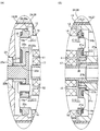
図5(A)は、図2のF部の拡大図であり、図5(B)は、図2のG部の拡大図である。
(Relationship between the rotation axis, planet carrier and main body in the axial direction)
5A is an enlarged view of a portion F in FIG. 2, and FIG. 5B is an enlarged view of a portion G in FIG.
本形態では、遊星キャリア15に作用する前後方向の外力は、太陽歯車11および内歯車13と、1個の遊星歯車12との間に作用する前後方向の磁気的吸引力以下となっている。すなわち、遊星キャリア15に作用する前後方向の外力は、後述の第1回転軸14Aに固定される1個の遊星歯車12と、太陽歯車11および内歯車13との間に作用する前後方向の磁気的吸引力以下となっている。また、本形態では、図2に示すように、遊星歯車12の磁気中心CL1と、太陽歯車11および内歯車13の磁気中心CL2とが前後方向において一致している。
In the present embodiment, the external force in the front-rear direction acting on the
なお、本形態の歯車23は、たとえば、平歯車であり、歯車23には、前後方向の外力がほとんど作用しないため、前後方向と水平方向とが一致するように駆動ユニット2が設置されている場合、遊星キャリア15には、前後方向の外力がほとんど作用しない。また、前後方向が水平方向に対して傾くように駆動ユニット2が設置されている場合であっても、遊星キャリア15に作用する前後方向の外力は、遊星キャリア15および歯車23の重力に起因する外力である。そのため、上述のように、本形態では、遊星キャリア15に作用する前後方向の外力は、太陽歯車11および内歯車13と、1個の遊星歯車12との間に作用する前後方向の磁気的吸引力以下となっている。
Note that the
4本の回転軸14のうちの1本の回転軸14を第1回転軸14Aとし、第1回転軸14Aを除いた残りの3本の回転軸14のそれぞれを第2回転軸14Bとすると、第1回転軸14Aの、段差面14aと段差面14bとの間の大径部分の長さは、第2回転軸14Bの、段差面14aと段差面14bとの間の大径部分の長さよりも長くなっている。本形態では、前後方向の両側で第1回転軸14Aと遊星キャリア15との間に前後方向の隙間が形成されている場合、減速機1の前側では、図5(A)に示すように、第1回転軸14Aの段差面14aと端板部20aの後面との前後方向の隙間C1は、第2回転軸14Bの段差面14aと端板部20aの後面との前後方向の隙間C2よりも小さくなっており、減速機1の後ろ側では、図5(B)に示すように、第1回転軸14Aの段差面14bと保持部材21の前面との前後方向の隙間C3は、第2回転軸14Bの段差面14bと保持部材21の前面との前後方向の隙間C4よりも小さくなっている。
If one of the four
すなわち、本形態では、前側における第1回転軸14Aと遊星キャリア15との前後方向の隙間C1と後ろ側における第1回転軸14Aと遊星キャリア15との前後方向の隙間C3との和は、前側における第2回転軸14Bと遊星キャリア15との前後方向の隙間C2と後ろ側における第2回転軸14Bと遊星キャリア15との前後方向の隙間C4との和よりも小さくなっている。
That is, in this embodiment, the sum of the front-rear direction clearance C1 between the
また、前後方向の両側で第1回転軸14Aと遊星キャリア15との間に前後方向の隙間が形成されている場合、隙間C1は、突出部21cの後端面と当接面27bとの前後方向の隙間C5(図5(B)参照)よりも小さくなっており、隙間C3は、突出部20eの前端面と軸受29の後端面との前後方向の隙間C6(図5(A)参照)よりも小さくなっている。すなわち、前側における第1回転軸14Aと遊星キャリア15との前後方向の隙間C1と後ろ側における第1回転軸14Aと遊星キャリア15との前後方向の隙間C3との和は、前側における遊星キャリア15と本体部16との前後方向の隙間C6と後ろ側における遊星キャリア15と本体部16との前後方向の隙間C5との和よりも小さくなっている。
Further, when a gap in the front-rear direction is formed between the first
そのため、第1回転軸14Aの段差面14aと端板部20aの後面とが接触しているとき、あるいは、第1回転軸14Aの段差面14bと保持部材21の前面とが接触しているときには、第2回転軸14Bの段差面14aと端板部20aの後面との間に隙間が形成され、第2回転軸14Bの段差面14bと保持部材21の前面との間に隙間が形成されるとともに、突出部21cの後端面と当接面27bとの間に隙間が形成され、突出部20eの前端面と軸受29の後端面との間に隙間が形成されている。すなわち、前後方向において第1回転軸14Aと遊星キャリア15とが接触しているときには、前後方向における減速機1の両端側で、第2回転軸14Bと遊星キャリア15との間および遊星キャリア15と本体部16との間に前後方向の隙間が形成されている。
Therefore, when the
上述のように、本形態では、遊星キャリア15に作用する前後方向の外力は、太陽歯車11および内歯車13と、第1回転軸14Aに固定される遊星歯車12との間に作用する前後方向の磁気的吸引力以下となっている。そのため、第1回転軸14Aの段差面14aと端板部20aの後面とが接触している状態から遊星キャリア15がさらに後ろ側に動くことはない。また、第1回転軸14Aの段差面14bと保持部材21の前面とが接触している状態から遊星キャリア15がさらに前側へ動くことはない。したがって、突出部21cの後端面と当接面27bとが接触することはなく、また、突出部20eの前端面と軸受29の後端面とが接触することもない。
As described above, in this embodiment, the longitudinal force acting on the
(本形態の主な効果)
以上説明したように、本形態では、前後方向において第1回転軸14Aと遊星キャリア15とが接触しているときに、前後方向における減速機1の両端側で、第2回転軸14Bと遊星キャリア15との間に前後方向の隙間が形成されている。また、本形態では、遊星歯車12の磁気中心CL1と、太陽歯車11および内歯車13の磁気中心CL2とが前後方向において一致している。そのため、本形態では、1本の回転軸14(具体的には、第1回転軸14A)と遊星キャリア15との間で前後方向における摩擦損失が生じたとしても、残りの3本の第2回転軸14Bと遊星キャリア15との間では、前後方向における摩擦損失が生じない。したがって、本形態では、前後方向(すなわち、回転軸14の軸方向)における減速機1の摩擦損失を低減することが可能になる。
(Main effects of this form)
As described above, in this embodiment, when the first
また、本形態では、遊星キャリア15に作用する前後方向の外力は、太陽歯車11および内歯車13と、第1回転軸14Aに固定される遊星歯車12との間に作用する前後方向の磁気的吸引力以下となっており、上述のように、突出部21cの後端面と当接面27bとが接触することはなく、また、突出部20eの前端面と軸受29の後端面とが接触することもない。したがって、本形態では、遊星キャリア15と本体部16との間で前後方向における摩擦損失が生じない。その結果、本形態では、前後方向における減速機1の摩擦損失を低減することが可能になる。
In this embodiment, the longitudinal external force acting on the
本形態では、太陽歯車11の外径と遊星歯車12の外径とが等しくなっている。そのため、本形態では、太陽歯車11の外周側において太陽歯車11の周方向(円周方向)で隣接配置される遊星歯車12同士の距離を遠ざけることが可能になり、周方向で隣接配置される遊星歯車12の間での磁気干渉を抑制することが可能になる。したがって、本形態では、太陽歯車11と遊星歯車12との間の動力の伝達効率を高めることが可能になる。
In this embodiment, the outer diameter of the
本形態では、太陽歯車11と遊星歯車12とが同形状に形成されている。また、本形態では、太陽歯車11の外周面に着磁される磁極の数と、遊星歯車12の外周面に着磁される磁極の数とが等しくなっている。さらに、本形態では、減速機1の減速比は、1/4となっている。そのため、本形態では、太陽歯車11と遊星歯車12とを共通化できる。したがって、本形態では、減速機1を構成する部品の種類を減らすことが可能になる。また、本形態では、太陽歯車11にモータ3の出力軸3aが連結されており、回転速度が比較的速い位置に減速機1が配置されているため、駆動ユニット2を静音化することが可能になる。
In this embodiment, the
(遊星歯車減速機の変形例)
図6は、本発明の他の実施の形態にかかる減速機1の構成を説明するための図であり、(A)は、図2のF部に相当する部分の拡大図、(B)は、図2のG部に相当する部分の拡大図である。
(Modification of planetary gear reducer)
6A and 6B are diagrams for explaining the configuration of the speed reducer 1 according to another embodiment of the present invention. FIG. 6A is an enlarged view of a portion corresponding to the F portion of FIG. FIG. 3 is an enlarged view of a portion corresponding to a G portion in FIG. 2.
上述した形態では、前後方向において第1回転軸14Aと遊星キャリア15とが接触しているときに、前後方向における減速機1の両端側で、第2回転軸14Bと遊星キャリア15との間および遊星キャリア15と本体部16との間に前後方向の隙間が形成されている。この他にもたとえば、前後方向において遊星キャリア15と本体部16とが接触しているときに、前後方向における減速機1の両端側で、4本の回転軸14と遊星キャリア15との間に前後方向の隙間が形成されても良い。
In the above-described form, when the first
この場合には、たとえば、4本の回転軸14の、段差面14aと段差面14bとの間の大径部分の長さが等しくなっており、4本の回転軸14の、段差面14aと端板部20aの後面との前後方向の隙間C11(図6(A)参照)が互いに等しくなるとともに、4本の回転軸14の、段差面14bと保持部材21の前面との前後方向の隙間C12(図6(B)参照)が互いに等しくなっている。また、この場合には、突出部21cの後端面と当接面27bとの前後方向の隙間C13(図6(B)参照)は、隙間C11よりも小さくなっており、突出部20eの前端面と軸受29の後端面との前後方向の隙間C14(図6(A)参照)は、隙間C12よりも小さくなっている。
In this case, for example, the lengths of the large diameter portions between the step surfaces 14a and 14b of the four
すなわち、前側における遊星キャリア15と本体部16との前後方向の隙間C14と後ろ側における遊星キャリア15と本体部16との前後方向の隙間C13との和は、前側における回転軸14と遊星キャリア15との前後方向の隙間C11と後ろ側における回転軸14と遊星キャリア15との前後方向の隙間C12との和よりも小さくなっている。また、この場合には、遊星キャリア15が前後方向へ移動しても遊星キャリア15と回転軸14とが接触しないため、図2に示すように、遊星歯車12の磁気中心CL1と、太陽歯車11および内歯車13の磁気中心CL2とは前後方向において一致している。
That is, the sum of the front-rear clearance C14 between the
この場合には、遊星キャリア15と本体部16との間では前後方向の摩擦損失が生じるが、4本の回転軸14と遊星キャリア15との間では、前後方向の摩擦損失が生じない。したがって、この場合であっても、前後方向における減速機1の摩擦損失を低減することが可能になる。ただし、遊星キャリア15と本体部16との前後方向の接触面積は、第1回転軸14Aと遊星キャリア15との前後方向の接触面積よりも大きくなるため、上述した形態の方が、前後方向における減速機1の摩擦損失を効果的に低減することが可能になる。
In this case, a longitudinal friction loss occurs between the
なお、上述した形態において、遊星キャリア15に作用する前後方向の外力が、太陽歯車11および内歯車13と、1個の遊星歯車12との間に作用する前後方向の磁気的吸引力よりも大きくなっている場合には、第1回転軸14Aの段差面14aと端板部20aの後面とが接触している状態から遊星キャリア15がさらに後ろ側に動いたり、第1回転軸14Aの段差面14bと保持部材21の前面とが接触している状態から遊星キャリア15がさらに前側へ動いたりするおそれがある。そのため、この場合には、第1回転軸14Aの段差面14aと端板部20aの後面とが接触し、かつ、突出部21cの後端面と当接面27bとが接触するおそれがあるとともに、第1回転軸14Aの段差面14bと保持部材21の前面とが接触し、かつ、突出部20eの前端面と軸受29の後端面とが接触するおそれがある。すなわち、この場合には、前後方向において第1回転軸14Aと遊星キャリア15とが接触し、かつ、前後方向において遊星キャリア15と本体部16とが接触するおそれがある。
In the embodiment described above, the front-rear direction external force acting on the
これに対して、遊星キャリア15に作用する前後方向の外力が、太陽歯車11および内歯車13と、1個の遊星歯車12との間に作用する前後方向の磁気的吸引力よりも大きくなっている場合であっても、図6に示す変形例のように、前後方向において遊星キャリア15と本体部16とが接触しているときに、前後方向における減速機1の両端側で、4本の回転軸14と遊星キャリア15との間に前後方向の隙間が形成されていれば、前後方向において、4本の回転軸14と遊星キャリア15とが接触せず、前後方向における減速機1の摩擦損失をより低減することが可能になる。したがって、遊星キャリア15に作用する前後方向の外力が、太陽歯車11および内歯車13と、1個の遊星歯車12との間に作用する前後方向の磁気的吸引力よりも大きくなっている場合には、前後方向において遊星キャリア15と本体部16とが接触しているときに、前後方向における減速機1の両端側で、4本の回転軸14と遊星キャリア15との間に前後方向の隙間が形成されている方が好ましい。
On the other hand, the longitudinal force acting on the
なお、遊星キャリア15に作用する前後方向の外力が、太陽歯車11および内歯車13と、1個の遊星歯車12との間に作用する前後方向の磁気的吸引力よりも大きくなっている場合は、たとえば、歯車23がはすば歯車の場合、歯車23に代えて、ウォーム(ネジ歯車)やかさ歯車が軸部22bの前端側に固定される場合、あるいは、歯車23に代えて、羽根車が軸部22bの前端側に固定される場合等である。
When the external force in the front-rear direction acting on the
(他の実施の形態)
上述した形態は、本発明の好適な形態の一例ではあるが、これに限定されるものではなく本発明の要旨を変更しない範囲において種々変形実施が可能である。
(Other embodiments)
The above-described embodiment is an example of a preferred embodiment of the present invention, but is not limited to this, and various modifications can be made without departing from the scope of the present invention.
上述した形態では、3本の第2回転軸14Bの形状が同形状となっているが、3本の第2回転軸14Bの中に形状の異なるものがあっても良い。また、上述した形態では、減速機1が備える遊星歯車12の数は4個であるが、減速機1が備える遊星歯車12の数は、4個以外の数であっても良い。すなわち、減速機1が備える回転軸14の数は、4本以外であっても良い。また、上述した形態では、太陽歯車11と遊星歯車12とが同形状に形成されているが、太陽歯車11の形状と遊星歯車12の形状とが異なっていても良い。たとえば、太陽歯車11の外径と遊星歯車12の外径とが異なっていても良い。
In the embodiment described above, the three second
上述した形態では、減速機4は機械式の減速機であるが、減速機4は磁気式の減速機であっても良い。また、上述した形態では、駆動ユニット2は、減速機4を備えているが、駆動ユニット2は、減速機4を備えていなくても良い。この場合には、ネジ部材6は、減速機1の出力軸に連結される。さらに、上述した形態では、駆動ユニット2が備える減速機1の数は1個であるが、駆動ユニット2は、直列に接続される2個以上の減速機1を備えていても良い。また、上述した形態では、駆動ユニット2は、動作対象物を直線的に移動させるが、駆動ユニット2は、動作対象物を回転させても良い。 In the embodiment described above, the speed reducer 4 is a mechanical speed reducer, but the speed reducer 4 may be a magnetic speed reducer. Moreover, in the form mentioned above, although the drive unit 2 is provided with the reduction gear 4, the drive unit 2 does not need to be provided with the reduction gear 4. FIG. In this case, the screw member 6 is connected to the output shaft of the speed reducer 1. Furthermore, in the embodiment described above, the drive unit 2 includes one speed reducer 1, but the drive unit 2 may include two or more speed reducers 1 connected in series. Moreover, in the form mentioned above, although the drive unit 2 moves an operation target linearly, the drive unit 2 may rotate an operation target.
1 減速機(遊星歯車減速機)
3 モータ
3a 出力軸
4 減速機
5 駆動機構
11 太陽歯車(磁気式太陽歯車)
12 遊星歯車(磁気式遊星歯車)
13 内歯車(磁気式内歯車)
14 回転軸
14A 第1回転軸
14B 第2回転軸
15 遊星キャリア
16 本体部
CL1 磁気式太陽歯車および磁気式内歯車の磁気中心
CL2 磁気式遊星歯車の磁気中心
1 Reducer (Planetary gear reducer)
3
12 Planetary gear (magnetic planetary gear)
13 Internal gear (magnetic internal gear)
DESCRIPTION OF
Claims (8)
複数の前記回転軸は、前記遊星キャリアに対して前記回転軸の軸方向への移動が可能となるように前記遊星キャリアに保持され、
前記遊星キャリアは、前記本体部に対して前記軸方向への移動が可能となるように前記本体部に保持され、
複数の前記回転軸のうちの1本の前記回転軸を第1回転軸とし、前記第1回転軸を除いた残りの前記回転軸のそれぞれを第2回転軸とすると、
前記軸方向の一端側における前記第1回転軸と前記遊星キャリアとの前記軸方向の隙間と前記軸方向の他端側における前記第1回転軸と前記遊星キャリアとの前記軸方向の隙間との和は、前記軸方向の一端側における前記第2回転軸と前記遊星キャリアとの前記軸方向の隙間と前記軸方向の他端側における前記第2回転軸と前記遊星キャリアとの前記軸方向の隙間との和、および、前記軸方向の一端側における前記遊星キャリアと前記本体部との前記軸方向の隙間と前記軸方向の他端側における前記遊星キャリアと前記本体部との前記軸方向の隙間との和よりも小さくなっており、
前記軸方向において前記第1回転軸と前記遊星キャリアとが接触しているときに、前記軸方向における両端側で、前記第2回転軸と前記遊星キャリアとの間および前記遊星キャリアと前記本体部との間に前記軸方向の隙間が形成されていることを特徴とする遊星歯車減速機。 A magnetic sun gear, a plurality of magnetic planetary gears that revolve while rotating around the magnetic sun gear, and a magnetic internal gear arranged so as to surround the plurality of magnetic planetary gears from the outer peripheral side, A plurality of rotation shafts to which each of the plurality of magnetic planetary gears is fixed; a planet carrier that rotatably holds the plurality of rotation shafts; and the magnetic internal gear that rotatably holds the planet carrier and A fixed body part,
A plurality of the rotation shafts are held by the planet carrier so as to be able to move in the axial direction of the rotation shaft with respect to the planet carrier,
The planet carrier is held by the main body so as to be movable in the axial direction with respect to the main body,
When one of the plurality of rotating shafts is a first rotating shaft and each of the remaining rotating shafts excluding the first rotating shaft is a second rotating shaft,
A gap in the axial direction between the first rotating shaft and the planet carrier on one end side in the axial direction and a gap in the axial direction between the first rotating shaft and the planet carrier on the other end side in the axial direction. The sum of the axial gap between the second rotating shaft and the planet carrier on one end side in the axial direction and the axial direction between the second rotating shaft and the planet carrier on the other end side in the axial direction. The sum of the gap, the gap in the axial direction between the planet carrier and the main body at one end side in the axial direction, and the axial direction between the planet carrier and the main body at the other end side in the axial direction. It is smaller than the sum with the gap,
When the first rotating shaft and the planet carrier are in contact with each other in the axial direction, on both ends in the axial direction, between the second rotating shaft and the planet carrier, and the planet carrier and the main body portion. A planetary gear reducer characterized in that a gap in the axial direction is formed therebetween.
前記遊星キャリアに作用する前記軸方向の外力は、前記磁気式太陽歯車および前記磁気式内歯車と、前記第1回転軸に固定される前記磁気式遊星歯車との間に作用する前記軸方向の磁気的吸引力以下となっていることを特徴とする請求項1記載の遊星歯車減速機。 The magnetic center of the magnetic sun gear and the magnetic internal gear in the axial direction and the magnetic center of the magnetic planetary gear in the axial direction coincide in the axial direction;
The axial external force acting on the planet carrier is the axial force acting between the magnetic sun gear and the magnetic internal gear and the magnetic planet gear fixed to the first rotating shaft. 2. The planetary gear reducer according to claim 1, wherein the planetary gear reducer has a magnetic attraction force or less.
複数の前記回転軸は、前記遊星キャリアに対して前記回転軸の軸方向への移動が可能となるように前記遊星キャリアに保持され、
前記遊星キャリアは、前記本体部に対して前記軸方向への移動が可能となるように前記本体部に保持され、
前記軸方向の一端側における前記遊星キャリアと前記本体部との前記軸方向の隙間と前記軸方向の他端側における前記遊星キャリアと前記本体部との前記軸方向の隙間との和は、前記軸方向の一端側における前記回転軸と前記遊星キャリアとの前記軸方向の隙間と前記軸方向の他端側における前記回転軸と前記遊星キャリアとの前記軸方向の隙間との和よりも小さくなっており、
前記軸方向において前記遊星キャリアと前記本体部とが接触しているときに、前記軸方向における両端側で、前記回転軸と前記遊星キャリアとの間に前記軸方向の隙間が形成され、
前記軸方向における前記磁気式太陽歯車および前記磁気式内歯車の磁気中心と、前記軸方向における前記磁気式遊星歯車の磁気中心とが前記軸方向において一致しており、
前記遊星キャリアに作用する前記軸方向の外力は、前記磁気式太陽歯車および前記磁気式内歯車と、1個の前記磁気式遊星歯車との間に作用する前記軸方向の磁気的吸引力よりも大きくなっていることを特徴とする遊星歯車減速機。 A magnetic sun gear, a plurality of magnetic planetary gears that revolve while rotating around the magnetic sun gear, and a magnetic internal gear arranged so as to surround the plurality of magnetic planetary gears from the outer peripheral side, A plurality of rotation shafts to which each of the plurality of magnetic planetary gears is fixed; a planet carrier that rotatably holds the plurality of rotation shafts; and the magnetic internal gear that rotatably holds the planet carrier and A fixed body part,
A plurality of the rotation shafts are held by the planet carrier so as to be able to move in the axial direction of the rotation shaft with respect to the planet carrier,
The planet carrier is held by the main body so as to be movable in the axial direction with respect to the main body,
The sum of the axial gap between the planet carrier and the main body at one end in the axial direction and the axial gap between the planet carrier and the main body at the other end in the axial direction is: Less than the sum of the axial clearance between the rotating shaft and the planet carrier on one end side in the axial direction and the axial clearance between the rotating shaft and the planet carrier on the other end side in the axial direction. And
When the planetary carrier and the main body are in contact with each other in the axial direction, the axial gap is formed between the rotating shaft and the planetary carrier on both ends in the axial direction ,
The magnetic center of the magnetic sun gear and the magnetic internal gear in the axial direction and the magnetic center of the magnetic planetary gear in the axial direction coincide in the axial direction;
The axial external force acting on the planet carrier is larger than the axial magnetic attraction force acting between the magnetic sun gear and the magnetic internal gear and one magnetic planet gear. A planetary gear reducer characterized by an increase in size .
前記磁気式太陽歯車の外周面の磁極の数と、前記磁気式遊星歯車の外周面の磁極の数とが等しいことを特徴とする請求項5記載の遊星歯車減速機。 The magnetic sun gear and the magnetic planetary gear are formed in the same shape,
6. The planetary gear reducer according to claim 5 , wherein the number of magnetic poles on the outer peripheral surface of the magnetic sun gear is equal to the number of magnetic poles on the outer peripheral surface of the magnetic planetary gear.
Priority Applications (2)
| Application Number | Priority Date | Filing Date | Title |
|---|---|---|---|
| US15/213,863 US10404151B2 (en) | 2015-08-07 | 2016-07-19 | Planetary gear speed reduction device and driving mechanism |
| CN201610578487.0A CN106438857A (en) | 2015-08-07 | 2016-07-21 | Planetary gear speed reduction device and driving mechanism |
Applications Claiming Priority (2)
| Application Number | Priority Date | Filing Date | Title |
|---|---|---|---|
| US201562202418P | 2015-08-07 | 2015-08-07 | |
| US62/202,418 | 2015-08-07 |
Publications (2)
| Publication Number | Publication Date |
|---|---|
| JP2017036824A JP2017036824A (en) | 2017-02-16 |
| JP6604820B2 true JP6604820B2 (en) | 2019-11-13 |
Family
ID=58047487
Family Applications (2)
| Application Number | Title | Priority Date | Filing Date |
|---|---|---|---|
| JP2015213891A Expired - Fee Related JP6604820B2 (en) | 2015-08-07 | 2015-10-30 | Planetary gear reducer and drive mechanism |
| JP2015213892A Pending JP2017036825A (en) | 2015-08-07 | 2015-10-30 | Planetary gear speed reducer and drive mechanism |
Family Applications After (1)
| Application Number | Title | Priority Date | Filing Date |
|---|---|---|---|
| JP2015213892A Pending JP2017036825A (en) | 2015-08-07 | 2015-10-30 | Planetary gear speed reducer and drive mechanism |
Country Status (3)
| Country | Link |
|---|---|
| US (1) | US10404151B2 (en) |
| JP (2) | JP6604820B2 (en) |
| CN (1) | CN106438857A (en) |
Families Citing this family (9)
| Publication number | Priority date | Publication date | Assignee | Title |
|---|---|---|---|---|
| JP6604820B2 (en) * | 2015-08-07 | 2019-11-13 | 日本電産サンキョー株式会社 | Planetary gear reducer and drive mechanism |
| CN107659114B (en) * | 2017-06-11 | 2019-11-12 | 珠海磐磊智能科技有限公司 | Motor, control moment gyroscope and mobile devices |
| CN107453582B (en) * | 2017-09-18 | 2019-11-26 | 安徽沃弗电力科技有限公司 | A kind of permanent-magnet speed governor of the magnetic conduction body disc based on high thermal conductivity |
| CN108206622B (en) * | 2018-01-10 | 2019-08-23 | 山东大学 | A kind of mixing of electromagnetism is without gear ring planetary gear speed-changing system |
| JP7160250B2 (en) * | 2018-09-25 | 2022-10-25 | Smc株式会社 | Reduction ratio automatic switching device |
| CN110266176A (en) * | 2019-04-30 | 2019-09-20 | 苏州博安捷机器人科技有限公司 | A kind of Magnetic drive dual-range transmission |
| CN110798048A (en) * | 2019-09-30 | 2020-02-14 | 中北大学 | Transmission mechanism for spaceflight |
| CN110848354B (en) * | 2019-09-30 | 2021-10-15 | 中北大学 | Transmission method for spaceflight based on adsorption transmission |
| KR20230135407A (en) * | 2022-03-16 | 2023-09-25 | 현대자동차주식회사 | Hybrid power train for vehicle |
Family Cites Families (39)
| Publication number | Priority date | Publication date | Assignee | Title |
|---|---|---|---|---|
| US3915031A (en) * | 1974-10-24 | 1975-10-28 | Caterpillar Tractor Co | Dual mode drive differential mechanism |
| US4091689A (en) * | 1976-09-01 | 1978-05-30 | Dana Corporation | Planetary steering hub assembly |
| JPS5635849A (en) * | 1979-08-30 | 1981-04-08 | Kubota Ltd | Variable speed gear for tractor |
| US4824419A (en) * | 1988-07-05 | 1989-04-25 | Kumm Industries, Inc. | Flat belt continuously variable transmission with geared speed ratio control system |
| US5013949A (en) * | 1990-06-25 | 1991-05-07 | Sundstrand Corporation | Magnetic transmission |
| JPH04321848A (en) * | 1991-04-18 | 1992-11-11 | Tochigi Fuji Ind Co Ltd | Planetary gear mechanism |
| SE470256B (en) * | 1991-05-21 | 1993-12-20 | Linvent Ab | Device for mutual angle adjustment of two units, preferably adjustment of the backrest closure of a vehicle seat |
| JP3387935B2 (en) * | 1991-07-08 | 2003-03-17 | 株式会社東芝 | Planetary gear set |
| US5385514A (en) * | 1993-08-11 | 1995-01-31 | Excelermalic Inc. | High ratio planetary transmission |
| US5730232A (en) * | 1996-04-10 | 1998-03-24 | Mixer; John E. | Two-speed fastener driver |
| US5692989A (en) * | 1996-06-06 | 1997-12-02 | Kamlukin; Igor | Self aligning planetary gear transmission & speed reducer |
| TW512211B (en) * | 1999-03-16 | 2002-12-01 | Sumitomo Heavy Industries | Driving device |
| KR100304140B1 (en) * | 1999-05-20 | 2001-09-24 | 배명순 | Reduction apparatus |
| JP2001289153A (en) * | 2000-04-05 | 2001-10-19 | Kenji Nozaki | Magnetic force rotating engine having planetary gear device provided with magnets arranged and fixed on whole circumference of frame inner surface |
| DE10047312A1 (en) * | 2000-09-25 | 2002-05-08 | Hilti Ag | Controllable planetary gear |
| JP2005315370A (en) * | 2004-04-30 | 2005-11-10 | Chugoku Electric Power Co Inc:The | Power transmission device |
| JP2005335536A (en) * | 2004-05-27 | 2005-12-08 | Sanyo Electric Co Ltd | Hub unit for electromotive vehicle wheel, and vehicle with the hub unit |
| JP2005335535A (en) * | 2004-05-27 | 2005-12-08 | Sanyo Electric Co Ltd | Hub unit for electromotive vehicle, and vehicle with the hub unit |
| JP4899082B2 (en) * | 2004-06-08 | 2012-03-21 | Smc株式会社 | Automatic reduction ratio switching device |
| JP2006038110A (en) * | 2004-07-27 | 2006-02-09 | Matsushita Electric Works Ltd | Gear transmission mechanism, and planetary gear mechanism |
| EP1970580B1 (en) * | 2005-12-27 | 2012-11-14 | Mitsubishi Heavy Industries, Ltd. | Planetary roller reduction gear |
| US7980324B2 (en) * | 2006-02-03 | 2011-07-19 | Black & Decker Inc. | Housing and gearbox for drill or driver |
| JP2007252174A (en) * | 2006-02-15 | 2007-09-27 | Venera Laboratory Co Ltd | Geared motor and planetary geared dynamo |
| JP4789000B2 (en) * | 2006-02-16 | 2011-10-05 | Smc株式会社 | Automatic reduction ratio switching device |
| JP5137683B2 (en) * | 2008-05-20 | 2013-02-06 | キヤノン株式会社 | Coreless motor |
| JP4674640B2 (en) * | 2009-01-27 | 2011-04-20 | パナソニック電工株式会社 | Impact rotary tool |
| US20120025644A1 (en) * | 2009-04-21 | 2012-02-02 | Toyota Jidosha Kabushiki Kaisha | Electric motor having speed change function |
| TWI425154B (en) * | 2009-06-23 | 2014-02-01 | Metal Ind Res & Dev Ct | Concentric alignment planetary gear set and power transmission |
| US8584770B2 (en) * | 2010-03-23 | 2013-11-19 | Black & Decker Inc. | Spindle bearing arrangement for a power tool |
| JP2012063008A (en) * | 2010-08-19 | 2012-03-29 | Ricoh Co Ltd | Drive reduction gear and image forming apparatus |
| JP2012163186A (en) * | 2011-02-09 | 2012-08-30 | Toyota Central R&D Labs Inc | Planetary gear speed converter |
| JP5840614B2 (en) * | 2012-02-24 | 2016-01-06 | 日鍛バルブ株式会社 | Planetary gear reducer |
| JP5822817B2 (en) * | 2012-11-21 | 2015-11-24 | 住友重機械工業株式会社 | Wheel drive device |
| US20160156248A1 (en) * | 2014-12-01 | 2016-06-02 | David Lueker | Low Profile Motor |
| TWI530066B (en) * | 2014-12-02 | 2016-04-11 | Prec Machinery Res &Development Ct | Hollow motor module |
| US10458270B2 (en) * | 2015-06-23 | 2019-10-29 | United Technologies Corporation | Roller bearings for high ratio geared turbofan engine |
| JP6604820B2 (en) * | 2015-08-07 | 2019-11-13 | 日本電産サンキョー株式会社 | Planetary gear reducer and drive mechanism |
| JP6696179B2 (en) * | 2016-01-13 | 2020-05-20 | 株式会社ジェイテクト | Differential |
| JP6531748B2 (en) * | 2016-11-18 | 2019-06-19 | トヨタ自動車株式会社 | Motion conversion mechanism and electric brake actuator using the same |
-
2015
- 2015-10-30 JP JP2015213891A patent/JP6604820B2/en not_active Expired - Fee Related
- 2015-10-30 JP JP2015213892A patent/JP2017036825A/en active Pending
-
2016
- 2016-07-19 US US15/213,863 patent/US10404151B2/en not_active Expired - Fee Related
- 2016-07-21 CN CN201610578487.0A patent/CN106438857A/en not_active Withdrawn
Also Published As
| Publication number | Publication date |
|---|---|
| JP2017036824A (en) | 2017-02-16 |
| US10404151B2 (en) | 2019-09-03 |
| CN106438857A (en) | 2017-02-22 |
| JP2017036825A (en) | 2017-02-16 |
| US20170040880A1 (en) | 2017-02-09 |
Similar Documents
| Publication | Publication Date | Title |
|---|---|---|
| JP6604820B2 (en) | Planetary gear reducer and drive mechanism | |
| US8663049B1 (en) | Speed reducer | |
| US11078989B2 (en) | Reduction gear and electromechanical device | |
| JP2017203546A (en) | Driving device | |
| KR102519998B1 (en) | Drive apparatus | |
| JP2010096319A (en) | Gear transmission device | |
| JP6160440B2 (en) | Planetary gear set | |
| JP3186812U (en) | Variable speed transmission bearing | |
| JP5608374B2 (en) | Gear transmission | |
| JP2017214947A (en) | Gear reducer | |
| JP2012137113A (en) | Shaft device | |
| JP2014126048A (en) | Gear and electric motor using gear | |
| KR102275048B1 (en) | Reduction device with high reduction ratio performance | |
| JP2012016200A (en) | Cylindrical motor | |
| JP2017077088A (en) | Motor unit | |
| JP2011247348A (en) | Meshed gear for vehicle | |
| KR20060008147A (en) | Epicyclic gear trains | |
| KR101505414B1 (en) | End-cover for reducer | |
| JP2017040312A (en) | Reduction gear | |
| TW202118953A (en) | Reducer with high speed reduction ratio comprises an input shaft, a first cycloid gear, a first ring gear, a first output set, a second cycloid gear, a second ring gear, and a second output set | |
| JP2016141311A (en) | Support structure of rotating shaft of vehicle | |
| JP2019058031A (en) | Series of electric actuators | |
| KR20160125642A (en) | Worm geared speed reducer | |
| JP2016075369A (en) | Inscription engagement planetary gear mechanism | |
| CN105736667A (en) | Push type speed change mechanism |
Legal Events
| Date | Code | Title | Description |
|---|---|---|---|
| A621 | Written request for application examination |
Free format text: JAPANESE INTERMEDIATE CODE: A621 Effective date: 20180911 |
|
| A977 | Report on retrieval |
Free format text: JAPANESE INTERMEDIATE CODE: A971007 Effective date: 20190725 |
|
| A131 | Notification of reasons for refusal |
Free format text: JAPANESE INTERMEDIATE CODE: A131 Effective date: 20190801 |
|
| A521 | Request for written amendment filed |
Free format text: JAPANESE INTERMEDIATE CODE: A523 Effective date: 20190919 |
|
| TRDD | Decision of grant or rejection written | ||
| A01 | Written decision to grant a patent or to grant a registration (utility model) |
Free format text: JAPANESE INTERMEDIATE CODE: A01 Effective date: 20191003 |
|
| A61 | First payment of annual fees (during grant procedure) |
Free format text: JAPANESE INTERMEDIATE CODE: A61 Effective date: 20191015 |
|
| R150 | Certificate of patent or registration of utility model |
Ref document number: 6604820 Country of ref document: JP Free format text: JAPANESE INTERMEDIATE CODE: R150 |
|
| LAPS | Cancellation because of no payment of annual fees |