JP5137683B2 - Coreless motor - Google Patents
Coreless motor Download PDFInfo
- Publication number
- JP5137683B2 JP5137683B2 JP2008131737A JP2008131737A JP5137683B2 JP 5137683 B2 JP5137683 B2 JP 5137683B2 JP 2008131737 A JP2008131737 A JP 2008131737A JP 2008131737 A JP2008131737 A JP 2008131737A JP 5137683 B2 JP5137683 B2 JP 5137683B2
- Authority
- JP
- Japan
- Prior art keywords
- attached
- motor shaft
- planetary gear
- outer cylinder
- unit
- Prior art date
- Legal status (The legal status is an assumption and is not a legal conclusion. Google has not performed a legal analysis and makes no representation as to the accuracy of the status listed.)
- Active
Links
Images


Classifications
-
- H—ELECTRICITY
- H02—GENERATION; CONVERSION OR DISTRIBUTION OF ELECTRIC POWER
- H02K—DYNAMO-ELECTRIC MACHINES
- H02K7/00—Arrangements for handling mechanical energy structurally associated with dynamo-electric machines, e.g. structural association with mechanical driving motors or auxiliary dynamo-electric machines
- H02K7/10—Structural association with clutches, brakes, gears, pulleys or mechanical starters
- H02K7/116—Structural association with clutches, brakes, gears, pulleys or mechanical starters with gears
-
- H—ELECTRICITY
- H02—GENERATION; CONVERSION OR DISTRIBUTION OF ELECTRIC POWER
- H02K—DYNAMO-ELECTRIC MACHINES
- H02K23/00—DC commutator motors or generators having mechanical commutator; Universal AC/DC commutator motors
- H02K23/58—Motors or generators without iron cores
-
- H—ELECTRICITY
- H02—GENERATION; CONVERSION OR DISTRIBUTION OF ELECTRIC POWER
- H02K—DYNAMO-ELECTRIC MACHINES
- H02K5/00—Casings; Enclosures; Supports
- H02K5/04—Casings or enclosures characterised by the shape, form or construction thereof
- H02K5/14—Means for supporting or protecting brushes or brush holders
- H02K5/143—Means for supporting or protecting brushes or brush holders for cooperation with commutators
- H02K5/145—Fixedly supported brushes or brush holders, e.g. leaf or leaf-mounted brushes
Description
本発明は、減速機構を備えたコアレスモータに関するものである。 The present invention relates to a coreless motor including a speed reduction mechanism.
モータから減速された出力を取り出すには、モータ出力軸と所望の出力軸の間に減速機構を設ける手法が一般的であり、減速機構はモータ外部あるいは内部に取り付けられる。内部に取り付けられる場合であっても、多くはモータハウジング内に減速機構が収まっているだけで、該減速機構は電機子や固定子といったモータ基本構成部の外部に配置されている(特許文献1)。 In order to take out the decelerated output from the motor, a method of providing a reduction mechanism between the motor output shaft and a desired output shaft is generally used, and the reduction mechanism is attached outside or inside the motor. Even in the case of being mounted inside, in many cases, the speed reduction mechanism is only accommodated in the motor housing, and the speed reduction mechanism is disposed outside the motor basic components such as the armature and the stator (Patent Document 1). ).
特許文献1において、個別に組み立てられていたモータとギヤヘッド(減速機構)とを同一のハウジング内に装填したことによる恩恵は、モータと減速機構の位置出しに不可欠な中間部品を廃止できたことである。また、その分の調整作業の廃止による組み立て工数の削減などである。
しかしながら、上記特許文献1のモータは、減速機構の一体化によって実現された小型化は僅かなものである。つまり、減速機構を一体化したモータを小型化(全長を短く)するには、モータ構造を含めた抜本的な見直しが必要であった。
However, the motor of
(発明の目的)
本発明の目的は、小型化することのみならず、モータ軸とマグネット、外筒との必要な同軸度を確保しやすく、組み立て作業の容易な構造のコアレスモータを提供しようとするものである。
(Object of invention)
An object of the present invention is to provide a coreless motor having a structure that facilitates not only miniaturization, but also ensures the required coaxiality between a motor shaft, a magnet, and an outer cylinder, and facilitates assembly work.
上記目的を達成するために、本発明の一側面としてのコアレスモータは、遊星ギヤユニットと、前記遊星ギヤユニットの遊星歯車と噛み合う内歯車が形成される内部継鉄と、前記内部継鉄の外周に配置される円筒状のマグネットと、前記マグネットの外周に配置される外筒とを含む外筒・ギヤユニットと、前記内部継鉄に取り付けられる中蓋と、前記中蓋を前記内部継鉄に取り付けた際に、前記遊星ギヤユニットの遊星歯車と噛み合うピニオンギヤが取り付けられたモータ軸と、前記モータ軸を前記中蓋に対して回転可能に軸受けする一対の軸受とを含むモータ軸ユニットと、前記モータ軸に取り付けられる円板と、前記円板に取り付けられる整流子と、前記円板に固定され、前記整流子と電気的に接続される円筒形のコイルとを含むロータユニットと、前記外筒に取り付けられる後蓋と、前記後蓋に固定され、前記後蓋が前記外筒に取り付けられた際に、前記整流子と接触するブラシとを含む後蓋ユニットとを有し、前記ピニオンギヤが前記遊星ギヤユニットの遊星歯車と噛み合うように前記中蓋を前記内部継鉄に取り付けた後、前記コイルが前記マグネットと前記外筒との間に位置するように前記モータ軸に前記円板を取り付け、その後、前記外筒に前記後蓋を取り付けることを特徴とする。
また、本発明の他の側面としてのコアレスモータは、モータ軸と、前記モータ軸に取り付けられるピニオンギヤと、前記ピニオンギヤと噛みあう遊星歯車を有する遊星ギヤユニットと、前記遊星ギヤユニットの遊星歯車と噛みあう内歯車が形成される内部継鉄と、前記内部継鉄に固定される中蓋と、前記中蓋に前記モータ軸を軸受けする一対の軸受と、前記内部継鉄の外周に配置される円筒状のマグネットと、前記内部継鉄に固定され、前記マグネットの外周に配置される外筒と、前記マグネットと前記外筒との間に配置され、通電されることで前記モータ軸を中心として、前記マグネットに対して回転するコイルと、前記コイルと電気的に接続される整流子と、前記整流子が取り付けられ、前記コイルに固定される円板と、前記整流子と接触するブラシと、前記ブラシが取り付けられ、前記外筒に固定される後蓋と、を有することを特徴とする。
To achieve the above object, a coreless motor according to one aspect of the present invention includes a planetary gear unit, an internal yoke that forms an internal gear that meshes with the planetary gear of the planetary gear unit, and an outer periphery of the internal yoke. An outer cylinder / gear unit including a cylindrical magnet disposed on the outer periphery of the magnet, an inner lid attached to the inner yoke, and the inner lid as the inner yoke. when mounted, the motor shaft pinion gear meshing with the planetary gears mounted in the planetary gear unit, a motor shaft unit comprising a pair of bearings which bearing rotatably said motor shaft with respect to the inner lid, the rotor comprising a disc mounted on the motor shaft, a commutator mounted on the circular plate, is fixed to the circular plate, and a cylindrical coil which is the commutator electrically connected Yes and knit, a lid after attached to the outer cylinder is fixed to the rear cover, when the rear cover is attached to the outer cylinder, and a cover unit after including the brushes in contact with the commutator Then, after attaching the inner lid to the inner yoke so that the pinion gear meshes with the planetary gear of the planetary gear unit, the coil is positioned on the motor shaft so that the coil is positioned between the magnet and the outer cylinder. The disc is attached, and then the rear lid is attached to the outer cylinder .
A coreless motor according to another aspect of the present invention includes a motor shaft, a pinion gear attached to the motor shaft, a planetary gear unit having a planetary gear meshing with the pinion gear, and a planetary gear of the planetary gear unit. An internal yoke in which a mating internal gear is formed, an inner lid fixed to the inner yoke, a pair of bearings for bearing the motor shaft on the inner lid, and a cylinder disposed on the outer periphery of the inner yoke A magnet, an outer cylinder fixed to the inner yoke, arranged on the outer periphery of the magnet, arranged between the magnet and the outer cylinder, and energized around the motor shaft, A coil that rotates with respect to the magnet; a commutator that is electrically connected to the coil; a disk to which the commutator is attached and fixed to the coil; And brushes, wherein the brush is mounted, and having a, a lid after being fixed to the outer cylinder.
本発明によれば、小型化することのみならず、モータ軸とマグネット、外筒との必要な同軸度を確保しやすく、組み立て作業の容易な構造のコアレスモータを提供できるものである。 According to the present invention, it is possible to provide a coreless motor having a structure that facilitates not only miniaturization, but also ensures the necessary coaxiality between the motor shaft, the magnet, and the outer cylinder, and facilitates assembly work.
本発明を実施するための最良の形態は、以下の実施例に示す通りである。 The best mode for carrying out the present invention is as shown in the following examples.
ここで、本発明の実施例の説明に入る前に、以下に説明する実施例のコアレスモータの前提となるモータについて説明する。 Here, before the description of the embodiment of the present invention, a motor which is a premise of the coreless motor of the embodiment described below will be described.
減速機を有するモータには、例えば特許文献1のように、モータと同一ハウジング内に減速機構を設けたものが提案されており、この種の多くは、モータと減速機のハウジングを一体化したに過ぎない。この点に鑑み、特にモータ部分をコアレスモータとし、界磁マグネットの内部継鉄の役割を減速機のハウジングが兼ねるように、すなわちマグネットに内包するように減速機を配置し、モータ全長を短縮できるようにした減速機内包型コアレスモータが考えられる。
As a motor having a speed reducer, for example, as disclosed in
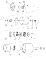
この減速機内包型コアレスモータの基本構成について、図7ないし図9を用いて説明する。なお、図7はコアレスモータの分解斜視図、図8はコアレスモータの組み立て途中の状態を示す斜視図、図9はコアレスモータの組み立て完了状態を示す断面図である。 The basic configuration of the speed reducer-embedded coreless motor will be described with reference to FIGS. 7 is an exploded perspective view of the coreless motor, FIG. 8 is a perspective view showing a state during the assembly of the coreless motor, and FIG. 9 is a cross-sectional view showing a state where the coreless motor is assembled.
図7において、まず、磁性体で作られた内部継鉄兼内歯車6に円筒状のマグネット7(界磁マグネット)を取り付け、さらに外筒4を取り付けて界磁組を形成する。そして、出力軸5、太陽歯車9、遊星歯車8を組み込み、中蓋10を有する後蓋ユニット3(図8参照)が取り付けられる外筒・ギヤユニット1(図8参照)を完成する。ここで、中蓋10の中心の孔はモータ軸13の出力側軸受14の台座を兼ねており、後にロータユニット2(図8参照)の円筒状のコイル11が収まるマグネット7の外径と外筒4の内径の空隙に対して、中心軸が精度良く一致している必要がある。そのためには、中蓋10が取り付けられる内歯車6の内径とマグネット7の外径部、外筒4の内径を精度良く組み付けておかなければならない。加えて中蓋10の外径と内径、さらには軸受14の外径と内径の同軸度など、部品単体としての精度も求められる。
In FIG. 7, first, a cylindrical magnet 7 (field magnet) is attached to an internal yoke and
次に、モータ軸13の反出力側の軸受20について考えると、軸受20は後蓋21に取り付けられ、これら軸受20、後蓋21およびブラシばね18、端子19、ブラシ22より成る後蓋ユニット3(図8参照)が外筒・ギヤユニット1に取り付けられる。ここでは後蓋ユニット3と外筒4の取り付け精度のほかに、外筒内径と外筒4の後蓋取り付け部内径との同軸度、後蓋21の外径と後蓋21の軸受取り付け部内径との同軸度、軸受20の外径と内径の同軸度などの部品精度が求められる。
Next, considering the
図9に示すように組み立て完了したコアレスモータは、マグネット7の外径と外筒4の内径の間の空隙えロータのコイル11が回転する構造である。よって、少なくともロータの軸(モータ軸13)を支承する前後の軸受14,20は、その中心がマグネット外径と外筒内径の中心軸同士と精度良く一致していなければならない。
As shown in FIG. 9, the assembled coreless motor has a structure in which the
しかしながら、上述したように減速機内包型コアレスモータの場合、小型化は達成できるが、軸受とマグネット外径、外筒内径との間に介在する部品や組み立て工程が多い。このため、それぞれの部品精度と組み立て精度の積み重ねにより、最終的な軸受とマグネット外径、外筒内径との同軸度が決定されるから、仕上がりにばらつきが多く、所望の同軸精度を満たせない場合が多々出てくる。 However, as described above, in the case of a speed reducer-embedded coreless motor, miniaturization can be achieved, but there are many parts and assembly steps interposed between the bearing, the magnet outer diameter, and the outer cylinder inner diameter. For this reason, since the concentricity between the final bearing, the magnet outer diameter, and the outer cylinder inner diameter is determined by the accumulation of each component accuracy and assembly accuracy, there are many variations in the finish, and the desired coaxial accuracy cannot be satisfied Will come out a lot.
さらに詳しくは、コアレスモータにおいて、界磁組とロータユニットを精度良く組み立てることは、最も重要な要件の一つであり、そのためには界磁組とモータ軸あるいはその軸受を精度良く組み立てておく必要がある。しかし、減速機構を内包するように配置したコアレスモータでは、モータ軸の軸受間距離が短いこと、高い組み立て精度を要求される界磁組とモータ軸との間に介在する部品点数や組み立て工程が多い。このようなことから、界磁組とモータ軸を所望の精度で組み立てることは難しかった。 More specifically, in a coreless motor, assembling a field assembly and a rotor unit with high accuracy is one of the most important requirements. For this purpose, it is necessary to assemble the field assembly and the motor shaft or its bearings with high accuracy. There is. However, in a coreless motor arranged so as to contain the speed reduction mechanism, the distance between the bearings of the motor shaft is short, and the number of parts and the assembly process interposed between the field assembly and the motor shaft that require high assembly accuracy are reduced. Many. For this reason, it has been difficult to assemble the field assembly and the motor shaft with a desired accuracy.
そこで、小型化にすることのみならず、このような点についても改善できるコアレスモータを本発明の実施例として、以下に説明する。 Accordingly, a coreless motor that can be improved not only in size but also in this respect will be described below as an embodiment of the present invention.
図1ないし図6は本発明の一実施例に係わるコアレスモータの構造を示す図である。詳しくは、図1はコアレスモータの構造を示す断面図、図2は図1のコアレスモータをユニット単位で分解して示す斜視図である。図3は図2の外筒・ギヤユニット1の構造を示す分解斜視図、図4は図2のモータ軸ユニット23の構造を示す分解斜視図、図5は図2のロータユニット2の構造を示す分解斜視図、図6は図2の後蓋ユニット3の構造を示す分解斜視図である。なお、図7ないし図9と同じ部品には同一の符号を付してある。
1 to 6 are views showing the structure of a coreless motor according to an embodiment of the present invention. Specifically, FIG. 1 is a sectional view showing the structure of the coreless motor, and FIG. 2 is a perspective view showing the coreless motor of FIG. 3 is an exploded perspective view showing the structure of the outer cylinder /
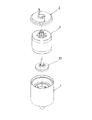
本発明の一実施例に係わるコアレスモータは、図1に示すように、マグネット7の内部に遊星歯車減速機を構成する。そして、図2に示すように、外筒・ギヤユニット1、モータ軸ユニット23、ロータユニット2、後蓋ユニット3の4つのユニットに分けて構成することで、以下に述べるように容易に組み立てることができる。
As shown in FIG. 1, the coreless motor according to one embodiment of the present invention forms a planetary gear reducer inside a
図3において、磁性体で作られた内部継鉄兼内歯車6の外周部にマグネット7を取り付け、マグネット7の外周部に外筒4を取り付けて界磁組を形成する。そして、着磁した後、出力軸5、太陽歯車9、遊星歯車8を組み込み、中蓋10を有するモータ軸ユニット23が取り付けられる外筒・ギヤユニット1を完成する。着磁は遊星ギヤユニット(出力軸5、太陽歯車9、遊星歯車8)を組み込んだ後に行うこともできる。内部継鉄兼内歯車6に内接する遊星歯車8は、磁界の安定のため非磁性体で構成することが望ましい。ここまでは従来の構造と同一である。
In FIG. 3, a
図4において、モータ軸ユニット23は、モータ軸13に一対の軸受(玉軸受)であるボールベアリング24、間座25を取り付けたものを、中蓋10の中心にある孔に取り付け、モータ軸13の出力側にピニオンギヤ12を取り付けて成る。上記モータ軸13に玉軸受を取り付けたものを中蓋10に取り付ける際、出力側軸受(図4中、下側のボールベアリング24)の外輪を突き当てで支承し、反出力側軸受(図4中、上側のボールベアリング24)の外輪をばね等で加圧しながら接着固定する。これにより、適切に予圧を付加された状態を保持できるため、モータ軸13を回転させた際の振れがほとんど発生しなくなる。
In FIG. 4, the
図5において、円板16に整流子17を取り付け、円筒状のコイル11を整流子片と電気的に接続した後、接着固定してロータユニット2を完成する。これにより、ロータユニット2は軸の無い状態で構成する。
In FIG. 5, a
図6において、後蓋21に、ブラシばね18、ブラシ22および端子19を取り付けることで、後蓋ユニット3を完成する。
In FIG. 6, the
上記の4つのユニットを精度よく組み立て(図1参照)、減速機付きコアレスモータを完成する。 Assemble the above four units with high precision (see FIG. 1) to complete a coreless motor with a reduction gear.
詳しくは、内部継鉄兼内歯車6の外周部に円筒状のマグネット7を取り付け、マグネット7の外周部に外筒4を取り付けて界磁組を形成する。そして、界磁組を着磁した後に出力軸5、減速機構(太陽歯車9、遊星歯車8)を組み込んで外筒・ギヤユニット1を構成する。また、モータ軸5に直列に間座を挟んで一対の玉軸受であるボールベアリング24を取り付ける。そして、中蓋10の孔に対し、モータ軸13の出力側のボールベアリング24の外輪を突き当てで支承し、反出力側のボールベアリング24の外輪を加圧しながら接着固定してモータ軸ユニット23を構成する。また、円板16に整流子17を取り付け、円筒形のコイル11を整流子17と電気的に接続した後に接着固定してロータユニット2を構成する。また、後蓋21に、ブラシばね18、ブラシ22および端子19を取り付けて後蓋ユニット3を構成する。
Specifically, a
そして、外筒・ギヤユニット1の内部継鉄兼内歯車6の内周部にモータ軸ユニット23の中蓋10の外周部を組み込み、次に、外筒4の内周部とマグネット7の外周部の間隙にロータユニット2のコイル11を組み込む。この時、コイル11、円板16、整流子17をモータ軸13に一体に回転するように取り付ける。次いで、ロータユニット2および外筒4に前記後蓋ユニット3を取り付けることでコアレスモータの組み立てが完了するようにしている。
Then, the outer peripheral part of the
上記のように、軸受(玉軸受)は一対のボールベアリング24とし、まずモータ軸13に対して間座25を挟んで2つ直列に軸受を取り付け、軸受外輪に予圧をかけた状態であらかじめ中蓋10の孔に組み込み、ユニット化(モータ軸ユニット23)しておく。そして、ユニット化されたモータ軸ユニット23を外筒・ギヤユニット1内の界磁組に対して精度よく支持しながら、中蓋10の外径部を内部継鉄兼内歯車6の内径部に組み付ける。
As described above, the bearings (ball bearings) are a pair of
図7等で述べたコアレスモータは、小型化は達成されているが、界磁組とモータ軸との間に介在する部品点数や組み立て工程が多いことなどから、界磁組とモータ軸を所望の精度で組み立てることは難しかった。しかし、上記実施例のように、モータ軸ユニット23を予め構成し、該モータ軸ユニット23を外筒・ギヤユニット1内の界磁組に直接組み付けるようにしているので、モータ軸13とマグネット7、外筒4との同軸精度を容易に確保できる。つまり、モータ軸13とマグネット7、外筒4との必要な同軸度を確保しやすく、組み立て作業が容易な構造のコアレスモータとなる。
Although the coreless motor described in FIG. 7 and the like has been reduced in size, the number of parts interposed between the field assembly and the motor shaft and the number of assembling processes are large, so the field assembly and the motor shaft are desired. It was difficult to assemble with precision. However, as in the above embodiment, the
以上に述べたのは、減速機構に遊星歯車減速機を採用した場合であるが、一般的な多段平歯車減速機や、3K型不思議歯車機構、波動歯車機構などを使用した場合でも同様の特徴をもった減速機構付きコアレスモータを構成することができる。 The above is a case where a planetary gear speed reducer is adopted as the speed reduction mechanism, but the same characteristics are obtained even when a general multi-stage spur gear speed reducer, a 3K type mysterious gear mechanism, a wave gear mechanism, or the like is used. A coreless motor with a speed reduction mechanism having the above can be configured.
1 外筒・ギヤユニット
2 ロータユニット
3 後蓋ユニット
4 外筒
5 出力軸
6 内部継鉄兼内歯車
7 界磁マグネット
8 遊星歯車
9 太陽歯車
10 中蓋
11 コイル
12 ピニオンギヤ
13 モータ軸
16 円板
17 整流子
18 ブラシばね
19 端子
21 後蓋
22 ブラシ
23 モータ軸ユニット
24 ボールベアリング
25 間座
DESCRIPTION OF
Claims (3)
前記内部継鉄に取り付けられる中蓋と、前記中蓋を前記内部継鉄に取り付けた際に、前記遊星ギヤユニットの遊星歯車と噛み合うピニオンギヤが取り付けられたモータ軸と、前記モータ軸を前記中蓋に対して回転可能に軸受けする一対の軸受とを含むモータ軸ユニットと、
前記モータ軸に取り付けられる円板と、前記円板に取り付けられる整流子と、前記円板に固定され、前記整流子と電気的に接続される円筒形のコイルとを含むロータユニットと、
前記外筒に取り付けられる後蓋と、前記後蓋に固定され、前記後蓋が前記外筒に取り付けられた際に、前記整流子と接触するブラシとを含む後蓋ユニットとを有し、
前記ピニオンギヤが前記遊星ギヤユニットの遊星歯車と噛み合うように前記中蓋を前記内部継鉄に取り付けた後、前記コイルが前記マグネットと前記外筒との間に位置するように前記モータ軸に前記円板を取り付け、その後、前記外筒に前記後蓋を取り付けることを特徴とするコアレスモータ。 A planetary gear unit, an internal yoke on which an internal gear meshing with the planetary gear of the planetary gear unit is formed, a cylindrical magnet disposed on the outer periphery of the inner yoke, and an outer surface disposed on the outer periphery of the magnet An outer cylinder / gear unit including a cylinder,
An inner lid attached to the inner yoke, a motor shaft to which a pinion gear that meshes with a planetary gear of the planetary gear unit when the inner lid is attached to the inner yoke, and the motor shaft to the inner lid A motor shaft unit including a pair of bearings rotatably bearing against the motor shaft unit;
A rotor unit including a disc attached to the motor shaft, a commutator attached to the disc, and a cylindrical coil fixed to the disc and electrically connected to the commutator ;
A back cover unit that includes a rear cover that is attached to the outer cylinder, and a brush that is fixed to the rear cover and includes a brush that contacts the commutator when the rear cover is attached to the outer cylinder ;
After the inner lid is attached to the inner yoke so that the pinion gear meshes with the planetary gear of the planetary gear unit, the motor shaft is placed on the circle so that the coil is positioned between the magnet and the outer cylinder. A coreless motor , wherein a plate is attached, and then the rear lid is attached to the outer cylinder .
前記モータ軸に取り付けられるピニオンギヤと、A pinion gear attached to the motor shaft;
前記ピニオンギヤと噛みあう遊星歯車を有する遊星ギヤユニットと、A planetary gear unit having a planetary gear meshing with the pinion gear;
前記遊星ギヤユニットの遊星歯車と噛みあう内歯車が形成される内部継鉄と、An internal yoke that forms an internal gear that meshes with the planetary gear of the planetary gear unit;
前記内部継鉄に固定される中蓋と、An inner lid fixed to the inner yoke;
前記中蓋に前記モータ軸を軸受けする一対の軸受と、A pair of bearings for bearing the motor shaft on the inner lid;
前記内部継鉄の外周に配置される円筒状のマグネットと、A cylindrical magnet disposed on the outer periphery of the internal yoke;
前記内部継鉄に固定され、前記マグネットの外周に配置される外筒と、An outer cylinder fixed to the inner yoke and disposed on the outer periphery of the magnet;
前記マグネットと前記外筒との間に配置され、通電されることで前記モータ軸を中心として、前記マグネットに対して回転するコイルと、A coil which is arranged between the magnet and the outer cylinder and rotates with respect to the magnet around the motor shaft by being energized;
前記コイルと電気的に接続される整流子と、A commutator electrically connected to the coil;
前記整流子が取り付けられ、前記コイルに固定される円板と、A disc to which the commutator is attached and fixed to the coil;
前記整流子と接触するブラシと、A brush in contact with the commutator;
前記ブラシが取り付けられ、前記外筒に固定される後蓋と、を有することを特徴とするコアレスモータ。A coreless motor, comprising: a rear lid attached to the brush and fixed to the outer cylinder.
Priority Applications (2)
| Application Number | Priority Date | Filing Date | Title |
|---|---|---|---|
| JP2008131737A JP5137683B2 (en) | 2008-05-20 | 2008-05-20 | Coreless motor |
| US12/464,313 US8004132B2 (en) | 2008-05-20 | 2009-05-12 | Coreless motor |
Applications Claiming Priority (1)
| Application Number | Priority Date | Filing Date | Title |
|---|---|---|---|
| JP2008131737A JP5137683B2 (en) | 2008-05-20 | 2008-05-20 | Coreless motor |
Publications (3)
| Publication Number | Publication Date |
|---|---|
| JP2009284584A JP2009284584A (en) | 2009-12-03 |
| JP2009284584A5 JP2009284584A5 (en) | 2011-06-23 |
| JP5137683B2 true JP5137683B2 (en) | 2013-02-06 |
Family
ID=41341554
Family Applications (1)
| Application Number | Title | Priority Date | Filing Date |
|---|---|---|---|
| JP2008131737A Active JP5137683B2 (en) | 2008-05-20 | 2008-05-20 | Coreless motor |
Country Status (2)
| Country | Link |
|---|---|
| US (1) | US8004132B2 (en) |
| JP (1) | JP5137683B2 (en) |
Families Citing this family (17)
| Publication number | Priority date | Publication date | Assignee | Title |
|---|---|---|---|---|
| IL195613A0 (en) | 2008-11-30 | 2009-09-01 | S P F Productions Ltd | Compact gear motor assembly |
| US8267218B2 (en) * | 2009-10-16 | 2012-09-18 | Yuan-Hsiang Huang | Power operated steering assisting device for vehicles |
| US8820448B2 (en) * | 2010-07-02 | 2014-09-02 | M-Link Co., Ltd. | In-wheel motor and electrically driven vehicle |
| TWI455448B (en) * | 2012-05-16 | 2014-10-01 | Ting Hung Su | High torque planetary magnetic motors |
| JP5506858B2 (en) * | 2012-05-30 | 2014-05-28 | 三菱電機株式会社 | Rotating electric machine |
| US8834311B1 (en) * | 2013-03-07 | 2014-09-16 | The United States Of America As Represented By The Secretary Of The Army | Concentric electric servomotor/gearbox drive |
| JP2015108305A (en) * | 2013-12-03 | 2015-06-11 | 日本電産コパル株式会社 | Coreless motor for throttle control device, manufacturing method of coreless motor for throttle control device, and throttle control device |
| CN109525067A (en) * | 2014-10-07 | 2019-03-26 | 日本电产三协株式会社 | The control method of brushless motor |
| JP2017036825A (en) * | 2015-08-07 | 2017-02-16 | 日本電産サンキョー株式会社 | Planetary gear speed reducer and drive mechanism |
| WO2017221506A1 (en) * | 2016-06-21 | 2017-12-28 | 株式会社エムリンク | Coreless motor |
| KR102346059B1 (en) * | 2016-06-21 | 2021-12-31 | 코어레스 모터 가부시키가이샤 | coreless motor |
| WO2019123666A1 (en) * | 2017-12-22 | 2019-06-27 | 株式会社シンクテック | Coreless motor |
| WO2019124543A1 (en) * | 2017-12-22 | 2019-06-27 | 株式会社シンクテック | Coreless motor |
| CN207994817U (en) * | 2018-02-11 | 2018-10-19 | 广东美的生活电器制造有限公司 | Motor and cooking machine |
| CN110266145A (en) * | 2019-05-31 | 2019-09-20 | 杭州威仕达机电科技有限公司 | The drive mechanism of drag cup tube shaped electric machine |
| JP7127847B2 (en) * | 2019-06-26 | 2022-08-30 | コアレスモータ株式会社 | coreless motor |
| FR3110656B1 (en) * | 2020-05-19 | 2022-06-10 | Bontaz Centre R&D | GEAR MOTOR COMPRISING A DOUBLE DIAMETER STATOR. |
Family Cites Families (14)
| Publication number | Priority date | Publication date | Assignee | Title |
|---|---|---|---|---|
| CA1204210A (en) * | 1981-10-27 | 1986-05-06 | Hisao Kinjo | Recording and/or reproducing apparatus |
| JPS59103556A (en) * | 1982-11-30 | 1984-06-15 | Matsushita Electric Works Ltd | Coreless motor |
| JPH0428214Y2 (en) * | 1985-12-28 | 1992-07-08 | ||
| JPS63194211A (en) * | 1987-02-09 | 1988-08-11 | Sony Corp | Lens driving device for camera |
| JP2607889B2 (en) * | 1987-08-04 | 1997-05-07 | 光洋精工株式会社 | Reduction motor |
| JP3120185B2 (en) * | 1991-07-16 | 2000-12-25 | セイコーインスツルメンツ株式会社 | Coreless motor |
| JPH08186955A (en) * | 1994-12-29 | 1996-07-16 | Sayama Precision Ind Co | Motor with built-in speed reducer |
| JP3338244B2 (en) * | 1995-08-18 | 2002-10-28 | 三菱電機株式会社 | Planetary gear reduction mechanism |
| JPH1175339A (en) * | 1997-08-29 | 1999-03-16 | Matsushita Electric Ind Co Ltd | Spindle motor |
| JP2001339914A (en) * | 2000-05-24 | 2001-12-07 | Namiki Precision Jewel Co Ltd | Dc coreless motor |
| JP2002314846A (en) * | 2001-04-09 | 2002-10-25 | Toshiba Corp | Imaging unit and drive unit |
| US7118506B2 (en) * | 2004-08-06 | 2006-10-10 | Visteon Global Technologies, Inc. | Actuator for active front steering system |
| JP4789279B2 (en) * | 2005-04-28 | 2011-10-12 | 並木精密宝石株式会社 | Motor shaft and micro motor for micro motor |
| JP2007252174A (en) * | 2006-02-15 | 2007-09-27 | Venera Laboratory Co Ltd | Geared motor and planetary geared dynamo |
-
2008
- 2008-05-20 JP JP2008131737A patent/JP5137683B2/en active Active
-
2009
- 2009-05-12 US US12/464,313 patent/US8004132B2/en active Active
Also Published As
| Publication number | Publication date |
|---|---|
| US8004132B2 (en) | 2011-08-23 |
| JP2009284584A (en) | 2009-12-03 |
| US20090289514A1 (en) | 2009-11-26 |
Similar Documents
| Publication | Publication Date | Title |
|---|---|---|
| JP5137683B2 (en) | Coreless motor | |
| JP2006234005A (en) | Motor-incorporated hypocycloid-type speed reducer | |
| JP4727467B2 (en) | motor | |
| KR20200100683A (en) | Compact gear motor | |
| JP4557754B2 (en) | Pump motor | |
| JP4600886B2 (en) | motor | |
| JP2012029350A (en) | Brushless motor | |
| JP4543709B2 (en) | Axial gap rotating electric machine | |
| CN105745420A (en) | Coreless motor for throttle controlling devices, manufacturing method for coreless motor for throttle controlling devices, and throttle control device | |
| JP2006304558A (en) | Hypocycloid speed reducer built in motor | |
| CN108352760B (en) | Gear motor and method for manufacturing gear motor | |
| JP6589215B1 (en) | Coreless motor | |
| JP2021105408A (en) | Geared motor | |
| US3146363A (en) | Electric motor and method of making same | |
| JP2016174512A (en) | Dynamo-electric machine and method of manufacturing dynamo-electric machine | |
| JP2009296828A (en) | Motor device with decelerator | |
| CN211089426U (en) | Permanent magnet linear stepping motor | |
| JP6209060B2 (en) | Inductor type motor | |
| JP2016098989A (en) | Assembling method of motor built-in type decelerator and motor built-in type decelerator | |
| JP5969330B2 (en) | Rotor and motor | |
| JP2018129933A (en) | Motor and method for manufacturing motor | |
| JP2007014166A (en) | Stepping motor | |
| JP2015080306A (en) | Inner rotor type motor | |
| JP2003299331A (en) | Shaft-fixed motor having gear, and gear head | |
| JP2019122084A (en) | Rotor for motor and motor |
Legal Events
| Date | Code | Title | Description |
|---|---|---|---|
| RD03 | Notification of appointment of power of attorney |
Free format text: JAPANESE INTERMEDIATE CODE: A7423 Effective date: 20100602 |
|
| RD04 | Notification of resignation of power of attorney |
Free format text: JAPANESE INTERMEDIATE CODE: A7424 Effective date: 20100603 |
|
| A521 | Written amendment |
Free format text: JAPANESE INTERMEDIATE CODE: A523 Effective date: 20110502 |
|
| A621 | Written request for application examination |
Free format text: JAPANESE INTERMEDIATE CODE: A621 Effective date: 20110502 |
|
| TRDD | Decision of grant or rejection written | ||
| A01 | Written decision to grant a patent or to grant a registration (utility model) |
Free format text: JAPANESE INTERMEDIATE CODE: A01 Effective date: 20121016 |
|
| A01 | Written decision to grant a patent or to grant a registration (utility model) |
Free format text: JAPANESE INTERMEDIATE CODE: A01 |
|
| A977 | Report on retrieval |
Free format text: JAPANESE INTERMEDIATE CODE: A971007 Effective date: 20121017 |
|
| A61 | First payment of annual fees (during grant procedure) |
Free format text: JAPANESE INTERMEDIATE CODE: A61 Effective date: 20121113 |
|
| R150 | Certificate of patent or registration of utility model |
Ref document number: 5137683 Country of ref document: JP Free format text: JAPANESE INTERMEDIATE CODE: R150 Free format text: JAPANESE INTERMEDIATE CODE: R150 |
|
| FPAY | Renewal fee payment (event date is renewal date of database) |
Free format text: PAYMENT UNTIL: 20151122 Year of fee payment: 3 |