JP6604749B2 - Vibration type motor, lens driving device using the vibration type motor, lens unit, and imaging device - Google Patents
Vibration type motor, lens driving device using the vibration type motor, lens unit, and imaging device Download PDFInfo
- Publication number
- JP6604749B2 JP6604749B2 JP2015110460A JP2015110460A JP6604749B2 JP 6604749 B2 JP6604749 B2 JP 6604749B2 JP 2015110460 A JP2015110460 A JP 2015110460A JP 2015110460 A JP2015110460 A JP 2015110460A JP 6604749 B2 JP6604749 B2 JP 6604749B2
- Authority
- JP
- Japan
- Prior art keywords
- type motor
- vibration type
- contact
- friction member
- vibrator
- Prior art date
- Legal status (The legal status is an assumption and is not a legal conclusion. Google has not performed a legal analysis and makes no representation as to the accuracy of the status listed.)
- Active
Links
- 238000003384 imaging method Methods 0.000 title claims description 5
- 238000003825 pressing Methods 0.000 claims description 6
- 230000000694 effects Effects 0.000 description 17
- 238000000034 method Methods 0.000 description 14
- 230000008859 change Effects 0.000 description 13
- 238000010586 diagram Methods 0.000 description 11
- 230000003287 optical effect Effects 0.000 description 7
- 230000033001 locomotion Effects 0.000 description 6
- 230000009467 reduction Effects 0.000 description 6
- 230000005540 biological transmission Effects 0.000 description 5
- 230000008878 coupling Effects 0.000 description 5
- 238000010168 coupling process Methods 0.000 description 5
- 238000005859 coupling reaction Methods 0.000 description 5
- 238000009826 distribution Methods 0.000 description 5
- 238000005096 rolling process Methods 0.000 description 5
- 230000007423 decrease Effects 0.000 description 4
- 238000005452 bending Methods 0.000 description 3
- 230000007246 mechanism Effects 0.000 description 3
- 239000002184 metal Substances 0.000 description 2
- 238000007665 sagging Methods 0.000 description 2
- 230000003746 surface roughness Effects 0.000 description 2
- 230000009471 action Effects 0.000 description 1
- 230000006835 compression Effects 0.000 description 1
- 238000007906 compression Methods 0.000 description 1
- 230000008602 contraction Effects 0.000 description 1
- 230000005489 elastic deformation Effects 0.000 description 1
- 238000004519 manufacturing process Methods 0.000 description 1
- 239000007769 metal material Substances 0.000 description 1
- 238000000465 moulding Methods 0.000 description 1
- 230000004044 response Effects 0.000 description 1
- 238000000926 separation method Methods 0.000 description 1
- 238000003466 welding Methods 0.000 description 1
Images


Classifications
-
- G—PHYSICS
- G02—OPTICS
- G02B—OPTICAL ELEMENTS, SYSTEMS OR APPARATUS
- G02B7/00—Mountings, adjusting means, or light-tight connections, for optical elements
- G02B7/02—Mountings, adjusting means, or light-tight connections, for optical elements for lenses
- G02B7/04—Mountings, adjusting means, or light-tight connections, for optical elements for lenses with mechanism for focusing or varying magnification
- G02B7/08—Mountings, adjusting means, or light-tight connections, for optical elements for lenses with mechanism for focusing or varying magnification adapted to co-operate with a remote control mechanism
-
- G—PHYSICS
- G03—PHOTOGRAPHY; CINEMATOGRAPHY; ANALOGOUS TECHNIQUES USING WAVES OTHER THAN OPTICAL WAVES; ELECTROGRAPHY; HOLOGRAPHY
- G03B—APPARATUS OR ARRANGEMENTS FOR TAKING PHOTOGRAPHS OR FOR PROJECTING OR VIEWING THEM; APPARATUS OR ARRANGEMENTS EMPLOYING ANALOGOUS TECHNIQUES USING WAVES OTHER THAN OPTICAL WAVES; ACCESSORIES THEREFOR
- G03B3/00—Focusing arrangements of general interest for cameras, projectors or printers
- G03B3/10—Power-operated focusing
-
- G—PHYSICS
- G03—PHOTOGRAPHY; CINEMATOGRAPHY; ANALOGOUS TECHNIQUES USING WAVES OTHER THAN OPTICAL WAVES; ELECTROGRAPHY; HOLOGRAPHY
- G03B—APPARATUS OR ARRANGEMENTS FOR TAKING PHOTOGRAPHS OR FOR PROJECTING OR VIEWING THEM; APPARATUS OR ARRANGEMENTS EMPLOYING ANALOGOUS TECHNIQUES USING WAVES OTHER THAN OPTICAL WAVES; ACCESSORIES THEREFOR
- G03B5/00—Adjustment of optical system relative to image or object surface other than for focusing
-
- H—ELECTRICITY
- H02—GENERATION; CONVERSION OR DISTRIBUTION OF ELECTRIC POWER
- H02N—ELECTRIC MACHINES NOT OTHERWISE PROVIDED FOR
- H02N2/00—Electric machines in general using piezoelectric effect, electrostriction or magnetostriction
- H02N2/0005—Electric machines in general using piezoelectric effect, electrostriction or magnetostriction producing non-specific motion; Details common to machines covered by H02N2/02 - H02N2/16
- H02N2/005—Mechanical details, e.g. housings
- H02N2/0065—Friction interface
-
- H—ELECTRICITY
- H02—GENERATION; CONVERSION OR DISTRIBUTION OF ELECTRIC POWER
- H02N—ELECTRIC MACHINES NOT OTHERWISE PROVIDED FOR
- H02N2/00—Electric machines in general using piezoelectric effect, electrostriction or magnetostriction
- H02N2/02—Electric machines in general using piezoelectric effect, electrostriction or magnetostriction producing linear motion, e.g. actuators; Linear positioners ; Linear motors
- H02N2/026—Electric machines in general using piezoelectric effect, electrostriction or magnetostriction producing linear motion, e.g. actuators; Linear positioners ; Linear motors by pressing one or more vibrators against the driven body
-
- G—PHYSICS
- G03—PHOTOGRAPHY; CINEMATOGRAPHY; ANALOGOUS TECHNIQUES USING WAVES OTHER THAN OPTICAL WAVES; ELECTROGRAPHY; HOLOGRAPHY
- G03B—APPARATUS OR ARRANGEMENTS FOR TAKING PHOTOGRAPHS OR FOR PROJECTING OR VIEWING THEM; APPARATUS OR ARRANGEMENTS EMPLOYING ANALOGOUS TECHNIQUES USING WAVES OTHER THAN OPTICAL WAVES; ACCESSORIES THEREFOR
- G03B2205/00—Adjustment of optical system relative to image or object surface other than for focusing
- G03B2205/0053—Driving means for the movement of one or more optical element
- G03B2205/0061—Driving means for the movement of one or more optical element using piezoelectric actuators
Description
本発明は、交流電圧を印加することで振動する振動子を用いる振動型モータに関する。 The present invention relates to a vibration type motor using a vibrator that vibrates by applying an AC voltage.
圧電素子の超音波振動を利用した振動型モータは、小型で、高い駆動力が得られ、広い速度レンジに対応でき、低振動かつ低騒音であるという特徴を有している。これらの特徴により、振動型モータは例えば小型かつ高出力な駆動が求められるカメラのレンズ鏡筒内において、フォーカスレンズの直線駆動やカム筒の回転駆動に用いられている。 A vibration type motor using ultrasonic vibrations of a piezoelectric element is characterized by being small in size, capable of obtaining a high driving force, compatible with a wide speed range, low vibration and low noise. Due to these characteristics, the vibration type motor is used for linear drive of the focus lens and rotational drive of the cam cylinder in a lens barrel of a camera that is required to be driven with a small size and high output.
振動型モータの駆動原理としては、圧電効果による圧電素子の伸縮を用いて振動子を振動させ、その振動を振動子に圧接された摩擦部材に伝達することで摩擦部材を相対的に駆動するものが知られている。特許文献1に開示された装置は振動型モータの一例である。
The driving principle of the vibration type motor is that the vibrator is vibrated using the expansion and contraction of the piezoelectric element due to the piezoelectric effect, and the friction member is relatively driven by transmitting the vibration to the friction member pressed against the vibrator. It has been known. The device disclosed in
特許文献1に開示された装置は、突起が設けられた平板状の振動子に複数の振動モードを発生させ、振動モードの組み合わせにより突起に楕円運動を発生させる振動型モータである。突起は摩擦部材と圧接されており、突起に楕円運動が発生すると、突起は摩擦部材と接触と離間を繰り返しながら摩擦部材を送り出す。これにより、摩擦部材は振動子に対して相対的に駆動される。
The device disclosed in
この時、摩擦部材の共振周波数が振動子を振動させる駆動周波数帯と重なると、摩擦部材の共振が誘発されて不要な振動が発生し、駆動力の低下や騒音が発生する。この課題に対して、特許文献2では摩擦部材の共振周波数を特定の範囲内に収め、振動子の駆動周波数帯と摩擦部材の共振周波数が重ならないように設計することを提案している。
At this time, if the resonance frequency of the friction member overlaps with a drive frequency band that vibrates the vibrator, resonance of the friction member is induced to generate unnecessary vibration, resulting in a decrease in driving force and noise. In response to this problem,
摩擦部材の共振周波数が特定の範囲内に収まるように設計した場合でも、部品寸法や固定方法の僅かなバラつきにより、摩擦部材の共振周波数は変化してしまう。このため、摩擦部材の共振周波数を特定の範囲内に収め、駆動周波数帯と重ならないように設計された場合でも、製作された実物においては摩擦部材の共振周波数が振動子を振動させる駆動周波数帯と重なり、駆動力の低下や騒音が発生することがあった。 Even when the resonance frequency of the friction member is designed to fall within a specific range, the resonance frequency of the friction member changes due to slight variations in component dimensions and fixing method. For this reason, even in the case where the resonance frequency of the friction member is designed to be within a specific range and does not overlap with the drive frequency band, in the manufactured product, the resonance frequency of the friction member causes the vibrator to vibrate. In some cases, the driving force is reduced and noise is generated.
特に摩擦部材をプレス成形といったコストの低い製造法で製造する場合は、摩擦部材の角部の形状を安定させることは困難であり、摩擦部材の共振周波数を特定の範囲内に収められず駆動力の低下や騒音が発生し易かった。 In particular, when the friction member is manufactured by a low-cost manufacturing method such as press molding, it is difficult to stabilize the shape of the corner of the friction member, and the resonance frequency of the friction member cannot be kept within a specific range. It was easy for noise reduction and noise to occur.
そこで、本発明の目的は、部品寸法や固定方法のバラつきによる摩擦部材の共振周波数の変化が低減され、駆動力の低下や騒音が発生しにくい振動型モータ及び振動型モータを用いたレンズ駆動装置を提供することである。 SUMMARY OF THE INVENTION Accordingly, an object of the present invention is to reduce a change in the resonance frequency of the friction member due to variations in component dimensions and fixing methods, and to reduce a driving force and to prevent noise, and a lens driving device using the vibration type motor. Is to provide.
上記課題を解決するために、本発明に係る振動型モータは、
交流電圧を印加することで振動する振動子と、
前記振動子と圧接する第1の面と、前記第1の面の反対側に位置する第2の面を有し所定の方向に延在する摩擦部材と
前記摩擦部材を保持する保持部材を備えた振動型モータであって、
前記第1の面は隣接する面との間に前記所定の方向と平行な方向に延在する第1の角部を形成し、
前記第2の面は隣接する面との間に前記所定の方向と平行な方向に延在する第2の角部を形成し、
前記第1の角部と前記第2の角部の曲率半径は異なり、
前記第1の角部と前記第2の角部のうち曲率半径が小さい角部を形成する前記第1の面と前記第2の面のいずれか一つの面が前記保持部材と接触することを特徴とする。
In order to solve the above problems, a vibration type motor according to the present invention is:
A vibrator that vibrates by applying an alternating voltage;
A first member that is in pressure contact with the vibrator; a second member that is positioned opposite to the first member; and a friction member that extends in a predetermined direction; and a holding member that holds the friction member. Vibration motor,
The first surface forms a first corner extending in a direction parallel to the predetermined direction between adjacent surfaces,
The second surface forms a second corner extending in a direction parallel to the predetermined direction between adjacent surfaces,
The curvature radii of the first corner and the second corner are different,
Of the first corner and the second corner, any one of the first surface and the second surface forming a corner having a small radius of curvature is in contact with the holding member. Features.
本発明によれば、部品寸法や固定方法のバラつきによる摩擦部材の共振周波数の変化が低減され、駆動力の低下や騒音が発生しにくい振動型モータ及び振動型モータを用いたレンズ駆動装置を提供することができる。 According to the present invention, there are provided a vibration type motor and a lens driving device using the vibration type motor, in which changes in the resonance frequency of the friction member due to variations in component dimensions and fixing methods are reduced, and driving force and noise are less likely to occur. can do.
本発明を適用した基本的な実施形態を、添付図面を参照して以下、具体的に説明する。尚、図面において同一部分は同一符号で示してある。以下説明する実施形態は例示として説明するものであり、本発明を限定するものではないことは言うまでもない。 A basic embodiment to which the present invention is applied will be specifically described below with reference to the accompanying drawings. In the drawings, the same parts are denoted by the same reference numerals. It is needless to say that the embodiments described below are described as examples and do not limit the present invention.
(第1の実施形態)
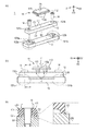
まず、本発明の第1の実施形態にかかる振動型モータ1の構成と特徴について詳細に説明する。図1は本発明の第1の実施形態にかかる振動型モータ1を示す図である。図1(a)は、振動型モータ1の分解斜視図、図1(b)は振動型モータ1を駆動方向(図1においてD1方向)の側面方向(図1においてD2方向)より見た図、図1(c)は図1(b)のA−A線に沿った断面図である。
(First embodiment)
First, the configuration and characteristics of the
図1(a)及び図1(b)に示すように振動型モータ1は、振動子11、摩擦部材12、保持部材13、締結部材14によって構成される。
As shown in FIGS. 1A and 1B, the
振動子11は電圧を印加することで伸縮する圧電素子111と弾性体112によって構成される。圧電素子111に適切な交流電圧を印加することで振動子11が振動する。弾性体112には、後述の摩擦部材12方向に突出する突起112aが設けられており、振動子11が振動した時には突起112aが図1(b)においてr1で示す楕円運動を描く。交流電圧の印加方法や、突起の楕円運動の発生原理については特許文献1に開示されているものと同様であるため、省略する。
The
振動子11は不図示の加圧手段により加圧力F1を受け、突起112aは摩擦部材12と圧接している。摩擦部材12は図1においてD1方向に延在する直方体形状の部材である。突起112aが摩擦部材12と圧接した状態で突起112aに楕円運動を発生させると、突起112aが摩擦部材12に繰り返し摩擦力を与える。この摩擦力により摩擦部材12が相対的に駆動される。この時、摩擦部材12の位置を固定した場合、振動子11は図1中におけるD1方向に移動する。反対に、振動子11の位置を固定した場合、摩擦部材12が図1中におけるD1方向に移動する。また、摩擦部材12には固定用の穴部121a、121bが設けられている。
The
保持部材13は摩擦部材12を保持する部材であり、2つの固定部131a、131bを有している。また、固定部131a、131bには摩擦部材12と接触する接触面132a、132bが形成されている。
The
締結部材14であるビスは、摩擦部材12の穴部121a、121bを介して保持部材13の固定部131a、131bに嵌合する。これにより摩擦部材12を保持部材13に締結することができる。
The screws that are the fastening
ここで、摩擦部材12としては例えば硬度の高い金属材を用いることができる。さらに、摩擦部材12を図1においてD1方向に延在する直方体形状を形成するには、例えばプレス加工が用いられる。このようにすることで、摩擦部材12を低コストで製造できる。この時、加工の方向によってダレやバリが発生し、直方体形状の摩擦部材12の角部は異なった曲率半径を有する。ここで、摩擦部材12のうち、振動子11の突起112aが圧接する面を第1の面S1、第1の面S1の反対側に位置する面を第2の面S2とする。さらに、第1の面S1と第1の面S1に隣接する面の間に形成され、摩擦部材12の延在する所定の方向(図1においてD1方向)と平行な方向に延在する角部を第1の角部C1とする。また、第2の面S2と第2の面S2に隣接する面の間に形成され、摩擦部材12の延在する所定の方向(図1においてD1方向)と平行な方向に延在する角部を第2の角部C2とする。
Here, as the
図1(c)は図1(b)のA−A線に沿った断面図であり、第1の角部C1と第2の角部C2の詳細を示している。 FIG.1 (c) is sectional drawing along the AA line of FIG.1 (b), and has shown the detail of the 1st corner | angular part C1 and the 2nd corner | angular part C2.
第1の角部C1の曲率半径をR1、第2の角部C2の曲率半径をR2とした時、R1よりR2の方が小さい。振動型モータ1の特徴は、第1の角部C1の曲率半径R1と第2の角部の曲率半径R2の大きさが異なることである。また、第1の角部C1と第2の角部C2のうち曲率半径の小さい第2の角部C2を形成する第2の面S2が保持部材13の接触面132a、132bと接触することである。この特徴の作用および効果については後述する。
When the radius of curvature of the first corner C1 is R1, and the radius of curvature of the second corner C2 is R2, R2 is smaller than R1. The characteristic of the
次に、本発明の第1の実施形態にかかる振動型モータ1の作用について述べる。
Next, the operation of the
図2(a)、図2(b)及び図2(c)は、それぞれ図1(c)と同様の断面図である。図2(a)は上述の振動型モータ1の特徴を備えない場合を説明する図であり、図2(b)及び図2(c)は上述の振動型モータ1の特徴を備えた場合を説明する図である。図2(a)は例えばプレス加工によりダレやバリが発生した摩擦部材12においてダレ面が保持部材13と接触するよう固定した場合を示す図である。図2(b)は例えばプレス加工によりダレやバリが発生した摩擦部材12においてバリ面が保持部材13と接触するよう固定した場合を示す図である。図2(c)は例えばプレス加工の後にバレル加工などのバリを落とす加工を施した摩擦部材12をダレ面の反対側の面が保持部材13と接触するよう固定した場合を示す図である。
2 (a), 2 (b), and 2 (c) are cross-sectional views similar to FIG. 1 (c), respectively. FIG. 2A is a diagram for explaining a case where the above-described
図2(a)では、第1の角部C1の曲率半径R1は第2の角部C2の曲率半径R2よりも小さい。しかし、第1の角部C1と第2の角部C2のうち曲率半径の小さい第1の角部C1を形成する第1の面S1ではなく、第2の面S2が保持部材13と接触している。
In FIG. 2A, the radius of curvature R1 of the first corner C1 is smaller than the radius of curvature R2 of the second corner C2. However, the second surface S2 comes into contact with the holding
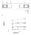
特許文献2に記載の装置のように、摩擦部材12は共振周波数が所定の範囲内に収まり、振動子11が振動する駆動周波数と重ならないように設計される。しかし、部品寸法や固定方法のバラつきにより共振周波数が設計値から変化してしまうことがある。図2(a)のように保持部材13と接触する第2の面S2が大きな曲率半径の第2の角部C2を有する場合、摩擦部材12と保持部材13との接触範囲の幅W1が小さくなる。また、曲率半径R2を厳密に管理することは難しく、接触範囲の幅W1は変動しやすい。摩擦部材12と保持部材13との接触範囲の幅W1が変化した際の摩擦部材12の共振周波数の変化を有限要素法(Finite Element Method:FEM)を用いて解析した結果を図5に示す。
Like the device described in
図5(a)は摩擦部材12のFEM解析条件を表す図である。図5(a)の斜線部A1は摩擦部材12と保持部材13の接触面132a、132bとの接触範囲を表す。また、摩擦部材12と保持部材13との接触範囲の幅を小さくした時の振動モードの共振周波数の変化を図5(b)に示す。図5(b)においてM1、M3、M5で表す実線はそれぞれ摩擦部材12の屈曲1次振動モード、屈曲2次振動モード、屈曲3次振動モードの共振周波数の変化を表している。また、図5(b)においてM2、M4、M6で表す破線はそれぞれ摩擦部材12の捻じり1次振動モード、捻じり2次振動モード、捻じり3次振動モードの共振周波数の変化を表している。図5(b)に示すように、M1からM6で表すいずれの振動モードにおいても接触範囲の幅W1が小さくなると共振周波数が低下する傾向がある。以上のFEM解析結果により、図2(a)に示すように接触範囲の幅W1が変動しやすい場合は摩擦部材12の共振周波数が大きく変化しやすいことが分かる。
FIG. 5A is a diagram illustrating FEM analysis conditions for the
図2(b)及び図2(c)では、図2(a)の場合と異なり、第1の角部C1の曲率半径R1は第2の角部C2の曲率半径R2よりも大きい。そして、第1の角部C1と第2の角部C2のうち曲率半径の小さい第2の角部C2を形成する第2の面S2が保持部材13と接触している。図2(b)ではバリによる凸部のみが保持部材13に接触するため接触面積は少ないが、接触範囲の幅W1は図2(a)より広く得ることができる。また、図2(c)ではほぼ全域が接触範囲となるため接触範囲の幅W1は図2(a)より広く得ることができる。また、第2の角部C2の曲率半径R2は小さく、曲率半径R2の変動が接触範囲の幅W1に与える影響は小さい。図5(b)に示すFEM解析結果より、図2(b)及び図2(c)に示すように接触範囲の幅W1が変動しにくい場合は摩擦部材12の共振周波数が変化しにくいことが分かる。
2 (b) and 2 (c), unlike the case of FIG. 2 (a), the radius of curvature R1 of the first corner C1 is larger than the radius of curvature R2 of the second corner C2. The second surface S <b> 2 that forms the second corner C <b> 2 having a small radius of curvature among the first corner C <b> 1 and the second corner C <b> 2 is in contact with the holding
以下、本発明の第1の実施形態にかかる振動型モータ1から得られる効果について説明する。
Hereinafter, effects obtained from the
図6は摩擦部材12の共振周波数の分布を示す図である。図6(a)及び図6(b)では、図5(b)で示した振動モードM1乃至M6の共振周波数の分布を表している。図6(a)は図2(a)で示したように接触範囲の幅W1の変動が大きく、共振周波数が大きく変化した場合の摩擦部材12の共振周波数の分布を示す。また、図6(b)は図2(b)及び図2(c)で示したように接触範囲の幅W1の変動が小さく、共振周波数の変化が小さい場合の摩擦部材12の共振周波数の分布を示す。摩擦部材12の共振周波数の設定値を破線で表し、共振周波数が接触範囲の幅W1の変動により変化した後の値を実線で表す。また、振動子11を振動させる駆動周波数帯をfdとする。
FIG. 6 is a diagram showing the distribution of the resonance frequency of the
特許文献2に開示された装置のように、摩擦部材12の共振周波数は振動子11の駆動周波数帯fdと重ならないように設定される。図6(a)に示すように摩擦部材12の共振周波数の変化が大きい場合は駆動周波数帯fdと摩擦部材12の共振周波数が重なってしまうことがある。これにより摩擦部材12の共振が誘発されて不要な振動が発生し、駆動力の低下や騒音が発生することがある。これに対し、図6(b)に示すように摩擦部材12の共振周波数の低下が小さい場合は振動子11の駆動周波数帯fdと摩擦部材12の共振周波数が重ならず、駆動力の低下や騒音の発生を抑制することができる。
As in the device disclosed in
以上により、第1の角部C1と第2の角部C2の曲率半径は異なり、第1の角部C1と第2の角部C2のうち角の曲率半径が小さい角部を形成する第1の面S1と第2の面S2のいずれか一つの面が保持部材13と接触する。これにより、部品寸法や固定方法のバラつきによる摩擦部材12の共振周波数の変化が低減され、駆動力の低下や騒音が発生しにくい振動型モータ1を提供することができる。
As described above, the first corner C1 and the second corner C2 have different curvature radii, and the first corner C1 and the second corner C2 form a corner having a smaller corner radius of curvature. Any one of the surface S1 and the second surface S2 is in contact with the holding
なお、第1の実施形態にかかる振動型モータ1では、第1の面S1が形成する第1の角部C1の曲率半径R1よりも第2の面S2が形成する第2の角部C2の曲率半径R2が小さい。ここでは、曲率半径が小さい角部を形成する第2の面S2が保持部材13と接触する例を示した。しかし、本発明は上記に限らず、第1の角部C1と第2の角部C2のうち曲率半径が小さい角部を形成する第1の面S1と第2の面S2のいずれか一つの面が保持部材13と接触すれば本発明の効果を得ることができる。例えば、第1の角部C1の曲率半径R1が第2の角部の曲率半径R2より小さい時は第1の面S1が保持部材13と接触すれば良い。
In the
なお、第1の実施形態にかかる振動型モータ1では、摩擦部材12をプレス加工で成形することで第1の角部C1の曲率半径R1と第2の角部C2の曲率半径R2が異なる形状となる例を示した。しかし、本発明の摩擦部材12の成形方法はプレス加工に限らず、第1の角部C1の曲率半径R1と第2の角部C2の曲率半径R2が異なれば、本発明の効果を得ることができる。このため、部品寸法や固定方法のバラつきによる摩擦部材12の共振周波数の変化が低減され、駆動力の低下や騒音が発生しにくい振動型モータ1を提供することができる。
In the
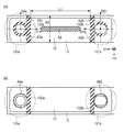
ここで、保持部材13の接触面132a、132bの形状と締結部材14の摩擦部材12と接触する面の形状について図4を用いて説明する。図4は摩擦部材12と保持部材13を保持部材13の接触面132a、132bに直交する方向から見た図である。摩擦部材12において振動子11の突起112aが摩擦摺動する領域を摺動領域A3とする。また、それぞれの固定部131a、131bから見て摩擦部材12が延在する方向を第1の方向D1a、D1bとする。さらに、それぞれの固定部131a、131bにおいて、接触面132a、132b上における第1の方向D1a、D1bと直交する方向を第2の方向D2a、D2bとする。振動型モータ1では、それぞれの固定部131a、131bが有する接触面132a、132bの第2の方向D2a、D2bの長さが図4(a)においてW2で示すように第1の方向D1a、D1b方向の摺動領域A3が存在する側の端部で最大となる。
Here, the shape of the
本発明の振動型モータ1は図2(b)及び図2(c)で示したように摩擦部材12と保持部材13の接触範囲の幅W1が大きく、変動しにくい。そして摩擦部材12の幅方向端部で確実に摩擦部材12と保持部材13が接触する作用を持つ。ここで、図4(a)に示すように接触面132a、132bは第2の方向D2a、D2bの長さが図4(a)においてW2で示すように第1の方向D1a、D1b方向の摺動領域A3が存在する側の端部で最大となる形状である。この時、図4(a)に示すように、摩擦部材12と接触面132a、132bは、摩擦部材12の幅方向の両端部にある領域A2a及びA2bで確実に接触することができる。
As shown in FIGS. 2B and 2C, the
また、領域A2a、A2bはそれぞれ固定部131a、131bから見て第1の方向D1a、D1b方向の摺動領域A3が存在する側の端部に配置されている。この時、摩擦部材12のうち固定されず自由に振動できる領域の長さは図4(a)においてL1で表され、領域A2a、A2bの間隔と一致する。領域A2a、A2bは摩擦部材12と保持部材13が摩擦部材12の角部の影響を受けず確実に接触する領域であるため、L1は変動しにくい。
The regions A2a and A2b are arranged at the end portions on the side where the sliding regions A3 in the first direction D1a and D1b direction exist as viewed from the fixing
摩擦部材12の共振周波数は自由に振動できる領域の長さL1にも依存するが、振動型モータ1では長さL1も変動しにくい。このため、部品寸法や固定方法のバラつきによる摩擦部材12の共振周波数の変化がより低減され、駆動力の低下や騒音が発生しにくい。以上により、それぞれの固定部131a、131bが有する接触面132a、132bは、第2の方向D2a、D2bの長さが第1の方向D1a、D1bの摺動領域A3が存在する側の端部で最大となることが好ましい。
The resonance frequency of the
また、保持部材13の接触面132a、132bの形状と締結部材14と摩擦部材12とが圧接する領域との関係を、図4(b)を用いて説明する。図4(b)は締結部材14と摩擦部材12とが圧接する領域A4a、A4bを図4(a)に投影した図である。振動型モータ1では領域A4a、A4bが接触面132a、132bに内包されている。
The relationship between the shape of the
締結部材14と摩擦部材12とが圧接する領域A4a、A4bが接触面132a、132bに内包されない時(例えば締結部材14が傾いて締結された場合)、摩擦部材12が領域A4a、A4bに倣って傾き、摩擦部材12と接触面132a、132bとの接触が不安定になることがある。その結果、本発明の効果を低減してしまうことが考えられる。振動型モータ1のように締結部材14と摩擦部材12とが互いに圧接する領域A4a、A4bが接触面132a、132bに内包される。このように内包される時は、締結部材14が傾いて締結された場合であっても摩擦部材12が接触面132a、132bに倣うため、摩擦部材12と接触面132a、132bとの安定した接触が可能となり、本発明の効果を十分得ることができる。以上により、締結部材14と摩擦部材12とが圧接する領域A4a、A4bは接触面132a、132bと直交する方向から見て接触面132a、132bに内包されることが好ましい。
When the regions A4a and A4b where the
(第2の実施形態)
次に、本発明の第2の実施形態にかかる振動型モータ2の構成と特徴について詳細に説明する。
(Second Embodiment)
Next, the configuration and characteristics of the
図3は第2の実施形態にかかる振動型モータ2を示す図である。図3(a)は振動型モータ2の分解斜視図、図3(b)は振動型モータ2を駆動方向(図3においてD1方向)の側面方向(図3においてD2方向)より見た図、図3(c)は図3(b)のA−A線に沿った断面図である。
FIG. 3 is a diagram showing the
図3(a)及び図3(b)に示すように振動型モータ2は、振動子21、摩擦部材22、保持部材23、締結部材24によって構成される。
As shown in FIGS. 3A and 3B, the
振動子21は、第1の実施形態と同様に圧電素子211、弾性体212によって構成され、弾性体212には後述の摩擦部材22に向かって突出する突起212aが設けられている。振動子21の振動の原理に関しては第1の実施形態と同様であるため、説明を省略する。振動子21は加圧力F1により摩擦部材22に圧接される。摩擦部材22は穴部221a、221bが設けられている。保持部材23は固定部231a、231bを有し、それぞれの固定部231a、231bには接触面232a、232bが形成されている。締結部材24であるビスは摩擦部材22を固定部231a、231bに締結する。これらの構成は第1の実施形態と同様である。なお、本実施形態においても、振動子21の位置を固定するようにしても、摩擦部材22の位置を固定するようにしてもよい。
The
ここで、第1の実施形態と同様に、振動子21の突起212aが圧接する摩擦部材22の面を第1の面S1、第1の面S1の反対側に位置する面を第2の面S2とする。さらに、第1の面S1と第1の面S1に隣接する面の間に形成され、摩擦部材22の延在する方向(図3においてD1方向)に延在する角部を第1の角部C1とする。また、第2の面S2と第2の面S2に隣接する面の間に形成され、摩擦部材22の延在する方向に延在する角部を第2の角部C2とする。
Here, as in the first embodiment, the surface of the
図3(c)は図3(b)のA−A線に沿った断面図であり、第1の角部C1と第2の角部C2を示す図である。第1の角部C1の曲率半径をR1、第2の角部C2の曲率半径をR2とした時、R1がR2より小さい。振動型モータ2の特徴は、第1の角部C1の曲率半径R1と第2の角部の曲率半径R2の大きさが異なり、また第1の角部C1と第2の角部C2のうち曲率半径の小さい第1の角部C1を形成する第1の面S1が保持部材23の接触面231a、231bと接触することである。また、第2の実施形態にかかる振動型モータ2では、第1の実施形態と異なり、保持部材23の接触面232a、232bと接触する第1の面S1が振動子21の突起212aと圧接する。
FIG.3 (c) is sectional drawing along the AA line of FIG.3 (b), and is a figure which shows the 1st corner | angular part C1 and the 2nd corner | angular part C2. When the radius of curvature of the first corner C1 is R1, and the radius of curvature of the second corner C2 is R2, R1 is smaller than R2. The characteristics of the
次に、本発明の第2の実施形態にかかる振動型モータ2の作用について述べる。
Next, the operation of the
振動型モータ2では、第1の角部C1と第2の角部C2のうち曲率半径の小さい第1の角部C1を形成する第1の面S1が保持部材23の接触面231a、231bと接触している。このため、第1の実施形態で述べたように、摩擦部材22と保持部材23の接触範囲の幅が大きくなり、幅が変動しにくい。これにより、摩擦部材22の共振周波数の変化が小さくなる。さらに、摩擦部材22において振動子21の突起212aが接触する面である第1の面S1は振動子21が滑らかに摺動できるように平面度および面粗度が良好な面が形成される。そのため、平面度および面粗度が良好な面である第1の面S1が保持部材23の接触面232a、232bと接触することで、摩擦部材22と保持部材23の接触が安定し易い。これにより摩擦部材22の固定条件が安定し易いため、摩擦部材22の共振周波数の変化をより小さくすることができる。
In the
続いて、本発明の第2の実施形態にかかる振動型モータ2の効果について述べる。
Next, effects of the
第1の実施形態と同様に、摩擦部材22と保持部材23の接触範囲の幅が大きくなり、また変動しにくく、摩擦部材22の共振周波数の変化は小さい。以上により、部品寸法や固定方法のバラつきによる摩擦部材22の共振周波数の変化が低減され、駆動力の低下や騒音が発生しにくい振動型モータ2が提供できる。また、振動型モータ2を用いたレンズ駆動装置を提供することができる。さらに、振動型モータ2は保持部材23の接触面232a、232bと接触する第1の面S1が振動子21の突起212aと摺動する。その結果、摩擦部材22の共振周波数の変化をさらに小さくしている。以上により、部品寸法や固定方法のバラつきによる摩擦部材22の共振周波数の変化が大きく低減され、駆動力の低下や騒音が発生しにくい振動型モータ2を提供することができる。
Similar to the first embodiment, the width of the contact range between the
なお、第1の角部C1と第2の角部C2のうち曲率半径が小さい角部を形成する第1の面S1と第2の面S2のいずれか一つの面が保持部材23と接触すれば本発明の効果を得ることができることは第1の実施形態と同様である。
Note that one of the first surface S1 and the second surface S2 forming a corner portion having a small radius of curvature among the first corner portion C1 and the second corner portion C2 is brought into contact with the holding
また、第1の角部C1の曲率半径R1と第2の角部C2の曲率半径R2が異なれば、本発明の効果を得ることができる。従って、第1の実施形態と同様に、本発明の第2の実施形態の摩擦部材22の成形方法はプレス加工に限らない。
Further, if the radius of curvature R1 of the first corner C1 is different from the radius of curvature R2 of the second corner C2, the effect of the present invention can be obtained. Therefore, as in the first embodiment, the method for forming the
なお、摺動領域と方向D1と方向D2を第1の実施形態と同様に定義した場合、それぞれの固定部231a、231bが有する接触面232a、232bは、方向D2の長さが方向D1の摺動領域が存在する側の端部で最大となることが好ましいことは第1の実施形態と同様である。
When the sliding area, the direction D1, and the direction D2 are defined in the same manner as in the first embodiment, the
なお、締結部材24と摩擦部材22が圧接する領域は接触面232a、232bと直交する方向から見て接触面232a、232bに内包されることが好ましいことは第1の実施形態と同様である。
As in the first embodiment, the region where the
(第3の実施形態)
次に、本発明の第3の実施形態にかかる振動型モータ4を用いたレンズ駆動装置3の構成と特徴について説明する。
(Third embodiment)
Next, the configuration and characteristics of the
図7は、第3の実施形態にかかる振動型モータ4を用いたレンズ駆動装置3の全体を示す図である。図7(a)はレンズ駆動装置3の斜視図、図7(b)はレンズ駆動装置3を図7(a)中を面Bで切った断面図である。レンズ駆動装置3はレンズ31、レンズホルダ32、2つのガイドバー33、振動型モータ4によって構成される。
FIG. 7 is a diagram illustrating the entire
レンズ31は例えばカメラ鏡筒に使用されるフォーカスレンズであり、レンズの光軸方向(図7(a)においてD1方向)に進退することで図7(a)においてD1方向から入射する光束の焦点距離を変化させることができる。
The
レンズホルダ32はレンズ31を保持し、ガイドバー33が貫通する穴部32aと、振動型モータ4に設けられた駆動力伝達部45aに連結する溝部32bを有する。
The
2つのガイドバー33はレンズ31の光軸方向(図7(a)においてD1方向)に延在し、レンズホルダ32の穴部32aを貫通しているため、レンズホルダ32を光軸方向にのみ移動可能に案内している。
Since the two
振動型モータ4は第2の実施形態で述べた振動型モータ2と同様の特徴を有する振動型モータである。振動型モータ4はモータの駆動力を伝達する凸形状の駆動力伝達部45aを有しており、駆動力伝達部45aと溝部32bが嵌合し、連結される。振動型モータ4が駆動した際、駆動力伝達部45aと溝部32bの連結により駆動力がレンズホルダ32に伝達され、レンズホルダ32とレンズ31を光軸方向(図7(a)においてD1方向)に移動させることができる。なお、振動型モータ4の駆動力をレンズホルダ32に伝達させる機構及びレンズホルダ32とレンズ31を光軸方向に移動させる機構については、図7に示す機構に限定されず、その他の機構であってもよい。
The
図8(a)及び図8(b)は、本発明のレンズ駆動装置3に用いる振動型モータ4を示す分解斜視図であり、振動型モータ4の構成を説明する図である。図8(a)は、斜め上方から見た分解斜視図、図8(b)は、斜め下方から見た分解斜視図である。振動型モータ4は振動子41、摩擦部材42、保持部材43、締結部材44、振動子保持部材45、振動子連結部材46、振動子連結部材46を固定する固定部材47、加圧部材48、加圧板49、転動ボール50によって構成される。
FIG. 8A and FIG. 8B are exploded perspective views showing the
振動子41、摩擦部材42、保持部材43、締結部材44は、第2の実施形態である振動型モータ2と同様の特徴を有している。詳細な構成に関しては振動型モータ2と同様であるため説明を省略する。また、これにより振動型モータ2と同様の作用、効果を有する。また、振動型モータ2の特徴に加え、保持部材43には転動ボール50が配置される溝部43aが設けられている。
The
振動子保持部材45は振動子41を保持し、振動子41と一体となり摩擦部材42を駆動する。また、振動子41の駆動力を外部に伝達する駆動力伝達部45aと、転動ボール50が配置される溝部45bを有する。
The
振動子連結部材46は例えば薄い板状の金属板から形成される。薄い金属板であるため、振動子41を摩擦部材42に加圧する方向(図8においてD3方向)には変形容易であり、振動型モータ4の駆動方向(図8においてD1方向)には変形しにくい。振動子連結部材46は振動子41と結合される結合部46aを有する。結合部46aは例えば接着や溶接により振動子41に結合される。また、振動子連結部材46は振動子連結部材46を固定する固定部材47であるビスによって振動子保持部材45に固定される。振動子連結部材46によって振動子41と振動子保持部材45は連結される。
The
ここで、振動子連結部材46は振動子41を摩擦部材42に加圧する方向には変形容易であるため、振動子41を摩擦部材42に加圧する加圧力を阻害しない。さらに、振動型モータ4の駆動方向には変形しにくいため、振動子41と振動子保持部材45を振動型モータ4の駆動方向にガタ無く連結することができる。
Here, since the
加圧部材48は例えば圧縮バネであり、弾性変形することにより振動子41を摩擦部材42に加圧する加圧力を生じる。
The pressurizing
加圧部材48と振動子41との間には加圧板49が配置されている。加圧板49には緩衝部材49aとしてフェルトが貼り付けられている。加圧板49は緩衝部材49aを介して振動子41に接触することで、振動子41の振動を阻害することなく加圧部材48が生じる加圧力を振動子41に伝達することができる。
A
転動ボール50は保持部材43の溝部43aと振動子保持部材45の溝部45bの間に配置される。この構造により摩擦部材42と保持部材43に対して、振動子41、振動子保持部材45、加圧部材48及び加圧板49は振動型モータ4の駆動方向(図8においてD1方向)にのみ移動可能に保持される。
The rolling
上述の構成において振動子41を振動させると、振動子41と摩擦部材42の間に生じる摩擦力により、振動子41、振動子保持部材45、加圧部材48そして加圧板49がD1方向に移動する。なお、振動子41の位置を固定し、振動子41と摩擦部材42の間に生じる摩擦力により摩擦部材42がD1方向に移動する構成にして、摩擦部材42の移動に伴いレンズホルダ32とレンズ31を光軸方向に移動させるようにしてもよい。
When the
図7に示したように、振動子保持部材45の駆動力伝達部45aはレンズ31を保持するレンズホルダ32の溝部32bに連結されているため、振動型モータ4の駆動によりレンズ31およびレンズホルダ32を光軸方向(図7においてD1方向)に進退させることが可能である。レンズ駆動装置3の特徴は本発明の第2の実施形態の振動型モータ2と同様の特徴を有する振動型モータ4を用いてレンズ駆動を行うことである。
As shown in FIG. 7, since the driving
次に、本発明の第3の実施形態にかかる振動型モータ4を用いたレンズ駆動装置3の作用について述べる。
Next, the operation of the
レンズ駆動装置3のレンズ駆動に用いる振動型モータ4は第2の実施形態である振動型モータ2と同様の特徴を有しており、振動型モータ2と同様に摩擦部材42の共振周波数の変化が小さい作用を得ることができる。
The
更に、本発明の第3の実施形態にかかる振動型モータ4を用いたレンズ駆動装置3の効果について述べる。
Furthermore, effects of the
レンズ駆動装置3では摩擦部材42の共振周波数の変化が小さい。このため、部品寸法や固定方法のバラつきに影響を受けない。また、摩擦部材42の共振周波数の変化が小さいたね、駆動力の低下や騒音が発生しにくいレンズ駆動装置を提供することができる。
In the
なお、レンズ駆動装置3ではフォーカスレンズを駆動する例を示したが、駆動するレンズはフォーカスレンズに限らず、例えばズームレンズや防振レンズでも本発明の効果を得ることができる。
すなわち、レンズ駆動装置3は、デジタルカメラなどの撮像装置に着脱可能なレンズユニット(交換レンズ)に用いることが可能である。また、デジタルカメラなどの撮像装置に一体的に設けられたレンズ鏡筒に用いることができる。
In addition, although the example which drives a focus lens was shown in the
That is, the
なお、レンズ駆動装置3では第2の実施形態にかかる振動型モータ2と同様の特徴を有する振動型モータ4を用いてレンズ駆動を行う例を示した。しかしながら、レンズ駆動に用いる振動型モータは振動型モータ2と同様である必要はなく、本発明の各実施態様で示した振動型モータのいずれかを用いていれば本発明の効果を得ることができる。また、振動型モータは、例えば振動子が超音波振動する超音波モータである。
In the
本発明は、小型高出力なモータが求められるカメラのレンズ鏡筒内において、レンズ駆動等に利用可能である。 INDUSTRIAL APPLICABILITY The present invention can be used for lens driving or the like in a lens barrel of a camera that requires a small and high output motor.
1、2、4 振動型モータ
11、21、41 振動子
111、211 圧電素子
112、212 弾性体
112a、212a 突起
12、22、42 摩擦部材(第1の部材)
13、23、43 保持部材(第2の部材)
14、24、44 締結部材
45 振動子保持部材
46 振動子連結部材
47 固定部材
48 加圧部材
49 加圧板
50 転動ボール
3 レンズ駆動装置
31 レンズ
32 レンズホルダ
33 ガイドバー
1, 2, 4
13, 23, 43 Holding member (second member)
14, 24, 44
Claims (16)
前記振動子と圧接する第1の面と、前記第1の面の反対側に位置する第2の面を有し所定の方向に延在する摩擦部材と、
前記摩擦部材を保持する保持部材を備えた振動型モータであって、
前記第1の面は隣接する面との間に前記所定の方向と平行な方向に延在する第1の角部を形成し、
前記第2の面は隣接する面との間に前記所定の方向と平行な方向に延在する第2の角部を形成し、
前記第1の角部と前記第2の角部の曲率半径は異なり、
前記第1の角部と前記第2の角部のうち曲率半径が小さい角部を形成する前記第1の面と前記第2の面のいずれか一つの面が前記保持部材と接触することを特徴とする振動型モータ。 A vibrator that vibrates by applying an alternating voltage;
A friction member that has a first surface that is in pressure contact with the vibrator and a second surface that is located on the opposite side of the first surface and extends in a predetermined direction;
A vibration type motor having a holding member for holding the friction member,
The first surface forms a first corner extending in a direction parallel to the predetermined direction between adjacent surfaces,
The second surface forms a second corner extending in a direction parallel to the predetermined direction between adjacent surfaces,
The curvature radii of the first corner and the second corner are different,
Of the first corner and the second corner, any one of the first surface and the second surface forming a corner having a small radius of curvature is in contact with the holding member. Features a vibration type motor.
各前記固定部において、前記固定部から見て前記摩擦部材が延在する方向を第1の方向とし、
各前記固定部において、前記接触面の上における前記第1の方向と直交する方向を第2の方向とした時、各前記固定部が有する前記接触面は、前記第2の方向の長さが前記第1の方向の前記摺動領域が存在する側の端部で最大となることを特徴とする請求項2に記載の振動型モータ。 The holding member has one or more fixing portions that fix the friction member, and one or more contact surfaces that contact the friction member in each of the fixing portions,
In each of the fixed portions, a direction in which the friction member extends as viewed from the fixed portion is a first direction,
In each of the fixing portions, when the direction perpendicular to the first direction on the contact surface is a second direction, the contact surface of each fixing portion has a length in the second direction. The vibration type motor according to claim 2 , wherein the vibration type motor is maximum at an end portion on the side where the sliding region in the first direction exists.
前記振動子と接触し、前記振動子が振動することで前記振動子に対する相対的な位置が変化する第1の部材と、
前記第1の部材を保持する第2の部材と、を備え、
前記第1の部材は、前記振動子と接触する第1の面と、前記第1の面の反対側に位置する第2の面とを有しており、前記第1の面と前記第2の面のうち、隣接する面との間の角部における曲率半径が小さいほうの面を前記第2の部材と接触させて前記第2の部材に保持されることを特徴とする振動型モータ。 A vibrator,
A first member that is in contact with the vibrator and whose position relative to the vibrator changes as the vibrator vibrates;
A second member for holding the first member,
The first member has a first surface in contact with the vibrator and a second surface located on the opposite side of the first surface, and the first surface and the second surface The vibration type motor is characterized in that the surface having the smaller radius of curvature at the corner between the adjacent surfaces is brought into contact with the second member and held by the second member.
Priority Applications (2)
| Application Number | Priority Date | Filing Date | Title |
|---|---|---|---|
| JP2015110460A JP6604749B2 (en) | 2015-05-29 | 2015-05-29 | Vibration type motor, lens driving device using the vibration type motor, lens unit, and imaging device |
| US15/165,180 US9964731B2 (en) | 2015-05-29 | 2016-05-26 | Vibration type motor, and lens drive apparatus, lens unit and image pickup apparatus using vibration type motor |
Applications Claiming Priority (1)
| Application Number | Priority Date | Filing Date | Title |
|---|---|---|---|
| JP2015110460A JP6604749B2 (en) | 2015-05-29 | 2015-05-29 | Vibration type motor, lens driving device using the vibration type motor, lens unit, and imaging device |
Publications (3)
| Publication Number | Publication Date |
|---|---|
| JP2016226163A JP2016226163A (en) | 2016-12-28 |
| JP2016226163A5 JP2016226163A5 (en) | 2018-07-05 |
| JP6604749B2 true JP6604749B2 (en) | 2019-11-13 |
Family
ID=57398544
Family Applications (1)
| Application Number | Title | Priority Date | Filing Date |
|---|---|---|---|
| JP2015110460A Active JP6604749B2 (en) | 2015-05-29 | 2015-05-29 | Vibration type motor, lens driving device using the vibration type motor, lens unit, and imaging device |
Country Status (2)
| Country | Link |
|---|---|
| US (1) | US9964731B2 (en) |
| JP (1) | JP6604749B2 (en) |
Families Citing this family (7)
| Publication number | Priority date | Publication date | Assignee | Title |
|---|---|---|---|---|
| JP6619827B2 (en) * | 2018-01-18 | 2019-12-11 | キヤノン株式会社 | Vibration type motor and lens driving device |
| JP2019146434A (en) * | 2018-02-23 | 2019-08-29 | キヤノン株式会社 | Vibration wave driven motor and lens driving device |
| JP7034770B2 (en) * | 2018-03-02 | 2022-03-14 | キヤノン株式会社 | Vibration wave motor and lens device |
| JP7258675B2 (en) * | 2019-06-24 | 2023-04-17 | キヤノン株式会社 | Vibrating motors and optical equipment |
| JP7406888B2 (en) | 2019-08-19 | 2023-12-28 | キヤノン株式会社 | Vibration type motor and drive device |
| CN110939631B (en) * | 2019-12-26 | 2021-07-02 | 长安大学 | Oil-free hydraulic vibration exciter with adjustable frequency and amplitude and adjusting method thereof |
| JP2024011699A (en) * | 2022-07-15 | 2024-01-25 | キヤノン株式会社 | Vibration type actuator and electronic equipment |
Family Cites Families (5)
| Publication number | Priority date | Publication date | Assignee | Title |
|---|---|---|---|---|
| JP3728606B2 (en) | 1996-01-31 | 2005-12-21 | 株式会社ニコン | Vibration motor |
| JP2000018296A (en) * | 1998-07-06 | 2000-01-18 | Nsk Warner Kk | Friction plate |
| JP2004304887A (en) | 2003-03-28 | 2004-10-28 | Canon Inc | Oscillatory drive unit |
| US7893598B2 (en) * | 2006-12-15 | 2011-02-22 | Olympus Imaging Corp. | Driving apparatus and image pickup apparatus |
| JP6141106B2 (en) * | 2013-05-30 | 2017-06-07 | キヤノン株式会社 | Vibration actuator and optical equipment |
-
2015
- 2015-05-29 JP JP2015110460A patent/JP6604749B2/en active Active
-
2016
- 2016-05-26 US US15/165,180 patent/US9964731B2/en active Active
Also Published As
| Publication number | Publication date |
|---|---|
| US20160349477A1 (en) | 2016-12-01 |
| US9964731B2 (en) | 2018-05-08 |
| JP2016226163A (en) | 2016-12-28 |
Similar Documents
| Publication | Publication Date | Title |
|---|---|---|
| JP6604749B2 (en) | Vibration type motor, lens driving device using the vibration type motor, lens unit, and imaging device | |
| JP6501487B2 (en) | Ultrasonic motor and drive device using ultrasonic motor | |
| EP1605529A1 (en) | Piezoelectric actuator | |
| US10488616B2 (en) | Vibrator of vibratory drive unit, vibratory drive unit, interchangeable lens, imaging device, and automatic stage | |
| JP5683643B2 (en) | Linear ultrasonic motor and optical apparatus having the same | |
| JP6570335B2 (en) | Vibration type actuator, lens driving device and ultrasonic motor | |
| CN211352077U (en) | Piezoelectric driving structure, camera lens and electronic device | |
| US10924037B2 (en) | Vibration motor that prevents resonance of contact member, and electronic apparatus | |
| JP6122452B2 (en) | Actuator | |
| JP6141106B2 (en) | Vibration actuator and optical equipment | |
| CN109391169B (en) | Vibration wave motor and electronic device using the same | |
| JP6708472B2 (en) | Vibration wave motor and optical device equipped with the vibration wave motor | |
| JP2017070115A (en) | Vibration actuator, drive method therefor, lens barrel, imaging apparatus and stage apparatus | |
| JP7258675B2 (en) | Vibrating motors and optical equipment | |
| JP2016152645A (en) | Vibration wave motor | |
| JP2016032351A (en) | Vibration type actuator, optical equipment, and imaging apparatus | |
| JP6253261B2 (en) | Vibration actuator and optical equipment | |
| JP6774222B2 (en) | Vibration wave motor and optical device using vibration wave motor | |
| US10581346B2 (en) | Motor using vibrator, and electronic apparatus | |
| JP2022057781A (en) | Vibration-type drive device and device with the same | |
| JP6649729B2 (en) | Vibration wave motor | |
| JP7169851B2 (en) | Vibration wave motor and lens device using vibration wave motor | |
| JP7346264B2 (en) | Vibration type actuator and its driving method | |
| JP7034770B2 (en) | Vibration wave motor and lens device | |
| JP7098438B2 (en) | Vibration wave motor and drive device using vibration wave motor |
Legal Events
| Date | Code | Title | Description |
|---|---|---|---|
| RD05 | Notification of revocation of power of attorney |
Free format text: JAPANESE INTERMEDIATE CODE: A7425 Effective date: 20171214 |
|
| RD04 | Notification of resignation of power of attorney |
Free format text: JAPANESE INTERMEDIATE CODE: A7424 Effective date: 20180126 |
|
| A521 | Request for written amendment filed |
Free format text: JAPANESE INTERMEDIATE CODE: A523 Effective date: 20180525 |
|
| A621 | Written request for application examination |
Free format text: JAPANESE INTERMEDIATE CODE: A621 Effective date: 20180525 |
|
| A977 | Report on retrieval |
Free format text: JAPANESE INTERMEDIATE CODE: A971007 Effective date: 20190213 |
|
| A131 | Notification of reasons for refusal |
Free format text: JAPANESE INTERMEDIATE CODE: A131 Effective date: 20190305 |
|
| A521 | Request for written amendment filed |
Free format text: JAPANESE INTERMEDIATE CODE: A523 Effective date: 20190419 |
|
| TRDD | Decision of grant or rejection written | ||
| A01 | Written decision to grant a patent or to grant a registration (utility model) |
Free format text: JAPANESE INTERMEDIATE CODE: A01 Effective date: 20190917 |
|
| A61 | First payment of annual fees (during grant procedure) |
Free format text: JAPANESE INTERMEDIATE CODE: A61 Effective date: 20191015 |
|
| R151 | Written notification of patent or utility model registration |
Ref document number: 6604749 Country of ref document: JP Free format text: JAPANESE INTERMEDIATE CODE: R151 |