JP6604744B2 - Image processing apparatus, image processing method, image forming system, and program - Google Patents
Image processing apparatus, image processing method, image forming system, and program Download PDFInfo
- Publication number
- JP6604744B2 JP6604744B2 JP2015094485A JP2015094485A JP6604744B2 JP 6604744 B2 JP6604744 B2 JP 6604744B2 JP 2015094485 A JP2015094485 A JP 2015094485A JP 2015094485 A JP2015094485 A JP 2015094485A JP 6604744 B2 JP6604744 B2 JP 6604744B2
- Authority
- JP
- Japan
- Prior art keywords
- information
- shape
- color material
- image processing
- image
- Prior art date
- Legal status (The legal status is an assumption and is not a legal conclusion. Google has not performed a legal analysis and makes no representation as to the accuracy of the status listed.)
- Active
Links
Images


Classifications
-
- G—PHYSICS
- G06—COMPUTING; CALCULATING OR COUNTING
- G06F—ELECTRIC DIGITAL DATA PROCESSING
- G06F17/00—Digital computing or data processing equipment or methods, specially adapted for specific functions
- G06F17/10—Complex mathematical operations
- G06F17/11—Complex mathematical operations for solving equations, e.g. nonlinear equations, general mathematical optimization problems
-
- B—PERFORMING OPERATIONS; TRANSPORTING
- B33—ADDITIVE MANUFACTURING TECHNOLOGY
- B33Y—ADDITIVE MANUFACTURING, i.e. MANUFACTURING OF THREE-DIMENSIONAL [3-D] OBJECTS BY ADDITIVE DEPOSITION, ADDITIVE AGGLOMERATION OR ADDITIVE LAYERING, e.g. BY 3-D PRINTING, STEREOLITHOGRAPHY OR SELECTIVE LASER SINTERING
- B33Y50/00—Data acquisition or data processing for additive manufacturing
-
- H—ELECTRICITY
- H04—ELECTRIC COMMUNICATION TECHNIQUE
- H04N—PICTORIAL COMMUNICATION, e.g. TELEVISION
- H04N1/00—Scanning, transmission or reproduction of documents or the like, e.g. facsimile transmission; Details thereof
- H04N1/46—Colour picture communication systems
- H04N1/56—Processing of colour picture signals
- H04N1/60—Colour correction or control
- H04N1/6016—Conversion to subtractive colour signals
- H04N1/6019—Conversion to subtractive colour signals using look-up tables
-
- H—ELECTRICITY
- H04—ELECTRIC COMMUNICATION TECHNIQUE
- H04N—PICTORIAL COMMUNICATION, e.g. TELEVISION
- H04N1/00—Scanning, transmission or reproduction of documents or the like, e.g. facsimile transmission; Details thereof
- H04N1/46—Colour picture communication systems
- H04N1/56—Processing of colour picture signals
- H04N1/60—Colour correction or control
- H04N1/6094—Colour correction or control depending on characteristics of the input medium, e.g. film type, newspaper
-
- G—PHYSICS
- G06—COMPUTING; CALCULATING OR COUNTING
- G06K—GRAPHICAL DATA READING; PRESENTATION OF DATA; RECORD CARRIERS; HANDLING RECORD CARRIERS
- G06K15/00—Arrangements for producing a permanent visual presentation of the output data, e.g. computer output printers
- G06K15/02—Arrangements for producing a permanent visual presentation of the output data, e.g. computer output printers using printers
- G06K15/10—Arrangements for producing a permanent visual presentation of the output data, e.g. computer output printers using printers by matrix printers
- G06K15/102—Arrangements for producing a permanent visual presentation of the output data, e.g. computer output printers using printers by matrix printers using ink jet print heads
- G06K15/105—Multipass or interlaced printing
Description
本発明は、光学的異方性を有する画像を形成するための画像処理に関する。 The present invention relates to image processing for forming an image having optical anisotropy.
近年、印刷画像の反射特性を制御する技術開発が進んでおり、光沢分布を制御して印刷物の意匠性を高める等の動きがある。
観察方向により印刷物の見え方が異なる光沢異方性(光沢の角度依存性)を印刷物で再現する技術として、非特許文献1に記載の技術がある。この技術は、先ず3Dプリンタで形状(高さ)を作り、その上にカラープリンタで色をつけることで、異方性のあるBRDF(Bidirectional Reflectance Distribution Function:双方向反射率分布関数)を再現する技術である。この非特許文献1では、1画素を複数の微小領域(5×5×2=50)に分割し、BRDFに基づいて各微小領域の表面形状(高さ情報)と色材情報とをそれぞれ決定している。
In recent years, technological developments for controlling the reflection characteristics of printed images have progressed, and there are moves such as controlling the gloss distribution to improve the design of printed matter.
There is a technique described in
上記非特許文献1に記載の技術にあっては、光沢異方性を再現するために、微小領域毎にBRDFが所望の特性となるようプリンタの制御パラメータを決定しなければならない。具体的には、プリンタの制御パラメータから印刷物のBRDFを推定し、所望のBRDFとの誤差を最小化するよう当該制御パラメータを最適化するという複雑な処理が求められる。このように、イタレーションを伴う最適化により制御パラメータを決定する必要があるため、計算時間の増大を招いてしまう。
そこで、本発明は、計算機リソースの増大を招くことなく簡易に光学的異方性を再現することを目的とする。
In the technique described in
Accordingly, an object of the present invention is to easily reproduce optical anisotropy without causing an increase in computer resources.
上記課題を解決するために、本発明に係る画像処理装置の一態様は、基材上において光学的な異方性を再現するために、前記基材上に画像を形成する際に用いる色材を制御するための色材制御情報と、前記画像の表面形状を表す形状情報と、を決定する画像処理装置であって、前記画像の画素ごとの光学的な異方性に関する異方性情報を取得する取得手段と、前記異方性情報に基づいて、前記画像の画素ごとの前記色材制御情報を決定する第一の決定手段と、前記異方性情報に基づいて、前記画像の画素ごとの前記形状情報を決定する第二の決定手段と、を備え、前記形状情報は、画素に対応する複数の格子点の高さを表す。 In order to solve the above problems, an aspect of the image processing apparatus according to the present invention is a color material used when forming an image on the base material in order to reproduce optical anisotropy on the base material. An image processing apparatus for determining color material control information for controlling the image and shape information representing the surface shape of the image, comprising: anisotropy information regarding optical anisotropy for each pixel of the image An acquisition means for acquiring, a first determination means for determining the color material control information for each pixel of the image based on the anisotropy information, and for each pixel of the image based on the anisotropy information Second shape determining means for determining the shape information, wherein the shape information represents heights of a plurality of lattice points corresponding to the pixels.
本発明によれば、計算機リソースの増大を招くことなく簡易に光学的異方性を再現することができる。 According to the present invention, optical anisotropy can be easily reproduced without causing an increase in computer resources.
以下、添付図面を参照して、本発明を実施するための形態について詳細に説明する。なお、以下に説明する実施の形態は、本発明の実現手段としての一例であり、本発明が適用される装置の構成や各種条件によって適宜修正又は変更されるべきものであり、本発明は以下の実施の形態に限定されるものではない。
(第一の実施形態)
図1は、本実施形態における画像処理装置を備える画像形成システム100の構成例である。画像形成システム100は、画像処理装置10と、画像形成装置20とを備える。画像処理装置10は、画像形成装置20において画像を形成するための画像信号(制御量)を生成する。画像形成装置20は、画像の表面の色を形成する表面色形成装置201と、画像の表面形状を形成する形状形成装置202とを備える。画像形成装置20は、表面色形成装置201と形状形成装置202とを用いて1枚の画像を形成する。
DESCRIPTION OF EMBODIMENTS Hereinafter, embodiments for carrying out the present invention will be described in detail with reference to the accompanying drawings. The embodiment described below is an example as means for realizing the present invention, and should be appropriately modified or changed depending on the configuration and various conditions of the apparatus to which the present invention is applied. It is not limited to the embodiment.
(First embodiment)
FIG. 1 is a configuration example of an
表面色形成装置201は、例えば、シアン、マゼンタ、イエロー等の紫外線(UV)硬化インクをインクジェット方式により塗布し、紫外光を照射することにより当該インクを硬化させるUVプリンタである。また、形状形成装置202は、例えば、UV硬化樹脂をインクジェット方式で塗布し、紫外線を照射することにより当該樹脂を硬化させて3次元形状を形成する3Dプリンタである。なお、表面色形成装置201や形状形成装置202の方式やインクの種別等は、これに限定されるものではない。
The surface
画像処理装置10は、例えば、パーソナルコンピュータ(PC)により構成されている。画像処理装置10は、画像情報取得部101と、色材制御量決定部102と、形状制御量決定部103とを備える。画像情報取得部101は、画像形成装置20で形成する画像(形成対象の画像)に関する画像情報を取得する。画像情報取得部101は、取得した画像情報を解析し、色材制御量決定部102へ画像情報の拡散成分を示す情報(ρd)と、スペキュラー強度成分を示す情報(ρs)とを出力する。また、画像情報取得部101は、取得した画像情報を解析し、形状制御量決定部103へ画像情報のスペキュラー拡がり成分を示す情報(αx,αy)と、回転角度情報(φ)とを出力する。
The
色材制御量決定部102は、画像情報取得部101から入力した情報に基づいて色材制御量(色材値RGB)を決定し、これを表面色形成装置201に出力する。当該色材制御量は、表面色形成装置201において表面色を形成するための色材制御情報である。また、色材制御量決定部102は、上記色材制御量をもとに、当該色材制御量に対応するスペキュラー拡がり成分を示す情報(αx´,αy´)を決定し、これを形状制御量決定部103へ出力する。形状制御量決定部103は、画像情報取得部101及び色材制御量決定部103から入力した情報に基づいて形状制御量(高さ情報H)を決定し、これを形状形成装置202に出力する。当該形状制御量は、形状形成装置202において3次元曲面を有する表面形状を形成するための形状情報である。
The color material control
図2は、画像処理装置10のハードウェア構成例を示す図である。
画像処理装置10は、CPU11と、ROM12と、RAM13と、外部メモリ14と、入力部15と、表示部16と、通信I/F17と、システムバス18とを備える。CPU11は、画像処理装置10における動作を統括的に制御するものであり、システムバス18を介して、各構成部(12〜17)を制御する。ROM12は、CPU11が処理を実行するために必要な制御プログラム等を記憶する不揮発性メモリである。なお、当該プログラムは、外部メモリ14や着脱可能な記憶媒体(不図示)に記憶されていてもよい。RAM13は、CPU11の主メモリ、ワークエリア等として機能する。すなわち、CPU11は、処理の実行に際してROM12から必要なプログラム等をRAM13にロードし、当該プログラム等を実行することで各種の機能動作を実現する。
FIG. 2 is a diagram illustrating a hardware configuration example of the
The
外部メモリ14は、例えば、CPU11がプログラムを用いた処理を行う際に必要な各種データや各種情報等を記憶している。また、外部メモリ14には、例えば、CPU11がプログラム等を用いた処理を行うことにより得られた各種データや各種情報等が記憶される。入力部15は、キーボードやマウス等のポインティングデバイスで構成され、画像処理装置10のユーザは、入力部15を介して当該画像処理装置10に指示を与えることができるようになっている。表示部16は、液晶ディスプレイ(LCD)等のモニタで構成される。通信I/F17は、外部装置(ここでは、画像形成装置20)と通信するためのインターフェースである。通信I/F17は、例えばLANインターフェースである。システムバス18は、CPU11、ROM12、RAM13、外部メモリ14、入力部15、表示部16及び通信I/F17を通信可能に接続する。
すなわち、図1に示す画像処理装置10の各部の機能は、CPU11がROM12等に記憶されたプログラムを実行することで実現される。
The
That is, the function of each unit of the
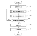
次に、画像形成システム100の動作について、図3を参照しながら具体的に説明する。図3の処理は、例えばユーザが画像形成の指示を行ったタイミングで開始される。但し、図3の処理の開始タイミングは、上記のタイミングに限らない。
先ずS1において、画像処理装置10の画像情報取得部101は、画像情報を取得し、これをRAM13等に記録する。以下、入力部104に入力される画像情報について説明する。画像情報は、例えば2次元の離散的な画像信号であり、画素ごとに異方性を示すBRDF(SVBRDF:Spatially-Varying BRDF)をモデル化した関数のパラメータを有する。本実施形態では、BRDFのモデルとして、次式で示す異方性のパラメトリックモデル(Wardモデル)を用いた例について説明する。なお、BRDFのモデルはこれに限定されるものではなく、異方性を表現可能なモデルであれば、どのようなモデルであってもよい。
Next, the operation of the
First, in S1, the image

ここで、Lは光源の方向を示す光源ベクトル、Vは視線の方向を示す視線ベクトルである。また、θlは画素の法線ベクトルと光源ベクトルLとのなす角、θvは画素の法線と視線ベクトルVとのなす角、θhは画素の法線ベクトルと、光源ベクトルLと視線ベクトルVとのハーフベクトルとのなす角である。また、φhはハーフベクトルと画素の接ベクトル(x軸)とのなす角である。さらに、ρdは拡散反射の強さを意味する拡散成分、ρsは鏡面反射の強さを意味するスペキュラー強度成分である。また、αxは鏡面反射の接ベクトル方向の広がりを示すスペキュラー拡がり成分、αyは鏡面反射の縦法線ベクトル方向の広がりを示すスペキュラー拡がり成分である。スペキュラー拡がり成分を接ベクトル方向(x軸)と縦法線ベクトル方向(y軸)との2次元で表すことにより、光学的な異方性を表現することができる。 Here, L is a light source vector indicating the direction of the light source, and V is a line-of-sight vector indicating the direction of the line of sight. Θ l is the angle between the pixel normal vector and the light source vector L, θ v is the angle between the pixel normal and the line-of-sight vector V, θ h is the pixel normal vector, the light source vector L and the line-of-sight The angle between the vector V and the half vector. Φ h is an angle formed by the half vector and the pixel tangent vector (x-axis). Furthermore, ρ d is a diffuse component that means the intensity of diffuse reflection, and ρ s is a specular intensity component that means the intensity of specular reflection. Further, α x is a specular spread component indicating the spread in the tangent vector direction of specular reflection, and α y is a specular spread component indicating the spread in the vertical normal vector direction of specular reflection. The optical anisotropy can be expressed by expressing the specular spread component in two dimensions of the tangent vector direction (x-axis) and the vertical normal vector direction (y-axis).
各画素は、上記の4つのパラメータ(ρd,ρs,αx,αy)を、R(レッド)、G(グリーン)、B(ブルー)の3つの色情報に対してそれぞれ有する。また、接ベクトル(x軸)は画素ごとに方向が異なるよう定義可能であり、各画素の接ベクトルと2次元画像平面の横軸との回転角φを画素ごとに有する。すなわち、各画素において、4パラメータ(ρd,ρs,αx,αy)×3色(R、G、B)+1(回転角φ)の計13の情報を有する。そこで、上記画像情報は、これらの情報を浮動小数点の上記13次元を同時化した2次元画像情報として入力する。ただし、これらの情報の入力の仕方はこれに限るものではない。 Each pixel has the above four parameters (ρ d , ρ s , α x , α y ) for three color information of R (red), G (green), and B (blue). The tangent vector (x-axis) can be defined so that the direction is different for each pixel, and has a rotation angle φ between the tangent vector of each pixel and the horizontal axis of the two-dimensional image plane for each pixel. That is, each pixel has a total of 13 pieces of information of 4 parameters (ρ d , ρ s , α x , α y ) × 3 colors (R, G, B) +1 (rotation angle φ). Therefore, the image information is input as two-dimensional image information obtained by synchronizing the 13-dimensional floating point. However, the method of inputting such information is not limited to this.
次にS2では、画像処理装置10の色材制御量決定部102は、S1において取得した画像情報に基づいて、所定の画素に対応する色材制御量を決定する色材制御量決定処理を実行する。色材制御量決定処理については、後で詳述する。また、S3では、画像処理装置10の形状制御量決定部103は、S1において取得した画像情報とS2において決定した色材制御量とに基づいて、所定の画素に対応する形状制御量を決定する形状制御量決定処理を実行する。形状制御量決定処理については、後で詳述する。次にS4において、全画素について処理したか(色材制御量と形状制御量とを決定したか)を判定する。そして、処理していない画素が存在する場合には未処理の画素を選択してS2に戻り、全画素について処理が完了している場合にはS5に移行する。
Next, in S2, the color material control
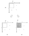
図4(a)に示すように、S1において取得される画像情報の各画素31は、(i,j)の2次元方向にタイル状に並んでいる。各画素31は、画素情報として、それぞれ上記の13次元の情報を有する。色材制御量決定部102は、図4(b)に示すように、各画素31に対応する位置32に表面色を形成するための色材制御量として、例えば、R(レッド)、G(グリーン)、B(ブルー)の各8ビットが同時化された情報を決定する。表面色形成装置201は、このR,G、Bの色材制御量に対してシアン、マゼンタ、イエロー、ブラック等の色材量を決定し、所定の基材表面に所定のインクを塗布、定着させることで表面色を形成する。なお、本実施形態では、色材制御量としてR、G、B、を決定する場合について説明するが、これに限るものではなく、例えばCMYKや特色に対応した色情報を色材制御量としてもよい。
As shown in FIG. 4A, the
また、形状制御量決定部103は、図4(c)に示すように、各画素31に対応する形状制御量として、6×6の高さ情報を決定する。すなわち、画像情報の縦、横の画素数をそれぞれNi、Njとすると、形状制御量決定部103が決定する形状制御量の格子点数は、縦6×Ni、横6×Njとなる。ここで、形状制御量決定部103は、形状制御量(高さ情報)として、例えば、格子点33ごとに8ビットの情報を決定する。形状形成装置202は、その形状制御量に基づいて、樹脂等の所定の基材表面に凹凸形状を作成する。なお、本実施形態では、1画素に対して6×6の高さ情報を制御する場合について説明するが、これに限定されるものではなく、その格子点数やビット数を限定するものではない。
このように、各画素の形状と色材とを決定し、これらを制御することでSVBRDFを再現する。本実施形態では、SVBRDFの1画素を、6×6の格子点の高さ情報(形状情報)と、1画素で均一な(全ポリゴンが同じ)色材値とで再現する。
Further, the shape control
In this way, the SVBRDF is reproduced by determining the shape and color material of each pixel and controlling them. In the present embodiment, one pixel of SVBRDF is reproduced with height information (shape information) of 6 × 6 grid points and color material values that are uniform for all pixels (the same for all polygons).
図3のS5では、形状形成装置202は、S3において形状制御量決定部103が決定した形状制御量に基づく3次元形状を基材表面に有する画像を樹脂等で形成する。最後にS6では、表面色形成装置201は、S5において形状形成装置202によって形状された画像に対し、S2において色材制御量決定部102が決定した色材制御量に基づいて色付けする。
図3のS2では、図5に示す色材制御量決定処理を実行する。図5の処理は、画像処理装置10のCPU11が、ROM12等に記憶された必要なプログラムを読み出して実行することにより実現される。この色材制御量決定処理では、拡散成分を示すパラメータρdと、スペキュラー強度成分を示すρsとに基づいて、各画素の色材制御量としてRGB値(色材値)を決定する。本実施形態では、パラメータρd及びρsをもとに、色材ルックアップテーブル(色材LUT)を参照し、色材制御量を決定する。色材LUTの一例を図6に示す。
In S5 of FIG. 3, the
In S2 of FIG. 3, the color material control amount determination process shown in FIG. 5 is executed. The processing of FIG. 5 is realized by the
図6に示すように、色材LUTには、BRDFモデルの4つのパラメータρd,ρs,αx,αyが、RGB値と対応付けられて記憶されている。図6の色材LUTにおいて、列41はRGB値、列42〜列45は上記4つのパラメータの色ごとの値である。なお、この色材LUTは、列41の色を有するパッチ画像データを作成し、これを表面色形成装置201に入力して形成した画像をゴニオフォトメータ等の所定の測定方法で測定することで作成可能である。
色材制御量決定部102は、図6に示すような色材LUTの全ての行に対し、画像情報取得部102が取得したパラメータρd及びρsと、色材LUTの列42のρd及びρsとを比較する。そして、色材制御量決定部102は、最も類似度の高い行における列41のRGB値を、色材制御量として決定する。
As shown in FIG. 6, in the color material LUT, four parameters ρ d , ρ s , α x , and α y of the BRDF model are stored in association with RGB values. In the color material LUT of FIG. 6,
Colorant control
すなわち、色材制御量決定部102は、図5のS21において、先ず外部メモリ14等に記憶された色材LUTを読出し、S22に移行する。S22では、色材制御量決定部102は、色材LUTにおいて選択した所定の行について、上記類似度を算出する。本実施形態では、距離に基づく評価値Dを類似度として算出する。評価値Dは、次式をもとに算出する。
D=ΔEd+k・ΔEs ………(3)
ここで、kは定数である。また、ΔEd及びΔEsは、次式により求められる。
That is, the color material control
D = ΔEd + k · ΔEs (3)
Here, k is a constant. Further, ΔEd and ΔEs are obtained by the following equations.
ここで、ρd_r,ρd_g,ρd_bは、画像情報取得部101から入力した拡散成分ρdの各色情報(R、G、B)、ρs_r,ρs_g,ρs_bは、画像情報取得部101から入力したスペキュラー強度成分ρsの各色情報(R、G、B)である。さらに、ρdLUT_r[m],ρdLUT_g[m],ρdLUT_b[m]は、色材LUTのm行目における列42のr,g,bの値、ρsLUT_r[m],ρsLUT_g[m],ρsLUT_b[m]は、色材LUTのm行目における列43のr,g,bの値である。
Here, ρ d _r, ρ d _g , ρ d _b , each color information of the diffuse component [rho d input from the image information acquiring unit 101 (R, G, B) , ρ s _r, ρ s _g, ρ s _b Is the color information (R, G, B) of the specular intensity component ρ s input from the image
次にS23では、色材制御量決定部102は、S22において算出した評価値Dが、これまでに算出した評価値Dの中で最小であるか否かを判定する。そして、最小である場合にはS24に移行して選択中の色材LUTの行における列41のRGB値、列44のパラメータαx、及び列45のパラメータαyを記憶し、S25に移行する。一方、S23において評価値Dが最小ではないと判定した場合には、そのままS25に移行する。S25では、色材制御量決定部102は、評価値Dの算出及び判定処理を色材LUTの全点(全行)について行ったか否かを判定する。そして、評価値Dの算出及び判定処理を行っていない行がある場合にはS22に戻り、色材LUTの全行について処理を行った場合には図3のS3に移行する。
Next, in S23, the color material control
このように、色材LUTを用い、評価値Dが最小となるRGB値を当該画素における色材制御量として決定する。また、このとき、決定した色材制御量に対応するスペキュラー拡がり成分αx及びαyも同時に記憶し、これらの値は、スペキュラー拡がり成分αx´及びαy´として形状制御量決定部103が参照できるようにする。ここで、スペキュラー拡がり成分αx´及びαy´は、決定した色材制御量に基づいて表面色形成装置201において表面色を形成したときのスペキュラー拡がり成分に相当する。なお、色材制御量の決定方法は、上記の方法に限定されるものではなく、既知の様々なカラーマッチングアルゴリズムを応用することが可能である。
Thus, using the color material LUT, the RGB value that minimizes the evaluation value D is determined as the color material control amount for the pixel. At this time, the specular spread components α x and α y corresponding to the determined color material control amount are also stored at the same time, and the shape control
図3のS3では、図7に示す形状制御量決定処理を実行する。図7の処理は、画像処理装置10のCPU11が、ROM12等に記憶された必要なプログラムを読み出して実行することにより実現される。この形状制御量決定処理では、スペキュラー拡がり成分αx及びαyと、回転角φと、スペキュラー拡がり成分αx´及びαy´とに基づいて、各画素の形状制御量として6×6の高さ情報を決定する。
先ず図7のS31において、形状制御量決定部103は、輝度に対するスペキュラー拡がり成分を算出する。具体的には、パラメータαx,αy,αx´,αy´において、例えばR,G,Bの3色のカラー情報の加重平均をとるなどの方法を用いる。なお、形状制御量決定処理における以降の説明では、この加重平均された値をそれぞれパラメータαx,αy,αx´,αy´と表記する。
In S3 of FIG. 3, the shape control amount determination process shown in FIG. 7 is executed. The processing in FIG. 7 is realized by the
First, in S31 of FIG. 7, the shape control
次にS32では、形状制御量決定部103は、x方向とy方向のそれぞれについて、スペキュラー拡がり成分の比率XratioとYratioを算出する。
Xratio=αx/αx´ ………(6)
Yratio=αy/αy´ ………(7)
本実施形態では、比率Xratio及びYratioをもとに、形状ルックアップテーブル(形状LUT)を参照し、形状制御量を決定する。
すなわち、S33では、形状制御量決定部103は、外部メモリ14等に記憶された形状LUTを読出し、S34に移行する。S34では、形状制御量決定部103は、比率Xratio及びYratioをもとに、形状LUTを参照し、形状制御量のベース形状を決定する。形状LUTの一例を図8に示す。
Next, in S <b> 32, the shape control
Xratio = α x / α x ′ (6)
Yratio = α y / α y ′ (7)
In the present embodiment, the shape control amount is determined with reference to the shape lookup table (shape LUT) based on the ratios Xratio and Yratio.
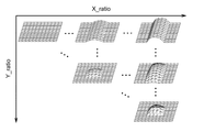
That is, in S33, the shape control
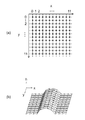
図8に示すように、形状LUTには、ベース形状情報が比率Xratio及びYratioと対応付けられて記憶されている。図8の形状LUTにおいて、列51は比率Xratio及びYratio、列52はベース形状情報である。本実施形態では、1画素に対し、形状制御量として6×6の高さ情報を算出する。そのため、形状LUTには、6×6の以上の大きさの格子点について高さ情報h(p,q)を記録したベース形状情報を複数設定しておく。図9(a)は、ベース形状情報の格子点の一例を示す図、図9(b)は、ベース形状情報の3次元形状の一例を示す図である。このように、例えば、x方向、y方向に各12点、計12×12=114点の格子点を設定し、各格子点について高さ情報を設定しておく。
このように、出力する高さ情報である6×6よりも大きいサイズの格子点で高さ情報を設定することで、後述する回転処理(図7のS36)を施しても6×6の出力サイズ範囲で高さ情報を算出することができる。なお、この格子点のサイズは、出力するサイズの1辺の格子点の√2倍以上のサイズであることが好ましい。
As shown in FIG. 8, base shape information is stored in the shape LUT in association with the ratios Xratio and Yratio. In the shape LUT of FIG. 8,
In this way, by setting the height information with a grid point having a size larger than 6 × 6 which is the height information to be output, 6 × 6 output is performed even if rotation processing (S36 in FIG. 7) described later is performed. Height information can be calculated in the size range. The size of the lattice point is preferably at least √2 times the size of the lattice point on one side of the output size.
また、後述する回転処理があるため、形状LUTは、図10に示すように上三角行列に対応するベース形状情報を保持すればよい。ここで、図10に示すように、比率Xratio又はYratioが大きくなるほど形状の凹凸が大きくなるように設定することで、比率Xratio又はYratioが大きくなるほどスペキュラーの拡がりを大きく再現することができる。さらに、比率XratioとYratioとが等しい対角線上は、スペキュラーの拡がりを等方的にするために、x方向とy方向で同じ形状となるように設定することが好ましい。また、比率XratioとYratioとの差が大きいほど、異方性を強く再現するために、x方向とy方向とで形状が異なるよう設定することが好ましい。 Further, since there is a rotation process to be described later, the shape LUT may hold base shape information corresponding to the upper triangular matrix as shown in FIG. Here, as shown in FIG. 10, by setting the shape unevenness as the ratio Xratio or Yratio increases, it is possible to reproduce specular expansion as the ratio Xratio or Yratio increases. Further, on the diagonal line where the ratios Xratio and Yratio are equal, it is preferable to set the same shape in the x direction and the y direction in order to make the specular expansion isotropic. In order to reproduce the anisotropy more strongly as the difference between the ratio Xratio and Yratio increases, it is preferable to set the shape different in the x direction and the y direction.
このように図7のS34でベース形状を決定したら、次にS35において、形状制御量決定部103は、表面形状の法線の変化率を制限するための形状補正処理を実施する。形状情報の法線の変化に対し、色材のスペキュラー拡がり成分αx´やαy´が小さい場合、凹凸の法線方向に応じて複数の方向に正反射光が分離してしまう。そこで、このS35では、色材のスペキュラー拡がり成分αx´及びαy´に応じて凹凸の法線の変化率を制限するようベース形状を補正する。
If the base shape is determined in S34 of FIG. 7 in this way, in S35, the shape control
具体的には、x方向に高さ情報の変化(微分値)を算出し、その値が、スペキュラー拡がり成分αx´に応じて予め設定された閾値より大きい場合、高さ情報に1未満の値を乗算することで高さを低くする処理を繰返し行う。次に、y方向についても同様に、y方向に高さ情報の変化率(微分値)を算出し、その値がスペキュラー拡がり成分αy´に応じて予め設定された閾値より大きい場合、高さ情報に1未満の値を乗算することで高さを低くする処理を繰返し行う。 Specifically, a change (differential value) of height information in the x direction is calculated, and when the value is larger than a threshold set in advance according to the specular spread component α x ′, the height information is less than 1. The process of decreasing the height by multiplying the values is repeated. Next, similarly for the y direction, the rate of change (differential value) of the height information is calculated in the y direction, and if the value is larger than the threshold set in advance according to the specular spread component α y ′, the height The process of decreasing the height by multiplying the information by a value less than 1 is repeated.
最後に、S36では、形状制御量決定部103は、S35において補正されたベース形状を回転角φだけ回転させ、最終的に出力する6×6サイズの高さ情報を算出する。このS36では、形状制御量決定部103は、先ずS35において補正されたベース形状である12×12の高さ情報を、その中心座標(図9(a)では(x,y)=(5.5,5.5))を中心にx、yを回転角φだけ回転させたx´、y´座標を求める。つぎに、出力する6×6の高さ情報に相当するx、y座標の高さhをx´、y´、hの空間から補間処理等にて算出する。図7(a)においては、中心座標を中心とする6×6の格子点(x座標3〜8、y座標3〜8)に対する高さをx´、y´、h空間から算出し、その高さ情報を当該画素の形状情報とする。
Finally, in S36, the shape control
以上のように、画像処理装置10は、形成対象の画像に関する画像情報として、画素ごとにBRDFに関する情報を取得する。そして、画像処理装置10は、取得した画像情報に基づいて、表面色形成装置201において形成対象の画像の各画素の色を形成するための色材制御量(色材制御情報)を決定する。また、画像処理装置10は、決定した色材制御量と、取得した画像情報におけるスペキュラー拡がり成分とに基づいて、形状形成装置202において形成対象の画像の各画素の形状を形成するための形状制御量(形状情報)を決定する。このように、本実施形態では、目的となるスペキュラー拡がり成分と、画素ごとの色材制御量とに基づいて、表面形状を形成するための形状制御量を一意に決定することができる。
As described above, the
また、画像処理装置10は、1画素ごとに色材制御量を決定する。すなわち、1画素中の全ポリゴンにおいて色材値は同値とする。このように、ポリゴンごとではなく、1画素で均一な色材制御量を決定するので、色材制御量及び形状制御量の決定に必要な計算量を大幅に削減することができる。
また、形状制御量の決定に際し、画像処理装置10は、入力した画像情報におけるスペキュラー拡がり成分(αx,αy)と、色材制御量に基づいて表面色形成装置201において色を形成したときのスペキュラー拡がり成分(αx´,αy´)とを用いる。具体的には、画像処理装置10は、入力した画像情報におけるスペキュラー拡がり成分と、色材制御量に基づいて表面色形成装置201において色を形成したときのスペキュラー拡がり成分との比率に基づいて、形状制御量を決定する。したがって、表面色形成装置201によって表面に色材の層が作られることによるスペキュラー拡がりを考慮して、目的となるスペキュラーの拡がりを再現可能な形状制御量を決定することができる。
Further, the
In determining the shape control amount, the
さらに、画像処理装置10は、上記スペキュラー拡がり成分の比率と形状制御量との対応を示すルックアップテーブル(形状LUT)を参照し、当該比率に基づいて形状制御量を決定する。このように、形状LUTを用いることで、簡易に入力情報の光学的異方性を再現するための形状制御量を決定することが可能となる。
このとき、画像処理装置10は、色材制御量に基づいて表面色形成装置201において色を形成したときのスペキュラー拡がり成分に対する、入力した画像情報におけるスペキュラー拡がり成分の比率(αx/αx´,αy/αy´)を導出する。そして、画像処理装置10は、当該比率が大きいほど、スペキュラー拡がりが大きくなるように形状制御量を決定する。したがって、適切に入力情報の光学的異方性を再現するための形状制御量を決定することが可能となる。
Further, the
At this time, the
また、画像処理装置10は、色材制御量と、当該色材制御量に基づいて表面色形成装置201において色を形成したときのスペキュラー拡がり成分(αx´,αy´)との対応を示すルックアップテーブル(色材LUT)を予め保持する。そして、画像処理装置10は、色材LUTを参照し、色材制御量に基づいてスペキュラー拡がり成分(αx´,αy´)を導出する。したがって、簡易にスペキュラー拡がり成分(αx´,αy´)を導出することができる。
ここで、スペキュラー拡がり成分を示す情報は、接ベクトル方向(x軸)と縦法線ベクトル方向(y軸)との2次元で表す。したがって、スペキュラー拡がりの異方性を適切に表現することができる。また、入力する画像情報は、複数の色(RGB)ごとのBRDFに関する情報とするので、適切に形成対象の画像を形成することができる。
Further, the
Here, the information indicating the specular spread component is expressed in two dimensions, the tangent vector direction (x axis) and the vertical normal vector direction (y axis). Therefore, the specular expansion anisotropy can be appropriately expressed. Further, since the input image information is information related to BRDF for each of a plurality of colors (RGB), an image to be formed can be appropriately formed.
また、画像処理装置10は、色材制御量に基づいて、形状形成装置202において形成される形状の法線の変化率を制限するための形状補正処理を形状制御量に対して施す。具体的には、画像処理装置10は、色材制御量に基づいて表面色形成装置201において色を形成したときのスペキュラー拡がり成分(αx´,αy´)に応じて決定される閾値を用い、閾値処理により形状制御量を補正する。これにより、形状の法線の変化に対し、色材のスペキュラー拡がり成分(αx´,αy´)が小さくなることに起因する正反射光の分離を抑制することができる。
さらに、画像処理装置10は、入力した画像情報におけるBRDFの拡散成分(ρd)とスペキュラー強度成分(ρs)とに基づいて、色材制御量を決定する。したがって、目的とする拡散反射の強さや鏡面反射の強さを適切に再現することができる。また、画像処理装置10は、色材制御量の決定に際し、拡散成分(ρd)とスペキュラー強度成分(ρs)と色材制御量との対応を示すルックアップテーブル(色材LUT)を用いる。したがって、簡易に色材制御量を決定することができる。
以上のように、本実施形態では、複雑な演算を行うことなく、適切に光学的異方性を有する画像を形成することができる。
Further, the
Further, the
As described above, in the present embodiment, an image having appropriate optical anisotropy can be formed without performing complicated calculations.
(変形例1)
上記実施形態においては、図9(a)に示したように、ベース形状の格子点を正方格子として説明したが、これに限定されるものではない。例えば、図11(a)に示すように、中心座標を中心に同心円状に格子点を配置させることも可能である。同心円状の格子点を用いてベース形状を決定することで、図11(b)に示すように、半球状の形状をより精度良く形成することが可能となる。この場合、BRDFを再現する領域の単位である1画素の形を図11(a)の符号61に示すように正六角形としてもよい。この場合、正六角形の形状をもつ画素61を、図11(c)に示すようにハニカム構造を有するよう並べることができる。これにより、正六角形のハニカム構造を構成する領域ごとにスペキュラー拡がり成分が変化するように設定することができる。したがって、BRDFを再現する画素の密度が方向によって変化しないようにすることができる。
BRDFを再現する画素の密度が方向によって変わってしまうと、観察距離を離して観察した場合など、複数の画素をまとめてみたときのマクロなBRDFに意図しない光沢異方性が出てしまうおそれがある。上記のように、方向によって密度が一定となるよう画素を配置することにより、そのような弊害が生じない高画質な画像を獲得できる。
(Modification 1)
In the above embodiment, as shown in FIG. 9A, the base-shaped lattice points are described as square lattices, but the present invention is not limited to this. For example, as shown in FIG. 11A, lattice points can be arranged concentrically around the center coordinates. By determining the base shape using concentric lattice points, a hemispherical shape can be formed with higher accuracy as shown in FIG. In this case, the shape of one pixel, which is a unit of a region for reproducing BRDF, may be a regular hexagon as indicated by
If the density of the pixels that reproduce BRDF changes depending on the direction, there is a risk that unintended gloss anisotropy may appear in macro BRDF when a plurality of pixels are grouped together, such as when observed at a distance from the observation distance. is there. As described above, by arranging the pixels so that the density is constant depending on the direction, a high-quality image that does not cause such a problem can be obtained.
(変形例2)
上記実施形態においては、表面色形成装置201によって表面に色材の層が作られることによる形状情報の変化を考慮して、形状制御量を決定するようにしてもよい。図12(a)は、平滑な面に表面色形成装置201にて色材を塗布した後の形状を示している。図12(b)に示す形状情報を形状形成装置202によって形成した後、表面色形成装置201によって色の層を形成すると、図12(a)と図12(b)との形状が合わさった図12(c)のような形状となる。
そこで、先ず色材制御量に基づいて、ルックアップテーブルや表面色形成装置201のハーフトーン処理情報等を用いて図12(a)に該当する色の層の形状情報を算出する。次に、意図する図12(c)の形状情報から、上記の算出した色の層の形状情報を差し引く。これにより、図12(b)に該当する形状制御量を決定することができる。このようにすることで、最終的に意図する形状を有する画像を適切に形成することが可能となる。
(Modification 2)
In the above embodiment, the shape control amount may be determined in consideration of a change in shape information due to the color material layer being formed on the surface by the surface
Therefore, based on the color material control amount, shape information of the color layer corresponding to FIG. 12A is calculated using a look-up table, halftone processing information of the surface
(第二の実施形態)
次に、本発明の第二の実施形態について説明する。
上記第一の実施形態においては、形状LUTを用いて形状制御量を決定する場合について説明した。これに対して、第二の実施形態では、形状LUTを用いずに形状制御量を決定する。図13は、形状LUTを用いずに形状制御量を決定する形状制御量決定処理を示すフローチャートである。この図13の処理は、図7におけるS33及びS34が、S311及びS312に置換されていることを除いては、図7の処理と同様である。したがって、以下、処理の異なる部分を中心に説明する。
S311では、形状制御量決定部103は、x方向の中心角θxと、y方向の中心角θyとをそれぞれ算出する。本実施形態では、スペキュラーの拡がりを、形状情報の微平面の法線の分布を制御することで再現する。具体的には、当該法線が分布する範囲が許容分布範囲内となるように形状制御量を決定する。中心角θx及びθyは、許容分布範囲を決定するための円弧の中心角である。
(Second embodiment)
Next, a second embodiment of the present invention will be described.
In the first embodiment, the case where the shape control amount is determined using the shape LUT has been described. On the other hand, in the second embodiment, the shape control amount is determined without using the shape LUT. FIG. 13 is a flowchart showing shape control amount determination processing for determining a shape control amount without using the shape LUT. The process in FIG. 13 is the same as the process in FIG. 7 except that S33 and S34 in FIG. 7 are replaced with S311 and S312. Therefore, the following description will focus on the different parts of the process.
In S311, the shape control
図14は、x方向の中心角θxを説明する図である。x軸上の各格子点における高さ情報hは、円71における円弧72上に形成される。この円弧72は、中心角θxと格子点の範囲(図11ではx=0〜11の範囲)が決定すれば描くことができる。すなわち、中心角θxにより円弧72を変化させることができる。換言すると、中心角θx及びθyによって形状情報の法線の分布範囲を制御することができる。
図13のS311では、形状制御量決定部103は、S32において算出した比率Xratioから中心角θxを、比率Yratioから中心角θyをそれぞれ算出する。中心角θx及びθyの算出には、例えば予め設定した関数や1次元ルックアップテーブル等を用いる。
次にS312では、形状制御量決定部103は、中心角θx及びθyに応じた各格子点の高さ情報h(x,y)を算出する。高さ情報h(x,y)は、次式により算出することができる。
FIG. 14 is a diagram for explaining the central angle θx in the x direction. Height information h at each lattice point on the x-axis is formed on an
In S311 of FIG. 13, the shape control
In step S312, the shape control
上記において、h(x,y)<0のときは、h(x,y)=0とする。
ここで、(cx,cy)は格子点の中心座標であり、図13に示す例では(cx,cy)=(5.5,5.5)となる。また、dx,dyは、円弧範囲を決定する定数であり、中心からの距離で与えられる。例えば、1画素の高さ情報を最終的に6×6のサイズで表す場合、dx,dyはそれぞれ6の半分の3に設定することができる。ただし、dx,dyの設定方法はこれに限るものではない。図14は、上記の方法により形成される高さ情報の例である。この図14では、dxを約2.5、dyを約5、θxを約179°、θyを約120°に設定したときの高さ情報を示している。
このように、形状ルックアップテーブルを用いない方法によれば、必要なメモリ容量が削減されるため、より低コストで光学的異方性のあるコンテンツを出力することが可能となる。
In the above, when h (x, y) <0, h (x, y) = 0.
Here, (c x , c y ) is the center coordinates of the lattice points, and in the example shown in FIG. 13, (c x , c y ) = (5.5, 5.5). D x and dy are constants that determine the arc range, and are given by the distance from the center. For example, when representing one pixel height information the size of the final 6 × 6, can be set to d x, d y half 3 of each 6. However, d x, how to set the d y is not limited to this. FIG. 14 is an example of height information formed by the above method. FIG. 14 shows height information when d x is about 2.5, dy is about 5, θ x is about 179 °, and θ y is about 120 °.
As described above, according to the method that does not use the shape look-up table, the necessary memory capacity is reduced. Therefore, it is possible to output contents having optical anisotropy at a lower cost.
(その他の変形例)
上記実施形態では、図7や図13のS36において、回転角φに基づいてベース形状情報を回転させる回転処理を実施したが、これに限るものではない。すなわち、回転を無視できる場合、当該回転処理は省略可能である。
また、上記実施形態においては、画素ごとの法線ベクトルを入力するパラメータとして追加し、算出した形状情報に対して、法線ベクトルの向きが入力されたものと一致するよう形状を変形させる変形処理を実施するようにしてもよい。これにより、法線ベクトルが画素ごとに異なる画像であっても精度良く再現することが可能となる。
さらに、上記実施形態においては、スペキュラー拡がり成分として2次元のαx,αyを入力する場合について説明したが、異方性の再現が必要でない場合は、1次元のスペキュラー拡がり成分を入力するようにしてもよい。この場合、形状ルックアップテーブルは、αx=αyとなる場所(図10の対角要素)を参照するようにすればよい。
また、各画素の色情報、例えばRGB値などを、双方向反射率分布関数とは別に取得してもよい。
(Other variations)
In the above embodiment, the rotation process for rotating the base shape information based on the rotation angle φ is performed in S36 of FIG. 7 or FIG. 13, but the present invention is not limited to this. That is, when the rotation can be ignored, the rotation process can be omitted.
Further, in the above embodiment, a deformation process is performed in which the normal vector for each pixel is added as a parameter for input, and the shape is deformed so that the calculated shape information matches the input direction of the normal vector. May be implemented. Thereby, even if the normal vector is different for each pixel, it can be accurately reproduced.
Furthermore, in the above-described embodiment, the case where two-dimensional α x and α y are input as specular expansion components has been described. However, when it is not necessary to reproduce anisotropy, a one-dimensional specular expansion component is input. It may be. In this case, the shape look-up table may refer to a place (diagonal element in FIG. 10) where α x = α y .
Further, the color information of each pixel, for example, the RGB value may be acquired separately from the bidirectional reflectance distribution function.
(その他の実施形態)
本発明は、上述の実施形態の1以上の機能を実現するプログラムを、ネットワーク又は記憶媒体を介してシステム又は装置に供給し、そのシステム又は装置のコンピュータにおける1つ以上のプロセッサーがプログラムを読出し実行する処理でも実現可能である。また、1以上の機能を実現する回路(例えば、ASIC)によっても実現可能である。
(Other embodiments)
The present invention supplies a program that realizes one or more functions of the above-described embodiments to a system or apparatus via a network or a storage medium, and one or more processors in a computer of the system or apparatus read and execute the program This process can be realized. It can also be realized by a circuit (for example, ASIC) that realizes one or more functions.
10…画像処理装置、20…画像形成装置、100…画像形成システム、101…画像情報取得部、102…色材制御量決定部、103…形状制御量決定部、201…表面色形成装置、202…形状形成装置
DESCRIPTION OF
Claims (16)
前記画像の画素ごとの光学的な異方性に関する異方性情報を取得する取得手段と、
前記異方性情報に基づいて、前記画像の画素ごとの前記色材制御情報を決定する第一の決定手段と、
前記異方性情報に基づいて、前記画像の画素ごとの前記形状情報を決定する第二の決定手段と、を備え、
前記形状情報は、画素に対応する複数の格子点の高さを表すことを特徴とする画像処理装置。 Color material control information for controlling the color material used when forming an image on the base material in order to reproduce optical anisotropy on the base material, and shape information representing the surface shape of the image And an image processing apparatus for determining
Obtaining means for obtaining anisotropy information relating to optical anisotropy for each pixel of the image;
First determining means for determining the color material control information for each pixel of the image based on the anisotropic information;
Second determining means for determining the shape information for each pixel of the image based on the anisotropic information,
The image processing apparatus, wherein the shape information represents heights of a plurality of lattice points corresponding to pixels.
前記第二の決定手段は、
前記色材制御情報に基づいて色材を記録した場合のスペキュラー拡がり成分を示す第二の情報を導出し、
前記第一の情報と前記第二の情報とに基づいて、前記形状情報を決定することを特徴とする請求項1に記載の画像処理装置。 The anisotropic information includes first information indicating a specular spreading component,
The second determining means includes
Deriving second information indicating a specular spread component when a color material is recorded based on the color material control information,
The image processing apparatus according to claim 1, wherein the shape information is determined based on the first information and the second information.
前記第二の決定手段は、
前記比率に基づいて前記第一の保持手段が保持するルックアップテーブルを参照し、前記形状情報を決定することを特徴とする請求項2に記載の画像処理装置。 A first holding means for holding a look-up table indicating a correspondence between the ratio between the first information and the second information and the shape information;
The second determining means includes
The image processing apparatus according to claim 2, wherein the shape information is determined by referring to a look-up table held by the first holding unit based on the ratio.
前記第一の情報と前記第二の情報との比率に基づいて前記表面形状の法線の許容分布範囲を設定し、前記表面形状の法線が分布する範囲が前記許容分布範囲内となるように前記形状情報を決定することを特徴とする請求項2に記載の画像処理装置。 The second determining means includes
An allowable distribution range of the surface shape normal is set based on a ratio between the first information and the second information, and a range in which the normal of the surface shape is distributed is within the allowable distribution range. The image processing apparatus according to claim 2, wherein the shape information is determined.
前記第二の決定手段は、
前記色材制御情報に基づいて前記第二の保持手段が保持するルックアップテーブルを参照し、前記第二の情報を導出することを特徴とする請求項2乃至5のいずれか1項に記載の画像処理装置。 A second holding means for holding a lookup table indicating correspondence between the color material control information and the specular spread component when the color material is recorded based on the color material control information;
The second determining means includes
6. The second information is derived by referring to a look-up table held by the second holding unit based on the color material control information. Image processing device.
前記画像の各画素の双方向反射率分布関数における拡散成分とスペキュラー強度成分とに基づいて、前記色材制御情報を決定することを特徴とする請求項8に記載の画像処理装置。 The first determining means includes
The image processing apparatus according to claim 8, wherein the color material control information is determined based on a diffusion component and a specular intensity component in a bidirectional reflectance distribution function of each pixel of the image.
前記第一の決定手段は、
前記拡散成分と前記スペキュラー強度成分とに基づいて、前記第三の保持手段が保持するルックアップテーブルを参照し、前記色材制御情報を決定することを特徴とする請求項9に記載の画像処理装置。 A third holding means for holding a lookup table indicating correspondence between the diffusion component, the specular intensity component, and the color material control information;
The first determining means includes
The image processing according to claim 9, wherein the color material control information is determined by referring to a look-up table held by the third holding unit based on the diffusion component and the specular intensity component. apparatus.
前記色材制御情報に基づいて、前記表面形状の法線の変化率を制限することを特徴とする請求項1乃至10のいずれか1項に記載の画像処理装置。 The second determining means includes
The image processing apparatus according to claim 1, wherein a rate of change of the normal of the surface shape is limited based on the color material control information.
ハニカム構造を構成する正六角形の領域ごとに前記形状情報を決定することを特徴とする請求項1乃至11のいずれか1項に記載の画像処理装置。 The second determining means includes
The image processing apparatus according to any one of claims 1 to 11, wherein the shape information is determined for each regular hexagonal region constituting the honeycomb structure.
前記画像の画素ごとの光学的な異方性に関する異方性情報を取得するステップと、
前記異方性情報に基づいて、前記画像の画素ごとの前記色材制御情報を決定するステップと、
前記異方性情報に基づいて、前記画像の画素ごとの前記形状情報を決定するステップと、を含み、
前記形状情報は、画素に対応する複数の格子点の高さを表すことを特徴とする画像処理方法。 Color material control information for controlling the color material used when forming an image on the base material in order to reproduce optical anisotropy on the base material, and shape information representing the surface shape of the image And an image processing method for determining
Obtaining anisotropy information regarding optical anisotropy for each pixel of the image;
Determining the color material control information for each pixel of the image based on the anisotropic information;
Determining the shape information for each pixel of the image based on the anisotropy information,
The image processing method, wherein the shape information represents heights of a plurality of lattice points corresponding to pixels.
Priority Applications (2)
| Application Number | Priority Date | Filing Date | Title |
|---|---|---|---|
| JP2015094485A JP6604744B2 (en) | 2015-05-03 | 2015-05-03 | Image processing apparatus, image processing method, image forming system, and program |
| US15/139,043 US10235342B2 (en) | 2015-05-03 | 2016-04-26 | Image processing apparatus, image processing method, and storage medium |
Applications Claiming Priority (1)
| Application Number | Priority Date | Filing Date | Title |
|---|---|---|---|
| JP2015094485A JP6604744B2 (en) | 2015-05-03 | 2015-05-03 | Image processing apparatus, image processing method, image forming system, and program |
Publications (3)
| Publication Number | Publication Date |
|---|---|
| JP2016210058A JP2016210058A (en) | 2016-12-15 |
| JP2016210058A5 JP2016210058A5 (en) | 2018-06-14 |
| JP6604744B2 true JP6604744B2 (en) | 2019-11-13 |
Family
ID=57204555
Family Applications (1)
| Application Number | Title | Priority Date | Filing Date |
|---|---|---|---|
| JP2015094485A Active JP6604744B2 (en) | 2015-05-03 | 2015-05-03 | Image processing apparatus, image processing method, image forming system, and program |
Country Status (2)
| Country | Link |
|---|---|
| US (1) | US10235342B2 (en) |
| JP (1) | JP6604744B2 (en) |
Families Citing this family (6)
| Publication number | Priority date | Publication date | Assignee | Title |
|---|---|---|---|---|
| CN106346005B (en) * | 2016-10-25 | 2018-04-17 | 西安交通大学 | Flexible bidirectional redundancy-free powder spreading device for powder supply in self-powder-storage type selective laser melting |
| AU2017204504A1 (en) * | 2017-06-30 | 2019-01-17 | Canon Kabushiki Kaisha | System and method of rendering a graphical object with modification in structure |
| DK3794556T3 (en) * | 2018-05-18 | 2023-04-24 | Dental Imaging Technologies Corp | DENTAL 3D SCANNER WITH ANGLE-BASED SHARE MATCHING |
| WO2019218362A1 (en) * | 2018-05-18 | 2019-11-21 | 深圳配天智能技术研究院有限公司 | Object detection method, object detection device, and device having storage function |
| US11602898B2 (en) * | 2020-05-29 | 2023-03-14 | Ut-Battelle, Llc | Systems and methods for generating a graded lattice structure and their application to additive manufacturing |
| CN112848312B (en) * | 2021-02-01 | 2022-10-11 | 深圳市创想三维科技股份有限公司 | Method and device for detecting three-dimensional model object, computer equipment and storage medium |
Family Cites Families (16)
| Publication number | Priority date | Publication date | Assignee | Title |
|---|---|---|---|---|
| US6765573B2 (en) * | 2000-10-26 | 2004-07-20 | Square Enix Co., Ltd. | Surface shading using stored texture map based on bidirectional reflectance distribution function |
| US7768523B2 (en) * | 2006-03-09 | 2010-08-03 | Microsoft Corporation | Shading using texture space lighting and non-linearly optimized MIP-maps |
| GB0615956D0 (en) * | 2006-08-11 | 2006-09-20 | Univ Heriot Watt | Optical imaging of physical objects |
| WO2010026983A1 (en) * | 2008-09-03 | 2010-03-11 | 日本電気株式会社 | Image processing device, image processing method, and image processing program |
| JP5272718B2 (en) * | 2008-12-24 | 2013-08-28 | セイコーエプソン株式会社 | Texture information data acquisition device, display control system including the same, texture information data acquisition method, and computer program |
| JP5615041B2 (en) * | 2010-05-24 | 2014-10-29 | キヤノン株式会社 | Image processing apparatus and image processing method |
| CN102985943A (en) * | 2010-06-30 | 2013-03-20 | 日本电气株式会社 | Color image processing method, color image processing device, and color image processing program |
| JP5014475B2 (en) * | 2010-07-28 | 2012-08-29 | キヤノン株式会社 | Image processing apparatus and image processing method |
| JP5591017B2 (en) * | 2010-08-09 | 2014-09-17 | キヤノン株式会社 | Image processing apparatus and image processing method |
| JP2012048132A (en) * | 2010-08-30 | 2012-03-08 | Canon Inc | Image processor, image processing method, and program |
| JP5576745B2 (en) * | 2010-09-02 | 2014-08-20 | キヤノン株式会社 | Image processing apparatus and method |
| WO2014171988A2 (en) * | 2013-01-29 | 2014-10-23 | Andrew Robert Korb | Methods for analyzing and compressing multiple images |
| JP6051890B2 (en) * | 2013-01-29 | 2016-12-27 | 株式会社リコー | Image processing apparatus, image processing method, image display method, and program |
| US8982125B1 (en) * | 2014-05-15 | 2015-03-17 | Chaos Software Ltd. | Shading CG representations of materials |
| EP3032241B1 (en) * | 2014-12-11 | 2023-03-01 | X-Rite Europe GmbH | Method and apparatus for digitizing the appearance of a real material |
| JP6486096B2 (en) * | 2014-12-18 | 2019-03-20 | キヤノン株式会社 | Print data generation apparatus, print data generation method and program |
-
2015
- 2015-05-03 JP JP2015094485A patent/JP6604744B2/en active Active
-
2016
- 2016-04-26 US US15/139,043 patent/US10235342B2/en active Active
Also Published As
| Publication number | Publication date |
|---|---|
| JP2016210058A (en) | 2016-12-15 |
| US20160318259A1 (en) | 2016-11-03 |
| US10235342B2 (en) | 2019-03-19 |
Similar Documents
| Publication | Publication Date | Title |
|---|---|---|
| JP6604744B2 (en) | Image processing apparatus, image processing method, image forming system, and program | |
| AU2016349895B2 (en) | Light field display metrology | |
| JP2010130405A (en) | Printing control device and printing control system having the printing control device | |
| JP2000134490A (en) | Method and device for color signal conversion, recording medium, device driver, and color conversion table | |
| JP5195306B2 (en) | Material information data acquisition device and display control system including the same | |
| JP5587677B2 (en) | Topographic relief image generation method and topographic relief image generation apparatus | |
| JP2018037761A (en) | Color conversion table generating device, color conversion table generating method, and color conversion table generating program | |
| JP2016210058A5 (en) | ||
| JP4133996B2 (en) | Texture creation method | |
| JP6734809B2 (en) | Slice printing method for multicolor 3D objects | |
| US10475230B2 (en) | Surface material pattern finish simulation device and surface material pattern finish simulation method | |
| WO2016098297A1 (en) | Print data generating apparatus and print data generating method | |
| JP6433283B2 (en) | Image processing apparatus, image processing method, and program | |
| JP7258291B2 (en) | Image generation device and image generation method | |
| JP5398803B2 (en) | Color distribution design support system | |
| US10915092B2 (en) | Information processing apparatus and information processing method for reproducing the material appearance of an object on a recording medium | |
| JP6394989B2 (en) | Color gamut cross section acquisition method, color gamut cross section acquisition program, and color gamut cross section acquisition device | |
| JP5168030B2 (en) | Leather shape data generation device, leather shape data generation method, and leather shape data generation program | |
| TWI752983B (en) | Method, production setpoint, processor device, and system for producing image | |
| US20200031150A1 (en) | Method of printing with gloss control | |
| JP2013019729A (en) | Image capturing apparatus, method for controlling image capturing apparatus, three-dimensional measuring apparatus, and program | |
| JP6394990B2 (en) | Color gamut cross section acquisition method, color gamut cross section acquisition program, and color gamut cross section acquisition device | |
| JP2003030275A (en) | Method and device for preparing hairline pattern | |
| JP4416015B2 (en) | Color gamut information creation device, color gamut information creation method, and color gamut information creation program | |
| JP2017182538A (en) | Information processing unit, image evaluation method, manufacturing method of decorative material, decorative material, program and recording medium |
Legal Events
| Date | Code | Title | Description |
|---|---|---|---|
| A521 | Request for written amendment filed |
Free format text: JAPANESE INTERMEDIATE CODE: A523 Effective date: 20180427 |
|
| A621 | Written request for application examination |
Free format text: JAPANESE INTERMEDIATE CODE: A621 Effective date: 20180427 |
|
| A131 | Notification of reasons for refusal |
Free format text: JAPANESE INTERMEDIATE CODE: A131 Effective date: 20190618 |
|
| A521 | Request for written amendment filed |
Free format text: JAPANESE INTERMEDIATE CODE: A523 Effective date: 20190808 |
|
| TRDD | Decision of grant or rejection written | ||
| A01 | Written decision to grant a patent or to grant a registration (utility model) |
Free format text: JAPANESE INTERMEDIATE CODE: A01 Effective date: 20190917 |
|
| A61 | First payment of annual fees (during grant procedure) |
Free format text: JAPANESE INTERMEDIATE CODE: A61 Effective date: 20191015 |
|
| R151 | Written notification of patent or utility model registration |
Ref document number: 6604744 Country of ref document: JP Free format text: JAPANESE INTERMEDIATE CODE: R151 |