JP6603530B2 - Plasma processing apparatus and method for controlling plasma processing apparatus - Google Patents
Plasma processing apparatus and method for controlling plasma processing apparatus Download PDFInfo
- Publication number
- JP6603530B2 JP6603530B2 JP2015190947A JP2015190947A JP6603530B2 JP 6603530 B2 JP6603530 B2 JP 6603530B2 JP 2015190947 A JP2015190947 A JP 2015190947A JP 2015190947 A JP2015190947 A JP 2015190947A JP 6603530 B2 JP6603530 B2 JP 6603530B2
- Authority
- JP
- Japan
- Prior art keywords
- water
- tank
- sensor
- tip
- height direction
- Prior art date
- Legal status (The legal status is an assumption and is not a legal conclusion. Google has not performed a legal analysis and makes no representation as to the accuracy of the status listed.)
- Expired - Fee Related
Links
Images


Landscapes
- Plasma Technology (AREA)
- Drying Of Semiconductors (AREA)
Description
本発明の実施形態は、プラズマ処理装置、及び、プラズマ処理装置の制御方法に関する。 Embodiments described herein relate generally to a plasma processing apparatus and a control method for the plasma processing apparatus.
半導体デバイスといった電子デバイスの製造には、処理容器内に供給された処理ガスを励起してプラズマを生成し、当該プラズマに被処理体を晒すことによって被処理体を処理するプラズマ処理が行われることがある。このようなプラズマ処理を行うために、プラズマ処理装置に処理ガスとして水蒸気を供給する気化器が知られている。水蒸気は、アッシング処理に用いられることがあり、或いは、エッチングガス用の添加ガスとして用いられることがある。 In the manufacture of electronic devices such as semiconductor devices, plasma processing is performed in which a processing gas supplied into a processing container is excited to generate plasma, and the processing target is processed by exposing the processing target to the plasma. There is. In order to perform such plasma processing, a vaporizer that supplies water vapor as a processing gas to a plasma processing apparatus is known. Water vapor may be used for the ashing treatment or may be used as an additive gas for the etching gas.
例えば、特許文献1には、貯水タンク、ヒータ、プロセスガスタンク、水蒸気管、プロセスガス管、及び合流管を備える気化器が記載されている。貯水タンクには、純水が貯留されている。貯水タンクの上部には、ヒータの加熱によって生成された水蒸気を搬送するための水蒸気管の一端が接続されている。また、プロセスガスタンクにはCF4ガスが貯留されている。このプロセスガスタンクには、CF4ガスを搬送するためのプロセスガス管の一端が接続されている。水蒸気管の他端及びプロセスガス管の他端は互いに合流して、合流管の一端に接続されている。合流管の他端は、プラズマ処理装置に接続されている。この気化器は、貯水タンクにおいて生成された水蒸気と、プロセスガスタンクからのCF4ガスとが混合された混合ガスを、混合ガス管を介してプラズマ処理装置に供給する。
For example,
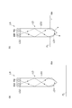
ところで、プラズマ処理装置に対して継続的又は断続的に水蒸気を供給するために、タンク内の液面高さが所定の高さを下回った場合に、タンク内に自動的に水を供給する構成を採用することが考えられる。このような構成は、タンク内の所定の高さ位置に水の接触状態を検出可能なセンサの先端部を配置することで実現が可能である。このセンサとしては、図13に示すようなセンサを利用することができる。 By the way, in order to continuously or intermittently supply water vapor to the plasma processing apparatus, when the liquid level in the tank falls below a predetermined height, water is automatically supplied into the tank. Can be considered. Such a configuration can be realized by arranging the tip of a sensor capable of detecting the contact state of water at a predetermined height position in the tank. As this sensor, a sensor as shown in FIG. 13 can be used.
図13に示すセンサLSは、ロッドLD、発光素子EM及び受光素子REを備えている。ロッドLDは、透光性の材料から構成されており、先端部LD1及び本体部LD3を有している。本体部LD3は、略円柱形状を有しており、先端部LD1は当該本体部LD3の一端に連続している。先端部LD1は、本体部LD3の他端、即ち基端部LD2から離れるにつれて縮径する円錐形状を有している。かかる形状を有するロッドLDは、図13に示すように、本体部LD3と先端部LD1との境界が基準位置RHに位置するように、配置される。この基準位置RHは、タンクの底部を基準とする高さ方向の位置である。なお、図13において、液面FLはタンク内の水面を表している。 A sensor LS shown in FIG. 13 includes a rod LD, a light emitting element EM, and a light receiving element RE. The rod LD is made of a translucent material and has a tip portion LD1 and a main body portion LD3. The main body portion LD3 has a substantially cylindrical shape, and the distal end portion LD1 is continuous with one end of the main body portion LD3. The distal end portion LD1 has a conical shape whose diameter decreases as the distance from the other end of the main body portion LD3, that is, the proximal end portion LD2. As shown in FIG. 13, the rod LD having such a shape is arranged so that the boundary between the main body portion LD3 and the tip portion LD1 is located at the reference position RH. This reference position RH is a position in the height direction with reference to the bottom of the tank. In FIG. 13, the liquid level FL represents the water surface in the tank.
図14は、先端部を含むロッドの一部の拡大断面図であり、ロッドLDの中心軸線Z1を含む平面において当該ロッドLDを切断して示す断面図である。先端部LD1は、先端角αを有している。図14に示すように、先端角αは、中心軸線Z1を含む断面において先端部LD1の表面が形成する二つの線(図中、参照符号「X」で示す)がなす角度として定義される。換言すると、先端角αは、中心軸線Zを含む平面と先端部LD1の表面との二つの交線がなす角度である。 FIG. 14 is an enlarged cross-sectional view of a part of the rod including the tip, and is a cross-sectional view showing the rod LD cut along a plane including the central axis Z1 of the rod LD. The tip portion LD1 has a tip angle α. As shown in FIG. 14, the tip angle α is defined as an angle formed by two lines (indicated by reference symbol “X” in the figure) formed by the surface of the tip portion LD1 in the cross section including the central axis Z1. In other words, the tip angle α is an angle formed by two intersecting lines between the plane including the central axis Z and the surface of the tip portion LD1.
図13に戻り、発光素子EM及び受光素子REは、基端部LD2上に設けられている。発光素子EMは、例えば発光ダイオードであり、受光素子REは、例えばフォトトランジスタである。発光素子EMは、基端部LD2に対して光を出射する。基端部LD2に入射した光は、先端部LD1に向かって本体部LD3を伝搬し、先端部LD1において反射される。先端部LD1において反射された光は、再び本体部LD3を伝搬し、基端部LD2を透過して、受光素子REによって受光される。受光素子REは、受光した光の強度に応じた電圧を出力する。即ち、受光素子REは、受光した光の強度が大きいほど、大きな電圧を出力する。 Returning to FIG. 13, the light emitting element EM and the light receiving element RE are provided on the base end LD2. The light emitting element EM is, for example, a light emitting diode, and the light receiving element RE is, for example, a phototransistor. The light emitting element EM emits light to the base end portion LD2. The light incident on the base end portion LD2 propagates through the main body portion LD3 toward the tip end portion LD1, and is reflected at the tip end portion LD1. The light reflected at the distal end portion LD1 propagates again through the main body portion LD3, passes through the proximal end portion LD2, and is received by the light receiving element RE. The light receiving element RE outputs a voltage corresponding to the intensity of the received light. That is, the light receiving element RE outputs a larger voltage as the intensity of the received light increases.
このセンサLSは、水と空気の屈折率の差を利用して、先端部LD1の水の接触状態を検知する。図13の(a)に示すように、先端部LD1が水に接していない場合、即ち、高さ方向において、液面FLが、基準位置RHよりも低い位置にある場合には、先端部LD1の屈折率と当該先端部LD1の表面に接する空気の屈折率の差が大きいので、先端部LD1において反射される光の量が多くなり、受光素子REによって受光される光の強度が大きくなる。一方、図13の(b)に示すように、先端部LD1が水と接している場合、即ち、液面FLが、基準位置RHと同一、又は、基準位置RHよりも高い位置にある場合には、先端部LD1の屈折率と当該先端部LD1の表面に接する水の屈折率との差が小さいので、先端部LD1から水に透過する光の量が大きくなり、受光素子REによって受光される光の強度が小さくなる。このように、先端部LD1が水に接しているか否かに応じて受光素子REで受光される光の強度が変化するので、センサLSは、受光素子REで受光した光の強度に基づいて、先端部LD1の水の接触状態を検知することができる。先端部LD1の水の接触状態を検知することができれば、タンク内の液面FLの高さ方向の位置が基準位置RHと同じ、又は、それよりも高い位置にあるか否かを検知することができる。 This sensor LS detects the contact state of water at the tip portion LD1 using the difference in refractive index between water and air. As shown in FIG. 13A, when the tip portion LD1 is not in contact with water, that is, when the liquid level FL is lower than the reference position RH in the height direction, the tip portion LD1. And the refractive index of the air in contact with the surface of the tip portion LD1 are large, the amount of light reflected at the tip portion LD1 increases, and the intensity of light received by the light receiving element RE increases. On the other hand, as shown in FIG. 13B, when the tip portion LD1 is in contact with water, that is, when the liquid level FL is the same as or higher than the reference position RH. Since the difference between the refractive index of the tip portion LD1 and the refractive index of water in contact with the surface of the tip portion LD1 is small, the amount of light that passes through the water from the tip portion LD1 increases and is received by the light receiving element RE. The light intensity decreases. Thus, since the intensity of the light received by the light receiving element RE changes depending on whether or not the tip portion LD1 is in contact with water, the sensor LS is based on the intensity of the light received by the light receiving element RE. The contact state of water at the tip portion LD1 can be detected. If it is possible to detect the water contact state of the tip portion LD1, it is detected whether the position in the height direction of the liquid level FL in the tank is the same as or higher than the reference position RH. Can do.
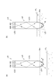
しかしながら、本願発明者は、図13に示すようなセンサを用いてタンク内の液面FLの高さ方向の位置が基準位置RHと同じ、又は、それよりも高い位置にあるか否かを検知しようとしたときに、次のような問題が生じることを発見した。例えば、図15の(a)に示すように、液面FLの高さ方向の位置が基準位置RHよりも低いときにタンク内の水を加熱すると、ロッドLDの先端部LD1に水滴Dが付着することがある。先端部LD1に水滴Dが付着すると、ロッドLDの屈折率と水滴Dの屈折率の差が小さいので、先端部LD1から水滴Dに透過する光の量が増加する。その結果、受光素子REによって受光される光の強度が小さくなり、液面FLの高さ方向の位置が基準位置RHよりも所定の距離以上低い位置にあるにも関わらず、液面FLの高さ方向の位置が基準位置RHと同じ、又は、それよりも高い位置にあると誤検知されることがある。 However, the inventor of the present application uses the sensor as shown in FIG. 13 to detect whether the position in the height direction of the liquid level FL in the tank is the same as or higher than the reference position RH. When I tried, I discovered the following problems. For example, as shown in FIG. 15A, when the water in the tank is heated when the position in the height direction of the liquid level FL is lower than the reference position RH, water droplets D adhere to the tip portion LD1 of the rod LD. There are things to do. When the water droplet D adheres to the distal end portion LD1, the difference between the refractive index of the rod LD and the refractive index of the water droplet D is small, so that the amount of light transmitted from the distal end portion LD1 to the water droplet D increases. As a result, the intensity of the light received by the light receiving element RE is reduced, and the height of the liquid level FL is high even though the position in the height direction of the liquid level FL is lower than the reference position RH by a predetermined distance or more. There is a case where the position in the vertical direction is erroneously detected as being at the same position as or higher than the reference position RH.
また、図15の(b)に示すように、液面FLの高さ方向の位置が基準位置RHよりも高い位置にあるときにタンク内の水を加熱すると、タンク内の水が沸騰してロッドLDの先端部LD1に気泡Bが付着することがある。先端部LD1に気泡Bが付着すると、ロッドLDの屈折率と気泡Bの屈折率の差が大きいので、先端部LD1から基端部LD2に向けて反射される光の量が増加する。その結果、受光素子REによって受光される光の強度が大きくなり、液面FLの高さ方向の位置が基準位置RHよりも所定の距離以上高い位置にあるにも関わらず、液面FLの高さ方向の位置が基準位置RHよりも低い位置にあると誤検知されることがある。これらの誤検知が発生すると、タンク内における液面FLの高さ方向の位置を正確に制御することができなくなる。 Further, as shown in FIG. 15B, when the water in the tank is heated when the position in the height direction of the liquid level FL is higher than the reference position RH, the water in the tank boils. Bubbles B may adhere to the tip portion LD1 of the rod LD. When the bubble B adheres to the distal end portion LD1, the difference between the refractive index of the rod LD and the refractive index of the bubble B is large, so that the amount of light reflected from the distal end portion LD1 toward the proximal end portion LD2 increases. As a result, the intensity of light received by the light receiving element RE is increased, and the height of the liquid level FL is high even though the position in the height direction of the liquid level FL is higher than the reference position RH by a predetermined distance or more. A false detection may be made when the vertical position is lower than the reference position RH. When these erroneous detections occur, the position of the liquid level FL in the height direction in the tank cannot be accurately controlled.
かかる背景から、タンク内の水との接触状態を検知するセンサの誤検知を抑制することが可能な気化器を有するプラズマ処理装置を提供することが要請されている。 From such a background, it is required to provide a plasma processing apparatus having a vaporizer that can suppress erroneous detection of a sensor that detects a contact state with water in a tank.
本発明の一態様に係るプラズマ処理装置は、気化器、プラズマ生成部、及び制御部を備える。気化器は、水蒸気を発生させる。プラズマ生成部は、気化器で発生した水蒸気のプラズマを生成する。気化器は、タンク、加熱器、少なくとも一つのセンサ、及び給水部を有している。タンクは、内部に水を貯留するための空間を画成している。加熱器は、タンク内の水を加熱して、水蒸気を発生させるよう構成されている。センサは、タンク内における水との接触状態に応じて異なる出力電圧を出力するよう構成されている。給水部は、タンク内に水を供給するよう構成されている。少なくとも一つのセンサは、ロッド、発光素子、フォトトランジスタ、出力回路、電源、及び増幅回路を有している。ロッドは、透光性を有しており、先端部及び基端部を有し、当該先端部と基端部の間で延在している。先端部は、タンクの空間内において高さ方向の所定位置に配置されている。基端部は、先端部の反対側に配置されている。先端部の先端角は、97°以上107°以下の角度に設定されている。発光素子は、ロッド内に伝搬させる光を基端部に対して出力する。フォトトランジスタは、基端部上に設けられており、発光素子から出力された光のうち、ロッドの先端部で反射された光を受光する。出力回路は、フォトトランジスタとグランド端子との間に設けられており、フォトトランジスタに直列に接続された抵抗素子を含む。この出力回路は、フォトトランジスタを流れる電流に応じた大きさの電圧を出力する。電源は、フォトトランジスタ及び抵抗素子を含む直列回路に入力電圧を印加する。増幅回路は、出力回路から出力される電圧を増幅し、増幅した該電圧を出力電圧として出力する。この気化器では、発光素子とフォトトランジスタとの間で光の損失がないと仮定したときに、電源が生成する入力電圧Vinと、増幅回路の出力電圧Voutとは、下記式(1);
|Vout|=|Gv・Vin| ・・・(1)
で表される関係を有する。式(1)においてGvはゲインである。この気化器では、ゲインは3200以上、14000未満の値に設定されている。制御部は、増幅回路の出力電圧に応じて、給水部からタンクに対する水の供給を制御するように構成されている。
A plasma processing apparatus according to one embodiment of the present invention includes a vaporizer, a plasma generation unit, and a control unit. The vaporizer generates water vapor. The plasma generation unit generates water vapor plasma generated by the vaporizer. The vaporizer includes a tank, a heater, at least one sensor, and a water supply unit. The tank defines a space for storing water inside. The heater is configured to generate water vapor by heating water in the tank. The sensor is configured to output different output voltages depending on the contact state with water in the tank. The water supply unit is configured to supply water into the tank. At least one sensor includes a rod, a light emitting element, a phototransistor, an output circuit, a power supply, and an amplifier circuit. The rod has translucency, has a distal end portion and a proximal end portion, and extends between the distal end portion and the proximal end portion. The tip is disposed at a predetermined position in the height direction in the space of the tank. The proximal end portion is disposed on the opposite side of the distal end portion. The tip angle of the tip is set to an angle of 97 ° to 107 °. The light emitting element outputs light propagating into the rod to the base end portion. The phototransistor is provided on the base end portion, and receives light reflected by the tip end portion of the rod among the light output from the light emitting element. The output circuit is provided between the phototransistor and the ground terminal, and includes a resistance element connected in series to the phototransistor. This output circuit outputs a voltage having a magnitude corresponding to the current flowing through the phototransistor. The power supply applies an input voltage to a series circuit including a phototransistor and a resistance element. The amplifier circuit amplifies the voltage output from the output circuit and outputs the amplified voltage as an output voltage. In this vaporizer, when it is assumed that there is no loss of light between the light emitting element and the phototransistor, the input voltage V in which power is generated, the output voltage V out of the amplifier circuit, the following formula (1) ;
| V out | = | Gv · V in | (1)
It has the relationship represented by. In Equation (1), Gv is a gain. In this vaporizer, the gain is set to a value of 3200 or more and less than 14000. The control unit is configured to control the supply of water from the water supply unit to the tank according to the output voltage of the amplifier circuit.
一態様に係るプラズマ処理装置では、ロッドの先端部が97°以上107°以下の先端角を有している。先端角を97°以上にすることで、ロッドの先端部が水に接していないときの出力電圧を大きくすることができる。これは、先端角を97°以上にすると、先端部において反射してフォトトランジスタによって受光される光の量が増加するためであると考えられる。また、先端角の上限値は107°である。この上限値は、先端部に付着した水滴が落下しやすくなるように規定された角度である。先端部に付着した水滴が落下することにより、水滴に起因するセンサの誤検知を減らすことができる。 In the plasma processing apparatus according to one aspect, the tip portion of the rod has a tip angle of 97 ° to 107 °. By setting the tip angle to 97 ° or more, the output voltage when the tip of the rod is not in contact with water can be increased. This is considered to be because when the tip angle is 97 ° or more, the amount of light reflected by the tip and received by the phototransistor increases. The upper limit value of the tip angle is 107 °. This upper limit value is an angle that is defined so that water droplets attached to the tip end part easily fall. When the water droplet attached to the tip portion falls, the erroneous detection of the sensor due to the water droplet can be reduced.
さらに、このプラズマ処理装置では、気化器のセンサのゲインが、3200以上14000未満に設定されている。ゲインを3200以上に設定することによって、液面の高さ方向の位置が上述の所定位置よりも低い位置にあるときに先端部に水滴が付着した場合であっても、センサの出力電圧を大きくすることができる。よって、先端部に付着した水滴に起因するセンサの誤検知を減らすことができる。一方、センサのゲインが14000以上であると、水中において先端部に気泡が付着したときにセンサの出力電圧が大きくなりすぎてしまい、誤検知が発生することがある。この気化器では、ゲインが14000未満に設定されているので、水中において先端部に気泡が付着したときに発生する誤検知を減らすことができる。故に、この気化器では、センサの誤検知を抑制することができる。一態様に係るプラズマ処理装置は、このような気化器を備えることで、タンク内の液面の高さ方向の位置が極端に高くなったり、低くなったりするような異常な状態になることを防止することができる。これにより、液面の高さが異常な状態となって装置が停止する事態を避けることができ、その結果、プラズマ処理装置の稼働率を向上することができる。 Further, in this plasma processing apparatus, the gain of the vaporizer sensor is set to 3200 or more and less than 14000. By setting the gain to 3200 or more, the output voltage of the sensor is increased even when water droplets adhere to the tip when the position in the height direction of the liquid level is lower than the above-mentioned predetermined position. can do. Therefore, erroneous detection of the sensor due to water droplets attached to the tip can be reduced. On the other hand, if the gain of the sensor is 14000 or more, the sensor output voltage becomes too large when bubbles are attached to the tip in water, and erroneous detection may occur. In this vaporizer, since the gain is set to less than 14000, it is possible to reduce erroneous detection that occurs when bubbles are attached to the tip in water. Therefore, in this vaporizer, the erroneous detection of the sensor can be suppressed. The plasma processing apparatus according to one aspect is provided with such a vaporizer, so that the liquid level in the tank is in an abnormal state where the position in the height direction becomes extremely high or low. Can be prevented. As a result, it is possible to avoid a situation where the liquid level becomes abnormal and the apparatus stops, and as a result, the operating rate of the plasma processing apparatus can be improved.
一実施形態では、制御部は、増幅回路の出力電圧が所定の閾値以上であるときに、タンク内に水が供給されるように給水部を制御してもよい。これにより、タンク内の液面の高さ方向の位置を適切に制御することが可能となる。また、一実施形態では、ロッドは、1.414以上、1.627以下の屈折率を有する材料から構成されていてもよい。さらに、一実施形態では、ロッドは石英から構成されていてもよい。 In one embodiment, the control unit may control the water supply unit so that water is supplied into the tank when the output voltage of the amplifier circuit is equal to or higher than a predetermined threshold value. Thereby, the position of the liquid surface in the height direction in the tank can be appropriately controlled. Moreover, in one Embodiment, the rod may be comprised from the material which has a refractive index of 1.414 or more and 1.627 or less. Furthermore, in one embodiment, the rod may be composed of quartz.
一実施形態では、前記少なくとも一つのセンサは、第1のセンサ及び第2のセンサを含み、第1のセンサの先端部は、高さ方向において第1の位置に配置され、第2のセンサの先端部は、高さ方向において第1の位置よりも高い第2の位置に配置されていてもよい。 In one embodiment, the at least one sensor includes a first sensor and a second sensor, and a distal end portion of the first sensor is disposed at a first position in the height direction, and the second sensor The distal end portion may be arranged at a second position higher than the first position in the height direction.
本発明の別の態様では、上記プラズマ処理装置の制御方法が提供される。この制御方法は、タンク内の水を加熱して水蒸気を発生させる工程と、水蒸気のプラズマを生成する工程と、少なくとも一つのセンサの出力電圧に基づいて、タンク内の水面の高さ方向の位置が所定位置よりも低い位置にあるか否かを判定する工程と、タンク内の水面の高さ方向の位置が所定位置よりも低い位置にあると判定された場合には、水面の高さ方向の位置が所定位置と同じに、又は、該所定位置よりも高くなるように給水部からタンク内に水を供給する工程と、を含む。 In another aspect of the present invention, a method for controlling the plasma processing apparatus is provided. This control method includes a step of heating water in the tank to generate water vapor, a step of generating water vapor plasma, and a position in the height direction of the water surface in the tank based on the output voltage of at least one sensor. In the height direction of the water surface when it is determined that the position of the water surface in the tank is lower than the predetermined position. Supplying the water from the water supply unit into the tank so that the position of the water is the same as the predetermined position or higher than the predetermined position.
このプラズマ処理装置の制御方法では、タンク内の液面の高さ方向の位置が所定位置よりも低くならないように制御される。これにより、タンク内の水位が極端に低くなることを防止することができる。 In this control method of the plasma processing apparatus, the position in the height direction of the liquid level in the tank is controlled so as not to be lower than a predetermined position. Thereby, it can prevent that the water level in a tank becomes extremely low.
本発明の更に別の態様では、プラズマ処理装置の制御方法が提供される。この制御方法は、第2のセンサの出力電圧に基づいて、タンク内の水面の高さ方向の位置が第2の位置よりも低い位置にあるか否かを判定する第1の工程と、水面の高さ方向の位置が第2の位置よりも低い位置にあると判定された場合には、水面の高さ方向の位置が第2の位置と同じに、又は、該第2の位置よりも高くなるように給水部からタンク内に水を供給する第2の工程と、タンク内の水を該タンクの外部に排出する第3の工程と、タンク内を減圧する第4の工程と、水面の高さ方向の位置が第1の位置と同じに、又は、該第1の位置よりも高くなるように給水部からタンク内に水を供給する第5の工程と、を含み、第5の工程よりも前に、第1の工程、第2の工程、第3の工程、及び、第4の工程を含むシーケンスを繰り返し実行する。 In still another aspect of the present invention, a method for controlling a plasma processing apparatus is provided. The control method includes a first step of determining whether or not the height direction position of the water surface in the tank is lower than the second position, based on the output voltage of the second sensor; When it is determined that the position in the height direction of the water is lower than the second position, the position in the height direction of the water surface is the same as the second position or is lower than the second position. A second step of supplying water into the tank from the water supply unit so as to be higher, a third step of discharging the water in the tank to the outside of the tank, a fourth step of decompressing the inside of the tank, and a water surface And a fifth step of supplying water into the tank from the water supply unit so that the position in the height direction is the same as the first position or higher than the first position. Prior to the process, a sequence including the first process, the second process, the third process, and the fourth process is repeatedly executed. .
この制御方法では、水面の高さ方向の位置が第2の位置と同じに、又は、該第2の位置よりも高くなるようにタンク内に水を供給し、その後タンク内から水を排出するシーケンスが繰り返し実施される。これにより、タンク内が洗浄され、タンク内のバクテリアが除去される。これにより、後工程で行われるプラズマ処理においてバクテリアに起因するコンタミネーションが被処理体に発生することを抑制することができる。 In this control method, water is supplied into the tank so that the position in the height direction of the water surface is the same as or higher than the second position, and then the water is discharged from the tank. The sequence is repeated. Thereby, the inside of a tank is wash | cleaned and the bacteria in a tank are removed. Thereby, it can suppress that the contamination resulting from bacteria generate | occur | produces in a to-be-processed object in the plasma processing performed at a post process.
本発明の一態様及び種々の実施形態によれば、センサの誤検知を抑制することが可能な気化器を有するプラズマ処理装置を提供することができる。 According to one aspect and various embodiments of the present invention, it is possible to provide a plasma processing apparatus having a vaporizer that can suppress erroneous detection of a sensor.
以下、図面を参照して種々の実施形態について詳細に説明する。なお、各図面において同一又は相当の部分に対しては同一の符号を附すこととする。 Hereinafter, various embodiments will be described in detail with reference to the drawings. In the drawings, the same or corresponding parts are denoted by the same reference numerals.
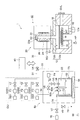
まず、一実施形態のプラズマ処理装置について説明する。図1は、一実施形態のプラズマ処理装置1を概略的に示す図である。図1に示すプラズマ処理装置1は、本体部10を備えている。
First, a plasma processing apparatus according to an embodiment will be described. FIG. 1 is a diagram schematically illustrating a
本体部10は、処理容器12を備えている。処理容器12は、ウエハWを収容するように構成されている。即ち、処理容器12は、ウエハWを収容するための空間S1を提供している。
The
一実施形態では、処理容器12は、第1部分12a及び第2部分12bを有している。第1部分12aは、略筒形状を有しており、処理容器12の側壁及び底部を構成している。この第1部分12aの上端は開口している。また、第2部分12bは、第1部分12aの上端に搭載されており、処理容器12の天井部を構成している。
In one embodiment, processing
処理容器12の内部には、載置台14が設けられている。載置台14は、その上に載置されるウエハWを保持するよう構成されている。一実施形態では、載置台14は、ウエハWを静電吸着するための静電チャックを有し得る。また、載置台14内には、ヒータHTが設けられている。ヒータHTは、処理容器12の外部に設けられたヒータ電源HPに電気的に接続されている。
A mounting table 14 is provided inside the
また、処理容器12の側壁には、ウエハWが通過し得る通路が形成されている。この通路を介して、ウエハWは処理容器12内に搬入され、また、処理容器12から外部に搬出される。処理容器12に形成された通路は、ゲートバルブGVLによって開閉可能となっている。
Further, a passage through which the wafer W can pass is formed in the side wall of the
また、処理容器12の底部には、排気口12eが形成されている。排気口12eには排気装置16が接続されている。排気装置16は、処理容器12内の空間S1及び後述する石英管22内の空間S2を減圧するよう構成されている。
Further, an
また、処理容器12内の空間S1には、プレート18が設けられている。このプレート18は、載置台14の上方に設けられており、当該載置台14の上面に対面している。プレート18は、多数の貫通孔が形成された板状体であり、例えば、石英から構成されている。
A
また、本体部10は、プラズマ発生ユニット20を更に備えている。プラズマ発生ユニット20は、処理容器12の天井部、即ち第2部分12b上に設けられている。このプラズマ発生ユニット20は、石英管22を有している。石英管22は、鉛直方向に延びる略筒形状を有しており、石英から構成されている。石英管22は、当該石英管22の内部の空間S2が空間S1と連通するように、処理容器12の天井部上に設けられている。
The
石英管22には、ガス導入口22aが形成されている。ガス導入口22aには、配管30の一端が接続されている。配管30の他端は、三方弁V4の第1ポートに接続されている。三方弁V4の第2ポートには、配管31の一端が接続されている。配管31の他端は、ガス供給部GUに接続されている。ガス供給部GUは、ガス供給系GSS1、ガス供給系GSS2、及び、ガス供給系GSS3を含んでいる。
A
ガス供給系GSS1は、ガス源GS1、流量制御器F1、及び、バルブV1を含み得る。ガス源GS1は、希ガスのガス源である。希ガスは、例えばArガスであるが、Heガス、Neガス、Krガス、Xeガスといった任意の希ガスであってもよい。流量制御器F1は、例えば、フローコントロールシステム(FCS)であり、ガス源GS1からの希ガスの流量を調整する。バルブV1は、ガス源GS1からの希ガスの供給及び供給停止を切り替える。ガス供給系GSS1は、本体部10の空間S2に希ガスを供給する。
The gas supply system GSS1 may include a gas source GS1, a flow rate controller F1, and a valve V1. The gas source GS1 is a rare gas source. The rare gas is, for example, Ar gas, but may be any rare gas such as He gas, Ne gas, Kr gas, or Xe gas. The flow rate controller F1 is, for example, a flow control system (FCS), and adjusts the flow rate of the rare gas from the gas source GS1. The valve V1 switches between supply and stop of supply of the rare gas from the gas source GS1. The gas supply system GSS1 supplies a rare gas to the space S2 of the
ガス供給系GSS2は、ガス源GS2、流量制御器F2、及び、バルブV2を含み得る。ガス源GS2は、O2ガスのガス源である。流量制御器F2は、例えば、フローコントロールシステムであり、ガス源GS2からのO2ガスの流量を調整する。バルブV2は、ガス源GS2からのO2ガスの供給及び供給停止を切り替える。ガス供給系GSS2は、本体部10の空間S2にO2ガスを供給する。
The gas supply system GSS2 may include a gas source GS2, a flow rate controller F2, and a valve V2. The gas source GS2 is a gas source of O 2 gas. The flow rate controller F2 is, for example, a flow control system, and adjusts the flow rate of O 2 gas from the gas source GS2. The valve V2 switches between supply and stoppage of O 2 gas from the gas source GS2. The gas supply system GSS2 supplies O 2 gas to the space S2 of the
ガス供給系GSS3は、ガス源GS3、流量制御器F3、及び、バルブV3を含み得る。ガス源GS3は、N2ガスのガス源である。流量制御器F3は、例えば、フローコントロールシステムであり、ガス源GS3からのN2ガスの流量を調整する。バルブV3は、ガス源GS3からのN2ガスの供給及び供給停止を切り替える。ガス供給系GSS3は、本体部10の空間S2、及び、後述する気化器50の空間S3にN2ガスを供給する。
The gas supply system GSS3 may include a gas source GS3, a flow rate controller F3, and a valve V3. The gas source GS3 is a gas source of N 2 gas. The flow rate controller F3 is, for example, a flow control system, and adjusts the flow rate of N 2 gas from the gas source GS3. The valve V3 switches between supply and stop of supply of N 2 gas from the gas source GS3. The gas supply system GSS3 supplies N 2 gas to the space S2 of the
また、プラズマ発生ユニット20は、プラズマ源を更に有している。一実施形態では、プラズマ発生ユニット20は、プラズマ源としてコイル24を有している。コイル24は、石英管22の外周面を囲むように設けられており、高周波電源RGに電気的に接続されている。コイル24に高周波電源RGからの高周波電力が与えられると、石英管22内の空間S2に供給されたガスが励起され、プラズマが生成される。このコイル24は、後述する気化器50で発生した水蒸気のプラズマを生成するプラズマ生成部として機能する。プラズマの生成により得られる活性種は、空間S2から空間S1に流れ、ウエハWに対して供給される。これにより、ウエハWに含まれる有機物又はウエハWに付着した有機物の除去等が行われる。なお、プラズマ発生ユニット20は筐体26を更に有しており、石英管22及びコイル24は、筐体26内に収容されている。
The
プラズマ処理装置1は、気化器50を更に備えている。気化器50は、プラズマ発生ユニット20に水蒸気、即ち気体状のH2Oを供給する機構である。気化器50は、タンク52を備えている。タンク52は、内部に水を貯留するための空間S3を画成している。タンク52の外側面には、温度センサTSが設けられている。温度センサTSは、例えば白金抵抗温度センサであり、タンク52内に貯えられている水の温度を測定する。タンク52の下方には、加熱器54が設けられている。加熱器54は、電源56に接続されおり、電源56から供給される電力によって発熱し、タンク52内の水を加熱する。加熱器54からの熱により水が加熱されると、タンク52内の水が気化して水蒸気が生成される。生成された水蒸気は、空間S3の上部に蓄えられる。タンク52の上部には、タンク52内の水蒸気を排出するための通気口58が設けられている。
The
通気口58には、配管32の一端が接続されている。配管32の他端は、配管33及び配管34に分岐している。配管33は、三方弁V4の第3ポートに接続されている。この三方弁V4は、配管31及び配管33の何れか一方を配管30に選択的に連通させるバルブである。即ち、三方弁V4は、ガス供給系GSS1,GSS2,GSS3からのガス、及び、気化器50からの水蒸気の何れか一方が本体部10の空間S2に選択的に供給されるように各ポートの接続を切り替える。また、配管32にはバルブV5が設けられており、配管33には流量制御器F4が設けられている。この流量制御器F4は、配管33を介して流量制御器F4に導入されたガスの流量に対して当該流量制御器F4を通過するガスの流量の割合(以下、「流量制御器通過率」という。)を0%〜100%の範囲で制御する機能を有している。配管32及び配管33は、気化器50から排出された水蒸気を、配管30を介して本体部10の空間S2に搬送する流路を提供する。
One end of the
配管34は、ガス供給系GSS3のガス源GS3に接続されている。この配管34には、バルブV6が設けられている。配管32及び配管34は、ガス源GS3からのN2ガスをタンク52内に搬送する流路を提供する。
The
また、気化器50は、第1のセンサ60a及び第2のセンサ60bを更に備えている。第1のセンサ60a及び第2のセンサ60bは、水との接触状態に応じて異なる出力電圧を出力する。この出力電圧は、後述するロッドの材質、液面からの距離、及び、ロッドの先端角度によって調整することが可能である。
The
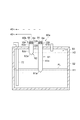
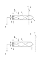
図2は、第1のセンサ60a及び第2のセンサ60bを概略的に示す図である。図2において、液面FLはタンク52内の水の水面を表している。第1のセンサ60aは、ロッド61及び回路部65を備えている。第2のセンサ60bは、ロッド62及び回路部66を備えている。ロッド61及びロッド62の各々は、透光性且つ長尺状の部材である。一実施形態では、ロッド61及びロッド62の各々は、1.414以上、1.627以下の屈折率を有する任意の材料から構成され得る。このような屈折率を有する材料としては、石英(屈折率:1.46)、蛋白石(屈折率:1.47)、蛍石(屈折率:1.43)、光学ガラス(屈折率:1.43)等が例示される。
FIG. 2 is a diagram schematically showing the
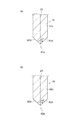
ロッド61は、先端部61a及び本体部61cを有している。本体部61cは、略円柱形状を有しており、タンク52の外部からタンク52の内部まで鉛直方向に延在している。先端部61aは、本体部61cの一端、即ち下端に連続している。先端部61aは、本体部61cの他端、即ち基端部61bから離れるにつれて縮径する円錐形状を有している。この先端部61aは、先端角α1を有している。図3の(a)は、先端部61aを含むロッド61の一部の拡大断面図であり、ロッド61の中心軸線Z2を含む平面において当該ロッド61を切断して示す断面図である。図3の(a)に示すように、先端角α1は、中心軸線Z2を含む断面において、先端部61aの表面が形成する二つの線(図中、参照符号「61X」で示す)がなす角度として定義される。換言すると、先端角α1は、中心軸線Z2を含む平面と先端部61aの表面との二つの交線61Xがなす角度である。この先端角α1は、97°以上107°以下の角度に設定されている。
The
ロッド61は、先端部61aがタンク52内に位置し、基端部61bがタンク52の外部に位置するように配置されている。ロッド61の本体部61cと先端部61aとの境界は、タンク52の底部を基準とする高さ方向において第1の基準位置(第1の位置)H1に配置されている。なお、一実施形態では、先端部61aの表面には研磨による鏡面加工が施されており、一方、本体部61cの表面には鏡面加工が施されていない。
The
ロッド61と同様に、ロッド62は、先端部62a及び本体部62cを有している。本体部62cは、略円柱形状を有しており、タンク52の外部からタンク52の内部まで鉛直方向に延在している。先端部62aは、本体部62cの一端、即ち下端に連続している。先端部62aは、本体部62cの他端、即ち基端部62bから離れるにつれて縮径する円錐形状を有している。この先端部62aは、先端角α2を有している。図3の(b)は、先端部62aを含むロッド62の一部の拡大断面図であり、ロッド62の中心軸線Z3を含む平面において当該ロッド62を切断して示す断面図である。図3の(b)に示すように、先端角α2は、中心軸線Z3を含む断面において、先端部62aの表面が形成する二つの線(図中、参照符号「62X」で示す)がなす角度として定義される。換言すると、先端角α2は、中心軸線Z3を含む平面と先端部62aの表面との二つの交線62Xがなす角度である。この先端角α2は、先端角α1と同一の角度であってもよいし、異なる角度であってもよい。
Similar to the
ロッド62は、先端部62aがタンク52内に位置し、基端部62bがタンク52の外部に位置するように配置されている。ロッド62の本体部62cと先端部62aとの境界は、タンク52の底部を基準とする高さ方向において第2の基準位置(第2の位置)H2に配置されている。この第2の基準位置H2は、第1の基準位置H1よりも上方の位置である。なお、図2では、ロッド62の長さがロッド61の長さよりも短いが、ロッド62はロッド61の長さと同一、又は、それ以上の長さを有していてもよい。
The
次に、第1のセンサ60a及び第2のセンサ60bが備える回路部について説明する。図2に示すように、第1のセンサ60aの回路部65は、フォトリフレクタ64を有している。フォトリフレクタ64は、発光素子104、及び、受光素子であるフォトトランジスタ106を含んでいる。発光素子104及びフォトトランジスタ106は、基端部61b上に設けられている。発光素子104は、基端部61bに対して光を出力する。基端部61bに入射した光は、本体部61c内で伝搬して先端部61aに入射する。先端部61aに入射した光の全部又は一部は反射される。先端部61aで反射された光は、本体部61c内で伝搬して基端部61bに向かい、フォトトランジスタ106によって受光される。フォトトランジスタ106は、受光した光の強度(光量)に応じた電流を出力する。そして、回路部65は、当該電流に応じた電圧を生成し、当該電圧を増幅して出力電圧を生成する。なお、第2のセンサ60bの回路部66は、第1のセンサ60aの回路部65と同一の回路構成及び機能を有している。以下では特に区別する必要があるときを除き、回路部66の説明は省略し、回路部65についてのみ説明する。
Next, the circuit units included in the
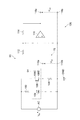
図4は、回路部65の回路構成の具体的な一例を示している。回路部65には、交流電源ACが設けられている。交流電源ACは、入力電圧Vinを生成する。交流電源ACの一方の端子は、抵抗素子102の一方の端子に接続されている。交流電源ACの他方の端子は、グランド端子GNDに接続されている。抵抗素子102の他方の端子は、発光素子104のアノードに接続されている。発光素子104のカソードはグランド端子GNDに接続されている。抵抗素子102及び発光素子104は、互いに直列に接続されている。この発光素子104は、例えば発光ダイオードであり、当該発光素子104に流れる電流に応じた強度を有する光を出射する。
FIG. 4 shows a specific example of the circuit configuration of the
また、回路部65は、フォトトランジスタ106を含んでいる。このフォトトランジスタ106は、抵抗素子102及び発光素子104からなる直列回路に対して並列に接続されている。フォトトランジスタ106のコレクタ端子106Cは、交流電源ACの一方の端子に接続されている。フォトトランジスタ106のエミッタ端子106Eは、当該フォトトランジスタ106に対して直列に接続された抵抗素子108の一方の端子に接続されている。抵抗素子108の他方の端子は、グランド端子GNDに接続されている。これらフォトトランジスタ106及び抵抗素子108を含む直列回路には、交流電源ACから入力電圧が印加される。このフォトトランジスタ106は、発光素子104から受光した光の強度に応じて、コレクタ端子106Cからエミッタ端子106Eに流れる電流を変化させる。具体的に、フォトトランジスタ106によって受光される光の強度が大きくなると、コレクタ端子106Cからエミッタ端子106Eに流れる電流が大きくなり、フォトトランジスタ106によって受光される光の強度が小さくなると、コレクタ端子106Cからエミッタ端子106Eに流れる電流が小さくなる。このフォトトランジスタ106に接続された抵抗素子108の両端間には、コレクタ端子106Cからエミッタ端子106Eに流れる電流に応じた電圧が発生する。即ち、フォトトランジスタ106によって受光される光の強度が大きくなるほど大きな電圧が抵抗素子108の両端間に発生する。
The
また、フォトトランジスタ106のエミッタ端子106E及び抵抗素子108の一方の端子には、第1の端子110aが接続されている。さらに、抵抗素子108の他方の端子には、第2の端子110bが接続されている。したがって、抵抗素子108の両端間の電圧は、第1の端子110aと第2の端子110bとの間の電圧Vceとして出力される。これら抵抗素子108、第1の端子110a及び第2の端子110bは、電圧Vceを出力するための出力回路70として機能している。なお、図4に示す回路例では、電圧Vceは入力電圧Vinよりも小さい。
The first terminal 110 a is connected to the
回路部65は、電圧Vceを増幅して、増幅した電圧を第3の端子118aと第4の端子118b間の出力電圧Voutとして出力する増幅回路120を更に有している。この増幅回路120は、抵抗素子112、抵抗素子114、及びオペアンプ116を有している。抵抗素子112の一方の端子は、上述の第1の端子110aに接続されている。抵抗素子112の他方の端子は、抵抗素子114の一方の端子に接続されており、且つ、オペアンプ116の反転入力端子に接続されている。抵抗素子114の他方の端子は、オペアンプ116の出力端子及び第3の端子118aに接続されている。オペアンプ116の非反転入力端子は、第2の端子110bに接続されており、且つ、第4の端子118bに接続されている。この第4の端子118bは、第2の端子110bに接続されている。
この回路部65では、抵抗素子112の抵抗値をRiとし、抵抗素子114の抵抗値をRfとしたときに、出力電圧Voutと電圧Vceとが、下記式(2)に示す関係を有する。即ち、増幅回路120は、電圧Vceに対して位相が反転した出力電圧Voutを出力する反転増幅回路である。
Vout=−(Rf/Ri)・Vce ・・・(2)
In the
V out = − (Rf / Ri) · V ce (2)
なお、増幅回路120は、電圧Vceを増幅して出力することができれば図4に示す反転増幅回路に限定されるものではない。例えば、増幅回路120として、電圧Vceと同位相の出力電圧Voutを出力する非反転増幅回路が用いられてもよい。また、一実施形態では、増幅回路120が整流回路を更に含み、当該整流回路が第3の端子118aと第4の端子118bとの間に発生する交流電圧を直流電圧に変換し、当該直流電圧が出力電圧Voutとして出力されてもよい。さらに、一実施形態では、交流電源ACに代えて直流電源が用いられてもよい。
Note that the
次に、第1のセンサ60a及び第2のセンサ60bの動作原理について説明する。第1のセンサ60a及び第2のセンサ60bは、互いに同一の機能及び特性を有しているので、以下では特に区別する必要があるときを除き、第1のセンサ60aについて説明する。図5の(a)は、タンク52内の液面FLの高さ方向の位置が第1の基準位置H1よりも低い状態、即ち、第1のセンサ60aの先端部61aが水中にない状態を示している。図5の(b)は、タンク52内の液面FLの高さ方向の位置が第1の基準位置H1よりも高い状態、即ち、第1のセンサ60aの先端部61aが水中にある状態を示している。
Next, the operation principle of the
図5の(a)及び(b)に示すように、フォトリフレクタ64の発光素子104から出射された光は、基端部61bから先端部61aに向けてロッド61内を伝搬する。先端部61aに到達した光の全部又は一部は、先端部61aにおいて反射される。先端部61aで反射された光は、基端部61bに向けて伝搬し、フォトトランジスタ106によって受光される。そして、フォトトランジスタ106を流れる電流に応じた出力電圧Voutが後述する制御部40に出力される。
As shown in FIGS. 5A and 5B, the light emitted from the
先端部61aにおいて反射される光の量は、先端部61aとの水との接触状態によって定まる。図5の(a)に示すように、先端部61aが水に接していない場合、即ち、高さ方向において、液面FLが第1の基準位置H1よりも低い位置にある場合には、先端部61aの屈折率と当該先端部61aの表面に接する空気の屈折率の差が大きいので、先端部61aにおいて反射される光の量が多くなり、フォトトランジスタ106によって受光される光の強度が大きくなる。一方、図5の(b)に示すように、先端部61aが水と接している場合、即ち、液面FLが第1の基準位置H1と同一、又は、第1の基準位置H1よりも高い位置にある場合には、先端部61aの屈折率と当該先端部61aの表面に接する水の屈折率との差が小さいので、先端部61aから水に透過する光の量が大きくなり、フォトトランジスタ106によって受光される光の強度が小さくなる。このように、先端部61aにおいて反射される光の量が先端部61aの水との接触状態に応じて増減するので、第1のセンサ60aの回路部65から出力される出力電圧Voutを所定の閾値と比較することによって、先端部61aが水に接触しているか否かを判別することが可能となる。
The amount of light reflected at the
また、先端部61aにおいて反射される光の量は、先端部61aの先端角α1にも依存する。一例として、中心軸線Z2に平行な方向に進行して先端部61aの表面に入射する光について考える。この光は、先端部61aの表面にα1/2の入射角で入射する。例えば先端部61aの先端角α1が90°であるときには、先端部61aに入射した光は、先端部61aの表面において45°の反射角で2回反射し、中心軸線Z2に平行な方向に沿って先端部61aから基端部61bに向けて再び進行する。このような反射をしたときに、先端部61aの表面で生じる光の損失は最も小さくなる。即ち、発光素子104から中心軸線Z2に平行な方向に進行する光が出射されたときには、先端部61aの先端角α1を90°に設定するとフォトトランジスタ106において受光される光の量が最も大きくなる。
Further, the amount of light reflected at the
しかしながら、実際には、発光素子104から出射し、先端部61aに向けて本体部61cを進行する光は発散光であり、中心軸線Z2に平行な方向に進行する成分のみでなく、様々な角度成分を有する光である。具体的に、先端部61aに向けて本体部61cを進行する光の強度分布は、角度方向においてガウス分布を有している。このような発散光は、先端角α1を90°以上に設定することで、先端部61aにおいて効率よく反射されるものと推測される。上述したように、先端部61aの先端角α1は97°以上の角度を有しているので、発光素子104から出射された光を先端部61aにおいて効率よく反射することができる。また、先端角α1は107°以下である。先端角α1を107°以下にすることにより、先端部61aに付着した水滴が落下しやすくなる。
However, in reality, the light emitted from the
次に、第1のセンサ60aの特性について説明する。第1のセンサ60aにおいて、発光素子104とフォトトランジスタ106との間で光の損失がないと仮定したときに、入力電圧Vinと、回路部65の出力電圧Voutとは、下記式(1)で表される関係を有している。下記式(1)において、Gvは第1のセンサ60aのゲインを表している。式(1)に示すように、ゲインGvを大きく設定することで、一定の入力電圧Vinに対する出力電圧Voutが増加する。このゲインGvは、抵抗素子112の抵抗値Ri、及び、抵抗素子114の抵抗値Rfを変更することによって調整することが可能である。
Next, the characteristics of the
|Vout|=|Gv・Vin| ・・・(1) | V out | = | Gv · V in | (1)
第1のセンサ60aでは、式(1)に示すゲインGvが、3200以上、14000未満に設定されている。ゲインを3200以上に設定することによって、液面FLの高さ方向の位置が第1の基準位置H1よりも低いときに、先端部61aに水滴が付着した場合であっても、出力電圧Voutを大きくすることができる。よって、先端部61aに水滴が付着したときに出力電圧Voutが所定の閾値を下回ることが抑制され、その結果、先端部61aに付着した水滴に起因するセンサの誤検知を抑制することができる。一方、ゲインを14000以上に設定すると、水中において先端部61aに気泡が付着したときに、出力電圧Voutが大きくなりすぎてしまい、誤検知が発生することがある。第1のセンサ60aでは、ゲインが14000未満に設定されているので、出力電圧Voutが過剰に大きくなることが抑制され、その結果、水中において先端部61aに付着した気泡に起因する誤検知を抑制することができる。また、上述したように、第2のセンサ60bは、第1のセンサ60aと同様の構成、機能及び特性を有している。よって、第2のセンサ60bでも、先端部62aに付着した水滴に起因するセンサの誤検知を抑制することができ、且つ、水中において先端部62aに付着した気泡に起因する誤検知を抑制することができる。
In the
再び図1を参照する。図1に示すように、タンク52には導管72が設けられている。導管72は、その先端が空間S3の下部に位置するようにタンク52の外部からタンク52の内部まで略鉛直方向に延在している。導管72には、配管74の一端が接続されている。配管74の他端には、給水部76が接続されている。給水部76は、給水用の水を貯留しており、配管74を介して水をタンク52内に供給する。配管74の途中位置にはバルブV7が設けられている。バルブV7は、給水部76からタンク52に対する水の供給及び供給停止を切り替える。また、バルブV7よりも配管74の一端に近い配管74上の位置には、排水管78が接続されている。排水管78は、導管72及び配管74を介してタンク52から排出された水を気化器50の外部に排出する。また、排水管78の途中位置にはバルブV8が設けられている。バルブV8は、タンク52内の水の排出、及び、排出停止を切り替える。
Refer to FIG. 1 again. As shown in FIG. 1, a
さらに、プラズマ処理装置1は、制御部40を備えている。制御部40は、プラズマ処理装置1の各部を制御する。制御部40は、例えば、プロセッサ、記憶装置、入力装置、表示装置等を備えるコンピュータであり得る。制御部40は、プラズマ処理装置1の各部を制御するためのプログラムを記憶装置に格納しており、当該プログラムを実行することにより、プラズマ処理装置1の各部、例えば、バルブV1〜V3,V5〜V8、三方弁V4、流量制御器F1〜F4、高周波電源RG、ヒータ電源HP、排気装置16、及び、電源56を制御する。一例では、制御部40は、第1のセンサ60a及び第2のセンサ60bから出力される出力電圧Voutに応じて、給水部76からタンク52に対する水の供給を制御する。
Further, the
次に、一実施形態のプラズマ処理装置1の制御方法について説明する。図6は、希ガス、O2ガス、及び、N2ガスのプラズマによってウエハWをプラズマ処理するためのプラズマ処理装置1の制御方法MT1を示す流れ図である。
Next, the control method of the
制御方法MT1では、まず工程ST1において、ガス供給部GUからO2ガス、N2ガス、及び、希ガスが石英管22内の空間S2に供給される。これらのガスを空間S2に供給するために、制御部40は、バルブV1〜V3を開放し、バルブV5〜V8を閉鎖する。また、制御部40は、配管31が配管30に対して連通されるように三方弁V4を制御する。このように各バルブが制御されることにより、ガス供給部GUからのO2ガス、N2ガス、及び、希ガスが、配管31及び配管30を通って空間S2に供給される。
In the control method MT1, first, in step ST1, O 2 gas, N 2 gas, and rare gas are supplied from the gas supply unit GU to the space S2 in the
次いで、制御方法MT1では、工程ST2が行われる。工程ST2では、O2ガス、N2ガス、及び、希ガスのプラズマが生成される。このために、工程ST2では、高周波電源RGからコイル24に高周波電力が与えられる。この高周波電力によって、空間S2において、O2ガス、N2ガス、及び、希ガスのプラズマが生成される。そして、このプラズマの活性種によって、ウエハWに含まれる有機物、及び/又はウエハWに付着した有機物が除去される。即ち、アッシング処理が行われる。
Next, in the control method MT1, step ST2 is performed. In step ST2, plasma of O 2 gas, N 2 gas, and rare gas is generated. For this reason, in step ST2, high frequency power is applied to the
次に、プラズマ処理装置1の別の制御方法について説明する。図7は、H2Oガス、即ち水蒸気のプラズマによってウエハWをプラズマ処理するためのプラズマ処理装置1の制御方法MT2を示す流れ図である。
Next, another control method of the
制御方法MT2では、まず工程ST11において、タンク52内の水の温度が設定温度に制御される。この設定温度は、タンク52の容量、配管30,32の内径及び長さ、並びに、空間S2に供給されるべきH2Oガスの流量によって定まる温度であり、例えば摂氏50度〜78度である。タンク52内の水の温度を制御するために、制御部40は電源56に制御信号を送信し、加熱器54で生じる熱量を制御する。タンク52内の水の温度が設定温度になると、次いで工程ST12が行われる。工程ST12では、気化器50からH2Oガスが石英管22内の空間S2に供給される。工程ST12では、H2Oガスを空間S2に供給するために、制御部40は、バルブV5を開放し、バルブV1〜3,V6〜V8を閉鎖する。また、制御部40は、配管33が配管30に連通されるように三方弁V4を制御する。このように各バルブが制御されることにより、空間S3内のH2Oガスが配管32、配管33及び配管30を通って空間S2に供給される。
In the control method MT2, first, in step ST11, the temperature of the water in the
次いで、制御方法MT2では、工程ST13が行われる。工程ST13では、H2Oガスのプラズマが生成される。このために、工程ST13では、高周波電源RGからコイル24に高周波電力が与えられる。この高周波電力によって、空間S2において、H2Oガスのプラズマが生成される。そして、このプラズマの活性種によって、ウエハWに含まれる有機物、及び/又はウエハWに付着した有機物が除去される。即ち、アッシング処理が行われる。
Next, in the control method MT2, step ST13 is performed. In step ST13, plasma of H 2 O gas is generated. For this reason, in step ST13, high frequency power is applied to the
次いで、制御方法MT2では、工程ST14が行われる。工程ST14では、タンク52内の液面FLの高さ方向の位置が第1の基準位置H1よりも低いか否かが判定される。制御部40は、第1のセンサ60aの出力電圧Voutの実効値(以下、単に「出力電圧Vout」という。)が所定の閾値以上であるときに、液面FLの高さ方向の位置が第1の基準位置H1よりも低いと判定する。工程ST14において、液面FLの高さ方向の位置が第1の基準位置H1よりも低いと判定された場合、即ち、第1のセンサ60aの出力電圧Voutが所定の閾値以上であると判定された場合には、工程ST15が行われる。工程ST15では、液面FLの高さ方向の位置が第1の基準位置H1と同じに、又は、第1の基準位置H1よりも高くなるように給水部76からタンク52に水が供給される。タンク52内に水を供給するために、制御部40はバルブV7に制御信号を送信し、バルブV7を開放する。これにより、給水部76に貯留された水が配管74及び導管72を介してタンク52内に供給される。また、制御部40は、液面FLの高さ方向の位置が第1の基準位置H1と同じ、又は、第1の基準位置H1よりも高くなると、バルブV7を閉鎖してタンク52に対する給水を停止する。
Next, in the control method MT2, step ST14 is performed. In step ST14, it is determined whether or not the position in the height direction of the liquid level FL in the
一方、工程ST14において液面FLの高さ方向の位置が第1の基準位置H1と同じ、又は、それよりも高い位置にあると判定されたときには、工程ST16が行われる。また、工程ST15において給水部76からタンク52に水が供給された場合にも、工程ST16が行われる。この工程ST16では、終了条件が満たされたか否かが判定される。例えば、工程ST16では、工程ST13のアッシング処理が所定回数以上実施されたか否かが判定される。工程ST16において、終了条件が満たされていないと判定されたときには、工程ST11が再び行われる。一方、工程ST16において、終了条件が満たされたと判定されたときには、処理を終了する。
On the other hand, when it is determined in step ST14 that the position in the height direction of the liquid surface FL is the same as or higher than the first reference position H1, step ST16 is performed. Further, the process ST16 is also performed when water is supplied from the
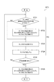
次に、プラズマ処理装置1の更に別の制御方法について説明する。図8は、タンク52内を洗浄するためのプラズマ処理装置1の制御方法MT3を示す流れ図である。プラズマ処理装置1が長期間停止されたときなど、タンク52内の水の温度制御が行われなくなるとタンク52内の水の温度が常温まで低下し、タンク52内にバクテリアが発生することがある。この状態からタンク52内の水を加熱し、タンク52内に発生した水蒸気を用いてウエハWにプラズマ処理を実施すると、ウエハWにコンタミネーションが発生することがある。このコンタミネーションを抑制するために、制御方法MT3ではタンク52内が洗浄される。この制御方法MT3は、例えばプラズマ処理装置1が起動されたタイミングで実施される。
Next, still another control method of the
制御方法MT3では、シーケンスSQが繰り返し実行される。シーケンスSQは、工程ST21(第1の工程)、工程ST22(第2の工程)、工程ST23(第3の工程)、及び、工程ST24(第4の工程)を含んでいる。シーケンスSQでは、まず工程ST21において、タンク52内の液面FLの高さ方向の位置が第2の基準位置H2よりも低い位置にあるか否かが判定される。制御部40は、第2のセンサ60bの出力電圧Voutが所定の閾値以上であるときに、タンク52内の液面FLの高さ方向の位置が第2の基準位置H2よりも低いと判定する。工程ST21においてタンク52内の液面FLの高さ方向の位置が第2の基準位置H2よりも低いと判定された場合には、工程ST22が行われる。工程ST22では、液面FLの高さ方向の位置が第2の基準位置H2と同じに、又は、第2の基準位置H2よりも高くなるように給水部76からタンク52に水が供給される。タンク52内に水を供給するために、制御部40はバルブV7に制御信号を送信し、バルブV7を開放する。これにより、給水部76に貯留された水が配管74及び導管72を介してタンク52内に供給される。また、制御部40は、液面FLの高さ方向の位置が第2の基準位置H2と同じ、又は、第2の基準位置H2よりも高くなると、バルブV7を閉鎖してタンク52に対する給水を停止する。
In the control method MT3, the sequence SQ is repeatedly executed. The sequence SQ includes a process ST21 (first process), a process ST22 (second process), a process ST23 (third process), and a process ST24 (fourth process). In the sequence SQ, first, in step ST21, it is determined whether or not the position in the height direction of the liquid level FL in the
工程ST22においてタンク52内に給水が行われると、次いで工程ST23が行われる。工程ST23では、タンク52内の水が排水される。タンク52内の水を排出するために、制御部40はバルブV7を閉鎖させたまま、バルブV5,V6,V8を開放する。これにより、ガス源GS3からのN2ガスが通気口58を介してタンク52内に供給され、タンク52内の圧力が上昇する。これに伴い、タンク52の内部と外部との間で圧力差が生じ、タンク52内の水が導管72を介して相対的に低圧なタンク52の外部に排出される。タンク52から排出された水は、排水管78を介して気化器50の外部に排水される。
When water is supplied into the
タンク52から水が排出されると、次いで工程ST24が行われる。工程ST24では、タンク52内の空間S3が減圧される。タンク52内を減圧するために、制御部40はバルブV6,V7,V8を閉鎖し、バルブV5を開放する。また、制御部40は配管33が配管30に連通するように三方弁V4を制御する。これにより、空間S2と空間S3とが連通され、タンク52内が減圧される。
When water is discharged from the
次いで、工程ST25が行われる。工程ST25では、シーケンスSQ、即ち工程ST21〜ST24の実行回数が所定回数に達したか否かが判定される。工程ST25においてシーケンスSQの実行回数が所定回数に達していないと判定された場合には、所定回数に達するまでシーケンスSQが繰り返し実行される。一例では、シーケンスSQは30回繰り返し実行される。一方、工程ST25においてシーケンスSQの実行回数が所定回数に達したと判定された場合には、次いで工程ST26(第5の工程)が行われる。 Next, step ST25 is performed. In step ST25, it is determined whether or not the number of executions of the sequence SQ, that is, steps ST21 to ST24, has reached a predetermined number. If it is determined in step ST25 that the number of executions of the sequence SQ has not reached the predetermined number, the sequence SQ is repeatedly executed until the predetermined number of times is reached. In one example, the sequence SQ is repeatedly executed 30 times. On the other hand, if it is determined in step ST25 that the number of executions of the sequence SQ has reached the predetermined number, then step ST26 (fifth step) is performed.
工程ST26では、液面FLの高さ方向の位置が第1の基準位置H1と同じ、又は、第1の基準位置H1よりも高くなるように給水部76からタンク52に水が供給される。タンク52内に水を供給するために、制御部40はバルブV7に制御信号を送信し、バルブV7を開放する。これにより、給水部76に貯留された水が配管74及び導管72を介してタンク52内に供給される。また、制御部40は、液面FLの高さ方向の位置が第1の基準位置H1と同じ、又は第1の基準位置H1よりも高くなると、バルブV7を閉鎖してタンク52に対する給水を停止する。図8に示す制御方法MT3では、シーケンスSQを繰り返し実行することによってタンク52内に発生したバクテリアが除去される。なお、制御方法MT3が行われた後、制御方法MT1又は制御方法MT2が必要に応じて実行され得る。
In step ST26, water is supplied from the
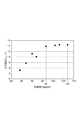
次に、先端部61aの先端角に関する実験結果について説明する。図9は、先端部61aが完全に空気と接している場合における、先端部61aの先端角と出力電圧Voutとの関係を示す実験結果である。図9に示すように、先端部61aの先端角が80°以上97°未満の範囲内の角度である場合には、先端部61aの先端角が大きくなるほど出力電圧Voutが大きくなることが確認された。一方、先端部61aの先端角が97°以上107°以下の範囲内の角度である場合では、先端部61aの先端角が大きくなっても出力電圧Voutは略一定となることが確認された。この結果は、図4に示すように、フォトトランジスタ106及び抵抗素子108を含む直列回路に入力電圧Vinが印加されているので、抵抗素子108の両端子間に発生する電圧Vceが入力電圧Vinを超えないことに起因するものと推察される。
Next, experimental results regarding the tip angle of the
上記結果から、先端部61aの先端角を97°以上にすることで、先端部61aが空気と接しているときのセンサの出力電圧Voutが大きくなることが確認された。この結果は、先端角を97°以上にすることによって、先端部61aにおいて反射されフォトトランジスタによって受光される光の量が増加したために得られたものであると考えられる。よって、先端部61aの先端角を97°以上にすることで、タンク52内の液面FLが第1の基準位置H1よりも低い位置にあるときにロッド61の先端部61aに水滴が付着したとしても、センサの出力電圧Voutを大きなものにすることができる。これにより、先端部61aに水滴が付着した場合であっても出力電圧Voutが所定の閾値を下回りにくくなるので、水滴の付着に起因するセンサの誤検知を抑制することが可能となる。また、ロッド62の先端部61aの先端角を107°以下にすることにより、先端部61aに付着した水滴が落下しやすくなる。よって、先端部61aに水滴が付着することを抑制することができる。
From the above results, it was confirmed that the output voltage Vout of the sensor when the
次に、第1のセンサ60aのゲインGvに関する実験結果について説明する。この実験結果を得た実験では、先端部61aにおける光の全反射を模擬的に発生させるために、第1のセンサ60aからロッド61を取り外し、フォトリフレクタ64の直下に反射率が互いに異なる黄色及び紫色の色紙を配置した状態で発光素子104から光を出射させた。そして、これらの色紙が配置されたときに回路部65から出力された出力電圧Voutをそれぞれ測定した。図10は、実験において得られた出力電圧VoutとゲインGvとの関係を示す図である。図10に示すように、回路部65のゲインGvを増加させていくと、ある値以上のゲインGvに対して出力電圧Voutが飽和して略一定となっていた。ここで、ゲインが4倍になったときに出力電圧Voutの増加率が11%以内となるゲインGvの範囲を平坦範囲と定義すると、平坦範囲の下限であるゲインGvは3200となる。図10に示すように、第1のセンサ60aのゲインGvを平坦範囲に含まれる値に設定した場合には、回路部65の直下に何れの色紙が配置された場合であっても、大きな出力電圧Voutが出力されることが確認された。即ち、第1のセンサ60aのゲインGvを3200以上に設定することにより、先端部61aにおける反射率が低く当該先端部61aの表面で光の損失が生じる場合でも、第1のセンサ60aから大きな出力電圧Voutが出力させることができることが確認された。このことから、先端部61aに水滴が付着しており、当該先端部61aの表面から水滴に光が漏れて光の損失が生じる場合でも、第1のセンサ60aから大きな出力電圧Voutが出力させることができることが確認された。
Next, experimental results regarding the gain Gv of the
次に、加熱器54によりタンク52内の水を加熱し、タンク52から石英管22内の空間S2に水蒸気が間欠的に供給されるように流量制御器F4を制御した。そして、第1のセンサ60aの判定結果の経時的変化を得た。図11の(a)〜(c)の上段のグラフは、第1のセンサ60aのゲインGvをそれぞれ1400、3200、6500に設定したときの、第1のセンサ60aの判定結果の経時的変化を示している。これらのグラフにおいて、縦軸は先端部61aの水の接触状態の判定結果であり、横軸は時間である。図11の上段のグラフに示される判定結果の「1」とは、制御部40において先端部61aが水に接触していると判定されたことを示しており、判定結果の「0」とは、制御部40において先端部61aが水に接触していないと判定されたことを示している。このように、制御部40は、第1のセンサ60aからの出力電圧Voutを所定の閾値に基づいて二値化することによって、先端部61aに対する水の接触状態を判別している。また、図11の(a)〜(c)の下段のグラフは、流量制御器通過率の経時的な変化を示している。これらのグラフにおいて、縦軸は水蒸気の流量制御器通過率であり、横軸は時間である。なお、図11の(a)〜(c)の上段のグラフの横軸の時間及び下段のグラフの横軸の時間は、互いに一致している。
Next, the water in the
図11の(a)〜(c)の上段のグラフで示すように、本実験では、時間が46分のときに第1のセンサ60aの判定結果が「0」から「1」に変化している。これは、タンク52内に水が供給されたことを示している。本実験では、その後はタンク52内に水の供給が行われないようにした。その結果、図11の(a)〜(c)の上段のグラフでは、時間が65分になったときに第1のセンサ60aの判定結果が「1」から「0」に変化した。
As shown in the upper graphs of FIGS. 11A to 11C, in this experiment, when the time is 46 minutes, the determination result of the
その後も観測を続けたところ、図11の(a)の上段のグラフで示すように、ゲインGvを1400に設定した場合には、時間が71分になったところで第1のセンサ60aの判定結果が「0」から「1」に再び変化した。本実験では、46分の給水以降はタンク52内に水の供給が行われないようにしていたので、時間が71分になったときには第1のセンサ60aの先端部61aに水は接触していなかったはずである。したがって、時間が71分になったときに、先端部61aが水に接触しているという判定は誤検知であると判断される。図11の(a)の下段のグラフを参照すると、この誤検知は、流量制御器通過率が100%から0%に変化した直後に発生していることが分かる。流量制御器通過率が100%から0%に変化すると、タンク52内の空間S3と処理容器12内の空間S2との連通が解除されるのでタンク52内の圧力が上昇する。これに伴い、タンク52内の水蒸気は液化し易くなる。これらの結果から、この誤検知は、タンク52内の圧力が上昇してロッド61の先端部61aに水滴が付着したことに起因して発生したものであると推認される。一方、図11の(b)及び(c)に示すように、第1のセンサ60aのゲインGvを3200又は6500に設定した場合には、流量制御器通過率の変化に関わらず、65分以降の判定結果が「0」のままであった。即ち、誤検知は確認されなかった。
When the observation is continued thereafter, as shown in the upper graph of FIG. 11A, when the gain Gv is set to 1400, the determination result of the
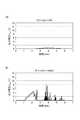
次に、図12を参照する。図12は、タンク52内の液面FLが第1の基準位置H1よりも高い位置にある状態で、加熱器54を用いてタンク52内の水を加熱したときに、第1のセンサ60aから出力された出力電圧Voutの経時的変化を示す図である。図12の(a)は、第1のセンサ60aのゲインGvを180に設定したときの結果であり、図12の(b)は、第1のセンサ60aのゲインGvを14000に設定したときの結果である。ここで先端部61aに水が接触しているか否かを判定するための閾値は6Vとした。
Reference is now made to FIG. FIG. 12 shows the
第1のセンサ60aのゲインGvが180である場合には、図12の(a)に示すように、水の加熱によって気泡が発生しても、第1のセンサ60aの出力電圧Voutは大きく増加しなかった。一方、第1のセンサ60aのゲインGvが14000である場合には、水の加熱によって生じる気泡の影響により、第1のセンサ60aの出力電圧Voutは大きく増加した。この出力電圧Voutは、連続的に6Vを超過することはなかったものの、瞬間的に6Vを超過した。この結果から、ゲインGvを14000以上に設定した場合には、水中において先端部61aに気泡が付着したときに誤検知が生じる可能性が高いことが確認された。しかし、第1のセンサ60aのゲインGvが14000である場合には、出力電圧Voutは連続的に6Vを超えることはなかったので、第1のセンサ60aのゲインGvを14000未満に設定した場合には第1のセンサ60aに誤検知が発生する可能性を低くすることができると考えられる。
When the gain Gv of the
以上、一実施形態に係るプラズマ処理装置について説明してきたが、上述した実施形態に限定されることなく種々の変形態様を構成可能である。例えば、プラズマ処理装置1は、コイル24を用いる誘導結合方式のプラズマ処理装置に限定されるものではない。プラズマ処理装置1としては、任意のプラズマ処理装置、例えば、マイクロ波といった表面波によってプラズマを生成するプラズマ処理装置を用いることが可能である。
Although the plasma processing apparatus according to the embodiment has been described above, various modifications can be made without being limited to the above-described embodiment. For example, the
1…プラズマ処理装置、10…本体部、40…制御部、50…気化器、52…タンク、54…加熱器、60a…第1のセンサ、60b…第2のセンサ、61,62…ロッド、61a,62a…先端部、61b,62b…基端部、61X,62X…交線、64…フォトリフレクタ、65,66…回路部、70…出力回路、72…導管、76…給水部、102…抵抗素子、104…発光素子、106…フォトトランジスタ、106C…コレクタ端子、106E…エミッタ端子、108…抵抗素子、120…増幅回路、FL…液面、GND…グランド端子、S3…空間、α1,α2…先端角。
DESCRIPTION OF
Claims (6)
前記気化器で発生した前記水蒸気のプラズマを生成するプラズマ生成部と、
制御部と、
を備え、
前記気化器は、
内部に水を貯留するための空間を画成するタンクと、
前記タンク内の水を加熱して、前記水蒸気を発生させる加熱器と、
前記タンク内における水との接触状態に応じて異なる出力電圧を出力する少なくとも一つのセンサと、
前記タンク内に水を供給する給水部と、
を有し、
前記少なくとも一つのセンサは、
前記空間内において高さ方向の所定位置に配置された先端部、及び、前記先端部の反対側に配置された基端部を有し、該先端部と該基端部との間で延在する透光性のロッドであり、前記先端部の先端角が97°以上107°以下である、該ロッドと、
前記ロッド内に伝搬させる光を前記基端部に対して出力する発光素子と、
前記基端部上に設けられ、前記発光素子から出力された光のうち、前記ロッドの先端部で反射された光を受光するフォトトランジスタと、
前記フォトトランジスタとグランド端子との間に設けられ、前記フォトトランジスタに直列に接続された抵抗素子を含む出力回路であり、前記フォトトランジスタを流れる電流に応じた大きさの電圧を出力する該出力回路と、
前記フォトトランジスタ及び前記抵抗素子を含む直列回路に入力電圧を印加する電源と、
前記出力回路から出力される電圧を増幅し、増幅した該電圧を前記出力電圧として出力する増幅回路と、
を含み、
前記発光素子と前記フォトトランジスタとの間で光の損失がないと仮定したときに、前記電源が生成する前記入力電圧Vinと、前記増幅回路の前記出力電圧Voutとは、下記式(1);
|Vout|=|Gv・Vin| ・・・(1)
で表される関係を有し、
式(1)において、Gvはゲインであり、該ゲインは3200以上、14000未満であり、
前記制御部は、前記増幅回路の前記出力電圧に応じて、前記給水部から前記タンクに対する水の供給を制御し、
前記ロッドは、石英から構成されている、プラズマ処理装置。 A vaporizer that generates water vapor;
A plasma generating section for generating plasma of the water vapor generated in the vaporizer;
A control unit;
With
The vaporizer is
A tank defining a space for storing water inside,
A heater for heating the water in the tank to generate the water vapor;
At least one sensor that outputs different output voltages depending on the contact state with water in the tank;
A water supply unit for supplying water into the tank;
Have
The at least one sensor comprises:
A distal end portion disposed at a predetermined position in the height direction in the space and a proximal end portion disposed on the opposite side of the distal end portion, and extending between the distal end portion and the proximal end portion A translucent rod that has a tip angle of 97 ° or more and 107 ° or less at the tip, and
A light emitting element that outputs light propagating into the rod to the base end;
A phototransistor that is provided on the base end and receives light reflected from the tip of the rod out of the light output from the light emitting element;
An output circuit including a resistance element provided between the phototransistor and a ground terminal and connected in series to the phototransistor, wherein the output circuit outputs a voltage having a magnitude corresponding to a current flowing through the phototransistor. When,
A power supply for applying an input voltage to a series circuit including the phototransistor and the resistive element;
An amplifying circuit for amplifying a voltage output from the output circuit and outputting the amplified voltage as the output voltage;
Including
When it is assumed that there is no loss of light between the light emitting element and the phototransistor, the input voltage V in generated by the power supply and the output voltage V out of the amplifier circuit are expressed by the following formula (1) );
| V out | = | Gv · V in | (1)
Having a relationship represented by
In Equation (1), Gv is a gain, which is 3200 or more and less than 14000,
The control unit controls the supply of water from the water supply unit to the tank according to the output voltage of the amplifier circuit ,
The said rod is a plasma processing apparatus comprised from quartz .
前記第1のセンサの前記先端部は、高さ方向において第1の位置に配置され、前記第2のセンサの前記先端部は、高さ方向において前記第1の位置よりも高い第2の位置に配置されている、
請求項1〜3の何れか一項に記載のプラズマ処理装置。 The at least one sensor includes a first sensor and a second sensor;
The tip portion of the first sensor is disposed at a first position in the height direction, and the tip portion of the second sensor is a second position higher than the first position in the height direction. Located in the
The plasma processing apparatus as described in any one of Claims 1-3 .
前記タンク内の水を加熱して水蒸気を発生させる工程と、
前記水蒸気のプラズマを生成する工程と、
前記少なくとも一つのセンサの前記出力電圧に基づいて、前記タンク内の水面の高さ方向の位置が前記所定位置よりも低い位置にあるか否かを判定する工程と、
前記タンク内の水面の高さ方向の位置が前記所定位置よりも低い位置にあると判定された場合には、前記水面の高さ方向の位置が前記所定位置と同じに、又は、該所定位置よりも高くなるように前記給水部から前記タンク内に水を供給する工程と、
を含む、制御方法。 It is a control method of the plasma processing apparatus as described in any one of Claims 1-4 ,
Heating water in the tank to generate water vapor;
Generating the water vapor plasma;
Determining whether a position in the height direction of the water surface in the tank is lower than the predetermined position based on the output voltage of the at least one sensor;
When it is determined that the position in the height direction of the water surface in the tank is lower than the predetermined position, the position in the height direction of the water surface is the same as the predetermined position or the predetermined position. Supplying water into the tank from the water supply unit so as to be higher than
Including a control method.
前記第2のセンサの前記出力電圧に基づいて、前記タンク内の水面の高さ方向の位置が前記第2の位置よりも低い位置にあるか否かを判定する第1の工程と、
前記水面の高さ方向の位置が前記第2の位置よりも低い位置にあると判定された場合には、前記水面の高さ方向の位置が前記第2の位置と同じに、又は、該第2の位置よりも高くなるように前記給水部から前記タンク内に水を供給する第2の工程と、
前記タンク内の水を該タンクの外部に排出する第3の工程と、
前記タンク内を減圧する第4の工程と、
前記水面の高さ方向の位置が前記第1の位置と同じに、又は、該第1の位置よりも高くなるように前記給水部から前記タンク内に水を供給する第5の工程と、
を含み、
前記第5の工程よりも前に、前記第1の工程、前記第2の工程、前記第3の工程、及び、前記第4の工程を含むシーケンスを繰り返し実行する、
制御方法。 It is a control method of the plasma processing apparatus of Claim 4 , Comprising:
A first step of determining, based on the output voltage of the second sensor, whether or not a position in the height direction of the water surface in the tank is lower than the second position;
When it is determined that the position in the height direction of the water surface is lower than the second position, the position in the height direction of the water surface is the same as the second position, or A second step of supplying water from the water supply unit into the tank so as to be higher than the position of 2;
A third step of discharging the water in the tank to the outside of the tank;
A fourth step of reducing the pressure in the tank;
A fifth step of supplying water from the water supply unit into the tank so that the position in the height direction of the water surface is the same as the first position or higher than the first position;
Including
Prior to the fifth step, the sequence including the first step, the second step, the third step, and the fourth step is repeatedly executed.
Control method.
Priority Applications (1)
| Application Number | Priority Date | Filing Date | Title |
|---|---|---|---|
| JP2015190947A JP6603530B2 (en) | 2015-09-29 | 2015-09-29 | Plasma processing apparatus and method for controlling plasma processing apparatus |
Applications Claiming Priority (1)
| Application Number | Priority Date | Filing Date | Title |
|---|---|---|---|
| JP2015190947A JP6603530B2 (en) | 2015-09-29 | 2015-09-29 | Plasma processing apparatus and method for controlling plasma processing apparatus |
Publications (2)
| Publication Number | Publication Date |
|---|---|
| JP2017069303A JP2017069303A (en) | 2017-04-06 |
| JP6603530B2 true JP6603530B2 (en) | 2019-11-06 |
Family
ID=58495236
Family Applications (1)
| Application Number | Title | Priority Date | Filing Date |
|---|---|---|---|
| JP2015190947A Expired - Fee Related JP6603530B2 (en) | 2015-09-29 | 2015-09-29 | Plasma processing apparatus and method for controlling plasma processing apparatus |
Country Status (1)
| Country | Link |
|---|---|
| JP (1) | JP6603530B2 (en) |
Family Cites Families (6)
| Publication number | Priority date | Publication date | Assignee | Title |
|---|---|---|---|---|
| CH614044A5 (en) * | 1977-03-07 | 1979-10-31 | Benno Perren | |
| JPS54107025U (en) * | 1978-01-13 | 1979-07-27 | ||
| GB8531170D0 (en) * | 1985-12-18 | 1986-01-29 | Lucas Elect Electron Syst | Liquid level detection |
| JPH0792004A (en) * | 1993-08-31 | 1995-04-07 | Mitsubishi Rayon Co Ltd | Liquid level sensor |
| JP3651395B2 (en) * | 2000-12-28 | 2005-05-25 | 東京エレクトロン株式会社 | Substrate processing method and substrate processing apparatus |
| JP2007027567A (en) * | 2005-07-20 | 2007-02-01 | Hitachi High-Technologies Corp | Plasma processing equipment |
-
2015
- 2015-09-29 JP JP2015190947A patent/JP6603530B2/en not_active Expired - Fee Related
Also Published As
| Publication number | Publication date |
|---|---|
| JP2017069303A (en) | 2017-04-06 |
Similar Documents
| Publication | Publication Date | Title |
|---|---|---|
| CN109119319B (en) | Method for inspecting gas supply system | |
| US9970108B2 (en) | Systems and methods for vapor delivery in a substrate processing system | |
| JP6552361B2 (en) | Sensor and vaporizer | |
| CN109119318B (en) | Method for inspecting gas supply system | |
| US10705545B2 (en) | Fluid control device and flow rate ratio control device | |
| US20180233384A1 (en) | Substrate liquid processing apparatus | |
| JP2014527614A (en) | Liquid level sensor | |
| JP4668027B2 (en) | Chemical supply system | |
| JP2005222173A (en) | Mass flow rate control unit | |
| KR20120075378A (en) | Control equipment of semiconductor precursor, control method of semiconductor precursor, control program of semiconductor precursor and control system of semiconductor precursor | |
| KR101578126B1 (en) | Multi-application orifice steam trap apparatus | |
| JP6603530B2 (en) | Plasma processing apparatus and method for controlling plasma processing apparatus | |
| US12235663B2 (en) | Apparatus for controlling flow rate and method of controlling flow rate | |
| JP6545841B2 (en) | Flow rate adjustment mechanism, diluted chemical solution supply mechanism, liquid processing apparatus and operation method thereof | |
| KR20170134364A (en) | Apparatus and method for mixing fluids with degradation properties | |
| JP2020204540A (en) | Metal corrosion detection device and corrosion detection method | |
| JP2018185247A (en) | Volcanic gas measurement device and measurement method | |
| KR100816213B1 (en) | Semiconductor substrate overetch prevention device and etching method | |
| JP7536286B2 (en) | Waste liquid treatment device, heating adjustment method | |
| JP7441292B2 (en) | Light reducing liquid supply system and light reducing liquid management method | |
| JPH04188728A (en) | Wet etching apparatus | |
| NL1035650C2 (en) | Device for detecting flow of e.g. fluid, in pipe and switching electrical equipment, has ultrasonic microphone for detecting ultrasonic vibration, and amplifier for amplifying ultrasonic signal, where microphone is mounted on pipe | |
| JP2006258743A (en) | Liquid dispensing device | |
| JP2007278978A (en) | Dispensing apparatus | |
| JPH07140058A (en) | Microparticle measuring apparatus for liquid and gas/ liquid separator for the apparatus |
Legal Events
| Date | Code | Title | Description |
|---|---|---|---|
| A621 | Written request for application examination |
Free format text: JAPANESE INTERMEDIATE CODE: A621 Effective date: 20180314 |
|
| A977 | Report on retrieval |
Free format text: JAPANESE INTERMEDIATE CODE: A971007 Effective date: 20190124 |
|
| A131 | Notification of reasons for refusal |
Free format text: JAPANESE INTERMEDIATE CODE: A131 Effective date: 20190219 |
|
| A521 | Request for written amendment filed |
Free format text: JAPANESE INTERMEDIATE CODE: A523 Effective date: 20190412 |
|
| TRDD | Decision of grant or rejection written | ||
| A01 | Written decision to grant a patent or to grant a registration (utility model) |
Free format text: JAPANESE INTERMEDIATE CODE: A01 Effective date: 20190917 |
|
| A61 | First payment of annual fees (during grant procedure) |
Free format text: JAPANESE INTERMEDIATE CODE: A61 Effective date: 20191011 |
|
| R150 | Certificate of patent or registration of utility model |
Ref document number: 6603530 Country of ref document: JP Free format text: JAPANESE INTERMEDIATE CODE: R150 |
|
| R250 | Receipt of annual fees |
Free format text: JAPANESE INTERMEDIATE CODE: R250 |
|
| LAPS | Cancellation because of no payment of annual fees |