JP6603511B2 - Drying equipment - Google Patents
Drying equipment Download PDFInfo
- Publication number
- JP6603511B2 JP6603511B2 JP2015161555A JP2015161555A JP6603511B2 JP 6603511 B2 JP6603511 B2 JP 6603511B2 JP 2015161555 A JP2015161555 A JP 2015161555A JP 2015161555 A JP2015161555 A JP 2015161555A JP 6603511 B2 JP6603511 B2 JP 6603511B2
- Authority
- JP
- Japan
- Prior art keywords
- wind tunnel
- fan
- housing
- drying apparatus
- tunnel portion
- Prior art date
- Legal status (The legal status is an assumption and is not a legal conclusion. Google has not performed a legal analysis and makes no representation as to the accuracy of the status listed.)
- Active
Links
- 238000001035 drying Methods 0.000 title claims description 79
- NJPPVKZQTLUDBO-UHFFFAOYSA-N novaluron Chemical compound C1=C(Cl)C(OC(F)(F)C(OC(F)(F)F)F)=CC=C1NC(=O)NC(=O)C1=C(F)C=CC=C1F NJPPVKZQTLUDBO-UHFFFAOYSA-N 0.000 claims description 22
- 210000000988 bone and bone Anatomy 0.000 claims description 13
- 230000002093 peripheral effect Effects 0.000 claims description 7
- 238000007599 discharging Methods 0.000 claims description 4
- 230000007423 decrease Effects 0.000 claims description 3
- 238000013021 overheating Methods 0.000 claims description 3
- 210000000078 claw Anatomy 0.000 description 7
- 238000004519 manufacturing process Methods 0.000 description 6
- XAGFODPZIPBFFR-UHFFFAOYSA-N aluminium Chemical compound [Al] XAGFODPZIPBFFR-UHFFFAOYSA-N 0.000 description 5
- 229910052782 aluminium Inorganic materials 0.000 description 5
- 239000000428 dust Substances 0.000 description 4
- WABPQHHGFIMREM-UHFFFAOYSA-N lead(0) Chemical compound [Pb] WABPQHHGFIMREM-UHFFFAOYSA-N 0.000 description 4
- 241000251468 Actinopterygii Species 0.000 description 2
- 238000000034 method Methods 0.000 description 2
- 229910001120 nichrome Inorganic materials 0.000 description 2
- 239000003973 paint Substances 0.000 description 2
- 230000001737 promoting effect Effects 0.000 description 2
- 206010037660 Pyrexia Diseases 0.000 description 1
- 238000001816 cooling Methods 0.000 description 1
- 238000001514 detection method Methods 0.000 description 1
- 230000000694 effects Effects 0.000 description 1
- 230000005489 elastic deformation Effects 0.000 description 1
- 230000007613 environmental effect Effects 0.000 description 1
- 230000002349 favourable effect Effects 0.000 description 1
- 238000007373 indentation Methods 0.000 description 1
- 238000003780 insertion Methods 0.000 description 1
- 230000037431 insertion Effects 0.000 description 1
- 238000012423 maintenance Methods 0.000 description 1
- 239000000463 material Substances 0.000 description 1
- 230000010355 oscillation Effects 0.000 description 1
- 238000007790 scraping Methods 0.000 description 1
- 238000000926 separation method Methods 0.000 description 1
Images


Landscapes
- Detail Structures Of Washing Machines And Dryers (AREA)
- Control Of Washing Machine And Dryer (AREA)
- Accessory Of Washing/Drying Machine, Commercial Washing/Drying Machine, Other Washing/Drying Machine (AREA)
- Drying Of Solid Materials (AREA)
Description
本実施の形態は、乾燥装置に関する。 The present embodiment relates to a drying apparatus.
従来、室内干しの衣類の乾燥を促進するための乾燥装置が提案されている。この乾燥装置はヒートポンプを備え、ヒートポンプにより除湿された空気流を放出する機能を有する。除湿された気流は衣類に吹き当てられ、衣類の乾燥の促進に寄与する。 Conventionally, a drying apparatus has been proposed for promoting drying of indoor clothes. This drying device includes a heat pump and has a function of releasing an air flow dehumidified by the heat pump. The dehumidified airflow is blown onto the garment and contributes to promoting the drying of the garment.
ところで、従来の乾燥装置には、内蔵するヒートポンプが比較的大きい重量を有するため、その移動や配置位置の調整を行う際の取扱い上の不便がある。また、その製造コストが比較的高くつく。 By the way, in the conventional drying apparatus, since the built-in heat pump has a relatively large weight, there is an inconvenience in handling when the movement or arrangement position thereof is adjusted. Moreover, the manufacturing cost is relatively high.
本実施の形態は、取扱いの比較的容易で、また、製造コストの低減に寄与する乾燥装置を提供する。 The present embodiment provides a drying apparatus that is relatively easy to handle and contributes to a reduction in manufacturing costs.
本実施の形態の一態様によれば、本体と、前記本体を支持する台座部とを備え、前記本体は、ハウジングと、前記ハウジングの内部に収容された回転駆動されるファン及び前記ファンの駆動源と、前記ハウジングに支持された熱源と、前記ハウジングに支持され前記熱源を保持する筒体とを備え、前記ハウジングは、前記ファンの回転により生じる空気流の通路を規定する風洞部を備え、前記風洞部はその外部に前記空気流を放出する出口を有し、前記熱源は、前記風洞部に対して前記空気流の移動方向の下流側に位置すると共に、前記風洞部の出口に相対し、前記筒体は、円筒部と、前記円筒部の周りを前記円筒部との間に間隔をおいて部分的に取り巻く膨出部とを有し、前記円筒部と前記膨出部との間隔は前記空気流の移動方向の下流側に向けて漸減していることを特徴とする乾燥装置が提供される。 According to one aspect of the present embodiment, the apparatus includes a main body and a pedestal portion that supports the main body. The main body includes a housing, a rotationally driven fan housed in the housing, and driving of the fan. A source, a heat source supported by the housing, and a cylindrical body supported by the housing and holding the heat source , the housing including a wind tunnel portion defining a passage of air flow generated by rotation of the fan, the air channel portion has an outlet for discharging the air flow to the outside, before Symbol heat source, as well as positioned on the downstream side in the moving direction of the air flow to the air channel portion, relative to the outlet of the air duct The cylindrical body has a cylindrical portion and a bulging portion that partially surrounds the cylindrical portion with a space between the cylindrical portion and the cylindrical portion and the bulging portion. The interval is downstream of the moving direction of the air flow Drying apparatus is provided, characterized in that gradually decreases toward.
本実施の形態によれば、取扱いの比較的容易で、また、製造コストの低減に寄与する乾燥装置を提供することができる。 According to the present embodiment, it is possible to provide a drying apparatus that is relatively easy to handle and contributes to a reduction in manufacturing cost.
次に、図面を参照して、実施の形態を説明する。以下の図面の記載において、同一又は類似の部分には同一又は類似の符号を付している。 Next, embodiments will be described with reference to the drawings. In the following description of the drawings, the same or similar parts are denoted by the same or similar reference numerals.
また、以下に示す実施の形態は、技術的思想を具体化するための装置や方法を例示するものであって、構成部品の材質、形状、構造、配置等を下記のものに特定するものでない。この実施の形態は、特許請求の範囲において、種々の変更を加えることができる。 In addition, the embodiments described below exemplify apparatuses and methods for embodying the technical idea, and do not specify the material, shape, structure, arrangement, etc. of the component parts as follows. . This embodiment can be modified in various ways within the scope of the claims.
[全体の構成]
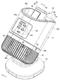
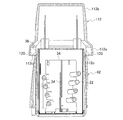
図1を参照すると、実施の形態に係る乾燥装置が全体に符号10で示されている。乾燥装置10は本体12と、本体12を支持する台座部14とを備える。
[Overall configuration]
Referring to FIG. 1, a drying apparatus according to an embodiment is generally indicated by
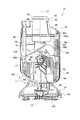
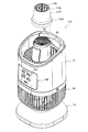
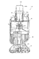
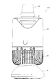
図2に示すように、乾燥装置10の本体12は、ハウジング16と、ハウジング16に収容された回転駆動されるプロペラ型のファン18及びファン18を回転駆動するための隈取モータからなる駆動源20と、ハウジング16に支持された熱源22とを備える。
As shown in FIG. 2, the
[ハウジング]
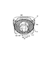
ハウジング16は風洞部24と、椀状のガード部26とを備える。風洞部24とガード部26とは、風洞部24の開放端及びガード部26の開放端が互いに突き合わされた状態で、互いに接続されている。
[housing]
The
[風洞部及びガード部]
風洞部24はファン18の回転により生じる空気流の通路を規定する円筒面24aを有し、ガード部26はガード部26内への外気の流入を許す複数の隙間26a(図1)を有する。ファン18は風洞部24内にこれと同軸に配置されている。駆動源20はガード部26内に配置され、かつガード部26に固定されている。ガード部26はその内部の駆動源20を保護するとともに、乾燥装置10を使用する者を保護する機能を有する。
[Wind tunnel and guard]
The
[ファン及び駆動源]
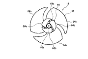
図示のファン18は、共通の軸線上に互いに間隔を置いて直列に配置された大径のファン64と、これより小径のファン66とを有するいわゆる二重ファン(図10及び図11参照)からなり、大径ファン64及び小径ファン66が、それぞれ、風洞部24を流れる空気流の移動方向における後方及び前方に位置する。二重ファンについては、後に改めて説明する。ファン18は、図示の例に代えて、大径ファン64のみからなるものとすることができる。ファン18は、その大径ファン64のハブ64aに接続された駆動源20の駆動軸20aを介して、風洞部24内に風洞部24の軸線L1(図4)の周りに回転可能に支持されている。
[Fan and drive source]
The illustrated
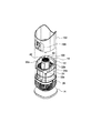
ファン18は、駆動源20の動力を受けて回転駆動されるとき、ガード部26の隙間26aからガード部26内を通して風洞部24内に外気を引き込み、風洞部24内に空気流を生じさせる。空気流は風洞部24の開放一端(入口)24bからその開放他端(出口)24cに向けて移動し、その後、出口24cを経て風洞部24の外部に放出される。図示の例では、風洞部24は、その円筒面24aに連なり、入口24bに向けて末広がりに伸びる円錐面24dを有する。したがって、入口24bは円錐面24dの開放端からなり、また出口24cは円筒面24aの開放端からなる。
When the
外部に放出された空気流は、乾燥装置10が乾燥対象とする衣類、干物、例えば壁のような物に塗られたペンキ等に当てられる。塵や埃の風洞部24内への侵入及び風洞部24外への流出を防止するため、風洞部24の入口24b及び出口24cが、それぞれ、外気及び空気流の通過を許すメッシュパネル(図示せず)で覆われているものとすることができる。ファン18は、図示の例に代えて、風洞部24外であるガード部26の内部に配置することも可能である。
The air flow released to the outside is applied to clothes, dried fish, for example, paint applied to an object such as a wall, etc., to be dried by the drying
[送出部]
図示のハウジング16は、さらに、風洞部24にその出口24cにおいて接続され風洞部24と連通する送出部32(図7〜図9参照)を備える。送出部32は、風洞部24の出口24cから放出された空気流に対して、風洞部24の軸線L1の伸長方向への送出作用を及ぼす筒状の内周面32aを有する(図3〜図6参照)。図8に示すように、送出部32はその周囲に互いに間隔をおいて配置された4つの板状の垂れ32bを有し、また、風洞部24はその周囲に互いに間隔をおいて設けられその軸線方向へ伸びる4つのリブ24eを有する。各垂れ32bと各リブ24eとは、ねじのような締結手段を介して、互いに解除可能に固定されており、これにより、送出部32が風洞部24に接続されている。
[Sending part]
The illustrated
[熱源]
熱源22は風洞部24の外部にあって風洞部24の出口24cに相対している。図示の熱源22は、通電により発熱するニクロム線からなる。ニクロム線は、互いに十字に交差するように組み合わされた耐熱性を有する2つの板片34の周囲に螺旋状に、また、空気流の移動方向に関する後方から前方に向けて直径が漸増するように巻かれている。
[Heat source]
The
[円筒]
また、熱源22及び板片34の周囲にこれらを取り巻き、また、板片34が固定された、耐熱性を有する円筒36が配置されている。円筒36は風洞部24の軸線L1の伸長方向へ伸びている。円筒36は、風洞部24の出口24cから放出される空気流の一部を受け入れ、空気流の一部の移動を許す。空気流の一部は円筒36内を移動する間に熱源22に接し、加熱された状態で円筒36の外部に放出される。
[Cylinder]
Further, a heat-
したがって、空気流は、その一部が円筒36から温風として吹き出され、他の一部が円筒36の周囲、より正確には円筒36を収容する後述の筒体42の周囲において風洞部24の出口24cから冷風として吹き出される。温風及び冷風は共に風洞部24の軸線L1の伸長方向へ流れる。温風の放出位置(円筒36の開放端)が冷風の放出位置(風洞部24の出口24c)に対し、空気流の移動方向に関する前方にあることから、温風及び冷風はこれらの移動路又は流路を規定する風洞部24及び円筒36の外部において混ざり合う。その結果、温風及び冷風が比較的均一にまた効率よく混合し、乾燥対象に到達する。温風及び冷風の混合すなわち混合風は、乾燥対象を効率よく乾燥させる。混合風の温度は、乾燥対象の濡れ具合や周囲の環境温度を考慮して定められ、混合風の所望の温度を得るために熱源22の温度が調整される。また、ファン18の回転速度すなわちその駆動源20の運転速度を変えることにより、混合風の流速を調整することができる。
Therefore, a part of the air flow is blown out from the
実施形態に係る乾燥装置10は、前記したように、適度に暖められた空気流(混合風)を発生し、これを送出するものであり、除湿された空気流の発生に必要なヒートポンプを含まない。このため、乾燥装置10を比較的重量が小さいものとし、また、乾燥装置10の形態を比較的コンパクトなものとすることができる。このことから、乾燥装置10の取扱いは比較的容易であり、また、乾燥装置10の製造に要するコストは比較的低い。
As described above, the drying
熱源22、より詳細には、円筒36の軸線が風洞部24の軸線L1の延長上、すなわち風洞部24の円形の出口24cの中央部の前方(前記空気流の移動方向に関する前方)に位置する。但し、図示の例に代えて、熱源22が配置された円筒36を出口24cの中央部以外の位置の前方に配置することが可能であるが、中央部の前方への配置は、温風及び冷風の混合度合を高めるうえで有利である。
The axis of the
円筒36の開放両端は、風洞部24におけると同様、円筒36内への塵埃の侵入及び円筒36内に塵埃が侵入した場合にこれが熱源22に接することによって生じる燃えかすの円筒36外への放出を防止するため、それぞれ、空気流の通過を許すメッシュパネル38、40(図2、図6及び図7参照)で覆われている。
At the open ends of the
図示の例にあっては、熱源22が配置された円筒36が、筒体42内に保持され、円筒36がメッシュパネル38上に着座している。
In the illustrated example, the
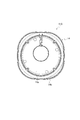
[筒体]
筒体42は、円筒部44と、該円筒部に連なる膨出部46とを備える(図5参照)。膨出部46は空気流の移動方向に関する前方に向けて先細である。
[Cylinder]
The
これによれば、風洞部24の出口24cから吹き出された冷風の一部が膨出部46に沿って流れ、冷風が、最前方の位置において、筒体42内の円筒36から吹き出る温風に衝突する。これによれば、混合度合の比較的高い温風と冷風との混合風が得られる。膨出部46は、円筒部44の周囲の一部に設ける図示の例代えて、円筒部44の周囲の全部に設けてもよい。この場合には、例えば、膨出部46が、円筒部44の周囲を取り巻き、空気流の移動方向に関する前方に向けて次第に減径する切頭円錐面を規定する。
According to this, a part of the cold air blown from the
円筒部44と膨出部46との間に存する空間には、熱源22の過熱を制御するためのバイメタル、サーモスタット等からなる制御部材47が配置されている。円筒部44と膨出部46との間に存する空間を制御部材47の配置空間として利用することにより、乾燥装置10自体のコンパクト化を図ることができる。符号49は、膨出部46に形成された、制御部材47の出し入れを行うための開口(図示せず)を閉じる蓋を示す。
A
[保持筒]
ハウジング16を構成する送出部32は、その中央部を貫通する、保持筒48を有する(図7〜図9参照)。保持筒48は、筒体42の円筒部44の一部を受け入れる円筒空間48Aと、膨出部46の一部を受け入れる隙間48Bとを有する。保持筒48は、複数の細長い支持骨51を介して、送出部32の中央に支持されている。複数の支持骨51は一の仮想平面上に互いに間隔を置いて配置され、それぞれ、送出部32の内周面32a(図1)から保持筒48へと円弧状に湾曲して伸びている。また、保持筒48は、風洞部24内を伸びる一端部48aと、筒体42の側へ突出する他端部48bとを有する。支持骨51は図示の例に代えて直線的に伸びあるいは他の湾曲形態をもって伸びるものとすることができる。冷風は支持骨51相互間を経て流動する。
[Holding cylinder]
The
筒体42には、メッシュパネル38で覆われた開放端からその軸線方向へ伸びる2つのピン50(図7)が形成されている。他方、保持筒48にはその軸線方向伸びる2つの案内溝52(図9)が形成されている。各案内溝52は、各ピン50の挿入を許す開放一端52aと、挿入された各ピン50を止める他端52bとを有する。両ピン50がそれぞれ両案内溝52にその開放一端52aから挿入され、その他端52bで止められるとき、筒体42の円筒部44の一部と膨出部46の一部とが保持筒48の円筒空間48Aと隙間48Bとにそれぞれ受け入られる。このとき、筒体42のメッシュパネル38が、風洞部24の出口24cを含む仮想面上に位置する(図2参照)。
The
[リード線を保持する溝]
好ましくは、保持筒48の複数の支持骨51の内の1つ以上(図示の例にあっては2つ)の支持骨51A(図9)に、支持骨51Aの伸長方向へ伸びかつ風洞部24に向けて開放する溝54が設けられる。溝54は、熱源22に電力を供給するためのリード線(図示せず)の配置空間として利用することができる。これによれば、リード線を、これが支持骨51相互間を横切るように配置すること、および、これに伴ってリード線が空気流に対する流動抵抗となることを回避することができる。また、支持骨51Aを図示の例におけるように湾曲して伸びるものとすることにより、これらを直線的に伸びるものとする場合よりも、リード線が溝54内から脱落しにくいものとすることができる。
[Groove for holding lead wire]
Preferably, one or more (two in the illustrated example) of the plurality of
[風洞部及びガード部の相互接続]
図8に示すように、ファン18が配置された風洞部24とファン18の駆動源20が配置されたガード部26とは、これらを二つの異なる接続手段をもって相互に接続することができる。これによれば、一方の接続手段に不具合が生じた場合にあっても、他方の接続手段をもって風洞部24及びガード部26相互の接続状態を維持することができ、これにより、乾燥装置10の配置位置の変更のための移動や、乾燥装置10に対する使用者の偶発的な接触、衝突等を原因とする風洞部24及びガード部26相互の予期しない分離及びこれに伴うファン18やファン18と駆動源20との接続構造の破損を防止することができる。
[Interconnection of wind tunnel and guard]
As shown in FIG. 8, the
一方の接続手段は、弾性変形可能である複数の爪部材56からなる。これらの爪部材56は、風洞部24の周りに互いに間隔をおいて配置され、風洞部24からガード部26に向けて伸びている。各爪部材56は、風洞部24がガード部26に部分的に嵌合した状態でガード部26上に載置されるとき、弾性変形をしてガード部26内をその隙間26aに向けて移動し、隙間26aに到達すると同時に弾性復帰し、ガード部26、より詳細にはガード部26の開放端を規定する帯状部26bに係止し、これにより、風洞部24とガード部26とが接続状態におかれる(図1参照)。
One connection means includes a plurality of
また、他方の接続手段は、風洞部24にその周囲に間隔をおいて設けられた、ガード部26に向けて開放する複数(図示の例では3つ)の半長円形の穴58と、ガード部26にその周囲に間隔をおいて設けられた、穴58と同数の複数の円形の孔60と、孔60と同数のボタン形の係止部材62とからなる。この接続手段にあっては、風洞部24がガード部26に部分的に嵌合した状態でガード部26上に載置されるとき、各穴58と各孔60とが互いに整合する。次いで、各孔60から各穴58に係止部材62を通し、係止部材62を図示の例では90度回転させると、係止部材62が風洞部24の内周面に係止する。より詳細には、係止部材62の先端部に設けられた係止爪62aが弾性変形し、風洞部24の内周面に強固に接する。その結果、風洞部24とガード部26とが相互に固定され、また、これにより相互に接続される。
The other connecting means includes a plurality of (three in the illustrated example)
これらの2つの接続手段による風洞部24とガード部26との相互接続及びその解除は比較的容易に行うことができる。このため、乾燥装置10のメインテナンスを行う際の風洞部24及びガード部26の分離及び再接続を比較的容易に行うことができる。なお、前記一方の接続手段における爪部材56と、前記他方の接続手段における穴58及び孔60とは、風洞部24及びガード部26の周方向に関して、互いに異なる位置に配置されている。
Interconnection between the
[ファンの構造]
風洞部24内に配置されるファン18に関して、好ましくは、図2に示すように、その大径ファン64のハブ64aの位置が、熱源22が収容された筒体42の円筒部44の近傍にあり、また、大径ファン64のハブ64aの外径が、筒体42の円筒部44の内径又は熱源22を取り巻く円筒36の内径にほぼ等しい。これによれば、大径ファン64のハブ64aが空気流の一部が円筒36内に流入することを妨害する。このため、円筒36内への空気流の一部の流入量を制限することができ、これにより、円筒36を経てその外部に流出する温風の速度を、風洞部24の出口24cを経て流出する冷風の速度よりも小さいものに設定することができる。例えば、温風の流出速度及び冷風の流出速度をそれぞれ、例えば約2m/秒及び約5m/秒に設定することができる。このように設定することにより、温風と冷風との混合度合をより一層高めることができ、また、混合風をより遠方に送ることができる。
[Fan structure]
With respect to the
好ましくは、小径ファン66の外径が大径ファン64のハブ64aの外径にほぼ等しい。さらに好ましくは、小径ファン66の一部が保持筒48の一端部48a内に位置する。(図2及び図11参照)。これによれば、大径ファン64により発生される空気流とは別の流量及び流速の異なる空気流を生じさせ、これを円筒36内に送り込むことができる。なお、図示の例では、大径ファン64及び小径ファン66がそれぞれ3つの羽根64b及び3つの羽根66bを有するが、羽根64b及び羽根64bの枚数は図示の例とは異なるものに設定することができる。また、図示の例では、3つの羽根64b及び3つの羽根66bが、これらのハブ64a及びハブ66aの共通軸線の周りに同位相に配置されている。これに代えて、図12に示すように、3つの羽根64b及び3つの羽根66bが共通軸線の周りに任意の、例えば30度の位相差が存するように配置することができる。
Preferably, the outer diameter of the small-
図11に示すように、大径ファン64と小径ファン66とは、次のような態様で相互に接続することができる。
As shown in FIG. 11, the large-
大径ファン64のハブ64aは、共通軸線に関して互いに反対方向へ開放する2つの凹所68、70と、両凹所68、70内を共通軸線上において互いに反対方向へ伸びる2つの突起72、74とを備える。両突起72、74がそれぞれ両凹所68,70内を伸びていることから、ハブ64aからの両突起72、74の突出量を比較的小さいものとし、これにより大径ファン64自体の共通軸線方向の長さを比較的小さいものに抑えることができる。他方、小径ファン66のハブ66aは、共通軸線上を大径ファン64の凹所70に向けて伸びる孔76を有する突起78を備える。
The
大径ファン64の一方の突起72は、駆動源20の駆動軸20aを受け入れる孔80を有する。突起72の孔80及びこれに受け入れられる駆動軸20aは、突起72及び駆動軸20aの一体的な回転が可能であるように、孔80及び駆動軸20aは共通のD形の横断面形状を有する。また、大径ファン64の他方の突起74は、小径ファン66の突起78の孔76に圧入されており、これにより、大径ファン64と小径ファン66とが一体をなすように強固に接続されている。したがって、大径ファン64と小径ファン66とを相互に接続するための特別な接続部材を必要としない。また、大径ファン64と小径ファン66との相互接続を比較的容易に行うことができる。さらに、ファン18の製造に要するコストを比較的低廉のものとすることができる。
One
[本体の揺動及び回転]
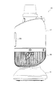
乾燥装置10は、好ましくは、本体12が、台座部14に対して、風洞部24の軸線L1に直交する軸線L2(図4)の周りに矢印aの方向へ揺動可能であり、また、台座部14の軸線L3(図4)の周りに回転可能である。これによれば、本体12の揺動位置すなわち仰角及び回転位置をそれぞれ変更することが可能であり、これにより、放出される前記混合風の向きを変更することができる。
[Oscillation and rotation of the body]
The drying
本体12の揺動範囲、すなわち軸線L2の周りに揺動する角度の範囲は、好ましくは、本体12が水平状態(図示せず)となる角度(0度)から本体12が鉛直状態(図3及び図4)となる角度(90度)までの範囲に設定される。なお、図1は、本体12が前記水平状態又は鉛直状態から軸線L2の周りに45度の角度だけ揺動された状態を示す。また、本体12が台座部14の軸線L3の周りに回転する角度の範囲、いわゆる首振り角度の範囲は、好ましくは、0度〜90度の範囲に設定される。
The swinging range of the
[本体と台座]
本体12を軸線L2の周りに揺動可能とし、また、軸線L3の回りに回転可能とするために、図13に示すように、本体12が一対の板状の脚部材82を介して台座部14上に支持されている。また、台座部14が、円板状の静止部分14aと、該静止部分にその周方向へ回転可能に接続された可動部分14bとで構成されている(図2、図3、図7参照)。
[Main body and pedestal]
In order to make the
両脚部材82は、それぞれ、台座部14の可動部分14bから、ガード部26に設けられガード部26の側面から底面に向けて伸びる2つの細長い開口84を経てガード部26内に伸び、ガード部26内において駆動源20に固定されている。
The both
また、図4に示すように、ガード部26内に、軸線L2の周りに回転可能に支持された、互いに相対する2つの円板状部材86と、各円板状部材86にその径方向へ移動可能に取り付けられた、球面状の頭部を有するピン部材88と、ピン部材88に対してその軸線方向へばね力を及ぼす被圧縮のコイルばね90とが配置されている。
Further, as shown in FIG. 4, two disk-shaped
さらに、円弧状部材92が、ガード部26内において、各円板状部材86の周面から間隔をおいて同心的に配置されかつ各両脚部材82の先端部に固定されている。円弧状部材92は、円板状部材86に向けて開放する、周方向に間欠的に配置された複数の半球状の窪み94を有する。さらに、ガード部26の底面の一部26cと、これに相対する台座部14の可動部分14bの頂面の一部96とが、それぞれ、同曲率の2つの円弧面を規定する。
Further, the arc-shaped
これによれば、手動により本体12を円板状部材86と共に軸線L2の周りに揺動させることができる。このとき、各円板状部材86が円弧状部材92に対して相対的に回転し、コイルばね90からのばね力を受けているピン部材88の頭部が円弧状部材92の一の窪み94内からこれに隣接する他の窪み94内へと移動する。このとき、移動後の位置が維持される。本体12が揺動されるとき、両脚部材82はそれぞれガード部26の両開口84内を該開口の伸長方向へ相対的に移動する。また、ガード部26の底面の一部26cが、相対する台座部14の可動部分14bの頂面の一部96に沿って矢印aの方向へ移動する。
According to this, the
台座部26は、その可動部分14bに回転動力を与える電動モータからなる駆動源98(図2参照)を備える。駆動源98は静止部分14aに支持され、その駆動軸100が可動部分14bに接続されている。本体12は、駆動源98を作動させることにより、台座部14の可動部分14bと共に、台座部26の軸線L3の回りに回転する。
The
[カバー]
本体12は、好ましくは、その風洞部24を、より好ましくは送出部32をも保護する筒状のカバー102を備える。カバー102はその内部にハウジング16の送出部32及び風洞部24を順次に通すことにより、風洞部24及び送出部32の周囲を、風洞部24及び送出部32との間に空隙H(図4)をおいて取り囲むように配置することができる。カバー102はガード部26に固定することができる。
[cover]
The
カバー102は、該カバーと風洞部24及び送出部32との間に空隙Hが存することから、これが外力を受けるとき、弾性変形又は塑性変形をして、風洞部24又は送出部32に対して外力が及ばないようにこれらを保護する。これにより、風洞部24が規定する空気流の通路又は送出部32が規定する空気流の送出路の形状が変化することを防止する。
Since there is a gap H between the
[操作盤]
カバー102には、その表面に、乾燥装置10の作動、風量、風速等の切り替え、タイマーの設定等の操作を行うための複数の操作ボタン104が設けられた操作盤106が取り付けられている(図1)。操作ボタン104は、前記表面の一部に形成された平坦面102a(図4)上に配置されている。また、操作盤106は、好ましくは、本体12が前記水平状態と前記垂直状態との間で軸線L2の周りに揺動されるときに操作盤106が上方を向く位置に取り付けられる。このため、操作盤106を乾燥装置10の使用者が目視可能の範囲及び操作しやすい状態におくことができる。
[Operation board]
On the surface of the
また、操作盤106が、外気の吸い込み作用を及ぼすガード部26の上方位置にある風洞部24の周囲に配置されている。このため、使用者が操作盤106に触れるとき、使用者の毛髪や衣類の一部がガード部26の隙間26aを通してガード部26内に引き込まれる危険性を低減することできる。
Further, the
さらに、操作盤106の操作ボタン104に接続された操作部材107(図4)がカバー102と風洞部24との間の空隙H内に収容されている。これは、乾燥装置10のコンパクト化に寄与する。
Further, an operation member 107 (FIG. 4) connected to the
[取手]
図3、図6及び図8に示すように、乾燥装置10は、好ましくは、これを持ち運びするための把持可能の取手108を有する。取手108はハウジング16を構成する送出部32に設けられ、送出部32の一部を成す。取手108は、好ましくは、操作盤106が設けられたカバー102の表面と相対するカバー102の裏面の側に設けられる。取手108は送出部32の一部を構成することから、取手108によって温風及び冷風の流れが遮られない。また、温風及び冷風の放出口の近傍に位置することから、乾燥装置10の本体12が垂直状態(図3及び図4に示す状態)にあっても、取手108を掴んで乾燥装置10をそのままの状態で移動させることができる。
[Toride]
As shown in FIGS. 3, 6 and 8, the drying
次に、図14〜図24を参照すると、他の実施の形態に係る乾燥装置が全体に符号110で示されている。なお、図18〜図22には、操作ボタン104の図示を省略した操作盤106が示されている。操作盤106には、操作ボタン104に代わる他の操作手段を配置することが可能である。
Next, referring to FIGS. 14 to 24, a drying apparatus according to another embodiment is generally indicated by
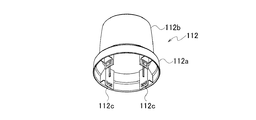
図14〜図24に示す乾燥装置110は、構成上、次の(1)〜(4)に記載の事項についてのみ、図1〜図13に示す乾燥装置10と相違する。(1)乾燥装置110は、熱源22の円筒36に被せられたキャップ112を有する。乾燥装置10はキャップ112を有しない。(2)乾燥装置110は、乾燥装置10が有する、風洞部24内を伸びる一端部48aを有しない(図15)。(3)乾燥装置110は、制御部材47に接するアルミニウム板114(図15)を有する。乾燥装置10はアルミニウム板114を有しない。(4)乾燥装置110は傾斜スイッチ116(図15)を有する。乾燥装置10は傾斜スイッチ116を有しない。
The drying
[キャップ]
熱源22を取り巻く円筒36に被せられたキャップ112は、熱源22により高温状態におかれる円筒36及び筒体42への人体の一部の接触とこれに伴う火傷の発生を防止するために設けられている。キャップ112は、内面及び外面が円形の横断面形状を呈する全体に先細の筒状体からなる。キャップ112は、円筒36の内径及び筒体42の外径より大きい内径を有する開放基部112aと、先細の開放先端部112bと、開放基部112aの内部にその周方向に互いに間隔をおいて設けられた4つの着座部112cとを有する(図16)。開放先端部112bは前記温風の通過を許すガード118(図14)で覆われている。
[cap]
The
キャップ112は4つの着座部112cを介して筒体42上に載置されており、キャップ112の開放基部112aと円筒36及び筒体42との間に隙間120(図17)が存する。この隙間120を通して、風洞部24内から放出される前記冷風がキャップ112内に導かれ、キャップ112内を経て、開放先端部112bから外部に放出される。前記冷風は、キャップ112内において前記温風と混合すると共に、キャップ112に冷却作用を及ぼす。これにより、キャップ112の過熱が防止される。
The
[アルミニウム板]
図15に示す例にあっては、制御部材47を構成するサーモスタットに取り付けられ熱源22に面するアルミニウム板114を介して、熱源22が発する熱が前記サーモスタットに伝えられる。これによれば、アルミニウム板114を有しない乾燥装置10と比べて、前記サーモスタットによる熱の検知をより良好にすることができる。
[Aluminum plate]
In the example shown in FIG. 15, the heat generated by the
[傾斜スイッチ]
傾斜スイッチ116は台座部14内に配置されており、乾燥装置110が例えば地震の発生に伴って予め定められた角度で傾斜するとき、熱源22に対する電力の供給が停止される。これにより、乾燥装置110の転倒に伴う火災の発生が防止される。
[Tilt switch]
The
[その他の実施の形態]
上記のように、実施の形態によって記載したが、この開示の一部をなす論述および図面は例示的なものであり、これに限定するものであると理解すべきではない。この開示から当業者には様々な代替実施の形態、実施例および運用技術が明らかとなろう。
[Other embodiments]
As described above, the embodiments have been described. However, it should be understood that the descriptions and drawings forming a part of this disclosure are illustrative and are not restrictive. From this disclosure, various alternative embodiments, examples and operational techniques will be apparent to those skilled in the art.
このように、本実施の形態はここでは記載していない様々な実施の形態などを含む。 As described above, this embodiment includes various embodiments not described here.
本実施の形態の乾燥装置は、衣類、干物、ペンキ等の乾燥装置のみならず、様々な乾燥用途に適用可能である。 The drying device of this embodiment can be applied not only to drying devices such as clothes, dried fish, and paint, but also to various drying applications.
10…乾燥装置
12…本体
14…台座部
14a…台座部の静止部分
14b…台座部の可動部分
16…ハウジング
18…ファン
20…ファンの駆動源
22…熱源
24…風洞部
26…ガード部
32…送出部
36…円筒
42…筒体
44…筒体の円筒部
46…筒体の膨出部
48…支持筒
51…支持骨
56…爪部材
62…係止部材
64…小径ファン
66…大径ファン
102…カバー
106…操作盤
108…取手
110…乾燥装置
112…キャップ
DESCRIPTION OF
Claims (10)
前記本体を支持する台座部と
を備え、
前記本体は、ハウジングと、前記ハウジングの内部に収容された回転駆動されるファン及び前記ファンの駆動源と、前記ハウジングに支持された熱源と、前記ハウジングに支持され前記熱源を保持する筒体とを備え、
前記ハウジングは、前記ファンの回転により生じる空気流の通路を規定する風洞部を備え、
前記風洞部はその外部に前記空気流を放出する出口を有し、
前記熱源は、前記風洞部に対して前記空気流の移動方向の下流側に位置すると共に、前記風洞部の出口に相対し、
前記筒体は、円筒部と、前記円筒部の周りを前記円筒部との間に間隔をおいて部分的に取り巻く膨出部とを有し、前記円筒部と前記膨出部との間隔は前記空気流の移動方向の下流側に向けて漸減していることを特徴とする乾燥装置。 The body,
A pedestal that supports the body,
The main body includes a housing, a rotationally driven fan housed in the housing, a drive source of the fan, a heat source supported by the housing, and a cylindrical body supported by the housing and holding the heat source. With
The housing includes a wind tunnel portion that defines a passage for airflow generated by rotation of the fan,
The wind tunnel portion has an outlet for discharging the air flow to the outside thereof,
The heat source is located on the downstream side in the moving direction of the air flow with respect to the wind tunnel portion, and is opposed to the outlet of the wind tunnel portion,
The cylindrical body has a cylindrical portion and a bulging portion that partially surrounds the cylindrical portion with a space between the cylindrical portion, and the interval between the cylindrical portion and the bulging portion is The drying apparatus, wherein the drying apparatus gradually decreases toward the downstream side in the moving direction of the air flow .
前記制御部材は、前記筒体の円筒部と膨出部との間に配置されていることを特徴とする請求項1に記載の乾燥装置。 The main body includes a control member for controlling overheating of the heat source,
The drying apparatus according to claim 1 , wherein the control member is disposed between a cylindrical portion and a bulging portion of the cylindrical body .
前記ハウジングは前記可動部分に取り付けられていることを特徴とする請求項1に記載の乾燥装置。 The pedestal portion includes a disc-shaped stationary part, and a movable part connected to the stationary part so as to be rotatable in the circumferential direction thereof,
The drying apparatus according to claim 1 , wherein the housing is attached to the movable part .
前記駆動源は前記台座部の静止部分に支持されていることを特徴とする請求項5に記載の乾燥装置。 The pedestal portion includes a drive source that gives rotational power to the movable part,
The drying apparatus according to claim 5 , wherein the driving source is supported by a stationary portion of the pedestal portion .
前記本体を支持する台座部と
を備え、
前記本体は、ハウジングと、前記ハウジングの内部に収容された回転駆動されるファン及び前記ファンの駆動源と、前記ハウジングに支持された熱源と、前記ハウジングに支持され前記熱源を保持する筒体とを備え、
前記ハウジングは、前記ファンの回転により生じる空気流の通路を規定する風洞部を備え、
前記風洞部はその外部に前記空気流を放出する出口を有し、
前記熱源は、前記風洞部に対して前記空気流の移動方向の下流側に位置すると共に、前記風洞部の出口に相対し、
前記ファンは、その回転軸が前記風洞部の軸線と同軸となるように前記風洞部の内部に配置され、
前記ファンは、前記空気流の移動方向に互いに間隔を置いて直列に配置された大径ファンと小径ファンとを有する二重ファンから成ることを特徴とする乾燥装置。 The body,
A pedestal for supporting the body;
With
The main body includes a housing, a rotationally driven fan housed in the housing, a drive source of the fan, a heat source supported by the housing, and a cylindrical body supported by the housing and holding the heat source. With
The housing includes a wind tunnel portion that defines a passage for airflow generated by rotation of the fan,
The wind tunnel portion has an outlet for discharging the air flow to the outside thereof,
The heat source is located on the downstream side in the moving direction of the air flow with respect to the wind tunnel portion, and is opposed to the outlet of the wind tunnel portion,
The fan is arranged inside the wind tunnel portion so that the rotation axis thereof is coaxial with the axis of the wind tunnel portion,
The fan Drying device you characterized in that it consists of a double fan with a large diameter fan and a small diameter fan disposed in series at a distance from one another in the moving direction of the air flow.
前記本体を支持する台座部と
を備え、
前記本体は、ハウジングと、前記ハウジングの内部に収容された回転駆動されるファン及び前記ファンの駆動源と、前記ハウジングに支持された熱源と、前記ハウジングに支持され前記熱源を保持する筒体とを備え、
前記ハウジングは、前記ファンの回転により生じる空気流の通路を規定する風洞部を備え、
前記風洞部はその外部に前記空気流を放出する出口を有し、
前記熱源は、前記風洞部に対して前記空気流の移動方向の下流側に位置すると共に、前記風洞部の出口に相対し、
前記ハウジングは、前記風洞部の出口に接続される送出部を備え、
前記送出部は、前記風洞部の出口から放出された空気流に対して前記風洞部の軸線の伸長方向への送出作用を及ぼす筒状の内周面を有し、該内周面から円弧状に湾曲して伸びる複数の支持骨を有していることを特徴とする乾燥装置。 The body,
A pedestal for supporting the body;
With
The main body includes a housing, a rotationally driven fan housed in the housing, a drive source of the fan, a heat source supported by the housing, and a cylindrical body supported by the housing and holding the heat source. With
The housing includes a wind tunnel portion that defines a passage for airflow generated by rotation of the fan,
The wind tunnel portion has an outlet for discharging the air flow to the outside thereof,
The heat source is located on the downstream side in the moving direction of the air flow with respect to the wind tunnel portion, and is opposed to the outlet of the wind tunnel portion,
The housing includes a delivery part connected to an outlet of the wind tunnel part,
The delivery section has a cylindrical inner peripheral surface that exerts a delivery action in the direction of extension of the axis of the wind tunnel section with respect to the air flow discharged from the outlet of the wind tunnel section, and has an arc shape from the inner peripheral surface. drying device characterized by having a plurality of supporting bone extending curved.
Priority Applications (1)
| Application Number | Priority Date | Filing Date | Title |
|---|---|---|---|
| JP2015161555A JP6603511B2 (en) | 2015-08-19 | 2015-08-19 | Drying equipment |
Applications Claiming Priority (1)
| Application Number | Priority Date | Filing Date | Title |
|---|---|---|---|
| JP2015161555A JP6603511B2 (en) | 2015-08-19 | 2015-08-19 | Drying equipment |
Publications (2)
| Publication Number | Publication Date |
|---|---|
| JP2017038753A JP2017038753A (en) | 2017-02-23 |
| JP6603511B2 true JP6603511B2 (en) | 2019-11-06 |
Family
ID=58206011
Family Applications (1)
| Application Number | Title | Priority Date | Filing Date |
|---|---|---|---|
| JP2015161555A Active JP6603511B2 (en) | 2015-08-19 | 2015-08-19 | Drying equipment |
Country Status (1)
| Country | Link |
|---|---|
| JP (1) | JP6603511B2 (en) |
Families Citing this family (2)
| Publication number | Priority date | Publication date | Assignee | Title |
|---|---|---|---|---|
| JP6363811B1 (en) * | 2017-09-29 | 2018-07-25 | アイリスオーヤマ株式会社 | Circulator |
| CN114111277B (en) * | 2021-11-16 | 2023-04-28 | 安徽省福宁米业有限公司 | Granule dewatering equipment for fruit and vegetable rice preparation |
Family Cites Families (5)
| Publication number | Priority date | Publication date | Assignee | Title |
|---|---|---|---|---|
| JPS622908U (en) * | 1985-06-24 | 1987-01-09 | ||
| JPH06281256A (en) * | 1993-03-26 | 1994-10-07 | Fujikura Ltd | Warm air generating device |
| EP1000570A1 (en) * | 1998-11-12 | 2000-05-17 | MO-EL S.r.l. | A heating device |
| JP2000201723A (en) * | 1999-01-11 | 2000-07-25 | Hirokatsu Nakano | Hair dryer with improved hair setting effect |
| JP4131169B2 (en) * | 2002-12-27 | 2008-08-13 | 松下電工株式会社 | Hair dryer |
-
2015
- 2015-08-19 JP JP2015161555A patent/JP6603511B2/en active Active
Also Published As
| Publication number | Publication date |
|---|---|
| JP2017038753A (en) | 2017-02-23 |
Similar Documents
| Publication | Publication Date | Title |
|---|---|---|
| US6094837A (en) | Multi-functional hand-held hair dryer | |
| JP5702443B2 (en) | Fan assembly | |
| EP3649885B1 (en) | Wind velocity changing device and hair dryer | |
| JP2012501714A (en) | Hair dryer, accessories for hair dryers, and hair dryers with such accessories | |
| US20200085252A1 (en) | Dryer | |
| US20050123392A1 (en) | Multi-directional tower fan | |
| HK1215523A1 (en) | Nozzle for hair dryer | |
| EP3626107B1 (en) | Dryer | |
| KR101905697B1 (en) | Neck band type fan | |
| JP6603511B2 (en) | Drying equipment | |
| CN113384057B (en) | Adjusting part and hair-dryer | |
| KR200483235Y1 (en) | Neck pan | |
| EP3273062A1 (en) | Blower | |
| JP6838006B2 (en) | Hair care device | |
| JP2017108786A (en) | Hair Dryer | |
| KR101477739B1 (en) | Hair dryer | |
| CN115500596A (en) | hair care appliance | |
| KR20200116277A (en) | hair dryer | |
| KR20170054771A (en) | Hair dryer | |
| JP2019126412A (en) | Hair dryer blowing nozzle and hair dryer | |
| KR102223291B1 (en) | Portable fan | |
| JP5495253B2 (en) | Hair dryer | |
| CN107278129B (en) | Wind vibrating device and hair drier comprising same | |
| JP6440788B1 (en) | Drying equipment | |
| CN107781932B (en) | Dryer and control method of dryer |
Legal Events
| Date | Code | Title | Description |
|---|---|---|---|
| A621 | Written request for application examination |
Free format text: JAPANESE INTERMEDIATE CODE: A621 Effective date: 20180502 |
|
| A977 | Report on retrieval |
Free format text: JAPANESE INTERMEDIATE CODE: A971007 Effective date: 20190213 |
|
| A131 | Notification of reasons for refusal |
Free format text: JAPANESE INTERMEDIATE CODE: A131 Effective date: 20190326 |
|
| A521 | Written amendment |
Free format text: JAPANESE INTERMEDIATE CODE: A523 Effective date: 20190524 |
|
| TRDD | Decision of grant or rejection written | ||
| A01 | Written decision to grant a patent or to grant a registration (utility model) |
Free format text: JAPANESE INTERMEDIATE CODE: A01 Effective date: 20191001 |
|
| A61 | First payment of annual fees (during grant procedure) |
Free format text: JAPANESE INTERMEDIATE CODE: A61 Effective date: 20191011 |
|
| R150 | Certificate of patent or registration of utility model |
Ref document number: 6603511 Country of ref document: JP Free format text: JAPANESE INTERMEDIATE CODE: R150 |