JP6601751B2 - Mailbox - Google Patents

Mailbox Download PDF

Info

Publication number
JP6601751B2
JP6601751B2 JP2015003970A JP2015003970A JP6601751B2 JP 6601751 B2 JP6601751 B2 JP 6601751B2 JP 2015003970 A JP2015003970 A JP 2015003970A JP 2015003970 A JP2015003970 A JP 2015003970A JP 6601751 B2 JP6601751 B2 JP 6601751B2
Authority
JP
Japan
Prior art keywords
flap
mouth frame
front opening
mailbox
opening
Prior art date
Legal status (The legal status is an assumption and is not a legal conclusion. Google has not performed a legal analysis and makes no representation as to the accuracy of the status listed.)
Expired - Fee Related
Application number
JP2015003970A
Other languages
Japanese (ja)
Other versions
JP2016129539A (en
Inventor
光久 藤野
Current Assignee (The listed assignees may be inaccurate. Google has not performed a legal analysis and makes no representation or warranty as to the accuracy of the list.)
Panasonic Intellectual Property Management Co Ltd
Original Assignee
Panasonic Intellectual Property Management Co Ltd
Priority date (The priority date is an assumption and is not a legal conclusion. Google has not performed a legal analysis and makes no representation as to the accuracy of the date listed.)
Filing date
Publication date
Application filed by Panasonic Intellectual Property Management Co Ltd filed Critical Panasonic Intellectual Property Management Co Ltd
Priority to JP2015003970A priority Critical patent/JP6601751B2/en
Publication of JP2016129539A publication Critical patent/JP2016129539A/en
Application granted granted Critical
Publication of JP6601751B2 publication Critical patent/JP6601751B2/en
Expired - Fee Related legal-status Critical Current
Anticipated expiration legal-status Critical

Links

Images

Description

本発明は、郵便受けに関する。   The present invention relates to a mailbox.

従来、前面に前開口が設けられた箱状の郵便受け本体と、前開口の周囲に設けられた口枠部と、左右方向を軸方向とする回転軸周りを回転するフラップと、を備えた郵便受けが知られている(例えば特許文献1参照)。   2. Description of the Related Art Conventionally, a postbox provided with a box-shaped postbox body having a front opening on the front surface, a mouth frame provided around the front opening, and a flap that rotates about a rotation axis about the left-right direction. Is known (see, for example, Patent Document 1).

フラップは、その上端部に回転中心を有し、後方から前開口を閉塞し且つ、後斜め上方に回転することで前開口を開放する。   The flap has a rotation center at its upper end, closes the front opening from the rear, and opens the front opening by rotating rearward and obliquely upward.

特開2011−152468号公報JP 2011-152468 A

特許文献1に記載されているフラップは、前開口を閉塞した際、前開口に挿入される側面視矩形状の突出部を有する。   When the front opening is closed, the flap described in Patent Document 1 has a rectangular protrusion in a side view inserted into the front opening.

この郵便受けでは、ユーザーが、投函物を口枠部の前端の投入口を通して前開口から郵便受け本体内に投函する際、投函物が突出部に当たることにより、フラップが後斜め上方向に回転する機構となっている。   In this mailbox, when a user throws a thrown object into the main body of the mailbox from the front opening through the insertion slot at the front end of the mouth frame, the flap rotates backward and obliquely upward when the thrown object hits the protrusion. It has become.

しかし、投函物が厚みのある(例えば前開口の上下方向の寸法と同じ位の厚み)ものであると、投函物によりフラップを回転させる際、突出部の上角部に投函物が引っ掛かり易いため、投函物の郵便受け本体内への投函が妨げられる虞があった。   However, if the throwing object is thick (for example, the same thickness as the vertical dimension of the front opening), the throwing object is easily caught on the upper corner of the protrusion when the flap is rotated by the throwing object. There was a risk that the posting of the post into the mailbox body would be hindered.

本発明は上記従来の問題点に鑑みて発明したものであって、その目的とするところは、投函物を投函し易い、郵便受けを提供することを課題とするものである。   The present invention has been invented in view of the above-mentioned conventional problems, and an object of the present invention is to provide a mailbox that is easy to post a post.

上記課題を解決するために、本発明は、以下のような構成とする。   In order to solve the above problems, the present invention has the following configuration.

箱状であり前面に前開口が設けられた郵便受け本体と、前記前開口の周囲から前方に突出し、前端に前記前開口に通じる投入口を有する口枠部と、左右方向を軸方向とする回転軸の周りを回転し、前記郵便受け本体の内側に配置されるフラップと、を備え、前記フラップは、その上端部に回転中心を有し、前記前開口に後方から近付いて閉塞し且つ、後側に回転することで前記前開口を開放するものであり、前記フラップは、前記前開口を閉塞したとき前記前開口に挿入される突出部を有し、前記突出部の前面は、下側に行く程前側に位置するように傾斜する傾斜面となり、前記口枠部は、内側の下部に左右方向の全長に亘って設けられる縦面部を有し、前記口枠部の内側には、その上部で且つ前記縦面部よりも前方に配置され、前記縦面部に向かって発光する照明部が設けられ、前記照明部は、前記口枠部における左右方向と平行に配置される導光棒と、前記導光棒の左右方向の端面から光を入射させる光源と、を備え、前記導光棒における前記縦面部に向く面が出射面であることを特徴とする。
A box-shaped postbox main body with a front opening provided on the front surface, a front frame protruding from the periphery of the front opening and having an insertion port leading to the front opening at the front end, and rotation about the left-right direction as an axial direction A flap that rotates about an axis and is disposed inside the mailbox body, the flap having a center of rotation at an upper end portion thereof, approaching the front opening from the rear and closing, and a rear side The flap has a protrusion that is inserted into the front opening when the front opening is closed, and the front surface of the protrusion goes downward. Ri Do an inclined surface inclined so as to be positioned on the front side extent, the opening frame portion has a vertical surface portion is provided over the entire length of the lateral direction in the lower part of the inner, inside the opening frame section, the The upper surface portion is disposed in front of the vertical surface portion, and the vertical surface portion An illuminating unit that emits light toward the light source, the illuminating unit includes a light guide bar arranged in parallel with the left-right direction of the mouth frame part, and a light source that makes light incident from an end surface in the left-right direction of the light guide bar, comprises a surface facing said longitudinal face of said light guide rod and said exit surface der Rukoto.

本発明の郵便受けでは、フラップに傾斜面が設けられることで、厚みのある投函物を投入しても、投函物に突出部が引っ掛かり難くなり、ユーザーが投函物を投函し易い。   In the mailbox according to the present invention, the inclined surface is provided on the flap, so that even if a thick throwing object is inserted, the protruding portion is not easily caught on the throwing object, and the user can easily throw the throwing object.

図1は、本実施形態の郵便受けの斜視図である。FIG. 1 is a perspective view of a mailbox according to the present embodiment. 図2は、本実施形態の郵便受けの縦断面図である。FIG. 2 is a longitudinal sectional view of the mailbox according to this embodiment. 図3は、本実施形態のフラップの斜視図である。FIG. 3 is a perspective view of the flap of the present embodiment. 図4は、本実施形態の郵便受けの照明部が設けられた部分の縦断面図である。FIG. 4 is a vertical cross-sectional view of a portion provided with the illumination portion of the mailbox according to the present embodiment.

以下、本発明を添付図面に示す実施形態に基いて説明する。   Hereinafter, the present invention will be described based on embodiments shown in the accompanying drawings.

本実施形態の郵便受け1は、住宅家屋の外構用の門柱に埋め込まれるようにして取り付けられる。本実施形態の外構には、オープン外構、クローズ外構やセミクローズ外溝が用いられる。   The mailbox 1 of the present embodiment is attached so as to be embedded in a gate pillar for an exterior of a residential house. For the exterior of this embodiment, an open exterior, a closed exterior, or a semi-closed exterior groove is used.

郵便受け1は、図1に示すように、箱状の郵便受け本体2を備える。郵便受け本体2は、天面部22、一対の側面部23、底面部24、正面部21及び背面部25を有する略六面体状に形成される。郵便受け本体2は、本実施形態では、直方体状に形成されるが、立方体状でもよい。   As illustrated in FIG. 1, the mailbox 1 includes a box-like mailbox body 2. The postbox main body 2 is formed in a substantially hexahedron shape having a top surface portion 22, a pair of side surface portions 23, a bottom surface portion 24, a front surface portion 21, and a back surface portion 25. In the present embodiment, the mailbox main body 2 is formed in a rectangular parallelepiped shape, but may be in a cubic shape.

ここで、本実施形態において、背面部25から正面部21に向かう方向を前方向、その反対方向を後方向、前後方向とは直角な水平方向を左右方向とする。   Here, in the present embodiment, the direction from the back surface portion 25 toward the front surface portion 21 is the front direction, the opposite direction is the rear direction, and the horizontal direction perpendicular to the front-back direction is the left-right direction.

郵便受け本体2の正面部21には、図1,2に示すように、その上端部に前開口21aが形成される。前開口21aは、正面部21において前後方向に貫通する。前開口21aは正面視矩形状となり、左右方向に長く、上下方向に短く形成される。   As shown in FIGS. 1 and 2, a front opening 21 a is formed at the upper end portion of the front portion 21 of the mailbox body 2. The front opening 21a penetrates the front portion 21 in the front-rear direction. The front opening 21a has a rectangular shape when viewed from the front, and is long in the left-right direction and short in the up-down direction.

郵便受け本体2の背面部25には、図2に示すように、郵便受け本体2の内部から投函物を取出すために取出し部26が設けられる。取出し部26は、背面部25において前後方向に貫通する取出し開口26aと、取出し開口26aを閉塞又は開放する扉27と、を有する。   As shown in FIG. 2, a take-out portion 26 is provided on the back surface portion 25 of the mailbox body 2 in order to take out the postage from the inside of the mailbox body 2. The take-out part 26 has a take-out opening 26a penetrating in the front-rear direction on the back surface part 25 and a door 27 for closing or opening the take-out opening 26a.

取出し開口26aは、背面視矩形状となる。取出し開口26aは、本実施形態では、背面部25の中央部分に形成されるが、その形成される場所は限定されない。すなわち、取出し開口26aは、ユーザーが投函物を取出し易い、大きさ且つ場所に形成される。   The extraction opening 26a has a rectangular shape in rear view. In the present embodiment, the take-out opening 26a is formed in the central portion of the back surface portion 25, but the place where it is formed is not limited. That is, the take-out opening 26a is formed in a size and a place where the user can easily take out the throwing thing.

以下の扉27に関する詳細な記載では、図2に示すように、扉27が取出し開口26aを閉塞している状態を基準とする。   In the detailed description of the door 27 below, as shown in FIG. 2, the state where the door 27 closes the take-out opening 26 a is used as a reference.

扉27は、取出し開口26aよりも若干大きく形成される。扉27は、本実施形態では、矩形状に形成される。扉27は、郵便受け本体2の一対の側面部23に架け渡された扉用軸部23aに、回転自在に取付けられる。すなわち、扉27は左右方向を軸方向とする扉用軸部23aの周りを回転する。   The door 27 is formed slightly larger than the take-out opening 26a. In this embodiment, the door 27 is formed in a rectangular shape. The door 27 is rotatably attached to a door shaft portion 23 a that spans between the pair of side surface portions 23 of the mail receiving body 2. That is, the door 27 rotates around the door shaft portion 23a having the left-right direction as an axial direction.

扉27の上端部には、軸把持部27aが設けられ、扉27は取出し開口26aを後方から覆うように配置される。これにより、扉27は、後斜め上方に回転することで取出し開口26aを開放し、開放した状態から前斜め下方に回転することで取出し開口26aを閉塞する。扉27は、開放状態のとき傾斜姿勢となり、閉塞状態のとき鉛直姿勢となる。   A shaft gripping portion 27a is provided at the upper end portion of the door 27, and the door 27 is disposed so as to cover the take-out opening 26a from the rear. Thereby, the door 27 opens the take-out opening 26a by rotating rearward and obliquely upward, and closes the take-out opening 26a by rotating obliquely downward and forward from the opened state. The door 27 assumes an inclined posture when in the open state, and a vertical posture when in the closed state.

郵便受け1は、図1,2に示すように、左右方向を軸方向とする回転軸の周りを回転し、郵便受け本体2の内側に配置されるフラップ3を備える。フラップ3は、一対の側面部23の内面に架け渡されて取付けられ、左右方向を軸方向とするフラップ用軸部23bを回転軸とする。フラップ用軸部23bは、本実施形態では、郵便受け本体2の前端部における上端部に配置される。   As shown in FIGS. 1 and 2, the mailbox 1 includes a flap 3 that rotates around a rotation axis whose axial direction is the left-right direction and is disposed inside the mailbox body 2. The flap 3 is mounted so as to span the inner surfaces of the pair of side surface portions 23, and a flap shaft portion 23b having the left-right direction as an axial direction is a rotation shaft. In the present embodiment, the flap shaft portion 23b is disposed at the upper end portion of the front end portion of the mail receiver body 2.

以下のフラップ3に関する詳細な記載では、図2に示すように、フラップ3が前開口21aを閉塞している状態を基準とする。   In the following detailed description on the flap 3, as shown in FIG. 2, the state in which the flap 3 closes the front opening 21a is used as a reference.

フラップ3は、前開口21aよりも若干大きく形成される。フラップ3は、正面視略矩形状となり、左右方向に長く、上下方向に短く形成される。また、フラップ3は、その上端部に回転中心を有し、前開口21aに後方から近付くように配置される。   The flap 3 is formed slightly larger than the front opening 21a. The flap 3 has a substantially rectangular shape when viewed from the front, and is long in the left-right direction and short in the up-down direction. Further, the flap 3 has a center of rotation at its upper end, and is arranged so as to approach the front opening 21a from the rear.

フラップ3は、図2,3に示すように、その上端部に設けられフラップ用軸部23bに回転可能に支持される軸受け部4と、軸受け部4から連設され前開口21aを閉塞又は開放するフラップ本体5と、を有する。   As shown in FIGS. 2 and 3, the flap 3 is provided at the upper end of the flap 3 and is rotatably supported by the flap shaft portion 23b. The flap 3 is connected to the bearing portion 4 and closes or opens the front opening 21a. A flap body 5.

本実施形態のフラップ3では、図3に示すように、その上端部における左右の両端部に一対の軸受け部4が設けられる。なお、軸受け部4の設けられる場所や数は特に限定されない。また、本実施形態の郵便受け1では、郵便受け本体2にフラップ用軸部23bが設けられ、フラップ3に軸受け部4が設けられているが、郵便受け本体2に軸受けを設け、フラップ3に軸を設けてもよい。   In the flap 3 of this embodiment, as shown in FIG. 3, a pair of bearing part 4 is provided in the right-and-left both ends in the upper end part. In addition, the place and number in which the bearing part 4 is provided are not specifically limited. Further, in the mailbox 1 according to the present embodiment, the flap receiver 23 is provided with the flap shaft portion 23b and the flap 3 is provided with the bearing portion 4. However, the mailbox 3 is provided with the bearing, and the flap 3 is provided with the shaft. May be.

軸受け部4は、図3に示すように、フラップ用軸部23bを挿通させる挿通孔41cが形成された軸受け本体41と、フラップ本体5と軸受け本体41とを繋ぐ連設部42と、で設けられる。   As shown in FIG. 3, the bearing portion 4 is provided with a bearing body 41 in which an insertion hole 41 c for inserting the flap shaft portion 23 b is formed, and a connecting portion 42 that connects the flap body 5 and the bearing body 41. It is done.

軸受け本体41は、図3に示すように、フラップ3の左右方向の中央側に位置し、前方に開口したC字状の中央側円弧状部41aを有する。また、軸受け本体41は、フラップ3の左右方向の外側に位置し、後方に開口したC字状の外側円弧状部41bを有する。   As shown in FIG. 3, the bearing body 41 has a C-shaped center-side arcuate portion 41 a that is located on the center side in the left-right direction of the flap 3 and opens forward. The bearing body 41 has a C-shaped outer arcuate portion 41b that is located outside the flap 3 in the left-right direction and opens rearward.

このように、本実施形態の軸受け本体41は、中央側円弧状部41aと外側円弧状部41bとで形成されるが、その構成は限定されるものではない。   Thus, although the bearing main body 41 of this embodiment is formed with the center side arcuate part 41a and the outer side arcuate part 41b, the structure is not limited.

フラップ3は、フラップ用軸部23bと軸受け部4とにより、フラップ3が後斜め上方に回転することで前開口21aを開放し、開放した状態から前斜め下方向に回転することで前開口21aを閉塞することができる。フラップ3は、開放状態のとき傾斜姿勢となり、閉塞状態のとき鉛直姿勢となる。   The flap 3 opens the front opening 21a by the flap shaft 23b and the bearing portion 4 when the flap 3 rotates rearward and obliquely upward, and rotates the front opening 21a obliquely downward from the opened state. Can be occluded. The flap 3 assumes an inclined posture when in the open state and a vertical posture when in the closed state.

フラップ本体5は、図2,3に示すように、軸受け部4の下端部から下方に向けて連設される基部50と、基部50から前方に突出し閉塞時に前開口21aに挿入される突出部52と、を有する。   As shown in FIGS. 2 and 3, the flap body 5 includes a base portion 50 that is continuously provided downward from the lower end portion of the bearing portion 4, and a protruding portion that protrudes forward from the base portion 50 and is inserted into the front opening 21 a when closed. 52.

基部50は、図2,3に示すように、閉塞時に前開口21aの周縁部の後端部に接触する接触部51を有する。   As shown in FIGS. 2 and 3, the base 50 has a contact portion 51 that comes into contact with the rear end portion of the peripheral edge portion of the front opening 21 a when closed.

接触部51には、図3に示すように、閉塞時に前開口21aにおける上縁部の後端部に接触する上縁接触部51aと、閉塞時に前開口21aにおける下縁部の後端部に接触する下縁接触部51bと、が設けられる。また、接触部51には、閉塞時に前開口21aにおける左縁部及び右縁部の夫々の後端部に接触する一対の左右縁接触部51cが設けられる。   As shown in FIG. 3, the contact portion 51 includes an upper edge contact portion 51a that contacts the rear end portion of the upper edge portion of the front opening 21a when closed, and a rear edge portion of the lower edge portion of the front opening 21a when closed. And a lower edge contact portion 51b in contact with each other. Further, the contact portion 51 is provided with a pair of left and right edge contact portions 51c that come into contact with the rear end portions of the left edge portion and the right edge portion of the front opening 21a when closed.

接触部51が設けられることにより、図2に示すように、前開口21a閉塞時のフラップ3の位置決めが行われる。   By providing the contact portion 51, the flap 3 is positioned when the front opening 21a is closed as shown in FIG.

突出部52は、図2,3に示すように、上縁接触部51aから前方に向かって連設される上面部52aと、下縁接触部51bから前方に向かって連設される下面部52bと、を有する。また、突出部52は、左右縁接触部51cから前方に向かって連設される一対の側面部52cと、上面部52aと下面部52bと側面部52cとに連設される前面部52dと、を有する。   As shown in FIGS. 2 and 3, the protruding portion 52 includes an upper surface portion 52a continuously provided forward from the upper edge contact portion 51a and a lower surface portion 52b continuously provided forward from the lower edge contact portion 51b. And having. The protruding portion 52 includes a pair of side surface portions 52c that are connected to the front from the left and right edge contact portions 51c, a front surface portion 52d that is connected to the upper surface portion 52a, the lower surface portion 52b, and the side surface portion 52c. Have

上面部52aは、上縁接触部51aの前面から垂直に突出する。上面部52aは、本実施形態では、図2に示すように、前開口21aの前後方向における中間位置まで突出して設けられる。また、上面部52aと前開口21aの上縁部との間には、フラップ3が回転自在に移動するための隙間61が形成される。   The upper surface portion 52a protrudes vertically from the front surface of the upper edge contact portion 51a. In the present embodiment, as shown in FIG. 2, the upper surface portion 52a is provided so as to protrude to an intermediate position in the front-rear direction of the front opening 21a. Further, a gap 61 is formed between the upper surface portion 52a and the upper edge portion of the front opening 21a for allowing the flap 3 to rotate freely.

下面部52bは、下縁接触部51bの前面から垂直に突出する。下面部52bは、本実施形態では、図2に示すように、前開口21aの前後方向における前端位置まで突出して設けられる。なお、下面部52bは、前開口21aの前端位置よりも前方に突出して設けられてもよい。また、下面部52bと前開口21aの下縁部との間には、フラップ3が回転自在に移動するための隙間62が形成される。   The lower surface portion 52b protrudes vertically from the front surface of the lower edge contact portion 51b. In the present embodiment, the lower surface portion 52b is provided so as to protrude to the front end position in the front-rear direction of the front opening 21a, as shown in FIG. The lower surface portion 52b may be provided so as to protrude forward from the front end position of the front opening 21a. Further, a gap 62 is formed between the lower surface portion 52b and the lower edge portion of the front opening 21a for allowing the flap 3 to rotate freely.

上記したように、下面部52bは上面部52aよりも前方に突出して設けられる。   As described above, the lower surface portion 52b is provided to protrude forward from the upper surface portion 52a.

側面部52cは、図3に示すように、左右縁接触部51cから垂直に突出する。側面部52cの上端部は上面部52aの突出先端まで突出し、側面部52cの下端部は下面部52bの突出先端まで突出する。そして、側面部52cの前端部は、下側に行く程前側に位置するように傾斜して設けられる。   As shown in FIG. 3, the side surface portion 52c protrudes vertically from the left and right edge contact portions 51c. The upper end portion of the side surface portion 52c protrudes to the protruding tip of the upper surface portion 52a, and the lower end portion of the side surface portion 52c protrudes to the protruding tip of the lower surface portion 52b. And the front-end part of the side part 52c inclines and is provided so that it may be located in the front side, so that it goes below.

前面部52dの前面は、突出部52における前面となる。前面部52dの前面は、本実施形態では、図2,3に示すように、下側に行く程前側に位置するように傾斜する傾斜面52eとなる。   The front surface of the front surface portion 52d is the front surface of the protruding portion 52. In the present embodiment, as shown in FIGS. 2 and 3, the front surface of the front surface portion 52d is an inclined surface 52e that is inclined so as to be positioned on the front side as it goes downward.

傾斜面52eの傾斜角度(上面部52aと下面部52bとの突出長さの差と、突出部52の上下長さと、から求められる傾斜角度)は、本実施形態では、側面部52cの前端部の傾斜角度と等しく設けられる。   The inclination angle of the inclined surface 52e (inclination angle obtained from the difference in protrusion length between the upper surface portion 52a and the lower surface portion 52b and the vertical length of the protrusion portion 52) is the front end portion of the side surface portion 52c in this embodiment. It is provided with the same inclination angle.

ここで、突出部52において、上面部52aと下面部52bと側面部52cと前面部52dとの連設部分には面取りが施されることが好ましい。   Here, in the protruding portion 52, it is preferable that chamfering is performed on a continuous portion of the upper surface portion 52a, the lower surface portion 52b, the side surface portion 52c, and the front surface portion 52d.

本実施形態のフラップ3では、図2に示すように、その前面が傾斜面52eとなっているので、突出部52の上角部が下角部よりも後方に位置する。ここで、ユーザーが厚みのある投函物でフラップ3を後側に回転させたとき、まず鉛直姿勢のフラップ3の突出部52の下端部に投函物が接触する。その後、傾斜姿勢となるフラップ3の傾斜面52eに接触していく。   In the flap 3 of this embodiment, as shown in FIG. 2, since the front surface is an inclined surface 52e, the upper corner portion of the protruding portion 52 is located behind the lower corner portion. Here, when the user rotates the flap 3 to the rear side with a thick throwing object, the throwing object first comes into contact with the lower end portion of the protruding portion 52 of the flap 3 in the vertical posture. After that, it comes into contact with the inclined surface 52e of the flap 3 in the inclined posture.

このとき、突出部52の下角部は、フラップ3の回転に伴い、投函物から離れていく。そして、突出部52の上角部は、突出部52の下角部の位置よりも後方に位置するので、投函物が接触し難くなっており、投函物に突出部52の上角部が引っ掛かり難い。すなわち、フラップ3の前面部52dの前面が傾斜面52eとなっているため、前面部52dの前面が垂直面の場合と比較して、傾斜姿勢となったときのフラップ3の位置が高い位置となり、投函物に突出部52の上角部が引っ掛かり難くなっている。   At this time, the lower corner portion of the protruding portion 52 moves away from the throwing object as the flap 3 rotates. And since the upper corner part of the protrusion part 52 is located behind the position of the lower corner part of the protrusion part 52, the throwing object is difficult to contact, and the upper corner part of the protrusion part 52 is not easily caught by the throwing object. . That is, since the front surface of the front surface portion 52d of the flap 3 is an inclined surface 52e, the position of the flap 3 when the front surface of the front surface portion 52d is inclined is higher than that in the case where the front surface of the front surface portion 52d is a vertical surface. The upper corner of the protrusion 52 is not easily caught on the throwing object.

また、郵便受け1には、フラップ3を前方に向かって付勢する付勢手段(図示せず)が設けられてもよい。付勢手段は、例えば、コイルばねで構成される。   Further, the mailbox 1 may be provided with urging means (not shown) for urging the flap 3 forward. The biasing means is constituted by, for example, a coil spring.

付勢手段は、そのコイル状に巻き回された線材の長手方向の一端(第一端)と、その反対側の他端(第二端)とが、その接線方向に直線状に伸びるように形成される。第一端と第二端とのなす角度は、所定の角度である。   The biasing means is such that one end (first end) in the longitudinal direction of the wire wound in the coil shape and the other end (second end) on the opposite side extend linearly in the tangential direction. It is formed. The angle formed between the first end and the second end is a predetermined angle.

付勢手段は、コイル中心にフラップ用軸部23bが通された状態で、一端がフラップ3の背面に当接し、他端が郵便受け本体2の内面に当接するようにして取り付けられる。これにより、フラップ3を前開口21aの周縁の後端部に向かって付勢することができる。   The urging means is attached so that one end of the urging means is in contact with the back surface of the flap 3 and the other end is in contact with the inner surface of the mail receiving body 2 in a state where the flap shaft portion 23b is passed through the coil center. Thereby, the flap 3 can be urged | biased toward the rear-end part of the periphery of the front opening 21a.

なお、付勢手段は設けられていなくてもよく、通常時にフラップ3の自重によって前方に回動するように構成されてもよい。   Note that the urging means may not be provided, and may be configured to rotate forward by the weight of the flap 3 during normal times.

上記したような郵便受け本体2には、図1,2に示すように、前開口21aの周囲に口枠部7が設けられる。口枠部7は、例えば、ステンレス等の金属や、合成樹脂によって形成される。口枠部7は、郵便受け本体2の正面部21の前面から垂直(前方)に向かって突出して設けられる。   As shown in FIGS. 1 and 2, the postbox main body 2 as described above is provided with a mouth frame portion 7 around the front opening 21 a. The mouth frame portion 7 is formed of, for example, a metal such as stainless steel or a synthetic resin. The mouth frame portion 7 is provided so as to protrude from the front surface of the front surface portion 21 of the mailbox body 2 toward the vertical (front) direction.

口枠部7は、左右方向に長く、上下方向に短く形成される。口枠部7の長手方向の寸法は、正面部21の左右方向の寸法と同じ寸法に形成される。そして、口枠部7の短手方向の寸法は、前開口21aの短手方向の長さよりも長く形成される。また、口枠部7は、正面視において、前開口21aの周囲を囲むようにして配置される。   The mouth frame portion 7 is formed long in the left-right direction and short in the up-down direction. The size in the longitudinal direction of the mouth frame portion 7 is formed to be the same as the size in the left-right direction of the front portion 21. And the dimension of the transversal direction of the mouth frame part 7 is formed longer than the length of the transversal direction of the front opening 21a. Moreover, the mouth frame part 7 is arrange | positioned so that the circumference | surroundings of the front opening 21a may be enclosed in front view.

口枠部7は、図1,2に示すように、天板部71、底板部72、一対の側板部73を有する。口枠部7は、前後方向に開口する略筒形状に形成される。ここで、口枠部7の天板部71の上面は、郵便受け本体2における天面部22の上面と面一となる。また、口枠部7の側板部73の外側の面は、郵便受け本体2における側面部23の外側の面と面一となる。   As shown in FIGS. 1 and 2, the mouth frame portion 7 includes a top plate portion 71, a bottom plate portion 72, and a pair of side plate portions 73. The mouth frame portion 7 is formed in a substantially cylindrical shape that opens in the front-rear direction. Here, the top surface of the top plate portion 71 of the mouth frame portion 7 is flush with the top surface of the top surface portion 22 of the mail receiver body 2. Further, the outer surface of the side plate portion 73 of the mouth frame portion 7 is flush with the outer surface of the side surface portion 23 in the mail receiver body 2.

このような口枠部7が設けられることにより、雨水がフラップ3に付着し難くなる。   By providing such a mouth frame portion 7, rainwater hardly adheres to the flap 3.

口枠部7の前側の開口は、本実施形態では、図2に示すように、郵便受け1の投入口74となる。また、口枠部7の後側の開口は、前開口21aと連通する。これにより、投入口74は、口枠部7の後側の開口を介して前開口21aと通じる。   In the present embodiment, the opening on the front side of the mouth frame portion 7 becomes an insertion port 74 of the mailbox 1 as shown in FIG. Further, the rear opening of the mouth frame portion 7 communicates with the front opening 21a. Thereby, the insertion port 74 communicates with the front opening 21 a through the opening on the rear side of the mouth frame portion 7.

投函物は、ユーザーにより口枠部7の投入口74を通って投入された後、フラップ3を後方に押し込んで前開口21aを開放させる。そして、投函物は、前開口21aを通って、郵便受け本体2の内部に収容される。   The thrown object is inserted by the user through the insertion port 74 of the mouth frame portion 7, and then the flap 3 is pushed backward to open the front opening 21a. The thrown object passes through the front opening 21a and is accommodated in the mailbox main body 2.

口枠部7には、図1に示すように、一対の側板部73に架け渡される縦面部75が設けられる。縦面部75は、左右方向に長く、上下方向に短い。縦面部75の長手方向の寸法は、口枠部7の内側の左右方向の全長に亙る寸法に等しく形成されている。   As shown in FIG. 1, the mouth frame portion 7 is provided with a vertical surface portion 75 that spans a pair of side plate portions 73. The vertical surface portion 75 is long in the left-right direction and short in the vertical direction. The longitudinal dimension of the vertical surface part 75 is formed to be equal to the dimension over the entire length in the left-right direction inside the mouth frame part 7.

縦面部75は、図1,2に示すように、正面視において、前開口21aに重ならないように配置される。縦面部75は、口枠部7の内側の下部に設けられる。なお、ここで言う口枠部7の下部とは、口枠部7の上下方向の中央よりも下方を意味する。ここで、縦面部75は、口枠部7の底板部72における内面72aに接していなくてもよい。   As shown in FIGS. 1 and 2, the vertical surface portion 75 is disposed so as not to overlap the front opening 21 a in a front view. The vertical surface portion 75 is provided in the lower portion inside the mouth frame portion 7. In addition, the lower part of the mouth frame part 7 said here means the downward direction rather than the center of the up-down direction of the mouth frame part 7. FIG. Here, the vertical surface portion 75 may not be in contact with the inner surface 72 a of the bottom plate portion 72 of the mouth frame portion 7.

縦面部75は、前面に氏名が表示される表札として用いられることが好ましい。なお、縦面部75が表札として用いられる場合には、縦面部75に氏名を直接表示してもよいし、氏名が記載されたプレートを縦面部75に固定してもよい。   The vertical surface portion 75 is preferably used as a nameplate whose name is displayed on the front surface. When the vertical surface portion 75 is used as a nameplate, the name may be directly displayed on the vertical surface portion 75, or a plate on which the name is written may be fixed to the vertical surface portion 75.

縦面部75は、例えば、インターフォンを設置するための設置台として用いてもよいし、住所を表示してもよい。また、縦面部75に、液晶ディスプレイを固定して、デジタル画像や文字を表示させてもよい。このとき、縦面部75を液晶ディスプレイによって構成してもよい。   The vertical surface portion 75 may be used, for example, as an installation base for installing an interphone, or may display an address. Further, a liquid crystal display may be fixed on the vertical surface portion 75 to display a digital image or characters. At this time, you may comprise the vertical surface part 75 by a liquid crystal display.

縦面部75と口枠部7の底板部72における内面72aとの間には、図2に示すように、水抜き用隙間76が形成されることが好ましい。水抜き用隙間76は、口枠部7の内面72aと縦面部75の下端との間において左右方向の全長に亙って設けられる。   Between the vertical surface portion 75 and the inner surface 72a of the bottom plate portion 72 of the mouth frame portion 7, as shown in FIG. The drainage gap 76 is provided over the entire length in the left-right direction between the inner surface 72 a of the mouth frame portion 7 and the lower end of the vertical surface portion 75.

これにより、仮に、縦面部75を越えて雨水が浸入しても、雨水は、水抜き用隙間76を通って、口枠部7の外に排出される。また、フラップ3の傾斜面52eを伝ってその下端から流下した雨水も排出される。   As a result, even if rainwater enters beyond the vertical surface portion 75, the rainwater passes through the drainage gap 76 and is discharged out of the mouth frame portion 7. Further, rainwater flowing down from the lower end of the inclined surface 52e of the flap 3 is also discharged.

また、口枠部7の内面72aは、図2に示すように、前側に行く程下側に位置するように傾斜することが好ましい。これにより、内面72aに付着した雨水が流下し易くなり、水抜き用隙間76を通って排出される雨水が、さらに排出され易くなる。   Moreover, as shown in FIG. 2, it is preferable that the inner surface 72a of the mouth frame part 7 inclines so that it may be located below as it goes to the front side. As a result, the rainwater adhering to the inner surface 72a can easily flow down, and the rainwater discharged through the drainage gap 76 can be more easily discharged.

口枠部7の内側には、図2に示すように、その上部で且つ縦面部75よりも前方に配置され、縦面部75に向かって発光する照明部8が設けられる。照明部8は、本実施形態では、天板部71の内面に設置される。   As shown in FIG. 2, an illuminating unit 8 that is disposed at the upper part of the mouth frame unit 7 and in front of the vertical surface unit 75 and emits light toward the vertical surface unit 75 is provided. In this embodiment, the illumination unit 8 is installed on the inner surface of the top plate unit 71.

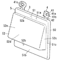
照明部8は、図4に示すように、口枠部7における左右方向と平行に配置される導光棒81と、導光棒81の左右方向の端面から光を入射させる光源82と、筐体9と、を備える。   As shown in FIG. 4, the illuminating unit 8 includes a light guide bar 81 arranged in parallel with the left and right direction of the mouth frame part 7, a light source 82 that makes light incident from the left and right end surfaces of the light guide bar 81, a housing And a body 9.

導光棒81は、左右方向に長く形成される長尺物であり、例えば、アクリルによって形成される。導光棒81の左右方向の両端面は入射面81aである。また、導光棒81の上端には光拡散部81bが設けられており、導光棒81の下方に臨む面が、出射面81cである。この導光棒81の出射面81cは、縦面部75に向くように配置される。   The light guide bar 81 is a long object that is formed long in the left-right direction, and is formed of, for example, acrylic. Both end surfaces of the light guide bar 81 in the left-right direction are incident surfaces 81a. In addition, a light diffusing portion 81b is provided at the upper end of the light guide bar 81, and a surface facing the lower side of the light guide bar 81 is an emission surface 81c. The light exit surface 81 c of the light guide bar 81 is disposed so as to face the vertical surface portion 75.

光源82は、入射面81aに対向するように配置される。本実施形態の光源82は、基板82aにLED82bが実装されて構成される。光源82は、本実施形態では、導光棒81の長手方向の両端に夫々一つづつ合計二つ設置されているが、その数は限定されない。   The light source 82 is disposed so as to face the incident surface 81a. The light source 82 of the present embodiment is configured by mounting an LED 82b on a substrate 82a. In the present embodiment, a total of two light sources 82 are installed at both ends in the longitudinal direction of the light guide rod 81, but the number is not limited.

筐体9は、導光棒81に沿って設けられた本体部91と、光源82を保持する光源保持部92と、を備える。   The housing 9 includes a main body portion 91 provided along the light guide rod 81 and a light source holding portion 92 that holds the light source 82.

本体部91は、下方に開口する断面略C字状となる。本体部91の下方の開口には、図4に示すように、透明板93が取り付けられている。透明板93は、導光棒81の出射面81cに対向配置される。   The main body 91 has a substantially C-shaped cross section that opens downward. As shown in FIG. 4, a transparent plate 93 is attached to the opening below the main body 91. The transparent plate 93 is disposed to face the light exit surface 81 c of the light guide bar 81.

光源保持部92は、図4に示すように、光源82を保持する有底筒状の基台部92aと、基台部92aに取り付けられて導光棒81を支持する支持部92bと、を有する。   As shown in FIG. 4, the light source holding unit 92 includes a bottomed cylindrical base 92 a that holds the light source 82, and a support 92 b that is attached to the base 92 a and supports the light guide rod 81. Have.

基台部92aは、導光棒81側に向かって開口する。基台部92aの奥面には、図4に示すように、光源82の基板82aが接触状態で取り付けられる。この基板82aは、光源82における熱発生部であり、基台部92aに熱的に接続される。   The base 92a opens toward the light guide bar 81 side. As shown in FIG. 4, a substrate 82a of a light source 82 is attached to the inner surface of the base portion 92a in a contact state. This board | substrate 82a is a heat generation part in the light source 82, and is thermally connected to the base part 92a.

また、基台部92aは、口枠部7に熱的に接続される。これにより、光源82から発生した熱は、基台部92aを介して口枠部7に伝導し放熱される。   In addition, the base portion 92 a is thermally connected to the mouth frame portion 7. Thereby, the heat generated from the light source 82 is conducted to the mouth frame portion 7 through the base portion 92a and radiated.

支持部92bは、基台部92aに嵌め込み固定される。そして、支持部92bは、導光棒81の端部を支持する。また、本実施形態の支持部92bは、光源82を覆う部分を有するので、透明な部材(例えば、アクリル)によって形成される。これにより、光源82から発せられた光は、支持部92bを透過して入射面81aに向かう。   The support portion 92b is fitted and fixed to the base portion 92a. The support portion 92 b supports the end portion of the light guide bar 81. Moreover, since the support part 92b of this embodiment has a part which covers the light source 82, it is formed with a transparent member (for example, acrylic). Thereby, the light emitted from the light source 82 passes through the support portion 92b and travels toward the incident surface 81a.

光源82から発せられた光は、入射面81aから入射し、導光棒81内において全反射を繰り返しながら導光棒81の長手方向に沿って進行する。このとき、光拡散部81bで反射した光は乱反射し、出射面81cから出射する。この出射面81cから出射した光は、透明板93を透過して縦面部75に向かう。これにより、光源82から発せられた光は縦面部75を照らす。   The light emitted from the light source 82 enters from the incident surface 81 a and travels along the longitudinal direction of the light guide bar 81 while repeating total reflection in the light guide bar 81. At this time, the light reflected by the light diffusion portion 81b is irregularly reflected and emitted from the emission surface 81c. The light emitted from the emission surface 81 c passes through the transparent plate 93 and travels toward the vertical surface portion 75. Thereby, the light emitted from the light source 82 illuminates the vertical surface portion 75.

上記した構成を備えた郵便受け1では、突出部52の上角部は、突出部52の下角部の位置よりも後方に位置し、投函物に突出部52の上角部が引っ掛かり難いので、ユーザーが郵便受け1に投函物を投函し易くなる。   In the mailbox 1 having the above-described configuration, the upper corner portion of the projecting portion 52 is located behind the position of the lower corner portion of the projecting portion 52, and the upper corner portion of the projecting portion 52 is not easily caught by the thrown object. However, it becomes easy to post a postal item to the mailbox 1.

さらに、上角部が引っ掛かることで発生する虞のある投函物の損傷を抑制することができる。   Furthermore, it is possible to suppress damage to the thrown object that may occur due to the upper corner portion being caught.

また、突出部52の下面部52bが、前開口21aの前端位置よりも前方に突出して設けられると、フラップ3にかかり傾斜面52eに沿って流下する雨水が、郵便受け本体2の内部に浸入し難くなる。   Further, when the lower surface portion 52b of the projecting portion 52 is provided so as to project forward from the front end position of the front opening 21a, rainwater flowing on the flap 3 along the inclined surface 52e enters the inside of the mail receiver main body 2. It becomes difficult.

本実施形態の郵便受け1は以下の構成を備える。   The mailbox 1 of the present embodiment has the following configuration.

郵便受け1は、箱状であり前面に前開口21aが設けられた郵便受け本体2と、前開口21aの周囲から前方に突出し、前端に前開口21aに通じる投入口74を有する口枠部7と、を備える。また、郵便受け1は、左右方向を軸方向とする回転軸の周りを回転し、郵便受け本体2の内側に配置されるフラップ3を備える。フラップ3は、その上端部に回転中心を有し、前開口21aに後方から近付いて閉塞し且つ、後側に回転することで前開口21aを開放する。フラップ3は、前開口21aを閉塞したとき前開口21aに挿入される突出部52を有する。突出部52の前面は、下側に行く程前側に位置するように傾斜する傾斜面52eとなることを特徴とする。   The mailbox 1 is a box-shaped mailbox body 2 having a front opening 21a provided on the front surface, a mouth frame portion 7 that protrudes forward from the periphery of the front opening 21a and has an insertion port 74 that communicates with the front opening 21a at the front end. Is provided. Further, the mailbox 1 includes a flap 3 that rotates around a rotation axis that has the left-right direction as an axial direction and is disposed inside the mailbox body 2. The flap 3 has a rotation center at its upper end, closes to the front opening 21a from behind, closes, and rotates to the rear side to open the front opening 21a. The flap 3 has a protrusion 52 that is inserted into the front opening 21a when the front opening 21a is closed. The front surface of the protrusion 52 is an inclined surface 52e that is inclined so as to be positioned on the front side as it goes downward.

これにより、厚みのある投函物を投入しても、投函物に突出部52の上角部が引っ掛かり難いため、投函物を投函し易くなる。   Thereby, even if a thick throwing thing is thrown in, since the upper corner part of the protrusion part 52 is hard to catch on a throwing thing, it becomes easy to throw a throwing thing.

口枠部7は、内側の下部に左右方向の全長に亘って設けられる縦面部75と、縦面部75と口枠部7の底板部72における内面72aとの間に形成される水抜き用隙間76と、を有することが好ましい。   The mouth frame part 7 has a drainage gap formed between the vertical surface part 75 provided on the inner lower part over the entire length in the left-right direction and the inner surface 72a of the vertical surface part 75 and the bottom plate part 72 of the mouth frame part 7. 76.

これにより、雨水除けの縦面部75を越えて雨水が浸入しても、雨水は水抜き用隙間76を通って口枠部7の外に排出される。   As a result, even if rainwater enters beyond the vertical surface portion 75 excluding rainwater, the rainwater is discharged out of the mouth frame portion 7 through the drainage gap 76.

口枠部7の底板部72における内面72aが、前側に行く程下側に位置するように傾斜することが好ましい。   It is preferable that the inner surface 72a of the bottom plate portion 72 of the mouth frame portion 7 is inclined so as to be positioned on the lower side as it goes to the front side.

これにより、口枠部7の底板部72における内面72aに付着した雨水が排出され易くなる。   Thereby, the rainwater adhering to the inner surface 72a in the bottom plate part 72 of the mouth frame part 7 is easily discharged.

縦面部75が表札であることが好ましい。   It is preferable that the vertical surface part 75 is a nameplate.

これにより、表札と郵便受け1が一体になるので外観をシンプルにすることができる。   Thereby, since a nameplate and the mailbox 1 are united, an external appearance can be simplified.

口枠部7の内側には、その上部で且つ縦面部75よりも前方に配置され、縦面部75に向かって発光する照明部8が設けられることが好ましい。   It is preferable that an illuminating unit 8 that is disposed on the upper side and in front of the vertical surface portion 75 and emits light toward the vertical surface portion 75 is provided inside the mouth frame portion 7.

これにより、縦面部75の表示が見え難くなるのを防ぐことができる。   Thereby, it can prevent that the display of the vertical surface part 75 becomes difficult to see.

照明部8は、口枠部7における左右方向と平行に配置される導光棒81と、導光棒81の左右方向の端面から光を入射させる光源82と、を備える。照明部8では、導光棒81における縦面部75に向く面が出射面81cであることが好ましい。   The illuminating unit 8 includes a light guide bar 81 arranged in parallel with the left-right direction in the mouth frame part 7 and a light source 82 that makes light incident from an end surface of the light guide bar 81 in the left-right direction. In the illumination part 8, it is preferable that the surface which faces the vertical surface part 75 in the light-guide rod 81 is the output surface 81c.

これにより、光源82が点光源であったとしても、線状に発光させることができ、縦面部75を効果的に照らすことができる。   Thereby, even if the light source 82 is a point light source, it can be made to emit light linearly and the vertical surface part 75 can be illuminated effectively.

照明部8では、光源82が口枠部7に熱的に接続され、口枠部7を介して放熱する構成であることが好ましい。   The illumination unit 8 preferably has a configuration in which the light source 82 is thermally connected to the mouth frame part 7 and radiates heat through the mouth frame part 7.

これにより、光源82が熱の影響を受けるのを防ぐことができる。   Thereby, it is possible to prevent the light source 82 from being affected by heat.

1 郵便受け
2 郵便受け本体
21a 前開口
23 側面部
23b フラップ用軸部
3 フラップ
4 軸受け部
5 フラップ本体
52 突出部
52e 傾斜面
7 口枠部
74 投入口
75 縦面部
76 水抜き用隙間
8 照明部
81 導光棒
82 光源
9 筐体
DESCRIPTION OF SYMBOLS 1 Mailbox 2 Mailbox main body 21a Front opening 23 Side part 23b Flap shaft part 3 Flap 4 Bearing part 5 Flap main body 52 Projection part 52e Inclined surface 7 Mouth frame part 74 Input port 75 Vertical surface part 76 Water gap 8 Illumination part 81 Guide Light stick 82 Light source 9 Case

Claims (5)

箱状であり前面に前開口が設けられた郵便受け本体と、
前記前開口の周囲から前方に突出し、前端に前記前開口に通じる投入口を有する口枠部と、
左右方向を軸方向とする回転軸の周りを回転し、前記郵便受け本体の内側に配置されるフラップと、を備え、
前記フラップは、
その上端部に回転中心を有し、前記前開口に後方から近付いて閉塞し且つ、後側に回転することで前記前開口を開放するものであり、
前記フラップは、
前記前開口を閉塞したとき前記前開口に挿入される突出部を有し、
前記突出部の前面は、下側に行く程前側に位置するように傾斜する傾斜面となり、
前記口枠部は、内側の下部に左右方向の全長に亘って設けられる縦面部を有し、
前記口枠部の内側には、その上部で且つ前記縦面部よりも前方に配置され、前記縦面部に向かって発光する照明部が設けられ、
前記照明部は、
前記口枠部における左右方向と平行に配置される導光棒と、
前記導光棒の左右方向の端面から光を入射させる光源と、を備え、
前記導光棒における前記縦面部に向く面が出射面であることを特徴とする郵便受け。
A mailbox with a box shape and a front opening on the front;
A mouth frame portion that protrudes forward from the periphery of the front opening and has an insertion port that communicates with the front opening at a front end;
A flap that rotates around a rotation axis having an axial direction in the left-right direction and is disposed inside the mailbox body,
The flap is
It has a center of rotation at its upper end, closes and closes the front opening from behind, and opens the front opening by rotating to the rear side.
The flap is
Having a protrusion inserted into the front opening when the front opening is closed;
Front surface of the protrusion, Ri Do an inclined surface inclined so as to be positioned in front enough to go lower,
The mouth frame part has a vertical surface part provided over the entire length in the left-right direction at the inner lower part,
On the inner side of the mouth frame part, an illuminating part that is arranged at the upper part and in front of the vertical surface part and emits light toward the vertical surface part is provided,
The illumination unit is
A light guide rod arranged in parallel with the left-right direction in the mouth frame part,
A light source that makes light incident from an end surface in the left-right direction of the light guide rod, and
Maildrop surface facing the longitudinal face of the light guide rod and said exit surface der Rukoto.
前記口枠部は、前記縦面部と前記口枠部の底板部における内面との間に形成される水抜き用隙間を有することを特徴とする請求項1に記載の郵便受け。 The opening frame section, letterbox according to claim 1, characterized in that it has a between water-removal gap formed between the inner surface and before Kitate surface portion and the bottom plate portion of the opening frame section. 前記口枠部の底板部における内面が、前側に行く程下側に位置するように傾斜することを特徴とする請求項1又は請求項2に記載の郵便受け。   The mailbox according to claim 1 or 2, wherein an inner surface of the bottom plate portion of the mouth frame portion is inclined so as to be positioned on the lower side as going to the front side. 前記縦面部が表札であることを特徴とする請求項1〜3のいずれか一項に記載の郵便受け。 The mailbox according to any one of claims 1 to 3, wherein the vertical surface portion is a nameplate. 前記照明部では、前記光源が前記口枠部に熱的に接続され、前記口枠部を介して放熱する構成であることを特徴とする請求項1〜4のいずれか一項に記載の郵便受け 5. The postbox according to claim 1, wherein the illumination unit has a configuration in which the light source is thermally connected to the mouth frame part and radiates heat through the mouth frame part. .
JP2015003970A 2015-01-13 2015-01-13 Mailbox Expired - Fee Related JP6601751B2 (en)

Priority Applications (1)

Application Number Priority Date Filing Date Title
JP2015003970A JP6601751B2 (en) 2015-01-13 2015-01-13 Mailbox

Applications Claiming Priority (1)

Application Number Priority Date Filing Date Title
JP2015003970A JP6601751B2 (en) 2015-01-13 2015-01-13 Mailbox

Publications (2)

Publication Number Publication Date
JP2016129539A JP2016129539A (en) 2016-07-21
JP6601751B2 true JP6601751B2 (en) 2019-11-06

Family

ID=56414905

Family Applications (1)

Application Number Title Priority Date Filing Date
JP2015003970A Expired - Fee Related JP6601751B2 (en) 2015-01-13 2015-01-13 Mailbox

Country Status (1)

Country Link
JP (1) JP6601751B2 (en)

Families Citing this family (2)

* Cited by examiner, † Cited by third party
Publication number Priority date Publication date Assignee Title
JP2018139763A (en) * 2017-02-27 2018-09-13 パナソニックIpマネジメント株式会社 Parcel receiving box
JP6506812B2 (en) * 2017-10-06 2019-04-24 日立オートモティブシステムズ株式会社 Vehicle motion control device and motion control program

Family Cites Families (12)

* Cited by examiner, † Cited by third party
Publication number Priority date Publication date Assignee Title
GB905036A (en) * 1959-08-31 1962-09-05 Frederick Valentine William Se Improvements relating to letter plates
JPS5457099U (en) * 1977-09-28 1979-04-20
JPS56106612A (en) * 1980-01-31 1981-08-25 Matsushita Electric Works Ltd Mail box
JPS57141578U (en) * 1981-02-27 1982-09-04
JPS6131281U (en) * 1984-07-31 1986-02-25 三和シヤツタ−工業株式会社 Drainage structure at the mailbox
JPH0788035A (en) * 1993-09-24 1995-04-04 Toyo Exterior Co Ltd Device for preventing rainwater from entering mailbox
JPH08140822A (en) * 1994-11-17 1996-06-04 Toyo Exterior Co Ltd Article insertion port
JP3055442U (en) * 1998-06-30 1999-01-12 アイリスオーヤマ株式会社 post
JP3146161U (en) * 2008-08-26 2008-11-06 株式会社ダイケン Mail receiver
JP2010267590A (en) * 2009-05-18 2010-11-25 Panasonic Electric Works Co Ltd Display lamp
JP2012079673A (en) * 2011-01-27 2012-04-19 Tousui Ltd Led lighting lamp
JP6120138B2 (en) * 2013-01-18 2017-04-26 スタンレー電気株式会社 License plate lighting device

Also Published As

Publication number Publication date
JP2016129539A (en) 2016-07-21

Similar Documents

Publication Publication Date Title
JP6601751B2 (en) Mailbox
JP2008104637A (en) Game machine
JP2011077637A (en) Image display device
JP6745469B2 (en) Mailbox
JP6177121B2 (en) Lighting device and storage device
JP4531727B2 (en) Game machine
JP2009045248A (en) Post
JP6369781B2 (en) Mailbox
JP5562476B1 (en) Display device using vending machine for capsules
JP6512504B2 (en) Mail box
JP6467749B2 (en) Mailbox
JP2006288811A5 (en)
JP2016112083A (en) Mailbox
US1106376A (en) Combined mail-box.
JP7379632B2 (en) Fire hydrant equipment, fire extinguisher box
JP6485768B2 (en) Mailbox
KR200424747Y1 (en) Vending Machine
JP2008023157A (en) Pinball game machine
JP6443796B2 (en) Mailbox
JP2014200416A (en) Mailbox
JP6541054B2 (en) Mailbox, and installation structure of the mailbox
JP6675087B2 (en) Post box mounting structure
JP2005040336A (en) Prize-winning device of pachinko machine
US444211A (en) Engineer s order bulletin-board
JP2013213324A (en) Functional gatepost

Legal Events

Date Code Title Description
RD02 Notification of acceptance of power of attorney

Free format text: JAPANESE INTERMEDIATE CODE: A7422

Effective date: 20170208

A621 Written request for application examination

Free format text: JAPANESE INTERMEDIATE CODE: A621

Effective date: 20171120

A977 Report on retrieval

Free format text: JAPANESE INTERMEDIATE CODE: A971007

Effective date: 20180822

A131 Notification of reasons for refusal

Free format text: JAPANESE INTERMEDIATE CODE: A131

Effective date: 20180918

A131 Notification of reasons for refusal

Free format text: JAPANESE INTERMEDIATE CODE: A131

Effective date: 20190423

A521 Request for written amendment filed

Free format text: JAPANESE INTERMEDIATE CODE: A523

Effective date: 20190527

TRDD Decision of grant or rejection written
A01 Written decision to grant a patent or to grant a registration (utility model)

Free format text: JAPANESE INTERMEDIATE CODE: A01

Effective date: 20190903

A61 First payment of annual fees (during grant procedure)

Free format text: JAPANESE INTERMEDIATE CODE: A61

Effective date: 20190927

R151 Written notification of patent or utility model registration

Ref document number: 6601751

Country of ref document: JP

Free format text: JAPANESE INTERMEDIATE CODE: R151

LAPS Cancellation because of no payment of annual fees