JP6601461B2 - Vehicle occupant restraint system - Google Patents
Vehicle occupant restraint system Download PDFInfo
- Publication number
- JP6601461B2 JP6601461B2 JP2017135194A JP2017135194A JP6601461B2 JP 6601461 B2 JP6601461 B2 JP 6601461B2 JP 2017135194 A JP2017135194 A JP 2017135194A JP 2017135194 A JP2017135194 A JP 2017135194A JP 6601461 B2 JP6601461 B2 JP 6601461B2
- Authority
- JP
- Japan
- Prior art keywords
- occupant
- side wall
- wall portion
- seat belt
- belt
- Prior art date
- Legal status (The legal status is an assumption and is not a legal conclusion. Google has not performed a legal analysis and makes no representation as to the accuracy of the status listed.)
- Expired - Fee Related
Links
Images


Description
本発明は、車両用乗員拘束装置に関するものである。 The present invention relates to an occupant restraint device for a vehicle.
車両においては、各座席毎に、衝突時の乗員保護のためにシートベルト装置を装備するのが一般的となっている。車両用のシートベルト装置は、いわゆる3点式が一般的となっており、乗員の左右一方の肩部付近に配設されたベルトガイドを経由したシートベルトが、乗員の一方の肩部から斜め下方へと延びて乗員を拘束するようになっている。また、車両の衝突時にシートベルトの弛みを低減するために、シートベルトを巻き取るリトラクタがプリテンショナ式とされていることも一般的となっており、さらにシートベルトによる締付力が所定値以上とならないようにロードリミッタを有するものも一般的となっている。 In vehicles, it is common to equip each seat with a seat belt device to protect passengers in the event of a collision. A so-called three-point system is generally used for a seat belt device for a vehicle, and a seat belt that passes through a belt guide disposed in the vicinity of one of the left and right shoulders of an occupant is inclined from one shoulder of the occupant. It extends downward and restrains the occupant. In order to reduce seat belt slack in the event of a vehicle collision, the retractor that winds up the seat belt is generally a pretensioner type, and the tightening force by the seat belt exceeds a predetermined value. In order to prevent this, a load limiter is also commonly used.
特許文献1には、前方衝突時に、シートベルトアンカあるいはベルトガイドを乗員側に向けて変位させることにより、シートベルトによる胸たわみ(肋骨の変形)を抑制するものが開示されている。特許文献2のものでは、ベルトガイドに関して、ベルトガイドを乗員側に付勢するスプリングと、通常時は乗員側に向けて移動するのを規制するピストン・シリンダを利用したストッパ機構とを用いて、前方衝突時にストッパ機構を解除してベルトガイドを乗員側に移動させるものが開示されている(段落番号0034、0035)。また、特許文献2には、別の例として、インフレータの爆発力を利用してベルトガイドを乗員側に付勢することも開示されている(段落番号0040)。
特許文献2には、ベルトガイドを、乗員の好みに応じて、マニュアル操作によって車幅方向位置を調整可能としたものが開示されている。
ところで、最近では、6才・12才程度の子供用として、シートクッション上に載置固定されるブースタシートを用いるものがある。このブースタシートに着座した子供は、その肩の高さが、シートクッションに直接着座した大人の肩の高さとほぼ同じとなるため、シートベルト装置を大人用と子供用とで兼用できるようになる。 By the way, recently, there are some which use a booster seat that is placed and fixed on a seat cushion for children of about 6 and 12 years old. The child seated in this booster seat has almost the same height as the shoulder of an adult seated directly on the seat cushion, so the seat belt device can be used for both adults and children. .
上記のように、シートベルトを、大人用とブースタシートに着座した子供用とで兼用した場合、子供の肩幅は大人の肩幅に比して小さいため、シートベルトが子供の肩から外れやすくなる。前方衝突時、特にベルトガイドとは反対側に子供が投げ出されようとする斜め衝突時に、子供の肩からシートベルトが外れやすいものとなる。 As described above, when the seat belt is used for both an adult and a child seated on a booster seat, the child's shoulder width is smaller than the shoulder width of the adult, so the seat belt is easily detached from the child's shoulder. At the time of a forward collision, in particular, at the time of an oblique collision in which the child is about to be thrown out on the side opposite to the belt guide, the seat belt is easily detached from the child's shoulder.
このため、子供がシートベルトを着用することを想定して、あらかじめベルトガイドを通常時よりも乗員側(乗員の首に近い側)に設置することも考えられる。しかしながら、この場合は、大人がシートベルトを着用した際に、シートベルトが首の近くに位置して、装着感が極めて悪いものになってしまう。 For this reason, it is also conceivable that the belt guide is installed in advance on the occupant side (side closer to the occupant's neck) than usual, assuming that the child wears a seat belt. However, in this case, when an adult wears a seat belt, the seat belt is located near the neck, and the feeling of wearing becomes extremely bad.
上記のことから、特許文献1に記載のように、前方衝突時にベルトガイドを乗員側に移動させることが考えられる。しかしながら、ベルトガイドの移動のために、スプリングとピストン・シリンダからなるストッパ機構とを用いたり、インフレータを用いることは高価な部品の使用となり好ましくない。
From the above, as described in
また、特許文献2に記載のように、ベルトガイドの車幅方向位置をマニュアル調整することも考えられる。しかしながら、マニュアル操作によってベルトガイドの位置を調整するのは面倒であり、またこの調整を忘れてしまうことも応々にして生じやすいものとなる。
Further, as described in
本発明は以上のような事情を勘案してなされたもので、その目的は、高価な部品の追加や別途マニュアル操作を行うことなく、大人が装着したときの装着感悪化の防止と、子供が装着したときの衝突時におけるシートベルトの肩外れ防止とを、共に得られるようにした車両用乗員拘束装置を提供することにある。 The present invention has been made in consideration of the above circumstances, and its purpose is to prevent the deterioration of the wearing feeling when an adult is wearing, without adding expensive parts or manual operation separately, and It is an object of the present invention to provide an occupant restraint device for a vehicle that can prevent shoulder detachment of a seat belt at the time of a collision when it is worn.
前記目的を達成するため、本発明にあっては次のような基本的な解決手法を採択してある。すなわち、請求項1〜請求項4に記載のように、
乗員の左右一方の肩部付近に配設されたベルトガイドの後方にプリテンショナ式のリトラクタが配設され、該リトラクタから該ベルトガイドを経由したシートベルトが乗員の肩部から斜め下方へと延びて乗員を拘束するようにされた車両用乗員拘束装置であって、
前記ベルトガイドは、乗員側の端部において上方へ延びる内側側壁部を有し、
前記内側側壁部は、通常時はシートベルトが乗員側に向けて所定以上変位するのを規制しており、
前記内側側壁部は、前記シートベルトに対して前記リトラクタによるプリテンションの引張力が作用したときに、該引張力のうち乗員側への分力を受けて乗員側に向けて弾性変形されて、シートベルトが通常時よりも乗員側に向けて変位された位置とされる、
ようにしてある。
上記基本的な解決手法に加えて、本発明にあってはさらに次のような具体的な解決手法を採択してある。すなわち、
請求項1に記載された発明においては、前記ベルトガイドを構成する材質のうち、前記内側側壁部を構成する材質と他の部位を構成する材質とが相違されて、該内側側壁部を構成する材質が該他の部位を構成する材質に比して相対的に弾性変形しやすくされている、ようにしてある。
請求項2に記載された発明においては、前記内側側壁部が前記弾性変形されたときに、前記シートベルトの少なくとも一部が該内側側壁部を乗り越えて乗員側に向けて変位可能とされている、ようにしてある。
請求項3に記載された発明においては、
前記ベルトガイドは、乗員側とは反対側の端部において、上方へ延びる外側側壁部を有し、
前記内側側壁部の高さが、前記外側側壁部の高さよりも高くされている、
ようにしてある。
請求項4に記載された発明においては、
前記ベルトガイドは、乗員側とは反対側の端部において、上方へ延びる外側側壁部を有し、
前記外側側壁部は、その上端部が乗員側に向かうように指向された屈曲部を有し、
前記屈曲部の指向方延長線が、前記内側側壁部の上端よりも低い位置を通るように設定されている、
ようにしてある。
本発明の好ましい態様は、請求項5以下に記載のとおりである。
In order to achieve the above object, the following basic solution is adopted in the present invention. That is, as described in
A pretensioner type retractor is disposed behind the belt guide disposed in the vicinity of one of the left and right shoulders of the occupant, and the seat belt passing through the belt guide extends obliquely downward from the shoulder of the occupant. A vehicle occupant restraint device adapted to restrain the occupant
The belt guide has an inner side wall portion extending upward at an end portion on the passenger side,
The inner side wall portion normally restricts the seat belt from being displaced more than a predetermined amount toward the occupant side,
The inner side wall portion is elastically deformed toward the occupant side by receiving a component force toward the occupant side of the tensile force when a tension force of the pretension by the retractor acts on the seat belt, The seat belt is a position displaced toward the occupant side than normal,
It is like that.
In addition to the above basic solution method, the present invention further adopts the following specific solution method. That is,
In the invention described in
In the invention described in
In the invention described in claim 3,
The belt guide has an outer side wall portion extending upward at an end opposite to the passenger side,
The height of the inner side wall is higher than the height of the outer side wall,
It is like that.
In the invention described in claim 4,
The belt guide has an outer side wall portion extending upward at an end opposite to the passenger side,
The outer side wall portion has a bent portion whose upper end portion is directed toward the occupant side,
The directional extension line of the bent portion is set to pass through a position lower than the upper end of the inner side wall portion,
It is like that.
Preferred embodiments of the present invention are as set forth in
上記解決手法によれば、通常時は、シートベルトが大人の乗員の首に近すぎない位置となるようにして、シートベルトの装着感を良好なものとすることができる。また、前方衝突時には、シートベルトが乗員側へ移動されるので、乗員が子供の場合にシートベルトが肩外れしてしまう事態を防止することができる。さらに、ベルトガイドの乗員側への移動は、プリテンションによる引張力を有効に利用してベルトガイドの内側側壁部を弾性変形させることによって行うので、構造も極めて簡単となる。さらに又、ベルトガイドの車幅方向位置の調整をマニュアル操作によって行う必要もないので、取り扱いが容易であり、しかも位置調整のし忘れという事態も生じないものである。以上に加えて、プリテンションによる引張力は所定の一定値として期待できるので、内側側壁部を乗員側へ弾性変形させてシートベルトを乗員側へ移動させるという作動を確実に得る上で好ましいものとなる。
以上に加えて、請求項1に記載の発明においては、材質を部分的に相違させるという簡単な手法により、プリテンションの引張力に基づく内側側壁部の弾性変形を容易かつ確実に行わせることができる。
請求項2に記載の発明においては、シートベルトの乗員側への移動を大きく確保する上で好ましいものとなる。
請求項3に記載の発明においては、内側側壁部の高さを十分に確保して、通常時にシートベルトが内側側壁部を乗り越えてしまうような事態を防止しつつ、前方衝突時にはプリテンションの引張力を確実に内側側壁部に伝達させて当該内側側壁部を乗員側へ向けて弾性変形させる上で好ましいものとなる。
請求項4に記載の発明においては、内側側壁部の高さを十分に確保して、通常時にシートベルトが内側側壁部を乗り越えてしまうような事態を防止しつつ、通常時において、シートベルトが外側側壁部を乗り越えてしまうような事態を防止する上でも好ましいものとなる。
According to the above solution, the seat belt can be placed in a position that is not too close to the neck of an adult occupant in a normal state, so that the feeling of wearing the seat belt can be improved. Further, since the seat belt is moved to the occupant side at the time of a frontal collision, it is possible to prevent a situation in which the seat belt comes off the shoulder when the occupant is a child. Further, the movement of the belt guide toward the occupant side is performed by elastically deforming the inner side wall portion of the belt guide by effectively utilizing the tensile force due to the pretension, and thus the structure becomes very simple. Furthermore, since it is not necessary to adjust the position of the belt guide in the vehicle width direction by manual operation, the handling is easy, and the situation of forgetting to adjust the position does not occur. In addition to the above, since the tensile force due to the pretension can be expected as a predetermined constant value, it is preferable for reliably obtaining the operation of elastically deforming the inner side wall portion toward the occupant side and moving the seat belt toward the occupant side. Become.
In addition to the above, in the first aspect of the invention, it is possible to easily and surely perform elastic deformation of the inner side wall portion based on the tensile force of the pretension, by a simple method of partially different materials. it can.
In invention of
In the invention according to claim 3, the height of the inner side wall portion is sufficiently secured to prevent a situation in which the seat belt gets over the inner side wall portion at the normal time, and the tension of the pretension is applied at the time of a forward collision. This is preferable for reliably transmitting the force to the inner side wall portion and elastically deforming the inner side wall portion toward the occupant.
In the invention according to claim 4, the seat belt is secured at a normal time while ensuring a sufficient height of the inner side wall portion to prevent a situation in which the seat belt normally gets over the inner side wall portion. This is also preferable in preventing a situation where the outer side wall portion is overcome.
請求項5に記載の発明においては、前記内側側壁部の弾性変形を助長させる弱化部が、該内側側壁部または該内側側壁部付近に形成されている、ようにしてあるので、プリテンションの引張力に基づく内側側壁部の弾性変形を容易かつ確実に行わせることができる。
In the invention of
請求項6に記載の発明においては、前記内側側壁部のうち少なくともその基端部が、上方に向かうにつれて徐々に乗員側へ向かうように傾斜されている、ようにしてあるので、前方衝突時に、シートベルトの乗員側に向けての移動を助長させる上で好ましいものとなる。 In the invention of claim 6, at least the proximal end of the inner side wall portion is inclined toward the gradually occupant side toward upwardly, so way are, before side collision This is preferable for promoting the movement of the seat belt toward the passenger.
本発明によれば、高価な部品の追加や別途マニュアル操作を行うことなく、大人が装着したときの装着感悪化の防止と、子供が装着したときの衝突時におけるシートベルトの肩外れ防止とを、共に満足させることができる。 According to the present invention, it is possible to prevent deterioration of the feeling of wearing when an adult is worn without adding expensive parts or performing manual operation separately, and to prevent the shoulder of the seat belt from falling off at the time of collision when a child is worn. Both can be satisfied.
図1において、後席用のシートSが、シートクッション1とシートバック2とヘッドレスト3とを有する。図1では、シートSのうち右側端部の部分を示し、大人P1がシートクッション1に着座されている。
In FIG. 1, a rear seat S includes a
シートバック2の右上端部に、ベルトガイド10が固定されている。このベルトガイド10の後方に、リトラクタ30が固定配置されている。リトラクタ30のベルト引き出し口30aから引き出されたシートベルト40が、ほぼまっすぐ前方へ延びた後、ベルトガイド10を経由して、大人P1の肩部(右肩部)から斜め下方へ延びるように配設されて、大人P1を拘束している。シートベルト40は、その先端部が大人P1の右下方付近にある車体に固定されると共に、その中間部に設けたタング(図示略)が、大人P1の左腰付近にあるロック装置に着脱自在に係合されている。このように、シートベルト装置は3点式とされている。
A
リトラクタ30は、プリテンショナ式とされて、車両の衝突時、すなわち前方衝突時や車体前部のうち左右端部付近が衝突する斜め衝突時に、シートベルト40を所定の引張力でもってリトラクタ10側に引き込んで、シートベルト40によって大人P1を確実に拘束する。また、リトラクタ30は、ロードリミッタ式とされて、シートベルト40によって大人P1を所定値以上の締付力でもって拘束しないようにされる。
The
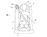
図2は、シートクッション1上に、ブースタシート5が配設されて、このブースタシート5上に子供P2(6才・12才程度の子供を想定)が着座されている。子供P2も、シートベルト40によって拘束されている。
In FIG. 2, a
図1、図2を比較して明かなように、大人P1とブースタシート5上の子供P2とは、その肩の高さ位置がほぼ同じとされている。この一方、大人P1と子供P2とでは肩幅が大きく相違する。したがって、拘束時におけるシートベルト40は、肩付近の高さ位置では、大人P1においては首と右肩との間の好ましい位置とされる一方、子供P2においては右肩近くに位置されてしまうことになる。
As is clear from comparison between FIGS. 1 and 2, the height of the shoulders of the adult P1 and the child P2 on the
図1、図2は、ベルトガイド40が、その車幅方向位置が、大人P1にとって好ましい位置設定とされている。しかしながら、子供P2においては、シートベルト40が右肩付近に位置されていることから、シートベルト40が右肩から外れて、シートベルト40による拘束が解除されやすいものとなる。特に、車両の左前部が衝突する斜め衝突時には、図2矢印αで示すように、子供P2は前方のみならず左方側へ向かう方向へと投げ出されようとすることから、シートベルト40が子供P2の右肩から外れやすいものとなる。このような現象は、ベルトガイド40が乗員の左肩付近に配設される場合も同様に生じる(車体前部のうち、乗員を挟んでベルトガイドと反対側の端部が衝突する斜め衝突時にシートベルトの肩外れが発生しやすい)。
In FIG. 1 and FIG. 2, the position of the
子供P2について、シートベルト40が肩外れしてしまうことを防止するために、ベルトガイド10を図1、図2に示す位置よりも乗員側に近づける(図1、図2右方側に移動させた位置とする)ことも考えられる。しかしながら、この場合は、大人P1においては、通常時において、シートベルト40が首の近くになってしまい、装着感の悪いものとなる。
In order to prevent the
本発明では、ベルトガイド10の変形を利用して、大人P1については通常時での装着感を良好にする(悪化させない)一方、子供P2については衝突時におけるシートベルト40の肩外れを防止できるようにしてある。
In the present invention, the deformation of the
以下、図5・図9を参照しつつ、ベルトガイド10の詳細について説明するが、ベルトガイド10は全体的に合成樹脂による一体成形品とされている。ベルトガイド10は、固定具20によってシートバック2(におけるフレーム)の上端部等に固定される板状の固定部11と、固定部11の前端部に連なるように形成された下ガイド部12と、外側側壁部13と、内側側壁部14と、を有する。
Hereinafter, the details of the
下ガイド部12は、シートベルト40の滑りがよくなくように平滑面とされて(滑り易い部材を塗布、コーティングすることもできる)、シートベルト40の幅よりも十分大きな幅とされている。そして、下ガイド部12(の上面)の高さ位置は、図4に示すように、リトラクタ30のベルト引き出し口30aの高さ位置とほぼ同じ高さとなるように設定されている。
The
外側側壁部13は、下ガイド部12のうち車幅方向外側(乗員としての大人P1あるいは子供P2が位置する側とは車幅方向反対側)の端部から、上方側へ延びている。内側側壁部14は、下ガイド部12のうち乗員側の端部から上方側へ延びている。
The outer
各側壁部13、14は、通常時において、シートベルト40が、ベルトガイド10(の下ガイド部12)から車幅方向に外れるのを規制する。実施形態では、外側側壁部13は、一端短く上方へ延びた後、乗員側へ向けて斜め上方に延びる屈曲部13aを有する。
The
内側側壁部14は、上方に向かうにつれて乗員側に近づくように傾斜されている。より具体的には、内側側壁部14の内面14aが、上方に向かうにつれて乗員側に近づくように傾斜されている。この傾斜により、シートベルト40のうち下ガイド部12上にある部分が、乗員側へ向けて容易に移動しやすくなるようにされている。ただし、通常時においては、シートベルト40が乗員による引張操作等によって多少乗員側へ向かうような力を受けても、シートベルト40が内側側壁部14を乗り越えないように当該内側側壁部14の高さが設定されている。
The inner
ここで、内側側壁部14の高さは、外側側壁部13の高さよりも高くされている。また、外側側壁部13の屈曲部13aが指向する方向の延長線が、内側側壁部14の上端よりも低い位置を通るようにされている。
Here, the height of the inner
内側側壁部14は、リトラクタ30からのプリテンションによって後方への引張力を受けた際に、乗員側へと容易に弾性変形されるように設定されている。実施形態では、内側側壁部14を構成する部分(下ガイド部12から上方へ延びる部分)の材質が、他の部分を構成する材質とは相違されて、より弾性変形しやすくなるものが用いられている(例えば2色成形による内側側壁部14と他の部分とを一体成形)。
The inner
乗員を拘束しているシートベルト40は、通常時(プリテンションによる引張力が作用していない状態)においては、図10に示すように、下ガイド部12上に位置されて、内側側壁部14の底部側に位置される。これにより、通常時には、乗員としての大人P1については、シートベルト40が図1に示すようにその首から離れた状態とされて、シートベルト40を装着していることによる装着感の悪化が生じないものとされる。
The
車両の衝突時には、プリテンショナが作動することにより、シートベルト40に対してリトラクタ30に引き込まれる方向の大きな引張力が作用する。この引張力は、シートベルト40に対して、ベルトガイド10上において乗員側へ向かうような分力を発生させる。この分力はかなり大きな力となるので、シートベルト40は、図11に示すように内側側壁部14を乗員側に向けて弾性変形させつつ、乗員側へ移動される。このシートベルト40の乗員側の移動によって、特に乗員が子供P2の場合にその肩からシートベルト40が外れてしまうことが防止される。なお、上記引張力に伴うシートベルト40の乗員側の移動は、内側側壁部14を乗り越えない範囲で行われるようにしてもよく、あるいは内側側壁部14を乗り越える大きなものとすることもできる。
When the vehicle collides, the pretensioner is activated, and a large tensile force in the direction of being retracted into the
図12・図15は、それぞれ、ベルトガイド10の変形例を示すもので、内側側壁部の乗員側に向けての弾性変形を助長させるための例を示す。図12に示すベルトガイド10Bは、内側側壁部14の底部(基部)のうち乗員側の面に、弱化部としての切欠15を形成したものとなっている。切欠15の形成によって、シートベルト40から同じ大きさの乗員側に向けての外力(前述した分力)を受けた際に、内側側壁部14がより一層容易に乗員側に向けて弾性変形される。
12 and 15 each show a modification of the
図13に示すベルトガイド10Cは、内側側壁部14の底部(基部)のうち前面に、弱化部としての切欠16を形成したものとなっている。
The
図14に示すベルトガイド10Dは、内側側壁部14の基部内に延びる弱化部としてのスリット17を形成したものとなっている。
The
図15に示すベルトガイド10Eは、内側側壁部14B(14対応)の形状を、図5・図9に示す実施形態の場合に比して、その上部に乗員とは反対側に折り返されて略渦巻き形状とされた折り返し部14Baを形成してある。また、外側側壁部13B(13対応)については、図5・図9に示す実施形態における屈曲部をさらに延長した屈曲部13Baを有するようにし、かつ屈曲部13Baの先端部13Bbを、内側側壁部14Bにおける折り返し部14Baと相対向させるように下方に向けて傾斜させてある。そして、内側側壁部14Bの前面に、内側側壁部14Bに沿って細長く延びる弱化部としての凹部18を形成してある。本実施形態では、シートベルト40がベルトガイド10Eから外れてしまうのをより確実に防止できる。また、プリテンションの引張力を受けた際に、内側側壁部14Bを乗員側へ弾性変形させる分力が、内側側壁部14Bのより高い位置に作用されることから、内側側壁部14B(の特に上端部)を十分に乗員側へ弾性変形させて、シートベルト40を容易に乗員側へと移動させることができる。
The
以上実施形態について説明したが、本発明は、実施形態に限定されるものではなく、特許請求の範囲の記載された範囲において適宜の変更が可能である。前席用としても適用できる(特に2シータ車)。勿論、本発明の目的は、明記されたものに限らず、実質的に好ましいあるいは利点として表現されたものを提供することをも暗黙的に含むものである。 Although the embodiments have been described above, the present invention is not limited to the embodiments, and appropriate modifications can be made within the scope of the claims. It can also be used for front seats (especially 2-theta vehicles). Of course, the object of the present invention is not limited to what is explicitly stated, but also implicitly includes providing what is substantially preferred or expressed as an advantage.
本発明は、車両のシートベルトとして好適である。 The present invention is suitable as a seat belt for a vehicle.
P1:大人(乗員)
P2:子供(乗員)
S:シート
1:シートクッション
2:シートバック
5:ブースタシート
10:ベルトガイド
10B:ベルトガイド(図12)
10C:ベルトガイド(図13)
10D:ベルトガイド(図14)
10E:ベルトガイド(図15)
11:固定部
12:下ガイド部
13:外側側壁部
13a:屈曲部
14:内側側壁部
14a:内面
14Ba:折り返し部(図15)
15:切欠(図12で、弱化部)
16:切欠(図13で、弱化部)
17:スリット(図14で、弱化部)
18:凹部(図15で、弱化部)
20:固定具
30:リトラクタ
30a:ベルト引き出し口
40:シートベルト
P1: Adult (occupant)
P2: Child (crew)
S: Seat 1: Seat cushion 2: Seat back 5: Booster seat 10:
10C: Belt guide (FIG. 13)
10D: belt guide (FIG. 14)
10E: belt guide (FIG. 15)
11: Fixed part 12: Lower guide part 13: Outer
15: Notch (weakened part in FIG. 12)
16: Notch (weakened part in FIG. 13)
17: Slit (weakened part in FIG. 14)
18: Concave portion (weakened portion in FIG. 15)
20: Fixing tool 30:
Claims (6)
前記ベルトガイドは、乗員側の端部において上方へ延びる内側側壁部を有し、
前記内側側壁部は、通常時はシートベルトが乗員側に向けて所定以上変位するのを規制しており、
前記内側側壁部は、前記シートベルトに対して前記リトラクタによるプリテンションの引張力が作用したときに、該引張力のうち乗員側への分力を受けて乗員側に向けて弾性変形されて、シートベルトが通常時よりも乗員側に向けて変位された位置とされ、
前記ベルトガイドを構成する材質のうち、前記内側側壁部を構成する材質と他の部位を構成する材質とが相違されて、該内側側壁部を構成する材質が該他の部位を構成する材質に比して相対的に弾性変形しやすくされている、
ことを特徴とする車両用乗員拘束装置。 A pretensioner type retractor is disposed behind the belt guide disposed in the vicinity of one of the left and right shoulders of the occupant, and the seat belt passing through the belt guide extends obliquely downward from the shoulder of the occupant. A vehicle occupant restraint device adapted to restrain the occupant
The belt guide has an inner side wall portion extending upward at an end portion on the passenger side,
The inner side wall portion normally restricts the seat belt from being displaced more than a predetermined amount toward the occupant side,
The inner side wall portion is elastically deformed toward the occupant side by receiving a component force toward the occupant side of the tensile force when a tension force of the pretension by the retractor acts on the seat belt, The seat belt is a position displaced toward the occupant side than usual ,
Among the materials constituting the belt guide, the material constituting the inner side wall portion is different from the material constituting the other portion, and the material constituting the inner side wall portion is the material constituting the other portion. It is relatively easy to elastically deform,
An occupant restraint device for a vehicle.
前記ベルトガイドは、乗員側の端部において上方へ延びる内側側壁部を有し、
前記内側側壁部は、通常時はシートベルトが乗員側に向けて所定以上変位するのを規制しており、
前記内側側壁部は、前記シートベルトに対して前記リトラクタによるプリテンションの引張力が作用したときに、該引張力のうち乗員側への分力を受けて乗員側に向けて弾性変形されて、シートベルトが通常時よりも乗員側に向けて変位された位置とされ、
前記内側側壁部が前記弾性変形されたときに、前記シートベルトの少なくとも一部が該内側側壁部を乗り越えて乗員側に向けて変位可能とされている、
ことを特徴とする車両用乗員拘束装置。 A pretensioner type retractor is disposed behind the belt guide disposed in the vicinity of one of the left and right shoulders of the occupant, and the seat belt passing through the belt guide extends obliquely downward from the shoulder of the occupant. A vehicle occupant restraint device adapted to restrain the occupant
The belt guide has an inner side wall portion extending upward at an end portion on the passenger side,
The inner side wall portion normally restricts the seat belt from being displaced more than a predetermined amount toward the occupant side,
The inner side wall portion is elastically deformed toward the occupant side by receiving a component force toward the occupant side of the tensile force when a tension force of the pretension by the retractor acts on the seat belt, The seat belt is a position displaced toward the occupant side than usual,
When the inner side wall portion is elastically deformed, at least a part of the seat belt is displaceable toward the occupant side over the inner side wall portion,
An occupant restraint device for a vehicle.
前記ベルトガイドは、乗員側の端部において上方へ延びる内側側壁部を有し、
前記内側側壁部は、通常時はシートベルトが乗員側に向けて所定以上変位するのを規制しており、
前記内側側壁部は、前記シートベルトに対して前記リトラクタによるプリテンションの引張力が作用したときに、該引張力のうち乗員側への分力を受けて乗員側に向けて弾性変形されて、シートベルトが通常時よりも乗員側に向けて変位された位置とされ、
前記ベルトガイドは、乗員側とは反対側の端部において、上方へ延びる外側側壁部を有し、
前記内側側壁部の高さが、前記外側側壁部の高さよりも高くされている、
ことを特徴とする車両用乗員拘束装置。 A pretensioner type retractor is disposed behind the belt guide disposed in the vicinity of one of the left and right shoulders of the occupant, and the seat belt passing through the belt guide extends obliquely downward from the shoulder of the occupant. A vehicle occupant restraint device adapted to restrain the occupant
The belt guide has an inner side wall portion extending upward at an end portion on the passenger side,
The inner side wall portion normally restricts the seat belt from being displaced more than a predetermined amount toward the occupant side,
The inner side wall portion is elastically deformed toward the occupant side by receiving a component force toward the occupant side of the tensile force when a tension force of the pretension by the retractor acts on the seat belt, The seat belt is a position displaced toward the occupant side than usual,
The belt guide has an outer side wall portion extending upward at an end opposite to the passenger side,
The height of the inner side wall is higher than the height of the outer side wall,
An occupant restraint device for a vehicle.
前記ベルトガイドは、乗員側の端部において上方へ延びる内側側壁部を有し、
前記内側側壁部は、通常時はシートベルトが乗員側に向けて所定以上変位するのを規制しており、
前記内側側壁部は、前記シートベルトに対して前記リトラクタによるプリテンションの引張力が作用したときに、該引張力のうち乗員側への分力を受けて乗員側に向けて弾性変形されて、シートベルトが通常時よりも乗員側に向けて変位された位置とされ、
前記ベルトガイドは、乗員側とは反対側の端部において、上方へ延びる外側側壁部を有し、
前記外側側壁部は、その上端部が乗員側に向かうように指向された屈曲部を有し、
前記屈曲部の指向方延長線が、前記内側側壁部の上端よりも低い位置を通るように設定されている、
ことを特徴とする車両用乗員拘束装置。 A pretensioner type retractor is disposed behind the belt guide disposed in the vicinity of one of the left and right shoulders of the occupant, and the seat belt passing through the belt guide extends obliquely downward from the shoulder of the occupant. A vehicle occupant restraint device adapted to restrain the occupant
The belt guide has an inner side wall portion extending upward at an end portion on the passenger side,
The inner side wall portion normally restricts the seat belt from being displaced more than a predetermined amount toward the occupant side,
The inner side wall portion is elastically deformed toward the occupant side by receiving a component force toward the occupant side of the tensile force when a tension force of the pretension by the retractor acts on the seat belt, The seat belt is a position displaced toward the occupant side than usual,
The belt guide has an outer side wall portion extending upward at an end opposite to the passenger side,
The outer side wall portion has a bent portion whose upper end portion is directed toward the occupant side,
The directional extension line of the bent portion is set to pass through a position lower than the upper end of the inner side wall portion,
An occupant restraint device for a vehicle.
前記内側側壁部の弾性変形を助長させる弱化部が、該内側側壁部または該内側側壁部付近に形成されている、ことを特徴とする車両用乗員拘束装置。 In any one of Claims 1 thru | or 4 ,
The vehicular occupant restraint device, wherein a weakening portion that promotes elastic deformation of the inner side wall portion is formed in the inner side wall portion or in the vicinity of the inner side wall portion.
前記内側側壁部のうち少なくともその基端部が、上方に向かうにつれて徐々に乗員側へ向かうように傾斜されている、ことを特徴とする車両用乗員拘束装置。
In any one of Claims 1 thru | or 5 ,
The vehicle occupant restraint device characterized in that at least a base end portion of the inner side wall portion is inclined so as to gradually move toward the occupant as it goes upward.
Priority Applications (1)
| Application Number | Priority Date | Filing Date | Title |
|---|---|---|---|
| JP2017135194A JP6601461B2 (en) | 2017-07-11 | 2017-07-11 | Vehicle occupant restraint system |
Applications Claiming Priority (1)
| Application Number | Priority Date | Filing Date | Title |
|---|---|---|---|
| JP2017135194A JP6601461B2 (en) | 2017-07-11 | 2017-07-11 | Vehicle occupant restraint system |
Publications (2)
| Publication Number | Publication Date |
|---|---|
| JP2019014457A JP2019014457A (en) | 2019-01-31 |
| JP6601461B2 true JP6601461B2 (en) | 2019-11-06 |
Family
ID=65356353
Family Applications (1)
| Application Number | Title | Priority Date | Filing Date |
|---|---|---|---|
| JP2017135194A Expired - Fee Related JP6601461B2 (en) | 2017-07-11 | 2017-07-11 | Vehicle occupant restraint system |
Country Status (1)
| Country | Link |
|---|---|
| JP (1) | JP6601461B2 (en) |
Families Citing this family (1)
| Publication number | Priority date | Publication date | Assignee | Title |
|---|---|---|---|---|
| JP6508322B1 (en) | 2017-12-28 | 2019-05-08 | マツダ株式会社 | Vehicle occupant restraint system |
Family Cites Families (1)
| Publication number | Priority date | Publication date | Assignee | Title |
|---|---|---|---|---|
| JP2012240432A (en) * | 2011-05-16 | 2012-12-10 | Toyota Boshoku Corp | Seat belt arrangement structure |
-
2017
- 2017-07-11 JP JP2017135194A patent/JP6601461B2/en not_active Expired - Fee Related
Also Published As
| Publication number | Publication date |
|---|---|
| JP2019014457A (en) | 2019-01-31 |
Similar Documents
| Publication | Publication Date | Title |
|---|---|---|
| EP2000371B1 (en) | Four point seat belt system | |
| EP2345561B1 (en) | Occupant restraint device for vehicles | |
| US10906501B2 (en) | Occupant restraint device for vehicle | |
| JP6601461B2 (en) | Vehicle occupant restraint system | |
| JP6601462B2 (en) | Vehicle occupant restraint system | |
| JP2019014459A (en) | Vehicular occupant restraint device | |
| KR102096936B1 (en) | Seat belt for vehicle | |
| GB2414442A (en) | Three point seat belt with additional fixed two point belt | |
| EP3730355B1 (en) | Vehicular passenger restraint device | |
| EP2847034B1 (en) | Harness guard safety system | |
| GB2408241A (en) | A seatbelt arrangement with an air bag | |
| JP2017119463A (en) | Shoulder anchor attachment structure of seatbelt device | |
| US10336293B2 (en) | Motor vehicle comprising improved deflection member of a safety belt device and method | |
| KR102168231B1 (en) | Seat belt fasten apparatus of vehicle | |
| JP7339230B2 (en) | seat belt device | |
| JP6916048B2 (en) | Seat belt device | |
| KR102634408B1 (en) | Seat belt for protecting submarine accident in automobile and operating method thereof | |
| JP6836438B2 (en) | Crew protection device | |
| JP7011929B2 (en) | Seat belt device | |
| KR20070009084A (en) | Seat belt | |
| JP2008100625A (en) | Anchor structure of seat belt | |
| JP6880945B2 (en) | Seat belt device | |
| JP2023038734A (en) | seat belt device | |
| CN113795409A (en) | Locking tongue for vehicle occupant restraint system | |
| JP2010083431A (en) | Occupant restraint system |
Legal Events
| Date | Code | Title | Description |
|---|---|---|---|
| A621 | Written request for application examination |
Free format text: JAPANESE INTERMEDIATE CODE: A621 Effective date: 20180323 |
|
| A131 | Notification of reasons for refusal |
Free format text: JAPANESE INTERMEDIATE CODE: A131 Effective date: 20190205 |
|
| A601 | Written request for extension of time |
Free format text: JAPANESE INTERMEDIATE CODE: A601 Effective date: 20190221 |
|
| A521 | Request for written amendment filed |
Free format text: JAPANESE INTERMEDIATE CODE: A523 Effective date: 20190524 |
|
| TRDD | Decision of grant or rejection written | ||
| A01 | Written decision to grant a patent or to grant a registration (utility model) |
Free format text: JAPANESE INTERMEDIATE CODE: A01 Effective date: 20190910 |
|
| A61 | First payment of annual fees (during grant procedure) |
Free format text: JAPANESE INTERMEDIATE CODE: A61 Effective date: 20190923 |
|
| R150 | Certificate of patent or registration of utility model |
Ref document number: 6601461 Country of ref document: JP Free format text: JAPANESE INTERMEDIATE CODE: R150 |
|
| LAPS | Cancellation because of no payment of annual fees |