JP6600977B2 - Fixing apparatus and image forming apparatus - Google Patents

Fixing apparatus and image forming apparatus Download PDF

Info

Publication number
JP6600977B2
JP6600977B2 JP2015086067A JP2015086067A JP6600977B2 JP 6600977 B2 JP6600977 B2 JP 6600977B2 JP 2015086067 A JP2015086067 A JP 2015086067A JP 2015086067 A JP2015086067 A JP 2015086067A JP 6600977 B2 JP6600977 B2 JP 6600977B2
Authority
JP
Japan
Prior art keywords
fixing
positioning portion
rotating body
main body
side wall
Prior art date
Legal status (The legal status is an assumption and is not a legal conclusion. Google has not performed a legal analysis and makes no representation as to the accuracy of the status listed.)
Active
Application number
JP2015086067A
Other languages
Japanese (ja)
Other versions
JP2016206346A (en
Inventor
圭 石田
卓士 松野
Current Assignee (The listed assignees may be inaccurate. Google has not performed a legal analysis and makes no representation or warranty as to the accuracy of the list.)
Brother Industries Ltd
Original Assignee
Brother Industries Ltd
Priority date (The priority date is an assumption and is not a legal conclusion. Google has not performed a legal analysis and makes no representation as to the accuracy of the date listed.)
Filing date
Publication date
Application filed by Brother Industries Ltd filed Critical Brother Industries Ltd
Priority to JP2015086067A priority Critical patent/JP6600977B2/en
Publication of JP2016206346A publication Critical patent/JP2016206346A/en
Application granted granted Critical
Publication of JP6600977B2 publication Critical patent/JP6600977B2/en
Active legal-status Critical Current
Anticipated expiration legal-status Critical

Links

Images

Description

本発明は、電子写真方式が採用される画像形成装置、および、それに装備される定着装置に関する。   The present invention relates to an image forming apparatus that employs an electrophotographic system, and a fixing device equipped in the image forming apparatus.

従来より、加圧ローラと、加圧ローラに圧接される定着フィルムとを備える定着装置が知られている。   Conventionally, a fixing device including a pressure roller and a fixing film pressed against the pressure roller is known.

このような定着装置として、筐体と、定着フィルムを備える定着アセンブリと、筐体に支持され、定着アセンブリとの間でニップ部を形成する対向ローラと、対向ローラの端部に設けられる駆動ギアとを備え、定着アセンブリが、筐体に、対向ローラに対する遠近動自在に装着される定着装置が提案されている(例えば、特許文献1参照)。   As such a fixing device, a casing, a fixing assembly including a fixing film, a counter roller supported by the casing and forming a nip portion with the fixing assembly, and a driving gear provided at an end of the counter roller There is proposed a fixing device in which a fixing assembly is mounted on a casing so as to be movable relative to a counter roller (see, for example, Patent Document 1).

そのような定着装置では、駆動ギアに駆動力が付与されることで、加圧ローラが回転し、加圧ローラの回転駆動に伴って定着フィルムが従動回転する。そして、トナー像が転写された記録材が、ニップ部を通過するときに、定着フィルムおよび加圧ローラが、記録材を加熱および加圧して、トナー像を記録材に定着する。   In such a fixing device, when the driving force is applied to the driving gear, the pressure roller rotates, and the fixing film is driven to rotate as the pressure roller rotates. When the recording material onto which the toner image is transferred passes through the nip portion, the fixing film and the pressure roller heat and press the recording material to fix the toner image on the recording material.

特開2014−174251号公報JP 2014-174251 A

例えば、特許文献1に記載の定着装置の筐体が、加圧ローラの駆動ギアに駆動力が付与されたときに、トルクにより変形してしまう場合がある。すると、筐体に支持される定着アセンブリおよび加圧ローラの相対的な位置精度が低下して、トナー像の定着不良が生じるおそれがある。   For example, the casing of the fixing device described in Patent Document 1 may be deformed by torque when a driving force is applied to the driving gear of the pressure roller. As a result, the relative positional accuracy of the fixing assembly and the pressure roller supported by the housing is lowered, and there is a possibility that a fixing failure of the toner image occurs.

そこで、本発明の目的は、フレームの変形を抑制できる定着装置、および、それを備える画像形成装置を提供することにある。   SUMMARY OF THE INVENTION An object of the present invention is to provide a fixing device capable of suppressing deformation of a frame and an image forming apparatus including the same.

(1)本発明の定着装置は、本体側第1位置決め部および本体側第2位置決め部を有する本体を備える画像形成装置に装着可能な定着装置であって、フレームと、フレームに支持される回転体と、回転体の長手方向における回転体の一端部に取り付けられる駆動伝達部と、長手方向と直交する直交方向に回転体と向かい合うヒートユニットと、を備え、フレームは、長手方向の一端部に位置し、回転体を支持する第1側壁と、長手方向の他端部に位置し、回転体を支持する第2側壁と、を有している。第1側壁は、ヒートユニットの長手方向の一端部を、直交方向にスライド可能に受け入れる第1受部と、長手方向および直交方向の両方向と直交する並び方向において、第1受部と並び、本体側第1位置決め部に位置決め可能な定着側第1位置決め部と、を備え、第2側壁は、ヒートユニットの長手方向の他端部を、直交方向にスライド可能に受け入れる第2受部と、並び方向において、第2受部と並び、本体側第2位置決め部に位置決め可能な定着側第2位置決め部と、を備えている。   (1) A fixing device of the present invention is a fixing device that can be attached to an image forming apparatus including a main body having a main body side first positioning portion and a main body side second positioning portion, and includes a frame and a rotation supported by the frame. A body, a drive transmission unit attached to one end of the rotating body in the longitudinal direction of the rotating body, and a heat unit facing the rotating body in an orthogonal direction orthogonal to the longitudinal direction, and the frame at one end in the longitudinal direction The first side wall is located and supports the rotating body, and the second side wall is located at the other end in the longitudinal direction and supports the rotating body. The first side wall is aligned with the first receiving portion in a first receiving portion that receives one end portion in the longitudinal direction of the heat unit so as to be slidable in the orthogonal direction, and in the alignment direction orthogonal to both the longitudinal direction and the orthogonal direction. A fixing-side first positioning portion that can be positioned on the side first positioning portion, and the second side wall is aligned with a second receiving portion that slidably receives the other end portion in the longitudinal direction of the heat unit in the orthogonal direction. And a fixing side second positioning portion that can be positioned on the main body side second positioning portion along with the second receiving portion.

このような構成によれば、定着側第1位置決め部が、並び方向において第1受部と並ぶように配置され、定着側第2位置決め部が、並び方向において第2受部と並ぶように配置されている。そして、定着装置が画像形成装置に装着された状態において、定着側第1位置決め部を本体側第1位置決め部に位置決めでき、定着側第2位置決め部を本体側第2位置決め部に位置決めできる。   According to such a configuration, the fixing-side first positioning portion is arranged so as to be aligned with the first receiving portion in the arrangement direction, and the fixing-side second positioning portion is arranged so as to be aligned with the second receiving portion in the arrangement direction. Has been. Then, in a state where the fixing device is mounted on the image forming apparatus, the fixing side first positioning portion can be positioned on the main body side first positioning portion, and the fixing side second positioning portion can be positioned on the main body side second positioning portion.

つまり、定着装置が画像形成装置に装着された状態において、第1側壁において第1受部と並び方向に並ぶ部分、および、第2側壁において第2受部と並び方向に並ぶ部分が、本体に位置決めされる。   That is, in a state where the fixing device is mounted on the image forming apparatus, a portion aligned with the first receiving portion on the first side wall and a portion aligned with the second receiving portion on the second side wall are arranged on the main body. Positioned.

その結果、駆動伝達部に駆動力が入力されても、第1受部を備える第1側壁、および、第2受部を備える第2側壁が変形することを抑制でき、ひいては、フレームが変形することを抑制できる。   As a result, even when a driving force is input to the drive transmission unit, the first side wall including the first receiving unit and the second side wall including the second receiving unit can be prevented from being deformed, and the frame is deformed. This can be suppressed.

本発明の定着装置および画像形成装置では、フレームの変形を抑制できる。   In the fixing device and the image forming apparatus of the present invention, deformation of the frame can be suppressed.

図1は、本発明の定着装置の一実施形態が搭載されるプリンタの中央断面図である。FIG. 1 is a central sectional view of a printer in which an embodiment of the fixing device of the present invention is mounted. 図2は、図1に示す定着装置を右上方から見た斜視図であって、上フレームを除いた状態である。FIG. 2 is a perspective view of the fixing device shown in FIG. 1 as viewed from the upper right side, with the upper frame removed. 図3は、図2に示す下フレームおよび加圧ローラを右上方から見た斜視図である。FIG. 3 is a perspective view of the lower frame and the pressure roller shown in FIG. 2 as viewed from the upper right. 図4Aは、図1に示す定着装置の右側面図である。図4Bは、図4Aに示す定着装置の左側面図である。4A is a right side view of the fixing device shown in FIG. 4B is a left side view of the fixing device shown in FIG. 4A. 図5Aは、図4Aに示す定着装置の正面図である。図5Bは、図5Aに示す定着装置のA−A断面図である。FIG. 5A is a front view of the fixing device shown in FIG. 4A. FIG. 5B is a cross-sectional view taken along line AA of the fixing device illustrated in FIG. 5A. 図6Aは、本発明の第1の変形例に係る第1係合部および第1係合溝の側面図である。図6Bは、第1の変形例に係る第2係合部および第2係合溝の側面図である。図6Cは、本発明の第2の変形例に係る第1係合部および第1係合溝の側面図である。図6Dは、第2の変形例に係る第2係合部および第2係合溝の側面図である。FIG. 6A is a side view of a first engagement portion and a first engagement groove according to a first modification of the present invention. FIG. 6B is a side view of the second engagement portion and the second engagement groove according to the first modification. FIG. 6C is a side view of the first engagement portion and the first engagement groove according to the second modification of the present invention. FIG. 6D is a side view of the second engagement portion and the second engagement groove according to the second modification.

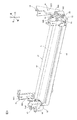
画像形成装置の一例としてのプリンタ1は、図1に示すように、電子写真方式のモノクロプリンタである。プリンタ1は、本体の一例としての、開口部6を有する本体ケーシング2と、プロセスカートリッジ3と、スキャナユニット4と、定着装置5とを備えている。   A printer 1 as an example of an image forming apparatus is an electrophotographic monochrome printer as shown in FIG. The printer 1 includes a main body casing 2 having an opening 6, a process cartridge 3, a scanner unit 4, and a fixing device 5 as an example of a main body.

本体ケーシング2は、略ボックス形状を有している。本体ケーシング2は、フロントカバー7と、給紙トレイ8と、排紙トレイ9とを備えている。   The main casing 2 has a substantially box shape. The main casing 2 includes a front cover 7, a paper feed tray 8, and a paper discharge tray 9.

開口部6は、本体ケーシング2の前端部に配置されている。開口部6は、プロセスカートリッジ3の通過を許容するように、本体ケーシング2の内外を前後方向に連通している。   The opening 6 is disposed at the front end of the main casing 2. The opening 6 communicates the inside and outside of the main casing 2 in the front-rear direction so as to allow passage of the process cartridge 3.

フロントカバー7は、本体ケーシング2の前端部に配置されている。フロントカバー7は、側面視略L字の板形状を有している。フロントカバー7は、その下端部を支点として本体ケーシング2の前壁に揺動可能に支持されている。フロントカバー7は、開口部6を開放または閉鎖するように構成されている。   The front cover 7 is disposed at the front end of the main casing 2. The front cover 7 has a substantially L-shaped plate shape in side view. The front cover 7 is swingably supported on the front wall of the main casing 2 with its lower end as a fulcrum. The front cover 7 is configured to open or close the opening 6.

給紙トレイ8は、本体ケーシング2の底部に配置されている。給紙トレイ8は、用紙Pを収容するように構成されている。   The paper feed tray 8 is disposed at the bottom of the main casing 2. The paper feed tray 8 is configured to accommodate the paper P.

排紙トレイ9は、本体ケーシング2の上壁に配置されている。排紙トレイ9は、用紙Pが載置されるように、本体ケーシング2の上面から下方へ凹んでいる。   The paper discharge tray 9 is disposed on the upper wall of the main body casing 2. The paper discharge tray 9 is recessed downward from the upper surface of the main casing 2 so that the paper P is placed thereon.

プロセスカートリッジ3は、本体ケーシング2の上下方向略中央部に収容されている。プロセスカートリッジ3は、開口部6を介して本体ケーシング2に対して装着または離脱するように構成されている。プロセスカートリッジ3は、ドラムカートリッジ10と、現像カートリッジ11とを備えている。   The process cartridge 3 is accommodated in a substantially central portion in the vertical direction of the main body casing 2. The process cartridge 3 is configured to be attached to or detached from the main casing 2 through the opening 6. The process cartridge 3 includes a drum cartridge 10 and a developing cartridge 11.

ドラムカートリッジ10は、感光ドラム12と、スコロトロン型帯電器13と、転写ローラ14とを備えている。   The drum cartridge 10 includes a photosensitive drum 12, a scorotron charger 13, and a transfer roller 14.

感光ドラム12は、ドラムカートリッジ10の後端部に回転可能に支持されている。感光ドラム12は、左右方向に延びる略円筒形状を有している。   The photosensitive drum 12 is rotatably supported at the rear end portion of the drum cartridge 10. The photosensitive drum 12 has a substantially cylindrical shape extending in the left-right direction.

スコロトロン型帯電器13は、感光ドラム12の後方において、感光ドラム12と間隔を隔てて配置されている。   The scorotron charger 13 is disposed behind the photosensitive drum 12 and spaced from the photosensitive drum 12.

転写ローラ14は、感光ドラム12の下方に配置されている。転写ローラ14は、感光ドラム12の下端部と接触している。   The transfer roller 14 is disposed below the photosensitive drum 12. The transfer roller 14 is in contact with the lower end portion of the photosensitive drum 12.

現像カートリッジ11は、感光ドラム12の前方において、ドラムカートリッジ10に装着されている。現像カートリッジ11は、現像ローラ15と、供給ローラ16と、層厚規制ブレード17と、トナー収容部18と、アジテータ19とを備えている。   The developing cartridge 11 is attached to the drum cartridge 10 in front of the photosensitive drum 12. The developing cartridge 11 includes a developing roller 15, a supply roller 16, a layer thickness regulating blade 17, a toner container 18, and an agitator 19.

現像ローラ15は、現像カートリッジ11の後端部に回転可能に支持されている。現像ローラ15は、左右方向に延びる略円柱形状を有している。現像ローラ15は、感光ドラム12の前端部に接触している。   The developing roller 15 is rotatably supported at the rear end portion of the developing cartridge 11. The developing roller 15 has a substantially cylindrical shape extending in the left-right direction. The developing roller 15 is in contact with the front end portion of the photosensitive drum 12.

供給ローラ16は、現像ローラ15の前下方に配置されている。供給ローラ16は、現像カートリッジ11に回転可能に支持されている。供給ローラ16は、左右方向に延びる略円柱形状を有している。供給ローラ16は、現像ローラ15の前下端部に接触している。   The supply roller 16 is disposed in front of and below the developing roller 15. The supply roller 16 is rotatably supported by the developing cartridge 11. The supply roller 16 has a substantially cylindrical shape extending in the left-right direction. The supply roller 16 is in contact with the front lower end portion of the developing roller 15.

層厚規制ブレード17は、現像ローラ15の前上方に配置されている。層厚規制ブレード17は、現像ローラ15の前端部に接触している。   The layer thickness regulating blade 17 is disposed on the front upper side of the developing roller 15. The layer thickness regulating blade 17 is in contact with the front end portion of the developing roller 15.

トナー収容部18は、供給ローラ16および層厚規制ブレード17の前方に配置されている。トナー収容部18は、トナーを収容するように構成されている。   The toner container 18 is disposed in front of the supply roller 16 and the layer thickness regulating blade 17. The toner storage unit 18 is configured to store toner.

アジテータ19は、トナー収容部18内において、回転可能に支持されている。   The agitator 19 is rotatably supported in the toner storage unit 18.

スキャナユニット4は、本体ケーシング2に収容されており、プロセスカートリッジ3の上方に配置されている。スキャナユニット4は、感光ドラム12に向けて画像データに基づくレーザービームを出射するように構成されている。   The scanner unit 4 is accommodated in the main casing 2 and is disposed above the process cartridge 3. The scanner unit 4 is configured to emit a laser beam based on image data toward the photosensitive drum 12.

定着装置5は、本体ケーシング2に収容されており、プロセスカートリッジ3の後方に間隔を隔てて配置されている。定着装置5は、ヒートユニット22と、回転体の一例としての加圧ローラ21とを備えている。   The fixing device 5 is accommodated in the main body casing 2 and is disposed behind the process cartridge 3 with a space therebetween. The fixing device 5 includes a heat unit 22 and a pressure roller 21 as an example of a rotating body.

ヒートユニット22は、定着装置5の上方部分に配置されている。   The heat unit 22 is disposed in the upper part of the fixing device 5.

加圧ローラ21は、ヒートユニット22の下方に配置されている。加圧ローラ21は、ヒートユニット22の下端部に接触している。   The pressure roller 21 is disposed below the heat unit 22. The pressure roller 21 is in contact with the lower end portion of the heat unit 22.

プリンタ1が画像形成動作を開始すると、スコロトロン型帯電器13は、感光ドラム12の表面を一様に帯電する。スキャナユニット4は、画像データに基づいて感光ドラム12の表面を露光する。これにより、画像データに基づく静電潜像が、感光ドラム12の表面に形成される。   When the printer 1 starts an image forming operation, the scorotron charger 13 uniformly charges the surface of the photosensitive drum 12. The scanner unit 4 exposes the surface of the photosensitive drum 12 based on the image data. As a result, an electrostatic latent image based on the image data is formed on the surface of the photosensitive drum 12.

また、アジテータ19は、トナー収容部18内のトナーを撹拌して、供給ローラ16に供給する。供給ローラ16は、アジテータ19によって供給されたトナーを現像ローラ15に供給する。このとき、トナーは、現像ローラ15と供給ローラ16との間で正極性に摩擦帯電され、現像ローラ15に担持される。層厚規制ブレード17は、現像ローラ15に担持されたトナーの層厚を一定厚さに規制する。   The agitator 19 agitates the toner in the toner storage unit 18 and supplies it to the supply roller 16. The supply roller 16 supplies the toner supplied from the agitator 19 to the developing roller 15. At this time, the toner is frictionally charged positively between the developing roller 15 and the supply roller 16 and is carried on the developing roller 15. The layer thickness regulating blade 17 regulates the layer thickness of the toner carried on the developing roller 15 to a constant thickness.

そして、現像ローラ15に担持されたトナーは、感光ドラム12表面の静電潜像に供給される。これにより、トナー像が、感光ドラム12の表面に担持される。   The toner carried on the developing roller 15 is supplied to the electrostatic latent image on the surface of the photosensitive drum 12. As a result, the toner image is carried on the surface of the photosensitive drum 12.

用紙Pは、給紙トレイ8から、各種ローラの回転により、所定のタイミングで1枚ずつ、感光ドラム12と転写ローラ14との間に給紙される。感光ドラム12表面のトナー像は、用紙Pが感光ドラム12と転写ローラ14との間を通過するときに、用紙Pに転写される。   The paper P is fed from the paper feed tray 8 between the photosensitive drum 12 and the transfer roller 14 one by one at a predetermined timing by the rotation of various rollers. The toner image on the surface of the photosensitive drum 12 is transferred to the paper P when the paper P passes between the photosensitive drum 12 and the transfer roller 14.

次いで、用紙Pは、加圧ローラ21が回転することにより、加圧ローラ21とヒートユニット22との間に進入する。そして、ヒートユニット22および加圧ローラ21は、用紙Pがヒートユニット22と加圧ローラ21との間を通過するときに、用紙Pを加熱および加圧する。これにより、用紙P上のトナー像は、用紙Pに熱定着される。その後、用紙Pは、排紙トレイ9に配置される。   Next, the paper P enters between the pressure roller 21 and the heat unit 22 as the pressure roller 21 rotates. The heat unit 22 and the pressure roller 21 heat and press the paper P when the paper P passes between the heat unit 22 and the pressure roller 21. As a result, the toner image on the paper P is thermally fixed to the paper P. Thereafter, the paper P is placed on the paper discharge tray 9.

定着装置5は、図1および図2に示すように、定着フレーム31と、回転体の一例としての加圧ローラ21と、ヒートユニット22と、第1押圧ユニット80と、第2押圧ユニット90とを備えている。   As shown in FIGS. 1 and 2, the fixing device 5 includes a fixing frame 31, a pressure roller 21 as an example of a rotating body, a heat unit 22, a first pressing unit 80, and a second pressing unit 90. It has.

定着フレーム31は、図1に示すように、左右方向に延びる略ボックス形状を有している。定着フレーム31は、フレームの一例としての下フレーム39と、上フレーム38とを備えている。   As shown in FIG. 1, the fixing frame 31 has a substantially box shape extending in the left-right direction. The fixing frame 31 includes a lower frame 39 and an upper frame 38 as an example of a frame.

下フレーム39は、図2および図3に示すように、定着フレーム31の下部に配置されている。下フレーム39は、樹脂材料からなる。なお、下フレーム39は、ガラス繊維、金属、セラミックスなどの公知の添加物を含有することもできる。下フレーム39は、第1側壁41と、第2側壁42と、底壁43と、前壁44と、後壁(図示せず)とを一体に備えている。   As shown in FIGS. 2 and 3, the lower frame 39 is disposed below the fixing frame 31. The lower frame 39 is made of a resin material. The lower frame 39 can also contain known additives such as glass fibers, metals, and ceramics. The lower frame 39 integrally includes a first side wall 41, a second side wall 42, a bottom wall 43, a front wall 44, and a rear wall (not shown).

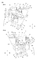
第1側壁41は、下フレーム39の右端部に配置されている。第1側壁41は、図4Aに示すように、第1受部の一例としての第1凹部50Aを有する第1側壁本体50と、定着側第1位置決め部の一例としての第1係合部51と、第2係合部52と、第1揺動ボス53と、第1接続部の一例としての第1接続軸54とを備えている。   The first side wall 41 is disposed at the right end of the lower frame 39. As shown in FIG. 4A, the first side wall 41 includes a first side wall body 50 having a first recess 50A as an example of a first receiving portion, and a first engagement portion 51 as an example of a fixing side first positioning portion. A second engagement portion 52, a first swing boss 53, and a first connection shaft 54 as an example of a first connection portion.

第1側壁本体50は、側面視略矩形の板形状を有している。第1凹部50Aは、第1側壁本体50の上端の前後方向中央部から下方に向かって凹んでいる。第1凹部50Aは、上方が開放された側面視略U字状を有している。第1凹部50Aの下端は、第1側壁本体50の上下方向中央部に位置している。   The first side wall main body 50 has a substantially rectangular plate shape in side view. The first recess 50 </ b> A is recessed downward from the front-rear direction center of the upper end of the first side wall body 50. The first recess 50A has a substantially U shape in a side view with its upper part opened. The lower end of the first recess 50 </ b> A is located at the center in the vertical direction of the first side wall body 50.

これにより、第1側壁本体50は、第1凹部50Aよりも前方に位置する前方部分50Bと、第1凹部50Aよりも後方に位置する後方部分50Cと、第1凹部50Aよりも下方に位置し、前方部分50Bの下端部および後方部分50Cの下端部と連続する下方部分50Dとに画定される。   Accordingly, the first side wall body 50 is positioned below the first recess 50A, the front portion 50B positioned in front of the first recess 50A, the rear portion 50C positioned rearward of the first recess 50A, and the first recess 50A. The lower portion 50D is defined by a lower end portion of the front portion 50B and a lower portion 50D continuous with the lower end portion of the rear portion 50C.

第1係合部51は、第1側壁本体50の右面において、前後方向に第1凹部50Aと並ぶように、第1凹部50Aに対して前方に間隔を空けて配置されている。これにより、第1係合部51は、第1側壁本体50の前方部分50Bの右面における上下方向略中央に配置されている。第1係合部51は、略角筒形状を有しており、第1側壁本体50の前方部分50Bから右方に向かって突出している。第1係合部51は、左右方向から見て、前上方と後下方とを結ぶ方向に延びている。つまり、第1係合部51は、前後方向と交差するように延びている。   The first engaging portion 51 is disposed on the right surface of the first side wall main body 50 with a space in the front from the first recess 50A so as to be aligned with the first recess 50A in the front-rear direction. As a result, the first engaging portion 51 is disposed substantially at the center in the vertical direction on the right surface of the front portion 50 </ b> B of the first side wall body 50. The first engaging portion 51 has a substantially rectangular tube shape and protrudes from the front portion 50 </ b> B of the first side wall body 50 toward the right. The first engaging portion 51 extends in a direction connecting the front upper side and the rear lower side as seen from the left-right direction. That is, the first engaging portion 51 extends so as to intersect the front-rear direction.

第2係合部52は、第1側壁本体50の右面において、第1係合部51の後下方に間隔を空けて配置されており、上下方向において第1凹部50Aと並ぶように、第1凹部50Aに対して下方に間隔を空けて配置されている。これにより、第2係合部52は、第1側壁本体50の下方部分50Dの右面の前後方向略中央に配置されている。第2係合部52は、略角筒形状を有しており、第1側壁本体50の下方部分50Dから右方に向かって突出している。第2係合部52は、左右方向に見たときに、前上方と後下方とを結ぶ方向に延びている。つまり、第2係合部52は、前後方向と交差するように延びている。   The second engaging portion 52 is disposed on the right surface of the first side wall body 50 with a space behind the first engaging portion 51 and spaced from the first engaging portion 51 in the vertical direction. It arrange | positions at intervals below the recessed part 50A. As a result, the second engaging portion 52 is disposed at the approximate center in the front-rear direction of the right surface of the lower portion 50D of the first side wall body 50. The second engaging portion 52 has a substantially rectangular tube shape and protrudes from the lower portion 50 </ b> D of the first side wall body 50 toward the right. The second engaging portion 52 extends in a direction connecting the front upper side and the rear lower side when viewed in the left-right direction. That is, the second engaging portion 52 extends so as to intersect the front-rear direction.

第1揺動ボス53は、第1側壁本体50の右面において、第2係合部52の後下方に間隔を空けて配置されている。第1揺動ボス53は、第1側壁本体50の下方部分50Dの右面における後端部に配置されている。第1揺動ボス53は、略角柱形状を有しており、第1側壁本体50の下方部分50Dから右方に向かって突出している。   The first swing boss 53 is disposed on the right surface of the first side wall body 50 with a space behind the second engaging portion 52. The first swing boss 53 is disposed at the rear end portion on the right surface of the lower portion 50 </ b> D of the first side wall body 50. The first swing boss 53 has a substantially prismatic shape and protrudes from the lower portion 50D of the first side wall body 50 toward the right.

第1接続軸54は、第1側壁本体50の左面において、前後方向に第1凹部50Aと並ぶように、第1凹部50Aに対して前方に間隔を空けて配置されている。これにより、第1接続軸54は、第1側壁本体50の前方部分50Bの左面における上端部に配置されている。つまり、第1接続軸54は、前後方向において、第1凹部50Aに対して、第1係合部51と同じ側である前方に位置している。また、第1接続軸54は、第1係合部51よりも上方に位置している。第1接続軸54は、略円柱形状を有しており、第1側壁本体50の前方部分50Bから左方に突出している。   The first connecting shaft 54 is disposed on the left surface of the first side wall main body 50 so as to be aligned with the first concave portion 50A in the front-rear direction with a space therebetween in front of the first concave portion 50A. Accordingly, the first connection shaft 54 is disposed at the upper end portion on the left surface of the front portion 50 </ b> B of the first side wall body 50. In other words, the first connecting shaft 54 is located in front of the first concave portion 50 </ b> A on the same side as the first engaging portion 51 in the front-rear direction. Further, the first connection shaft 54 is positioned above the first engagement portion 51. The first connecting shaft 54 has a substantially cylindrical shape and protrudes leftward from the front portion 50 </ b> B of the first side wall body 50.

第2側壁42は、図2および図3に示すように、下フレーム39の左端部に配置されている。第2側壁42は、図3および図4Bに示すように、第2受部の一例としての第2凹部55Aを有する第2側壁本体55と、定着側第2位置決め部の一例としての第3係合部56と、第4係合部57と、第2揺動ボス58と、第2接続部の一例としての第2接続軸59とを備えている。   The second side wall 42 is disposed at the left end portion of the lower frame 39 as shown in FIGS. 2 and 3. As shown in FIGS. 3 and 4B, the second side wall 42 includes a second side wall body 55 having a second recess 55A as an example of a second receiving portion, and a third relationship as an example of a fixing-side second positioning portion. The joint part 56, the 4th engaging part 57, the 2nd rocking | fluctuation boss | hub 58, and the 2nd connection shaft 59 as an example of a 2nd connection part are provided.

第2側壁本体55は、側面視略矩形の板形状を有している。第2凹部55Aは、第2側壁本体55の上端の前後方向中央部から下方に向かって凹んでいる。第2凹部55Aは、上方が開放された側面視略U字状を有している。第2凹部55Aの下端は、第2側壁本体55の上下方向中央部に位置している。また、第2凹部55Aは、左右方向から見て、第1凹部50Aと一致する。つまり、第2凹部55Aの前後方向の寸法は、第1凹部50Aの前後方向の寸法と同じである。   The second side wall main body 55 has a substantially rectangular plate shape in side view. The second recessed portion 55 </ b> A is recessed downward from the center portion in the front-rear direction of the upper end of the second side wall main body 55. The second recess 55 </ b> A has a substantially U shape in a side view with its upper part opened. The lower end of the second recess 55 </ b> A is located at the center in the vertical direction of the second side wall main body 55. Further, the second recess 55A coincides with the first recess 50A when viewed from the left-right direction. That is, the dimension in the front-rear direction of the second recess 55A is the same as the dimension in the front-rear direction of the first recess 50A.

これにより、第2側壁本体55は、第2凹部55Aよりも前方に位置する前方部分55Bと、第2凹部55Aよりも後方に位置する後方部分55Cと、第2凹部55Aよりも下方に位置し、前方部分55Bの下端部および後方部分55Cの下端部と連続する下方部分55Dとに画定される。   As a result, the second side wall body 55 is positioned below the front portion 55B positioned forward of the second recess 55A, the rear portion 55C positioned rearward of the second recess 55A, and below the second recess 55A. The lower portion 55D is defined by a lower end portion of the front portion 55B and a lower portion 55D continuous with the lower end portion of the rear portion 55C.

第3係合部56は、図4Bに示すように、第2側壁本体55の左面において、前後方向に第2凹部55Aと並ぶように、第2凹部55Aに対して前方に間隔を空けて配置されている。これにより、第3係合部56は、第2側壁本体55の前方部分55Bの左面における上下方向略中央に配置されている。第3係合部56は、略角筒形状を有しており、第2側壁本体55の前方部分55Bから左方に向かって突出している。第3係合部56は、左右方向から見て、前上方と後下方とを結ぶ方向に延びている。つまり、第3係合部56は、前後方向と交差するように延びている。   As shown in FIG. 4B, the third engagement portion 56 is disposed on the left surface of the second side wall main body 55 so as to be aligned with the second recess 55 </ b> A in the front-rear direction at a distance from the second recess 55 </ b> A. Has been. As a result, the third engaging portion 56 is disposed substantially at the center in the vertical direction on the left surface of the front portion 55 </ b> B of the second side wall body 55. The third engaging portion 56 has a substantially rectangular tube shape and protrudes leftward from the front portion 55B of the second side wall main body 55. The third engaging portion 56 extends in a direction connecting the front upper side and the rear lower side when viewed from the left-right direction. That is, the third engaging portion 56 extends so as to intersect the front-rear direction.

そして、第3係合部56は、図3に示すように、左右方向から見て、第1係合部51と重なるように配置されており、第1係合部51および第3係合部56は、左右方向に延びる同一の仮想直線L上に位置している。   As shown in FIG. 3, the third engagement portion 56 is disposed so as to overlap the first engagement portion 51 when viewed from the left-right direction, and the first engagement portion 51 and the third engagement portion 56 is located on the same virtual straight line L extending in the left-right direction.

第4係合部57は、図4Bに示すように、第2側壁本体55の左面において、第3係合部56の後下方に間隔を空けて配置されており、上下方向において第2凹部55Aと並ぶように、第2凹部55Aに対して下方に間隔を空けて配置されている。これにより、第4係合部57は、第2側壁本体55の下方部分55Dの左面における前後方向略中央に配置されている。第4係合部57は、略角筒形状を有しており、第2側壁本体55の下方部分55Dから左方に向かって突出している。第4係合部57は、左右方向に見たときに、前上方と後下方とを結ぶ方向に延びている。つまり、第4係合部57は、前後方向と交差するように延びている。   As shown in FIG. 4B, the fourth engagement portion 57 is disposed on the left surface of the second side wall main body 55 with a space behind the third engagement portion 56, and in the vertical direction, the second recess 55A. So as to be aligned with the second recess 55A so as to be spaced downward. As a result, the fourth engaging portion 57 is disposed at the approximate center in the front-rear direction on the left surface of the lower portion 55D of the second side wall body 55. The fourth engaging portion 57 has a substantially rectangular tube shape and protrudes leftward from the lower portion 55D of the second side wall main body 55. The fourth engaging portion 57 extends in a direction connecting the front upper side and the rear lower side when viewed in the left-right direction. That is, the fourth engaging portion 57 extends so as to intersect the front-rear direction.

第2揺動ボス58は、第2側壁本体55の左面において、第4係合部57の後下方に間隔を空けて配置されている。第2揺動ボス58は、第2側壁本体55の下方部分55Dの左面における後端部に配置されている。第2揺動ボス58は、略角柱形状を有しており、第2側壁本体55の下方部分55Dから左方に向かって突出している。第2揺動ボス58は、左右方向から見て、第1揺動ボス53と一致している。   The second swing boss 58 is disposed on the left surface of the second side wall body 55 with a space behind the fourth engagement portion 57. The second swing boss 58 is disposed at the rear end portion on the left surface of the lower portion 55 </ b> D of the second side wall body 55. The second swing boss 58 has a substantially prismatic shape, and protrudes from the lower portion 55 </ b> D of the second side wall body 55 toward the left. The second swing boss 58 is coincident with the first swing boss 53 when viewed from the left-right direction.

第2接続軸59は、第2側壁本体55の右面において、前後方向に第2凹部55Aと並ぶように、第2凹部55Aに対して前方に間隔を空けて配置されている。これにより、第2接続軸59は、第2側壁本体55の前方部分55Bの右面の上端部に配置されている。つまり、第2接続軸59は、前後方向において、第2凹部55Aに対して、第3係合部56と同じ側である前方に位置している。また、第2接続軸59は、第3係合部56よりも上方に位置しており、左右方向から見て、第1接続軸54と一致している。第2接続軸59は、略円柱形状を有しており、第2側壁本体55の前方部分55Bから右方に突出している。   The second connection shaft 59 is disposed on the right side of the second side wall main body 55 so as to be aligned with the second recess 55A in the front-rear direction with a space therebetween in front of the second recess 55A. Accordingly, the second connection shaft 59 is disposed at the upper end portion of the right surface of the front portion 55B of the second side wall body 55. In other words, the second connection shaft 59 is located in front of the second recess 55A on the same side as the third engagement portion 56 in the front-rear direction. The second connection shaft 59 is positioned above the third engagement portion 56 and coincides with the first connection shaft 54 when viewed from the left-right direction. The second connection shaft 59 has a substantially cylindrical shape and protrudes rightward from the front portion 55 </ b> B of the second side wall body 55.

底壁43は、図5Aに示すように、第1側壁41の下端部と、第2側壁42の下端部との間に架設されている。底壁43は、左右方方向に延びる底面視略矩形の板形状を有している。   As shown in FIG. 5A, the bottom wall 43 is constructed between the lower end portion of the first side wall 41 and the lower end portion of the second side wall 42. The bottom wall 43 has a substantially rectangular plate shape in bottom view extending in the left-right direction.

前壁44は、図3に示すように、第1側壁41の前下端部と、第2側壁の前下端部との間に架設されている。前壁44の下端部は、底壁43の前端部に接続されている。   As shown in FIG. 3, the front wall 44 is constructed between the front lower end portion of the first side wall 41 and the front lower end portion of the second side wall 41. The lower end portion of the front wall 44 is connected to the front end portion of the bottom wall 43.

後壁(図示せず)は、第1側壁41の後下端部と、第2側壁の後下端部との間に架設されている。後壁(図示せず)の下端部は、底壁43の後端部に接続されている。   The rear wall (not shown) is constructed between the rear lower end portion of the first side wall 41 and the rear lower end portion of the second side wall 41. The lower end of the rear wall (not shown) is connected to the rear end of the bottom wall 43.

上フレーム38は、図1に示すように、下方に向かって開放される略ボックス形状を有している。上フレーム38は、下フレーム39の上方に配置されている。   As shown in FIG. 1, the upper frame 38 has a substantially box shape that opens downward. The upper frame 38 is disposed above the lower frame 39.

加圧ローラ21は、図3および図4Bに示すように、シャフト61と、ローラ部62と、駆動伝達部の一例としての加圧ギア63とを備えている。   As illustrated in FIGS. 3 and 4B, the pressure roller 21 includes a shaft 61, a roller portion 62, and a pressure gear 63 as an example of a drive transmission portion.

シャフト61は、金属材料からなり、左右方向に延びる略円柱形状を有している。シャフト61の右端部は、第1側壁本体50の下方部分50Dに回転可能に支持されている。シャフト61の左端部は、第2側壁本体55の下方部分55Dに回転可能に支持されている。これによって、加圧ローラ21は、下フレーム39に回転可能に支持されている。また、シャフト61の左端部は、第2側壁本体55よりも左方に突出している。   The shaft 61 is made of a metal material and has a substantially cylindrical shape extending in the left-right direction. The right end portion of the shaft 61 is rotatably supported by the lower portion 50 </ b> D of the first side wall body 50. The left end portion of the shaft 61 is rotatably supported by the lower portion 55 </ b> D of the second side wall body 55. Thus, the pressure roller 21 is rotatably supported by the lower frame 39. Further, the left end portion of the shaft 61 protrudes leftward from the second side wall main body 55.

ローラ部62は、樹脂材料からなり、左右方向に延びる略円筒形状を有している。ローラ部62は、シャフト61の左右両端部を露出させるように、シャフト61の左右方向中央部分の周面を被覆している。そして、ローラ部62は、第1側壁41と第2側壁42との左右方向の間に配置されている。   The roller part 62 is made of a resin material and has a substantially cylindrical shape extending in the left-right direction. The roller portion 62 covers the peripheral surface of the central portion in the left-right direction of the shaft 61 so that both left and right end portions of the shaft 61 are exposed. The roller portion 62 is disposed between the first side wall 41 and the second side wall 42 in the left-right direction.

加圧ギア63は、左右方向に厚みを有する略円筒形状を有している。加圧ギア63は、その周面すべてにわたってギア歯を有している。加圧ギア63は、第2側壁42よりも左方に位置しており、シャフト61の左端部に相対回転不能に取り付けられている。   The pressure gear 63 has a substantially cylindrical shape having a thickness in the left-right direction. The pressure gear 63 has gear teeth over the entire peripheral surface thereof. The pressure gear 63 is located to the left of the second side wall 42 and is attached to the left end portion of the shaft 61 so as not to be relatively rotatable.

これにより、加圧ローラ21は、図4Bに示すように、加圧ギア63、シャフト61およびローラ部62が一体となって、左右方向に延びる回転軸線A1について回転するように構成されている。つまり、加圧ローラ21の長手方向と、加圧ローラ21の軸線方向とは、同一方向である。   As a result, as shown in FIG. 4B, the pressure roller 21 is configured such that the pressure gear 63, the shaft 61, and the roller portion 62 are integrated to rotate about the rotation axis A1 extending in the left-right direction. That is, the longitudinal direction of the pressure roller 21 and the axial direction of the pressure roller 21 are the same direction.

なお、加圧ギア63は、その前端部が、本体ケーシング2内に配置される駆動ギア66に噛み合っている。   Note that the front end of the pressure gear 63 meshes with a drive gear 66 disposed in the main body casing 2.

ヒートユニット22は、図2に示すように、加圧ローラ21の上方に配置されている。ヒートユニット22は、図1に示すように、ステイカバー71と、ステイ72と、反射板73と、ヒータ74と、加熱板75と、エンドレスベルト76とを備えている。   The heat unit 22 is disposed above the pressure roller 21 as shown in FIG. As shown in FIG. 1, the heat unit 22 includes a stay cover 71, a stay 72, a reflection plate 73, a heater 74, a heating plate 75, and an endless belt 76.

ステイカバー71は、耐熱性の樹脂材料からなり、左右方向に延びている。ステイカバー71は、下端部が開放される略ボックス形状を有している。ステイカバー71の前後方向の寸法は、第1凹部50Aの前後方向の寸法と略同じである。   The stay cover 71 is made of a heat-resistant resin material and extends in the left-right direction. The stay cover 71 has a substantially box shape whose lower end is opened. The longitudinal dimension of the stay cover 71 is substantially the same as the longitudinal dimension of the first recess 50A.

ステイ72は、ステイカバー71の内方に配置されている。ステイ72は、金属材料からなる。ステイ72は、左右方向に延びており、下端部が開放される略角筒形状を有している。   The stay 72 is disposed inside the stay cover 71. The stay 72 is made of a metal material. The stay 72 extends in the left-right direction and has a substantially rectangular tube shape with the lower end opened.

反射板73は、ステイ72の内方に配置されている。反射板73は、金属材料からなる。反射板73は、左右方向に延びており、下端部が開放される略角筒形状を有している。反射板73の内面は、鏡面加工されている。   The reflection plate 73 is disposed inside the stay 72. The reflection plate 73 is made of a metal material. The reflection plate 73 extends in the left-right direction, and has a substantially rectangular tube shape with the lower end opened. The inner surface of the reflecting plate 73 is mirror-finished.

ヒータ74は、反射板73の内方に配置されている。ヒータ74は、左右方向に延びる略円柱形状を有している。   The heater 74 is disposed inside the reflecting plate 73. The heater 74 has a substantially cylindrical shape extending in the left-right direction.

加熱板75は、ヒータ74の下方に配置されている。加熱板75は、金属材料からなる。加熱板75は、左右方向に延びる略板形状を有している。加熱板75は、ステイ72に支持されている。   The heating plate 75 is disposed below the heater 74. The heating plate 75 is made of a metal material. The heating plate 75 has a substantially plate shape extending in the left-right direction. The heating plate 75 is supported by the stay 72.

エンドレスベルト76は、耐熱性と可撓性とを有するフィルムであり、左右方向に延びる略円筒形状を有している。エンドレスベルト76の左右方向の寸法は、ステイカバー71の左右方向の寸法よりも小さい。そして、エンドレスベルト76は、その内周面が加熱板75の板状部75Aの下面に接触するように、ステイカバー71、ステイ72、反射板73、ヒータ74および加熱板75の周囲に巻かれている。   The endless belt 76 is a film having heat resistance and flexibility, and has a substantially cylindrical shape extending in the left-right direction. The lateral dimension of the endless belt 76 is smaller than the lateral dimension of the stay cover 71. The endless belt 76 is wound around the stay cover 71, the stay 72, the reflecting plate 73, the heater 74, and the heating plate 75 so that the inner peripheral surface thereof is in contact with the lower surface of the plate-like portion 75A of the heating plate 75. ing.

また、ステイカバー71の右端部は、エンドレスベルト76の右端部から右方に突出しており、ステイカバー71の左端部は、エンドレスベルト76の左端部から左方に突出している。   Further, the right end portion of the stay cover 71 protrudes rightward from the right end portion of the endless belt 76, and the left end portion of the stay cover 71 protrudes leftward from the left end portion of the endless belt 76.

このようなヒートユニット22は、図4Aおよび図4Bに示すように、ステイカバー71の右端部が、第1側壁本体50の第1凹部50Aに受け入れられ、ステイカバー71の左端部が、第2側壁本体55の第2凹部55Aに受け入れられることにより、下フレーム39に、上下方向にスライド移動可能な状態で支持されている。つまり、第1側壁本体50の第1凹部50Aは、ヒートユニット22の右端部を上下方向にスライド移動可能に受け入れ、第2側壁本体55の第2凹部55Aは、ヒートユニット22の左端部を上下方向にスライド移動可能に受け入れている。   As shown in FIGS. 4A and 4B, such a heat unit 22 has the right end portion of the stay cover 71 received in the first recess 50A of the first side wall body 50, and the left end portion of the stay cover 71 is the second end portion. By being received in the second recess 55 </ b> A of the side wall main body 55, it is supported on the lower frame 39 in a state in which it can slide in the vertical direction. That is, the first recess 50A of the first side wall body 50 receives the right end portion of the heat unit 22 so as to be slidable in the vertical direction, and the second recess 55A of the second side wall body 55 moves the left end portion of the heat unit 22 up and down. Accepts sliding movement in the direction.

これによって、ヒートユニット22は、加圧ローラ21と上下方向に向かい合っており、ヒートユニット22のエンドレスベルト76の下端部は、図1に示すように、加圧ローラ21の上端部に接触している。つまり、ヒートユニット22と加圧ローラ21とは互いに接触しており、接触部分Nを形成している。   As a result, the heat unit 22 faces the pressure roller 21 in the vertical direction, and the lower end portion of the endless belt 76 of the heat unit 22 contacts the upper end portion of the pressure roller 21 as shown in FIG. Yes. That is, the heat unit 22 and the pressure roller 21 are in contact with each other and form a contact portion N.

また、第1係合部51および第3係合部56は、図4Aおよび図4Bに示すように、接触部分Nよりも上方に位置している。つまり、第1係合部51および第3係合部56は、接触部分Nに対して、ヒートユニット22側に位置している。   Moreover, the 1st engaging part 51 and the 3rd engaging part 56 are located above the contact part N, as shown to FIG. 4A and 4B. That is, the first engagement portion 51 and the third engagement portion 56 are located on the heat unit 22 side with respect to the contact portion N.

第1押圧ユニット80は、図2に示すように、第1側壁41の上方に配置されている。第1押圧ユニット80は、図5Bに示すように、第1押圧部材の一例としての第1アーム81と、第1付勢部材82とを備えている。   As shown in FIG. 2, the first pressing unit 80 is disposed above the first side wall 41. As shown in FIG. 5B, the first pressing unit 80 includes a first arm 81 as an example of a first pressing member, and a first urging member 82.

第1アーム81は、金属材料からなり、凹部83Aを有するアーム本体83と、係止部84と、軸受部85と、押圧部86とを一体に備えている。   The first arm 81 is made of a metal material and integrally includes an arm main body 83 having a recess 83 </ b> A, a locking portion 84, a bearing portion 85, and a pressing portion 86.

アーム本体83は、前後方向に延びる側面視略矩形の板形状を有している。   The arm body 83 has a substantially rectangular plate shape in side view extending in the front-rear direction.

凹部83Aは、アーム本体83の後方部分に配置されている。凹部83Aは、下方に向かって開放される側面視略U字形状を有しており、アーム本体83の下端縁から上方に向かって凹んでいる。   The recess 83 </ b> A is disposed in the rear portion of the arm body 83. The recess 83 </ b> A has a substantially U shape in a side view opened downward, and is recessed upward from the lower end edge of the arm body 83.

係止部84は、凹部83A内に配置されている。係止部84は、側面視略L字形状を有しており、凹部83Aの前面から後方に向かって突出した後、上方に向かって屈曲している。   The locking portion 84 is disposed in the recess 83A. The locking portion 84 has a substantially L shape in side view, and protrudes rearward from the front surface of the recess 83A and then bends upward.

軸受部85は、第1アーム81の前端部であって、アーム本体83の前端部の下方に配置されている。軸受部85は、前方に向かって開放される側面視略C字形状を有している。そして、軸受部85の上端部がアーム本体83の前端部に接続されている。   The bearing portion 85 is a front end portion of the first arm 81 and is disposed below the front end portion of the arm main body 83. The bearing portion 85 has a substantially C-shape in side view that is opened toward the front. The upper end portion of the bearing portion 85 is connected to the front end portion of the arm main body 83.

押圧部86は、軸受部85と凹部83Aとの間に配置されている。押圧部86は、側面視略矩形形状を有しており、アーム本体83の下端から下方に向かって突出している。   The pressing portion 86 is disposed between the bearing portion 85 and the concave portion 83A. The pressing portion 86 has a substantially rectangular shape in side view, and protrudes downward from the lower end of the arm body 83.

そして、第1アーム81は、軸受部85が第1接続軸54を相対回転可能に受け入れることにより、第1接続軸54を支点として、第1側壁41に揺動可能に支持されている。つまり、第1接続軸54は、第1アーム81に接続されている。   The first arm 81 is swingably supported by the first side wall 41 with the first connecting shaft 54 as a fulcrum by the bearing portion 85 receiving the first connecting shaft 54 so as to be relatively rotatable. That is, the first connection shaft 54 is connected to the first arm 81.

また、第1アーム81は、押圧部86がステイカバー71の右端部に対して上方から接触するように、ヒートユニット22の上方に配置されている。つまり、第1アーム81は、ヒートユニット22に対して加圧ローラ21の反対側に配置されている。   The first arm 81 is disposed above the heat unit 22 so that the pressing portion 86 contacts the right end portion of the stay cover 71 from above. That is, the first arm 81 is disposed on the opposite side of the pressure roller 21 with respect to the heat unit 22.

第1付勢部材82は、上下方向に延びる引張りコイルばねであって、第1側壁41に対して左方に配置されている。第1付勢部材82は、その上端が、第1アーム81の係止部84に係止され、その下端が、第1側壁41の後下端部に係止されている。   The first biasing member 82 is a tension coil spring extending in the up-down direction, and is disposed on the left side with respect to the first side wall 41. The first urging member 82 has an upper end locked to the locking portion 84 of the first arm 81 and a lower end locked to the rear lower end of the first side wall 41.

これにより、第1アーム81は、常には、下方に向かう付勢力が付与されており、押圧部86によって、ステイカバー71の右端部を下方、すなわち、加圧ローラ21に向かって押圧している。   Thereby, the first arm 81 is always given a downward biasing force, and the pressing portion 86 presses the right end portion of the stay cover 71 downward, that is, toward the pressure roller 21. .

第2押圧ユニット90は、図2に示すように、第2側壁42の上方に配置されている。第2押圧ユニット90は、図4Bに示すように、第1押圧ユニット80と同様の構成を有しており、第2押圧部材の一例としての第2アーム91と、第2付勢部材92とを備えている。   The 2nd press unit 90 is arrange | positioned above the 2nd side wall 42, as shown in FIG. As shown in FIG. 4B, the second pressing unit 90 has the same configuration as the first pressing unit 80, and includes a second arm 91 as an example of a second pressing member, a second urging member 92, and the like. It has.

第2アーム91は、金属材料からなり、凹部93Aを有するアーム本体93と、係止部94と、軸受部95と、押圧部96とを一体に備えている。   The second arm 91 is made of a metal material, and integrally includes an arm main body 93 having a concave portion 93 </ b> A, a locking portion 94, a bearing portion 95, and a pressing portion 96.

アーム本体93は、前後方向に延びる側面視略矩形の板形状を有している。   The arm body 93 has a substantially rectangular plate shape in side view extending in the front-rear direction.

凹部93Aは、アーム本体93の後方部分に配置されている。凹部93Aは、下方に向かって開放される側面視略U字形状を有しており、アーム本体93の下端縁から上方に向かって凹んでいる。   The recessed portion 93 </ b> A is disposed in the rear portion of the arm main body 93. The concave portion 93 </ b> A has a substantially U shape in a side view opened downward, and is recessed upward from the lower end edge of the arm main body 93.

係止部94は、凹部93A内に配置されている。係止部94は、側面視略L字形状を有しており、凹部93Aの前面から後方に向かって突出した後、上方に向かって屈曲している。   The locking portion 94 is disposed in the recess 93A. The locking portion 94 has a substantially L shape in side view, and protrudes rearward from the front surface of the recess 93A and then bends upward.

軸受部95は、第1アーム81の前端部であって、アーム本体93の前端部の下方に配置されている。軸受部95は、前方に向かって開放される側面視略C字形状を有している。そして、軸受部95の上端部がアーム本体93の前端部に接続されている。   The bearing portion 95 is a front end portion of the first arm 81 and is disposed below the front end portion of the arm main body 93. The bearing portion 95 has a substantially C-shape in a side view opened toward the front. The upper end portion of the bearing portion 95 is connected to the front end portion of the arm main body 93.

押圧部96は、軸受部95と凹部93Aとの間に配置されている。押圧部96は、側面視略矩形形状を有しており、アーム本体93の下端から下方に向かって突出している。   The pressing portion 96 is disposed between the bearing portion 95 and the concave portion 93A. The pressing portion 96 has a substantially rectangular shape in side view, and protrudes downward from the lower end of the arm body 93.

そして、第2アーム91は、軸受部95が第2接続軸59を相対回転可能に受け入れることにより、第2接続軸59を支点として、第2側壁42に揺動可能に支持されている。つまり、第2接続軸59は、第2アーム91に接続されている。   The second arm 91 is swingably supported on the second side wall 42 with the second connecting shaft 59 as a fulcrum by the bearing portion 95 receiving the second connecting shaft 59 in a relatively rotatable manner. That is, the second connection shaft 59 is connected to the second arm 91.

また、第2アーム91は、押圧部96がステイカバー71の左端部に対して上方から接触するように、ヒートユニット22の上方に配置されている。つまり、第2アーム91は、ヒートユニット22に対して加圧ローラ21の反対側に配置されている。   The second arm 91 is disposed above the heat unit 22 so that the pressing portion 96 contacts the left end portion of the stay cover 71 from above. That is, the second arm 91 is disposed on the opposite side of the pressure roller 21 with respect to the heat unit 22.

第2付勢部材92は、上下方向に延びる引張りコイルばねであって、第2側壁42に対して右方に配置されている。第2付勢部材92は、その上端が、第2アーム91の係止部94に係止され、その下端が、第2側壁42の後下端部に係止されている。   The second urging member 92 is a tension coil spring extending in the vertical direction, and is disposed on the right side with respect to the second side wall 42. The upper end of the second urging member 92 is locked to the locking portion 94 of the second arm 91, and the lower end thereof is locked to the rear lower end portion of the second side wall 42.

これにより、第2アーム91は、常には、下方に向かう付勢力が付与されており、押圧部96によって、ステイカバー71の左端部を下方、すなわち、加圧ローラ21に向かって押圧している。   Accordingly, the second arm 91 is always given a downward biasing force, and the pressing portion 96 presses the left end portion of the stay cover 71 downward, that is, toward the pressure roller 21. .

本体ケーシング2は、図4Aおよび図4Bに示すように、本体側第1位置決め部の一例としての第1係合リブ103と、第2係合リブ104と、本体側第2位置決め部の一例としての第3係合リブ105と、第4係合リブ106とを備えている。   As shown in FIGS. 4A and 4B, the main body casing 2 includes a first engagement rib 103 as an example of the main body side first positioning portion, a second engagement rib 104, and an example of the main body side second positioning portion. The third engagement rib 105 and the fourth engagement rib 106 are provided.

第1係合リブ103および第2係合リブ104は、図4Aに示すように、本体ケーシング2の右側壁の左面に配置されている。   The first engagement rib 103 and the second engagement rib 104 are disposed on the left surface of the right side wall of the main casing 2 as shown in FIG. 4A.

第1係合リブ103は、定着装置5の第1係合部51に対応しており、上リブ103Aと、下リブ103Bとを備えている。   The first engagement rib 103 corresponds to the first engagement portion 51 of the fixing device 5 and includes an upper rib 103A and a lower rib 103B.

上リブ103Aは、本体ケーシング2の右側壁の左面から左方に突出している。上リブ103Aは、第1係合部51の上面の傾斜に沿っており、前上方と後下方とを結ぶ方向に延びる略板形状を有している。   The upper rib 103 </ b> A protrudes leftward from the left surface of the right side wall of the main body casing 2. The upper rib 103A has a substantially plate shape that extends along the inclination of the upper surface of the first engaging portion 51 and extends in a direction connecting the front upper side and the rear lower side.

下リブ103Bは、上リブ103Aと略平行となるように、上リブ103Aに対して前下方に間隔を空けて配置されている。上リブ103Aと下リブ103Bとの間の間隔は、第1係合部51の上下方向の寸法と略同じである。下リブ103Bは、本体ケーシング2の右側壁の左面から左方に突出している。下リブ103Bは、第1係合部51の下面の傾斜に沿っており、前上方と後下方とを結ぶ方向に延びる略板形状を有している。   The lower rib 103B is disposed at a front and lower interval with respect to the upper rib 103A so as to be substantially parallel to the upper rib 103A. The distance between the upper rib 103 </ b> A and the lower rib 103 </ b> B is substantially the same as the vertical dimension of the first engagement portion 51. The lower rib 103B protrudes leftward from the left surface of the right side wall of the main casing 2. The lower rib 103B has a substantially plate shape extending along the inclination of the lower surface of the first engagement portion 51 and extending in the direction connecting the front upper side and the rear lower side.

第2係合リブ104は、定着装置5の第2係合部52に対応している。第2係合リブ104は、下リブ103Bに対して後下方に間隔を空けて配置されている。第2係合リブ104は、本体ケーシング2の右側壁の左面から左方に突出している。第2係合リブ104は、第2係合部52の傾斜に沿っており、後下方に向かって開放される側面視略U字形状を有している。第2係合リブ104の上下方向の内寸は、第2係合部52の上下方向の寸法と略同じである。   The second engagement rib 104 corresponds to the second engagement portion 52 of the fixing device 5. The second engagement ribs 104 are arranged with a space rearward and downward with respect to the lower ribs 103B. The second engagement rib 104 protrudes leftward from the left surface of the right side wall of the main casing 2. The second engagement rib 104 has a substantially U shape in side view along the inclination of the second engagement portion 52 and is opened rearward and downward. The vertical dimension of the second engagement rib 104 is substantially the same as the vertical dimension of the second engagement part 52.

第3係合リブ105および第4係合リブ106は、図4Bに示すように、本体ケーシング2の左側壁の右面に配置されている。   The 3rd engagement rib 105 and the 4th engagement rib 106 are arrange | positioned at the right surface of the left side wall of the main body casing 2, as shown to FIG. 4B.

第3係合リブ105は、定着装置5の第3係合部56に対応しており、上リブ105Aと、下リブ105Bとを備えている。   The third engagement rib 105 corresponds to the third engagement portion 56 of the fixing device 5 and includes an upper rib 105A and a lower rib 105B.

上リブ105Aは、本体ケーシング2の左側壁の右面から右方に突出している。上リブ105Aは、第3係合部56の上面の傾斜に沿っており、前上方と後下方とを結ぶ方向に延びる略板形状を有している。   The upper rib 105A protrudes rightward from the right surface of the left side wall of the main casing 2. The upper rib 105A has a substantially plate shape that extends along the inclination of the upper surface of the third engagement portion 56 and extends in a direction connecting the front upper side and the rear lower side.

下リブ105Bは、上リブ105Aと略平行となるように、上リブ105Aに対して前下方に間隔を空けて配置されている。上リブ105Aと下リブ105Bとの間の間隔は、第3係合部56の上下方向の寸法と略同じである。下リブ105Bは、本体ケーシング2の左側壁の右面から右方に突出している。下リブ105Bは、第3係合部56の下面の傾斜に沿っており、前上方と後下方とを結ぶ方向に延びる略板形状を有している。   The lower rib 105B is disposed at a distance from the front and lower sides of the upper rib 105A so as to be substantially parallel to the upper rib 105A. The distance between the upper rib 105A and the lower rib 105B is substantially the same as the vertical dimension of the third engaging portion 56. The lower rib 105B protrudes rightward from the right surface of the left side wall of the main casing 2. The lower rib 105B is along the inclination of the lower surface of the 3rd engaging part 56, and has the substantially plate shape extended in the direction which connects a front upper direction and a rear lower direction.

第4係合リブ106は、定着装置5の第4係合部57に対応している。第4係合リブ106は、下リブ103Bに対して後下方に間隔を空けて配置されている。第4係合リブ106は、本体ケーシング2の左側壁の右面から右方に突出している。第4係合リブ106は、第4係合部57の傾斜に沿っており、後下方に向かって開放される側面視略U字形状を有している。第4係合リブ106の上下方向の内寸は、第4係合部57の上下方向の寸法と略同じである。   The fourth engagement rib 106 corresponds to the fourth engagement portion 57 of the fixing device 5. The fourth engagement ribs 106 are disposed at a rear lower side with respect to the lower rib 103B. The fourth engagement rib 106 protrudes rightward from the right surface of the left side wall of the main casing 2. The fourth engagement rib 106 has a substantially U shape in side view along the inclination of the fourth engagement portion 57 and opened rearward and downward. The vertical dimension of the fourth engagement rib 106 is substantially the same as the vertical dimension of the fourth engagement portion 57.

定着装置5は、本体ケーシング2に装着されて使用される。   The fixing device 5 is used by being mounted on the main casing 2.

詳しくは、定着装置5が本体ケーシング2に装着された状態において、第1側壁41の第1係合部51が、上リブ103Aおよび下リブ103Bの間に挟まれ、第2係合部52が、第2係合リブ104に後下方から嵌っている。また、第2側壁42の第3係合部56が、上リブ105Aおよび下リブ105Bの間に挟まれ、第4係合部57が、第4係合リブ106に後下方から嵌っている。   Specifically, in a state where the fixing device 5 is mounted on the main casing 2, the first engagement portion 51 of the first side wall 41 is sandwiched between the upper rib 103 </ b> A and the lower rib 103 </ b> B, and the second engagement portion 52 is The second engagement rib 104 is fitted from the rear lower side. Further, the third engagement portion 56 of the second side wall 42 is sandwiched between the upper rib 105A and the lower rib 105B, and the fourth engagement portion 57 is fitted to the fourth engagement rib 106 from the lower rear side.

つまり、第1係合部51が、第1係合リブ103と係合して、第1係合リブ103に位置決めされ、第2係合部52が、第2係合リブ104と係合し、第2係合リブ104に位置決めされ、第3係合部56が、第3係合リブ105と係合し、第3係合リブ105に位置決めされ、第4係合部57が、第4係合リブ106と係合し、第4係合リブ106に位置決めされている。   That is, the first engagement portion 51 engages with the first engagement rib 103 and is positioned by the first engagement rib 103, and the second engagement portion 52 engages with the second engagement rib 104. , The second engagement rib 104 is positioned, the third engagement portion 56 is engaged with the third engagement rib 105, the third engagement rib 105 is positioned, and the fourth engagement portion 57 is fourth. It is engaged with the engagement rib 106 and positioned on the fourth engagement rib 106.

これによって、定着装置5は、本体ケーシング2に対して位置決めされている。   Accordingly, the fixing device 5 is positioned with respect to the main body casing 2.

また、定着装置5が本体ケーシング2に対して位置決めされた状態で、第1側壁41の第1揺動ボス53は、本体ケーシング2の図示しない溝部に嵌り、第2側壁42の第2揺動ボス58は、本体ケーシング2の図示しない溝部に嵌っている。   Further, in a state where the fixing device 5 is positioned with respect to the main body casing 2, the first swing boss 53 of the first side wall 41 fits into a groove portion (not shown) of the main body casing 2 and the second swing of the second side wall 42. The boss 58 is fitted in a groove portion (not shown) of the main body casing 2.

定着装置5では、上記した画像形成動作が開始されると、図4Bに示すように、駆動ギア66から加圧ギア63に駆動力が付与される。   In the fixing device 5, when the image forming operation described above is started, a driving force is applied from the driving gear 66 to the pressure gear 63 as shown in FIG. 4B.

これにより、加圧ギア63が、左側面視時反計回り方向である回転方向Rに回転し、加圧ローラ21が、図1に示すように、回転方向Rに回転する。   As a result, the pressure gear 63 rotates in the rotation direction R that is the counterclockwise direction when viewed from the left side, and the pressure roller 21 rotates in the rotation direction R as shown in FIG.

このとき、図4Bに示すように、加圧ギア63は、駆動ギア66のトルクにより、上方に向かう力F1を受ける。これにより、シャフト61に対して上方に向かう力F1が加わり、シャフト61を介して、下フレーム39に対して上方に向かう力F1が加わる。   At this time, as shown in FIG. 4B, the pressure gear 63 receives an upward force F <b> 1 due to the torque of the drive gear 66. Accordingly, an upward force F1 is applied to the shaft 61, and an upward force F1 is applied to the lower frame 39 via the shaft 61.

すると、定着装置5は、図4Aおよび図4Bに示すように、第1揺動ボス53および第2揺動ボス58を支点として、左右方向に沿う軸線A2を中心に揺動するように力が付与される。   Then, as shown in FIGS. 4A and 4B, the fixing device 5 has a force to swing about the axis A2 along the left-right direction with the first swing boss 53 and the second swing boss 58 as fulcrums. Is granted.

ここで、第1係合部51および第3係合部56は、前上方と後下方とを結ぶ方向に延びており、定着装置5の揺動方向Sと交差するように延びている。そして、第1係合部51が第1係合リブ103と係合し、第3係合部56が第3係合リブ105と係合しているので、第1係合部51および第3係合部56が、定着装置5が揺動しようとする力を確実に受ける。そのため、定着装置5が揺動することを抑制できる。   Here, the first engaging portion 51 and the third engaging portion 56 extend in a direction connecting the front upper side and the rear lower side, and extend so as to intersect the swinging direction S of the fixing device 5. Since the first engaging portion 51 is engaged with the first engaging rib 103 and the third engaging portion 56 is engaged with the third engaging rib 105, the first engaging portion 51 and the third engaging portion The engaging portion 56 reliably receives the force that the fixing device 5 tries to swing. Therefore, the fixing device 5 can be prevented from swinging.

また、加圧ローラ21が回転方向Rに回転すると、図1に示すように、加圧ローラ21の回転に伴って、ヒートユニット22のエンドレスベルト76が周回移動する。このとき、ヒートユニット22は、図4Aおよび図4Bに示すように、加圧ローラ21の回転方向Rの下流に向かう力F2、つまり、後方に向かう力F2を受ける。   When the pressure roller 21 rotates in the rotation direction R, as shown in FIG. 1, the endless belt 76 of the heat unit 22 rotates and rotates with the rotation of the pressure roller 21. At this time, as shown in FIGS. 4A and 4B, the heat unit 22 receives a force F <b> 2 going downstream in the rotation direction R of the pressure roller 21, that is, a force F <b> 2 going backward.

すると、図4Aに示すように、第1押圧ユニット80の第1アーム81は、ヒートユニット22を介して、後方に向かう力F2を受け、さらには、第1側壁41の第1接続軸54は、第1アーム81を介して、後方に向かう力F2を受ける。   Then, as shown in FIG. 4A, the first arm 81 of the first pressing unit 80 receives the force F2 directed rearward through the heat unit 22, and further, the first connecting shaft 54 of the first side wall 41 is The force F <b> 2 directed backward is received via the first arm 81.

これによって、第1側壁41の第1側壁本体50のうち、第1凹部50Aに対して前方に位置する前方部分50Bは、後方に向かう力F2を受ける。   As a result, in the first side wall main body 50 of the first side wall 41, the front portion 50B positioned forward with respect to the first recess 50A receives a force F2 directed rearward.

ここで、第1係合部51は、第1側壁本体50の前方部分50Bにおいて、ヒートユニット22と加圧ローラ21との接触部分Nよりも上方に配置され、かつ、第1凹部50Aに対して、回転方向Rの上流に位置している。また、第1係合部51は、前後方向に対して交差するように延びている。そのため、第1係合部51は後方に向かう力F2を確実に受ける。その結果、第1側壁本体50の前方部分50Bが、後方に向かって撓むように変形することを抑制できる。   Here, the first engagement portion 51 is disposed above the contact portion N between the heat unit 22 and the pressure roller 21 in the front portion 50B of the first side wall main body 50, and with respect to the first recess 50A. And located upstream in the rotational direction R. Moreover, the 1st engaging part 51 is extended so that it may cross | intersect with respect to the front-back direction. Therefore, the 1st engaging part 51 receives the force F2 which goes back reliably. As a result, it is possible to suppress the front portion 50B of the first side wall body 50 from being deformed so as to bend backward.

また、第3係合部56は、図4Bに示すように、第2側壁本体55の前方部分55Bにおいて、ヒートユニット22と加圧ローラ21との接触部分Nよりも上方に配置され、かつ、第2凹部55Aに対して、回転方向Rの上流に位置している。また、第3係合部56は、前後方向に対して交差するように延びている。そのため、第3係合部56は後方に向かう力F2を確実に受ける。その結果、第2側壁本体55の前方部分55Bが、後方に向かって撓むように変形することを抑制できる。   Further, as shown in FIG. 4B, the third engagement portion 56 is disposed above the contact portion N between the heat unit 22 and the pressure roller 21 in the front portion 55B of the second side wall body 55, and It is located upstream in the rotation direction R with respect to the second recess 55A. Moreover, the 3rd engaging part 56 is extended so that it may cross | intersect with respect to the front-back direction. For this reason, the third engagement portion 56 reliably receives the force F2 directed rearward. As a result, it is possible to suppress the front portion 55B of the second side wall body 55 from being deformed so as to bend backward.

(1)定着装置5では、図4Aおよび図4Bに示すように、第1係合部51が、前後方向において第1凹部50Aと並ぶように配置され、第3係合部56が、前後方向において第2凹部55Aと並ぶように配置されている。そして、定着装置5がプリンタ1に装着された状態において、第1係合部51を第1係合リブ103に位置決めでき、第3係合部56を第3係合リブ105に位置決めできる。   (1) In the fixing device 5, as shown in FIGS. 4A and 4B, the first engaging portion 51 is arranged so as to be aligned with the first recess 50A in the front-rear direction, and the third engaging portion 56 is formed in the front-rear direction. Are arranged so as to be aligned with the second recess 55A. In a state where the fixing device 5 is mounted on the printer 1, the first engagement portion 51 can be positioned on the first engagement rib 103, and the third engagement portion 56 can be positioned on the third engagement rib 105.

つまり、定着装置5がプリンタ1に装着された状態において、第1側壁41において第1凹部50Aと前後方向に並ぶ部分、および、第2側壁42において第2凹部55Aと前後方向に並ぶ部分が、本体ケーシング2に位置決めされる。   That is, when the fixing device 5 is mounted on the printer 1, a portion aligned with the first recess 50 </ b> A in the first side wall 41 in the front-rear direction and a portion aligned with the second recess 55 </ b> A in the second side wall 42 in the front-rear direction. Positioned on the main casing 2.

その結果、加圧ギア63に駆動力が入力されても、第1凹部50Aを備える第1側壁41、および、第2凹部55Aを備える第2側壁42が変形することを抑制でき、ひいては、下フレーム39が変形することを抑制できる。   As a result, even if a driving force is input to the pressure gear 63, the first side wall 41 including the first recess 50A and the second side wall 42 including the second recess 55A can be prevented from being deformed. Deformation of the frame 39 can be suppressed.

(2)第1アーム81は、図4Aおよび図4Bに示すように、ヒートユニット22に対して加圧ローラ21の反対側に配置され、かつ、第1側壁41に支持されている。第2アーム91は、ヒートユニット22に対して加圧ローラ21の反対側に配置され、かつ、第2側壁42に支持されている。   (2) The first arm 81 is disposed on the opposite side of the pressure roller 21 with respect to the heat unit 22 and supported by the first side wall 41 as shown in FIGS. 4A and 4B. The second arm 91 is disposed on the opposite side of the pressure roller 21 with respect to the heat unit 22 and is supported by the second side wall 42.

そのため、第1アーム81および第2アーム91の効率的な配置を確保でき、第1アーム81および第2アーム91が、ヒートユニット22を加圧ローラ21に向かって確実に押圧できる。その結果、加圧ローラ21とヒートユニット22とを安定して接触させることができる。   Therefore, efficient arrangement of the first arm 81 and the second arm 91 can be ensured, and the first arm 81 and the second arm 91 can reliably press the heat unit 22 toward the pressure roller 21. As a result, the pressure roller 21 and the heat unit 22 can be stably brought into contact with each other.

また、第1係合部51は、接触部分Nに対してヒートユニット22側に位置している。そのため、第1係合部51を、第1側壁41の第1アーム81を支持する部分の近傍に配置することができる。その結果、第1側壁41の第1アーム81を支持する部分の近傍において、第1係合部51を第1係合リブ103に位置決めでき、第1側壁41が変形することを確実に抑制できる。   Further, the first engaging portion 51 is located on the heat unit 22 side with respect to the contact portion N. Therefore, the first engaging portion 51 can be disposed in the vicinity of the portion of the first side wall 41 that supports the first arm 81. As a result, in the vicinity of the portion of the first side wall 41 that supports the first arm 81, the first engagement portion 51 can be positioned on the first engagement rib 103, and the first side wall 41 can be reliably prevented from being deformed. .

また、第3係合部56は、接触部分Nに対してヒートユニット22側に位置している。そのため、第3係合部56を、第2側壁42の第2アーム91を支持する部分の近傍に配置することができる。その結果、第2側壁42の第2アーム91を支持する部分の近傍において、第3係合部56を第3係合リブ105に位置決めでき、第2側壁42が変形することを確実に抑制できる。   Further, the third engaging portion 56 is located on the heat unit 22 side with respect to the contact portion N. Therefore, the third engagement portion 56 can be disposed in the vicinity of the portion of the second side wall 42 that supports the second arm 91. As a result, the third engaging portion 56 can be positioned on the third engaging rib 105 in the vicinity of the portion of the second side wall 42 that supports the second arm 91, and deformation of the second side wall 42 can be reliably suppressed. .

(3)第1接続軸54は、図4Aおよび図4Bに示すように、前後方向において、第1凹部50Aに対して、第1係合部51と同じ側に配置されている。そのため、第1接続軸54と第1係合部51とを確実に近傍に配置できる。   (3) As shown in FIGS. 4A and 4B, the first connection shaft 54 is disposed on the same side as the first engagement portion 51 with respect to the first recess 50 </ b> A in the front-rear direction. Therefore, the first connection shaft 54 and the first engagement portion 51 can be reliably disposed in the vicinity.

また、第2接続軸59は、前後方向において、第2凹部55Aに対して、第3係合部56と同じ側に配置される。そのため、第2接続軸59と第3係合部56とを確実に近傍に配置できる。   The second connecting shaft 59 is disposed on the same side as the third engaging portion 56 with respect to the second recess 55A in the front-rear direction. Therefore, the second connection shaft 59 and the third engagement portion 56 can be reliably disposed in the vicinity.

(4)第1係合部51は、図4Aおよび図4Bに示すように、接触部分Nに対してヒートユニット22側に位置し、第1凹部50Aに対して回転方向Rの上流に位置している。そのため、第1アーム81を支持する第1側壁41が回転方向Rの下流に向かう力F2を受けても、第1側壁41が変形することをより一層確実に抑制できる。   (4) As shown in FIGS. 4A and 4B, the first engaging portion 51 is located on the heat unit 22 side with respect to the contact portion N, and is located upstream in the rotational direction R with respect to the first recess 50A. ing. Therefore, even if the first side wall 41 that supports the first arm 81 receives the force F <b> 2 that goes downstream in the rotation direction R, the first side wall 41 can be further reliably prevented from being deformed.

また、第3係合部56は、接触部分Nに対してヒートユニット22側に位置し、第2凹部55Aに対して回転方向Rの上流に位置している。そのため、第2アーム91を支持する第2側壁42が回転方向Rの下流に向かう力を受けても、第2側壁42が変形することをより一層確実に抑制できる。   Further, the third engagement portion 56 is located on the heat unit 22 side with respect to the contact portion N, and is located upstream of the rotation direction R with respect to the second recess 55A. Therefore, even if the second side wall 42 that supports the second arm 91 receives a force toward the downstream in the rotation direction R, it is possible to further reliably prevent the second side wall 42 from being deformed.

(5)第1係合部51および第3係合部56は、図3に示すように、左右方向に延びる同一の仮想直線L上に位置している。そのため、下フレーム39の左右方向両端部において、第1係合部51および第3係合部56を、上下方向および前後方向に互いに一致する位置で、本体ケーシング2に位置決めできる。その結果、下フレーム39がねじれるように変形することを抑制できる。   (5) As shown in FIG. 3, the first engaging portion 51 and the third engaging portion 56 are located on the same virtual straight line L extending in the left-right direction. Therefore, the first engagement portion 51 and the third engagement portion 56 can be positioned in the main casing 2 at positions that coincide with each other in the vertical direction and the front-rear direction at both ends in the left-right direction of the lower frame 39. As a result, the lower frame 39 can be prevented from being deformed so as to be twisted.

(6)第1係合部51および第3係合部56は、図4Aおよび図4Bに示すように、定着装置5の揺動方向Sと交差するように延びている。そのため、第1係合部51を第1係合リブ103に位置決めし、第3係合部56を第3係合リブ105に位置決めしたときに、定着装置5が揺動することを確実に抑制できる。   (6) The first engaging portion 51 and the third engaging portion 56 extend so as to intersect the swinging direction S of the fixing device 5 as shown in FIGS. 4A and 4B. Therefore, when the first engaging portion 51 is positioned on the first engaging rib 103 and the third engaging portion 56 is positioned on the third engaging rib 105, the fixing device 5 is reliably prevented from swinging. it can.

(7)第1係合部51および第3係合部56は、図4Aおよび図4Bに示すように、前後方向と交差するように延びている。そのため、第1側壁41および第2側壁42が前後方向に変形することを確実に抑制できる。   (7) As shown in FIGS. 4A and 4B, the first engaging portion 51 and the third engaging portion 56 extend so as to intersect with the front-rear direction. Therefore, it can suppress reliably that the 1st side wall 41 and the 2nd side wall 42 deform | transform in the front-back direction.

(8)プリンタ1において、図1に示すように、定着装置5は本体ケーシング2に収容されている。そのため、材料コストの低減および軽量化を図ることができながら、定着装置5の下フレーム39の変形を抑制できる。   (8) In the printer 1, as shown in FIG. 1, the fixing device 5 is accommodated in the main body casing 2. Therefore, the deformation of the lower frame 39 of the fixing device 5 can be suppressed while the material cost can be reduced and the weight can be reduced.

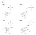
上記の実施形態では、図4Aおよび図4Bに示すように、第1係合リブ103が、本体側第1位置決め部に対応しているが、本体側第1位置決め部は、これに限定されず、図6Aおよび図6Cに示すように、第1係合溝110であってもよい。第1係合溝110は、本体ケーシング2の右側壁の左面から右方に凹む凹部である。   In the above embodiment, as shown in FIGS. 4A and 4B, the first engagement rib 103 corresponds to the main body side first positioning portion, but the main body side first positioning portion is not limited to this. 6A and 6C, the first engagement groove 110 may be used. The first engagement groove 110 is a recess that is recessed rightward from the left surface of the right side wall of the main casing 2.

第1係合溝110の形状は、第1係合部51を受け入れることができれば特に制限されない。例えば、第1係合溝110の上面および下面が、図6Aに示すように、互いに平行となるように、前上方と後下方とを結ぶ方向に延びていてもよい。また、第1係合溝110の上面が、図6Cに示すように、側面視クランク形状を有し、第1係合溝110の下面が、前上方と後下方とを結ぶ方向に延びていてもよい。   The shape of the first engagement groove 110 is not particularly limited as long as the first engagement portion 51 can be received. For example, as shown in FIG. 6A, the upper surface and the lower surface of the first engagement groove 110 may extend in a direction connecting the front upper side and the rear lower side so as to be parallel to each other. Further, as shown in FIG. 6C, the upper surface of the first engagement groove 110 has a crank shape in a side view, and the lower surface of the first engagement groove 110 extends in a direction connecting the front upper side and the rear lower side. Also good.

また、上記の実施形態では、図4Aおよび図4Bに示すように、第3係合リブ105が、本体側第2位置決め部に対応しているが、本体側第2位置決め部は、これに限定されず、図6Bおよび図6Dに示すように、第2係合溝111であってもよい。第2係合溝111は、本体ケーシング2の左側壁の右面から左方に凹む凹部である。   In the above embodiment, as shown in FIGS. 4A and 4B, the third engagement rib 105 corresponds to the main body side second positioning portion. However, the main body side second positioning portion is limited to this. Instead, as shown in FIGS. 6B and 6D, the second engagement groove 111 may be used. The second engagement groove 111 is a recess that is recessed leftward from the right surface of the left side wall of the main casing 2.

第2係合溝111の形状は、第3係合部56を受け入れることができれば特に制限されない。例えば、第2係合溝111の上面および下面が、図6Bに示すように、互いに平行となるように、前上方と後下方とを結ぶ方向に延びていてもよい。また、第2係合溝111の上面が、図6Dに示すように、側面視クランク形状を有し、第2係合溝111の下面が、前上方と後下方とを結ぶ方向に延びていてもよい。   The shape of the second engagement groove 111 is not particularly limited as long as the third engagement portion 56 can be received. For example, as shown in FIG. 6B, the upper surface and the lower surface of the second engagement groove 111 may extend in a direction connecting the front upper side and the rear lower side so as to be parallel to each other. Further, as shown in FIG. 6D, the upper surface of the second engagement groove 111 has a crank shape in a side view, and the lower surface of the second engagement groove 111 extends in a direction connecting the front upper side and the rear lower side. Also good.

つまり、第1係合部51が、凸部であり、第1係合溝110が、第1係合部51を受け入れる凹部であり、第3係合部56が、凸部であり、第2係合溝111が、第3係合部56を受け入れる凹部である。   That is, the first engaging portion 51 is a convex portion, the first engaging groove 110 is a concave portion that receives the first engaging portion 51, the third engaging portion 56 is a convex portion, and the second The engagement groove 111 is a recess that receives the third engagement portion 56.

これによっても、第1係合部51と第1係合溝110とを係合させることができ、第3係合部56と第2係合溝111とを係合させることができる。   Also by this, the 1st engaging part 51 and the 1st engaging groove 110 can be engaged, and the 3rd engaging part 56 and the 2nd engaging groove 111 can be engaged.

そのため、簡易な構成でありながら、第1係合部51を第1係合溝110に確実に位置決めでき、第3係合部56を第2係合溝111に確実に位置決めできる。その結果、第1側壁41および第2側壁42の変形を確実に抑制でき、ひいては、下フレーム39の変形を確実に抑制できる。つまり、このような変形例によっても、上記実施形態と同様の作用効果を奏することができる。   Therefore, the first engagement portion 51 can be reliably positioned in the first engagement groove 110 and the third engagement portion 56 can be reliably positioned in the second engagement groove 111 with a simple configuration. As a result, the deformation of the first side wall 41 and the second side wall 42 can be reliably suppressed, and as a result, the deformation of the lower frame 39 can be reliably suppressed. That is, also by such a modification, the same operation effect as the above-mentioned embodiment can be produced.

また、定着側第1位置決め部を凹部とし、本体側第1位置決め部を凸部とすることもでき、定着側第2位置決め部を凹部とし、本体側第2位置決め部を凸部とすることもできる。   Further, the fixing side first positioning portion can be a concave portion, the main body side first positioning portion can be a convex portion, the fixing side second positioning portion can be a concave portion, and the main body side second positioning portion can be a convex portion. it can.

なお、上記の実施形態および変形例は、適宜組み合わせることができる。   In addition, said embodiment and a modification can be combined suitably.

また、左右方向が長手方向の一例であり、上下方が直交方向の一例であり、前後方向が並び方向の一例である。   The left-right direction is an example of the longitudinal direction, the upper and lower directions are examples of the orthogonal direction, and the front-rear direction is an example of the arrangement direction.

1 プリンタ
2 本体ケーシング
5 定着装置
21 加圧ローラ
22 ヒートユニット
39 下フレーム
41 第1側壁
42 第2側壁
50A 第1凹部
51 第1係合部
54 第1接続軸
55A 第2凹部
56 第3係合部
59 第2接続軸
63 加圧ギア
81 第1アーム
91 第2アーム
110 第1係合溝
111 第2係合溝
L 仮想直線
N 接触部分
S 揺動方向
R 回転方向
DESCRIPTION OF SYMBOLS 1 Printer 2 Main body casing 5 Fixing device 21 Pressure roller 22 Heat unit 39 Lower frame 41 1st side wall 42 2nd side wall 50A 1st recessed part 51 1st engaging part 54 1st connection shaft 55A 2nd recessed part 56 3rd engagement Part 59 Second connection shaft 63 Pressure gear 81 First arm 91 Second arm 110 First engagement groove 111 Second engagement groove L Virtual straight line N Contact portion S Swing direction R Rotation direction

Claims (11)

本体側第1位置決め部および本体側第2位置決め部を有する本体を備える画像形成装置に装着可能な定着装置であって、
フレームと、
前記フレームに支持される回転体と、
前記回転体の長手方向における前記回転体の一端部に取り付けられる駆動伝達部と、
前記長手方向と直交する直交方向において、前記回転体と向かい合うヒートユニットと、を備え、
前記フレームは、
前記長手方向の一端部に位置し、前記回転体を支持する第1側壁と、
前記長手方向の他端部に位置し、前記回転体を支持する第2側壁と、を有し、
前記第1側壁は、
前記ヒートユニットの前記長手方向の一端部を、前記直交方向にスライド可能に受け入れる第1受部と、
前記長手方向および前記直交方向の両方向と直交する並び方向において、前記第1受部と並び、前記本体側第1位置決め部に位置決め可能な定着側第1位置決め部と、を備え、
前記第2側壁は、
前記ヒートユニットの前記長手方向の他端部を、前記直交方向にスライド可能に受け入れる第2受部と、
前記並び方向において、前記第2受部と並び、前記本体側第2位置決め部に位置決め可能な定着側第2位置決め部と、を備え
前記定着装置は、前記本体に装着され、前記回転体が回転したときに、前記長手方向に沿う軸線を中心に揺動するように力が付与され、
前記定着側第1位置決め部は、前記本体側第1位置決め部に対して、前記定着装置の揺動方向において接触可能であり、
前記定着側第2位置決め部は、前記本体側第2位置決め部に対して、前記揺動方向において接触可能であることを特徴とする、定着装置。
A fixing device attachable to an image forming apparatus including a main body having a main body side first positioning portion and a main body side second positioning portion,
Frame,
A rotating body supported by the frame;
A drive transmission unit attached to one end of the rotating body in the longitudinal direction of the rotating body;
A heat unit facing the rotating body in an orthogonal direction orthogonal to the longitudinal direction,
The frame is
A first side wall located at one end of the longitudinal direction and supporting the rotating body;
A second side wall located at the other end in the longitudinal direction and supporting the rotating body,
The first sidewall is
A first receiving portion for slidably receiving one end portion of the heat unit in the longitudinal direction in the orthogonal direction;
A fixing-side first positioning portion that is aligned with the first receiving portion and can be positioned on the main body-side first positioning portion in an alignment direction orthogonal to both the longitudinal direction and the orthogonal direction;
The second sidewall is
A second receiving portion that slidably receives the other end portion of the heat unit in the longitudinal direction in the orthogonal direction;
A fixing-side second positioning portion that is aligned with the second receiving portion and can be positioned on the main body-side second positioning portion in the alignment direction ;
The fixing device is attached to the main body, and when the rotating body rotates, a force is applied so as to swing around an axis along the longitudinal direction,
The fixing-side first positioning portion can contact the main-body-side first positioning portion in the swinging direction of the fixing device;
The fixing device, wherein the fixing-side second positioning portion can contact the main-body-side second positioning portion in the swing direction .
前記ヒートユニットに対して前記回転体の反対側に配置され、前記第1側壁に支持され、前記ヒートユニットの前記長手方向の一端部を前記回転体に向かって押圧する第1押圧部材と、
前記ヒートユニットに対して前記回転体の反対側に配置され、前記第2側壁に支持され、前記ヒートユニットの前記長手方向の他端部を前記回転体に向かって押圧する第2押圧部材と、をさらに備え、
前記回転体と前記ヒートユニットとは、互いに接触し、
前記定着側第1位置決め部は、前記回転体と前記ヒートユニットとの接触部分に対して前記ヒートユニット側に位置し、
前記定着側第2位置決め部は、前記接触部分に対して前記ヒートユニット側に位置していることを特徴とする、請求項1に記載の定着装置。
A first pressing member disposed on the opposite side of the rotating body with respect to the heat unit, supported by the first side wall, and pressing one end of the heat unit in the longitudinal direction toward the rotating body;
A second pressing member disposed on the opposite side of the rotating body with respect to the heat unit, supported by the second side wall, and pressing the other end of the heat unit in the longitudinal direction toward the rotating body; Further comprising
The rotating body and the heat unit are in contact with each other,
The fixing-side first positioning portion is located on the heat unit side with respect to a contact portion between the rotating body and the heat unit,
The fixing device according to claim 1, wherein the fixing-side second positioning portion is positioned on the heat unit side with respect to the contact portion.
前記第1側壁は、前記第1押圧部材に接続される第1接続部を有し、
前記第2側壁は、前記第2押圧部材に接続される第2接続部を有し、
前記第1接続部は、前記並び方向において、前記第1受部に対して、前記定着側第1位置決め部と同じ側に配置され、
前記第2接続部は、前記並び方向において、前記第2受部に対して、前記定着側第2位置決め部と同じ側に配置されることを特徴とする、請求項2に記載の定着装置。
The first side wall has a first connection portion connected to the first pressing member,
The second side wall has a second connection portion connected to the second pressing member,
The first connecting portion is arranged on the same side as the first fixing portion on the fixing side with respect to the first receiving portion in the arrangement direction.
3. The fixing device according to claim 2, wherein the second connecting portion is disposed on the same side as the fixing-side second positioning portion with respect to the second receiving portion in the arrangement direction.
前記定着側第1位置決め部は、前記第1受部に対して、前記回転体の回転方向の上流に位置し、
前記定着側第2位置決め部は、前記第2受部に対して、前記回転方向の上流に位置していることを特徴とする、請求項3に記載の定着装置。
The fixing-side first positioning portion is located upstream of the first receiving portion in the rotation direction of the rotating body,
4. The fixing device according to claim 3, wherein the fixing-side second positioning portion is located upstream of the second receiving portion in the rotation direction.
前記定着側第1位置決め部および前記定着側第2位置決め部は、前記長手方向に延びる同一の仮想直線上に位置していることを特徴とする、請求項1〜請求項4のいずれか一項に記載の定着装置。   5. The fixing side first positioning portion and the fixing side second positioning portion are located on the same imaginary straight line extending in the longitudinal direction. 6. The fixing device according to 1. 前記定着側第1位置決め部は、前記並び方向と交差するように延び、
前記定着側第2位置決め部は、前記並び方向と交差するように延びていることを特徴とする、請求項1〜請求項のいずれか一項に記載の定着装置。
The fixing-side first positioning portion extends so as to intersect the alignment direction,
The second positioning portion fixing-side is characterized by extending so as to intersect the alignment direction, the fixing device according to any one of claims 1 to 5.
前記第1側壁は、  The first sidewall is
前記直交方向において、前記回転体の回転軸線を挟んで前記定着側第1位置決め部の反対側に位置する定着側第3位置決め部をさらに備え、A fixing side third positioning portion located on the opposite side of the fixing side first positioning portion across the rotation axis of the rotating body in the orthogonal direction;
前記第2側壁は、  The second sidewall is
前記直交方向において、前記回転体の回転軸線を挟んで前記定着側第2位置決め部の反対側に位置する定着側第4位置決め部をさらに備えることを特徴とする、請求項1〜請求項6のいずれか一項に記載の定着装置。7. The fixing-side fourth positioning portion that is located on the opposite side of the fixing-side second positioning portion across the rotation axis of the rotating body in the orthogonal direction is further provided. The fixing device according to claim 1.
本体側第1位置決め部および本体側第2位置決め部を有する本体を備える画像形成装置に装着可能な定着装置であって、  A fixing device attachable to an image forming apparatus including a main body having a main body side first positioning portion and a main body side second positioning portion,
フレームと、  Frame,
前記フレームに支持される回転体と、  A rotating body supported by the frame;
前記回転体の長手方向における前記回転体の一端部に取り付けられる駆動伝達部と、  A drive transmission unit attached to one end of the rotating body in the longitudinal direction of the rotating body;
前記長手方向と直交する直交方向において、前記回転体と向かい合うヒートユニットと、を備え、  A heat unit facing the rotating body in an orthogonal direction orthogonal to the longitudinal direction,
前記フレームは、  The frame is
前記長手方向の一端部に位置し、前記回転体を支持する第1側壁と、    A first side wall located at one end of the longitudinal direction and supporting the rotating body;
前記長手方向の他端部に位置し、前記回転体を支持する第2側壁と、を有し、    A second side wall located at the other end in the longitudinal direction and supporting the rotating body,
前記第1側壁は、  The first sidewall is
前記ヒートユニットの前記長手方向の一端部を、前記直交方向にスライド可能に受け入れる第1受部と、    A first receiving portion for slidably receiving one end portion of the heat unit in the longitudinal direction in the orthogonal direction;
前記長手方向および前記直交方向の両方向と直交する並び方向において、前記第1受部と並び、前記本体側第1位置決め部に位置決め可能な定着側第1位置決め部と、    A fixing-side first positioning portion that is aligned with the first receiving portion and can be positioned on the main body-side first positioning portion in an alignment direction orthogonal to both the longitudinal direction and the orthogonal direction;
前記直交方向において、前記回転体の回転軸線を挟んで前記定着側第1位置決め部の反対側に位置する定着側第3位置決め部と、を備え、    A fixing-side third positioning portion located on the opposite side of the fixing-side first positioning portion across the rotation axis of the rotating body in the orthogonal direction;
前記第2側壁は、  The second sidewall is
前記ヒートユニットの前記長手方向の他端部を、前記直交方向にスライド可能に受け入れる第2受部と、    A second receiving portion that slidably receives the other end portion of the heat unit in the longitudinal direction in the orthogonal direction;
前記並び方向において、前記第2受部と並び、前記本体側第2位置決め部に位置決め可能な定着側第2位置決め部と、    A fixing-side second positioning portion that is aligned with the second receiving portion and can be positioned on the main-body-side second positioning portion in the alignment direction;
前記直交方向において、前記回転体の回転軸線を挟んで前記定着側第2位置決め部の反対側に位置する定着側第4位置決め部と、を備えることを特徴とする、定着装置。    A fixing device, comprising: a fixing-side fourth positioning portion positioned on the opposite side of the fixing-side second positioning portion across the rotation axis of the rotating body in the orthogonal direction.
前記駆動伝達部は、加圧ギアであり、前記画像形成装置が備える駆動ギアと噛み合い可能であり、The drive transmission unit is a pressure gear, and can mesh with a drive gear included in the image forming apparatus,
前記定着側第4位置決め部は、前記並び方向において、前記加圧ギアと前記駆動ギアとが噛み合う位置を挟んで、前記定着側第2位置決め部の反対側に位置することを特徴とする、請求項7または請求項8に記載の定着装置。The fixing-side fourth positioning portion is located on the opposite side of the fixing-side second positioning portion across the position where the pressure gear and the drive gear mesh with each other in the arrangement direction. The fixing device according to claim 7 or 8.
請求項1〜請求項のいずれか一項に記載の定着装置と、
前記定着装置を収容し、本体側第1位置決め部および本体側第2位置決め部を有する本体と、を備えることを特徴とする画像形成装置。
A fixing device according to any one of claims 1 to 9 ,
An image forming apparatus comprising: a main body that houses the fixing device and has a main body side first positioning portion and a main body side second positioning portion.
前記定着側第1位置決め部および前記本体側第1位置決め部のいずれか一方は、凸部であり、前記定着側第1位置決め部および前記本体側第1位置決め部のいずれか他方は、凸部を受け入れる凹部であり、
前記定着側第2位置決め部および前記本体側第2位置決め部のいずれか一方は、凸部であり、前記定着側第2位置決め部および前記本体側第2位置決め部のいずれか他方は、凸部を受け入れる凹部であることを特徴とする、請求項10に記載の画像形成装置。
One of the fixing side first positioning portion and the main body side first positioning portion is a convex portion, and one of the fixing side first positioning portion and the main body side first positioning portion is a convex portion. A recess to receive and
One of the fixing side second positioning portion and the main body side second positioning portion is a convex portion, and one of the fixing side second positioning portion and the main body side second positioning portion is a convex portion. The image forming apparatus according to claim 10 , wherein the image forming apparatus is a receiving recess.
JP2015086067A 2015-04-20 2015-04-20 Fixing apparatus and image forming apparatus Active JP6600977B2 (en)

Priority Applications (1)

Application Number Priority Date Filing Date Title
JP2015086067A JP6600977B2 (en) 2015-04-20 2015-04-20 Fixing apparatus and image forming apparatus

Applications Claiming Priority (1)

Application Number Priority Date Filing Date Title
JP2015086067A JP6600977B2 (en) 2015-04-20 2015-04-20 Fixing apparatus and image forming apparatus

Publications (2)

Publication Number Publication Date
JP2016206346A JP2016206346A (en) 2016-12-08
JP6600977B2 true JP6600977B2 (en) 2019-11-06

Family

ID=57489803

Family Applications (1)

Application Number Title Priority Date Filing Date
JP2015086067A Active JP6600977B2 (en) 2015-04-20 2015-04-20 Fixing apparatus and image forming apparatus

Country Status (1)

Country Link
JP (1) JP6600977B2 (en)

Family Cites Families (12)

* Cited by examiner, † Cited by third party
Publication number Priority date Publication date Assignee Title
JP3247012B2 (en) * 1994-04-27 2002-01-15 株式会社リコー Image forming device
JP3665982B2 (en) * 1997-12-19 2005-06-29 株式会社リコー Image recording device
JP3885487B2 (en) * 2000-11-20 2007-02-21 富士ゼロックス株式会社 Image forming apparatus
JP4280772B2 (en) * 2006-12-28 2009-06-17 キヤノン株式会社 Process cartridge and electrophotographic image forming apparatus
JP4980731B2 (en) * 2007-01-15 2012-07-18 京セラドキュメントソリューションズ株式会社 Toner container
JP5095019B2 (en) * 2012-03-09 2012-12-12 キヤノン株式会社 Process cartridge and electrophotographic image forming apparatus
JP2012133400A (en) * 2012-04-10 2012-07-12 Ricoh Co Ltd Fixing device and image forming apparatus
JP6157156B2 (en) * 2013-03-07 2017-07-05 キヤノン株式会社 Image heating device
EP2775357B1 (en) * 2013-03-07 2019-06-12 Canon Kabushiki Kaisha Image heating apparatus
JP6202833B2 (en) * 2013-03-07 2017-09-27 キヤノン株式会社 Pressurizing device and image heating device
US9354569B2 (en) * 2013-06-13 2016-05-31 Lexmark International, Inc. Heat transfer system for a fuser assembly
JP2015072337A (en) * 2013-10-02 2015-04-16 キヤノン株式会社 Image forming apparatus

Also Published As

Publication number Publication date
JP2016206346A (en) 2016-12-08

Similar Documents

Publication Publication Date Title
JP5263147B2 (en) Fixing device
JP6337792B2 (en) Developer cartridge
JP5263146B2 (en) Fixing device
JP6007596B2 (en) Image forming apparatus
JP5309541B2 (en) Fixing device
JP6164017B2 (en) Fixing device
JP6464784B2 (en) Image forming apparatus
JP6183270B2 (en) Photoconductor cartridge
JP6137026B2 (en) Image forming apparatus
JP6600977B2 (en) Fixing apparatus and image forming apparatus
JP5987282B2 (en) Process cartridge
JP5724678B2 (en) Image forming apparatus
JP6064867B2 (en) cartridge
JP6638207B2 (en) Fixing device
JP2017067955A (en) Fixation device
JP6693580B2 (en) Image forming device
WO2014010128A1 (en) Developing cartridge
JP6206454B2 (en) Fixing device
JP5772992B2 (en) Fixing device
JP5772996B2 (en) Fixing device
JP5884445B2 (en) Image forming apparatus and cartridge
JP2012194590A (en) Fixing device
JP6323008B2 (en) Photosensitive cartridge and process cartridge
JP6011085B2 (en) cartridge
JP2009069210A (en) Fixing device and image forming apparatus

Legal Events

Date Code Title Description
A621 Written request for application examination

Free format text: JAPANESE INTERMEDIATE CODE: A621

Effective date: 20180323

A977 Report on retrieval

Free format text: JAPANESE INTERMEDIATE CODE: A971007

Effective date: 20181226

A131 Notification of reasons for refusal

Free format text: JAPANESE INTERMEDIATE CODE: A131

Effective date: 20190108

A601 Written request for extension of time

Free format text: JAPANESE INTERMEDIATE CODE: A601

Effective date: 20190307

A521 Written amendment

Free format text: JAPANESE INTERMEDIATE CODE: A523

Effective date: 20190508

TRDD Decision of grant or rejection written
A01 Written decision to grant a patent or to grant a registration (utility model)

Free format text: JAPANESE INTERMEDIATE CODE: A01

Effective date: 20190910

A61 First payment of annual fees (during grant procedure)

Free format text: JAPANESE INTERMEDIATE CODE: A61

Effective date: 20190923

R150 Certificate of patent or registration of utility model

Ref document number: 6600977

Country of ref document: JP

Free format text: JAPANESE INTERMEDIATE CODE: R150