JP6598528B2 - Subject information acquisition apparatus and subject information acquisition method - Google Patents
Subject information acquisition apparatus and subject information acquisition method Download PDFInfo
- Publication number
- JP6598528B2 JP6598528B2 JP2015127704A JP2015127704A JP6598528B2 JP 6598528 B2 JP6598528 B2 JP 6598528B2 JP 2015127704 A JP2015127704 A JP 2015127704A JP 2015127704 A JP2015127704 A JP 2015127704A JP 6598528 B2 JP6598528 B2 JP 6598528B2
- Authority
- JP
- Japan
- Prior art keywords
- subject
- light
- conversion coefficient
- photoacoustic
- wavelength
- Prior art date
- Legal status (The legal status is an assumption and is not a legal conclusion. Google has not performed a legal analysis and makes no representation as to the accuracy of the status listed.)
- Active
Links
Images


Classifications
-
- A—HUMAN NECESSITIES
- A61—MEDICAL OR VETERINARY SCIENCE; HYGIENE
- A61B—DIAGNOSIS; SURGERY; IDENTIFICATION
- A61B5/00—Measuring for diagnostic purposes; Identification of persons
- A61B5/145—Measuring characteristics of blood in vivo, e.g. gas concentration or pH-value ; Measuring characteristics of body fluids or tissues, e.g. interstitial fluid or cerebral tissue
- A61B5/1455—Measuring characteristics of blood in vivo, e.g. gas concentration or pH-value ; Measuring characteristics of body fluids or tissues, e.g. interstitial fluid or cerebral tissue using optical sensors, e.g. spectral photometrical oximeters
- A61B5/14551—Measuring characteristics of blood in vivo, e.g. gas concentration or pH-value ; Measuring characteristics of body fluids or tissues, e.g. interstitial fluid or cerebral tissue using optical sensors, e.g. spectral photometrical oximeters for measuring blood gases
- A61B5/14552—Details of sensors specially adapted therefor
-
- A—HUMAN NECESSITIES
- A61—MEDICAL OR VETERINARY SCIENCE; HYGIENE
- A61B—DIAGNOSIS; SURGERY; IDENTIFICATION
- A61B5/00—Measuring for diagnostic purposes; Identification of persons
- A61B5/0093—Detecting, measuring or recording by applying one single type of energy and measuring its conversion into another type of energy
- A61B5/0095—Detecting, measuring or recording by applying one single type of energy and measuring its conversion into another type of energy by applying light and detecting acoustic waves, i.e. photoacoustic measurements
-
- A—HUMAN NECESSITIES
- A61—MEDICAL OR VETERINARY SCIENCE; HYGIENE
- A61B—DIAGNOSIS; SURGERY; IDENTIFICATION
- A61B5/00—Measuring for diagnostic purposes; Identification of persons
- A61B5/145—Measuring characteristics of blood in vivo, e.g. gas concentration or pH-value ; Measuring characteristics of body fluids or tissues, e.g. interstitial fluid or cerebral tissue
- A61B5/1455—Measuring characteristics of blood in vivo, e.g. gas concentration or pH-value ; Measuring characteristics of body fluids or tissues, e.g. interstitial fluid or cerebral tissue using optical sensors, e.g. spectral photometrical oximeters
- A61B5/14551—Measuring characteristics of blood in vivo, e.g. gas concentration or pH-value ; Measuring characteristics of body fluids or tissues, e.g. interstitial fluid or cerebral tissue using optical sensors, e.g. spectral photometrical oximeters for measuring blood gases
-
- A—HUMAN NECESSITIES
- A61—MEDICAL OR VETERINARY SCIENCE; HYGIENE
- A61B—DIAGNOSIS; SURGERY; IDENTIFICATION
- A61B5/00—Measuring for diagnostic purposes; Identification of persons
- A61B5/72—Signal processing specially adapted for physiological signals or for diagnostic purposes
- A61B5/7235—Details of waveform analysis
- A61B5/7246—Details of waveform analysis using correlation, e.g. template matching or determination of similarity
-
- A—HUMAN NECESSITIES
- A61—MEDICAL OR VETERINARY SCIENCE; HYGIENE
- A61B—DIAGNOSIS; SURGERY; IDENTIFICATION
- A61B5/00—Measuring for diagnostic purposes; Identification of persons
- A61B5/72—Signal processing specially adapted for physiological signals or for diagnostic purposes
- A61B5/7271—Specific aspects of physiological measurement analysis
- A61B5/7275—Determining trends in physiological measurement data; Predicting development of a medical condition based on physiological measurements, e.g. determining a risk factor
-
- A—HUMAN NECESSITIES
- A61—MEDICAL OR VETERINARY SCIENCE; HYGIENE
- A61B—DIAGNOSIS; SURGERY; IDENTIFICATION
- A61B5/00—Measuring for diagnostic purposes; Identification of persons
- A61B5/74—Details of notification to user or communication with user or patient; User input means
- A61B5/742—Details of notification to user or communication with user or patient; User input means using visual displays
Landscapes
- Health & Medical Sciences (AREA)
- Life Sciences & Earth Sciences (AREA)
- Physics & Mathematics (AREA)
- Engineering & Computer Science (AREA)
- Animal Behavior & Ethology (AREA)
- Veterinary Medicine (AREA)
- Biophysics (AREA)
- Biomedical Technology (AREA)
- Heart & Thoracic Surgery (AREA)
- Medical Informatics (AREA)
- Molecular Biology (AREA)
- Surgery (AREA)
- Pathology (AREA)
- General Health & Medical Sciences (AREA)
- Public Health (AREA)
- Artificial Intelligence (AREA)
- Computer Vision & Pattern Recognition (AREA)
- Physiology (AREA)
- Psychiatry (AREA)
- Signal Processing (AREA)
- Acoustics & Sound (AREA)
- Spectroscopy & Molecular Physics (AREA)
- Optics & Photonics (AREA)
- Ultra Sonic Daignosis Equipment (AREA)
- Measurement Of The Respiration, Hearing Ability, Form, And Blood Characteristics Of Living Organisms (AREA)
- Investigating Or Analyzing Materials By The Use Of Ultrasonic Waves (AREA)
Description
本発明は、被検体情報取得装置および被検体情報取得方法に関する。 The present invention relates to a subject information acquisition apparatus and a subject information acquisition method.
光を用いたイメージング技術の一つとして、光音響イメージング技術がある。光音響イメージングでは、まず、光源から発生したパルス光が被検体に照射される。照射光は被検体内で伝播・拡散し、被検体内の複数の箇所でこの光のエネルギーを吸収して音響波(以降、光音響波と呼ぶ)が発生する。この光音響波をトランスデューサで受信し、処理装置内で受信信号を解析処理することで、被検体内部の光学特性値に関する情報が画像データとして取得される。これにより、被検体内の光学特性値分布が可視化される。 One of imaging techniques using light is a photoacoustic imaging technique. In photoacoustic imaging, first, pulsed light generated from a light source is irradiated onto a subject. The irradiation light propagates and diffuses in the subject, and the energy of the light is absorbed at a plurality of locations in the subject to generate an acoustic wave (hereinafter referred to as a photoacoustic wave). The photoacoustic wave is received by the transducer, and the received signal is analyzed in the processing device, whereby information relating to the optical characteristic value inside the subject is acquired as image data. Thereby, the optical characteristic value distribution in the subject is visualized.
近年、光音響波を用いてより微細な光吸収体をイメージングするために、分解能の向上が求められている。そして、音を集束させたり、パルス光を集光させたりすることで、被検体表面付近の微細血管等の吸収体を高解像度でイメージングする、光音響顕微鏡の開発が進められている。 In recent years, in order to image finer light absorbers using photoacoustic waves, improvement in resolution has been demanded. Then, development of a photoacoustic microscope has been promoted that images an absorber such as a microvessel near the surface of a subject with high resolution by focusing sound or condensing pulsed light.
光吸収により被検体内の吸収体から発生する光音響波の初期音圧(P0)は次式(1)で表される。

ここで、Γはグリューナイセン係数であり、体積膨張係数(β)と音速(c)の二乗との積を定圧比熱(Cp)で除したものである。Φはある位置(局所的な領域)での光量である。この光量は、吸収体に照射された光量であり、光フルエンスとも呼ばれる。μaはある位置での光の吸収係数である。初期音圧(P0)は、光音響波を受信した探触子から出力される受信信号(PA信号:Photoacoustic信号)を用いて算出できる。
式(1)より、吸収係数μaを求めるためには、理論上、光量Φを取得する必要があることが理解される。
The initial sound pressure (P 0 ) of the photoacoustic wave generated from the absorber in the subject due to light absorption is expressed by the following equation (1).
Here, Γ is a Gruneisen coefficient, which is obtained by dividing the product of the volume expansion coefficient (β) and the square of the speed of sound (c) by the constant pressure specific heat (C p ). Φ is the amount of light at a certain position (local region). This amount of light is the amount of light irradiated to the absorber, and is also called light fluence. μ a is an absorption coefficient of light at a certain position. The initial sound pressure (P 0 ) can be calculated using a reception signal (PA signal: Photoacoustic signal) output from the probe that has received the photoacoustic wave.
From equation (1), in order to obtain the absorption coefficient mu a is theoretically it is understood that it is necessary to obtain the amount [Phi.
特許文献1の装置では、生体の形状と光照射分布とを測定し、これらの測定結果と生体内の平均的な光学係数に基づいて被検体内における光量Φの分布を計算している。
In the apparatus of
しかし、光音響顕微鏡を始めとする光音響装置において、被検体に照射される光の強度変化の影響や、受信信号の変化の影響を把握し、特性情報を精度よく取得することは簡単ではない場合がある。本発明は上記課題に鑑みてなされたものである。本発明の目的は、光を照射された被検体から発生する音響波を取得する装置において、簡易に被検体の特性情報を取得する方法を提供することにある。 However, in a photoacoustic apparatus such as a photoacoustic microscope, it is not easy to grasp the influence of the intensity change of the light irradiated on the subject and the influence of the change of the received signal and accurately acquire the characteristic information. There is a case. The present invention has been made in view of the above problems. An object of the present invention is to provide a method for easily acquiring characteristic information of a subject in an apparatus for acquiring an acoustic wave generated from the subject irradiated with light.
本発明は、以下の構成を採用する。すなわち、光が被検体に照射されることにより発生する音響波に由来する電気信号を用いて、前記被検体の特性情報を取得する被検体情報取得装置であって、
前記被検体の画像データを取得し、
前記被検体の前記画像データを用いて、前記被検体内部の吸収体の傾きに関する特徴量を取得する特徴量取得部と、
光照射によって発生する音響波の強度から光の吸収に関する係数への変換係数と、前記特徴量との関係を表すルックアップテーブルまたは関係式に基づいて、前記特徴量取得部により取得された前記特徴量に対応する前記変換係数を取得する変換係数取得部と、
前記電気信号および前記変換係数を用いて、前記被検体の前記特性情報を取得する信号処理部と、
を有することを特徴とする被検体情報取得装置である。
本発明はまた、以下の構成を採用する。すなわち、光が被検体に照射されることにより発生する音響波に由来する電気信号を用いて、前記被検体の特性情報を取得する被検体情報取得装置であって、
前記被検体の画像データを取得し、前記被検体の前記画像データを用いて、前記被検体内部の吸収体の深さ、太さ、および傾きに関する特徴量を取得する特徴量取得部と、
光照射によって発生する音響波の強度から光の吸収に関する係数への変換係数と、前記特徴量との関係を表すルックアップテーブルまたは関係式に基づいて、前記特徴量取得部により取得された前記特徴量に対応する前記変換係数を取得する変換係数取得部と、
前記電気信号および前記変換係数を用いて、前記被検体の前記特性情報を取得する信号
処理部と、
を有することを特徴とする被検体情報取得装置である。
The present invention employs the following configuration. That is, a subject information acquisition apparatus that acquires characteristic information of the subject using an electrical signal derived from an acoustic wave generated by irradiating the subject with light,
Obtaining image data of the subject;
Using the image data of the subject, a feature amount acquisition unit that acquires a feature amount related to the inclination of the absorber inside the subject;
The feature acquired by the feature amount acquisition unit based on a look-up table or a relational expression representing the relationship between the conversion coefficient from the intensity of the acoustic wave generated by light irradiation to a coefficient relating to light absorption and the feature amount. A conversion coefficient acquisition unit for acquiring the conversion coefficient corresponding to the quantity;
A signal processing unit that acquires the characteristic information of the subject using the electrical signal and the conversion coefficient;
A subject information acquisition apparatus characterized by comprising:
The present invention also employs the following configuration. That is, a subject information acquisition apparatus that acquires characteristic information of the subject using an electrical signal derived from an acoustic wave generated by irradiating the subject with light,
A feature amount acquisition unit that acquires image data of the subject, and uses the image data of the subject to acquire feature amounts relating to the depth, thickness, and inclination of the absorber inside the subject;
The feature acquired by the feature amount acquisition unit based on a look-up table or a relational expression representing the relationship between the conversion coefficient from the intensity of the acoustic wave generated by light irradiation to a coefficient relating to light absorption and the feature amount. A conversion coefficient acquisition unit for acquiring the conversion coefficient corresponding to the quantity;
A signal for acquiring the characteristic information of the subject using the electrical signal and the conversion coefficient
A processing unit;
A subject information acquisition apparatus characterized by comprising:
本発明はまた、以下の構成を採用する。すなわち、光が被検体に照射されることにより発生する音響波に由来する電気信号を用いて、前記被検体の特性情報を取得する被検体情報取得方法であって、
前記被検体の画像データを取得し、
前記被検体の前記画像データを用いて、前記被検体内部の吸収体の傾きに関する特徴量を取得し、
光照射によって発生する音響波の強度から光の吸収に関する係数への変換係数と、前記特徴量との関係を表すルックアップテーブルまたは関係式に基づいて、前記特徴量に対応する前記変換係数を取得し、
前記電気信号および前記変換係数を用いて、前記被検体の前記特性情報を取得する
ことを特徴とする被検体情報取得方法である。
The present invention also employs the following configuration. That is, a subject information acquisition method for acquiring characteristic information of the subject using an electrical signal derived from an acoustic wave generated by irradiating the subject with light,
Obtaining image data of the subject;
Using the image data of the subject, obtain a feature amount related to the inclination of the absorber inside the subject,
The conversion coefficient corresponding to the feature quantity is obtained based on a look-up table or a relational expression representing a relation between the conversion coefficient from the intensity of the acoustic wave generated by light irradiation to a coefficient relating to light absorption and the feature quantity. And
The object information acquiring method, wherein the characteristic information of the object is acquired using the electrical signal and the conversion coefficient.
本発明によれば、光を照射された被検体から発生する音響波を取得する装置において、簡易に被検体の特性情報を取得する方法を提供することができる。 ADVANTAGE OF THE INVENTION According to this invention, in the apparatus which acquires the acoustic wave generated from the subject irradiated with light, the method of acquiring the characteristic information of a subject easily can be provided.
以下に図面を参照しつつ、本発明の好適な実施の形態について説明する。ただし、以下に記載されている構成部品の寸法、材質、形状およびそれらの相対配置などは、発明が適用される装置の構成や各種条件により適宜変更されるべきものである。よって、この発明の範囲を以下の記載に限定する趣旨のものではない。 Hereinafter, preferred embodiments of the present invention will be described with reference to the drawings. However, the dimensions, materials, shapes, and relative arrangements of the components described below should be appropriately changed depending on the configuration of the apparatus to which the invention is applied and various conditions. Therefore, the scope of the present invention is not intended to be limited to the following description.
本発明は、被検体から伝播する音響波を検出し、被検体の特性情報を生成し、取得する技術に関する。よって本発明は、被検体情報取得装置またはその制御方法、あるいは被検
体情報取得方法や信号処理方法として捉えられる。本発明はまた、これらの方法をCPUやメモリ等のハードウェア資源を備える情報処理装置(コンピュータ)に実行させるプログラムや、そのプログラムを格納した記憶媒体としても捉えられる。
The present invention relates to a technology for detecting and transmitting acoustic waves propagating from a subject, generating characteristic information of the subject, and acquiring the same. Therefore, the present invention can be understood as a subject information acquisition apparatus or a control method thereof, a subject information acquisition method, or a signal processing method. The present invention can also be understood as a program for causing an information processing apparatus (computer) including hardware resources such as a CPU and a memory to execute these methods, and a storage medium storing the program.
本発明の被検体情報取得装置には、被検体に光(電磁波)を照射することにより被検体内で発生した音響波を受信して、被検体の特性情報を画像データとして取得する光音響効果を利用した装置を含む。本発明の特性情報とは、光音響波を受信することにより得られる受信信号を用いて生成される、被検体内の複数位置のそれぞれに対応する特性値の情報(特性値情報)である。 The subject information acquisition apparatus of the present invention receives an acoustic wave generated in a subject by irradiating the subject with light (electromagnetic waves), and acquires the subject's characteristic information as image data. Includes devices that use. The characteristic information of the present invention is characteristic value information (characteristic value information) corresponding to each of a plurality of positions in the subject, which is generated using a reception signal obtained by receiving a photoacoustic wave.
また本発明の被検体情報取得装置には、照射光と光音響波の少なくともいずれか一つをフォーカスする、光音響顕微鏡と呼ばれる装置を含む。このような装置においては、受信された光音響波に対して包絡線検波などの簡易な処理を行うだけで被検体の特性情報として利用できる場合がある。光音響顕微鏡装置や光音響トモグラフィー装置は、単に光音響装置とも呼ばれる。 The subject information acquisition apparatus of the present invention includes an apparatus called a photoacoustic microscope that focuses at least one of irradiation light and photoacoustic waves. In such an apparatus, there are cases where the received photoacoustic wave can be used as characteristic information of the subject simply by performing simple processing such as envelope detection. The photoacoustic microscope apparatus and the photoacoustic tomography apparatus are also simply referred to as a photoacoustic apparatus.
本発明でいう音響波とは、典型的には超音波であり、音波、音響波と呼ばれる弾性波を含む。探触子等により音響波から変換された電気信号を音響信号とも呼ぶ。ただし、本明細書における超音波または音響波という記載は、それらの弾性波の波長を限定する意図ではない。光音響効果により発生した音響波は、光音響波または光超音波と呼ばれる。光音響波に由来する電気信号を光音響信号とも呼ぶ。 The acoustic wave referred to in the present invention is typically an ultrasonic wave and includes an elastic wave called a sound wave or an acoustic wave. An electric signal converted from an acoustic wave by a probe or the like is also called an acoustic signal. However, the description of ultrasonic waves or acoustic waves in this specification is not intended to limit the wavelength of those elastic waves. An acoustic wave generated by the photoacoustic effect is called a photoacoustic wave or an optical ultrasonic wave. An electrical signal derived from a photoacoustic wave is also called a photoacoustic signal.
以下の実施形態における被検体情報取得装置は、例えば、人や動物の血管疾患などの診断や化学治療の経過観察などに利用できる。 The subject information acquisition apparatus in the following embodiments can be used for, for example, diagnosis of vascular diseases of humans and animals, follow-up of chemical treatment, and the like.
本発明により取得される特性情報は、光エネルギーの吸収率を反映した値である。例えば、光照射によって生じた音響波の発生源、被検体内の初期音圧、あるいは初期音圧から導かれる光エネルギー吸収密度や吸収係数、組織を構成する物質の濃度を含む。また、物質濃度としてオキシヘモグロビン濃度とデオキシヘモグロビン濃度を求めることにより、酸素飽和度分布を算出できる。また、グルコース濃度、コラーゲン濃度、メラニン濃度、脂肪や水の体積分率なども求められる。また、被検体内の各位置の特性情報に基づいて、2次元または3次元の特性情報分布が得られる。分布データは画像データとして生成され得る。 The characteristic information acquired by the present invention is a value reflecting the absorption rate of light energy. For example, a generation source of an acoustic wave generated by light irradiation, an initial sound pressure in a subject, a light energy absorption density or absorption coefficient derived from the initial sound pressure, and a concentration of a substance constituting a tissue are included. Further, the oxygen saturation distribution can be calculated by obtaining the oxyhemoglobin concentration and the deoxyhemoglobin concentration as the substance concentration. In addition, glucose concentration, collagen concentration, melanin concentration, fat and water volume fraction, and the like are also required. Further, a two-dimensional or three-dimensional characteristic information distribution is obtained based on the characteristic information at each position in the subject. The distribution data can be generated as image data.
互いに異なる波長を有する複数の光を照射することにより、被検体内に存在する物質の濃度に関する分布を取得できる。この場合、波長ごとに被検体内の吸収係数μaを求め、それらの値と求める物質固有の波長依存性とを用いて、物質の濃度に関する分布を画像化する。 By irradiating a plurality of lights having different wavelengths, a distribution relating to the concentration of the substance present in the subject can be acquired. In this case, the absorption coefficient μa in the subject is obtained for each wavelength, and the distribution relating to the concentration of the substance is imaged using these values and the wavelength dependence specific to the substance to be obtained.
特に、オキシヘモグロビンHbOとデオキシヘモグロビンHbとの濃度を基に、血液の酸素飽和度を取得できる。この際、各測定波長の光吸収分布データと、オキシヘモグロビンHbOとデオキシヘモグロビンHbの吸光度スペクトルとを用いて酸素飽和度を算出する。2波長を用いた場合、酸素飽和度SO2は次式(2)により求まる。
上式で、μa λ1は波長λ1における吸収係数、μa λ2は波長λ2における吸収係数を示す。また、εHb0 λ1は波長λ1におけるオキシヘモグロビンのモル吸光係数、εHb λ1は波長λ1におけるデオキシヘモグロビンのモル吸光係数を示す。εHb0 λ2は波長λ2におけるオキシヘモグロビンのモル吸光係数、εHb λ2は波長λ2におけるデオキシヘモグロビンのモル吸光係数を示す。εHb0 λ1、εHb λ1、εHb0 λ2、εHb λ2は既知の値である。なお、rは位置座標を示す。式(2)のように、2波長における吸収係数の比により血液の酸素飽和度を求めることができる。 In the above equation, μ a λ1 represents an absorption coefficient at wavelength λ 1 , and μ a λ2 represents an absorption coefficient at wavelength λ 2 . Ε Hb0 λ1 represents the molar extinction coefficient of oxyhemoglobin at the wavelength λ 1 , and ε Hb λ1 represents the molar extinction coefficient of deoxyhemoglobin at the wavelength λ1. ε Hb0 λ2 represents the molar extinction coefficient of oxyhemoglobin at the wavelength λ 2 , and ε Hb λ2 represents the molar extinction coefficient of deoxyhemoglobin at the wavelength λ 2 . ε Hb0 λ1 , ε Hb λ1 , ε Hb0 λ2 , and ε Hb λ2 are known values. Note that r indicates position coordinates. As in equation (2), the oxygen saturation of blood can be obtained from the ratio of absorption coefficients at two wavelengths.
式(1)より、2波長における吸収係数の比の値は以下のように表される。
すなわち、式(3)より、吸収係数の比の値を得るためには、理論上、波長λ1における光量Φλ1と波長λ2におけるΦλ2とを求める必要があることが理解される。
From Equation (1), the value of the ratio of absorption coefficients at two wavelengths is expressed as follows.
That is, the equation (3), in order to obtain the value of the ratio of the absorption coefficient, theoretically, it is understood that it is necessary to determine the [Phi .lambda.2 in light amount [Phi .lambda.1 and the wavelength lambda 2 at a wavelength lambda 1.
なお、3波長以上の光を用いた測定の場合、各測定波長の光吸収分布データを、オキシヘモグロビンとデオキシヘモグロビンの吸光度スペクトルを用いて、最小二乗法などによるフィッティングすることにより酸素飽和度等の濃度に関する情報を算出してもよい。この際においても、各波長における光量Φλを求める必要がある。 In the case of measurement using light of three or more wavelengths, the light absorption distribution data of each measurement wavelength is fitted using the absorbance spectrum of oxyhemoglobin and deoxyhemoglobin by the least square method, etc. Information on the concentration may be calculated. In this case also, it is necessary to obtain the light quantity Φ λ at each wavelength.
ここで、例えば装置が光音響顕微鏡である場合について詳しく説明する。光音響顕微鏡による測定領域は被検体表面近傍であるため、被検体に照射される励起光の被検体表面におけるビームプロファイルや照射位置がPA信号強度に大きく影響を与える。ここで、波長可変レーザー装置において、レーザー出射後の波長ごとのビームプロファイルの違いや、波長ごとの光の屈折率の違いにより、被検体表面における励起光のビームプロファイルや照射位置が波長ごとに異なる場合がある。このような場合、測定波長ごとのPA信号強度に影響が出る。 Here, for example, a case where the apparatus is a photoacoustic microscope will be described in detail. Since the measurement region by the photoacoustic microscope is in the vicinity of the subject surface, the beam profile and the irradiation position of the excitation light irradiated on the subject on the subject surface greatly affect the PA signal intensity. Here, in the wavelength tunable laser device, the beam profile of the excitation light and the irradiation position on the surface of the subject vary depending on the wavelength due to the difference in the beam profile for each wavelength after laser emission and the difference in the refractive index of the light for each wavelength. There is a case. In such a case, the PA signal intensity for each measurement wavelength is affected.
このため、例えば酸素飽和度の値を正確に求めるには、波長ごとのこれらの影響を考慮して吸収係数を求める必要がある。例えば2波長の場合、照射光量だけではなく、波長ごとにビームプロファイルや照射位置を測定する。そして、これらの光照射特性が光音響信号に与える影響を計算して補正することで、吸収係数の比を精度よく求められる。しかし、ビームプロファイルや照射位置を測定し、これらが光音響信号に与える影響を計算することは困難である場合がある。光照射の位置や精度の問題は、被検体の有無や、マッチング材の有無、それに伴う光の反射の程度に応じて変化する。このような場合、光プロファイルを用いた精度の光量Φの推定を行うことは困難である。例えば光フォーカスを行う場合、光学レンズ等を用いて光を集束させるため、被検体に照射される光のビームプロファ
イルを測定することは困難である。典型的には10μm以下のサイズの光のビームプロファイル測定は困難を伴う。また、1μm以下のサイズの光のビームプロファイル測定はさらに困難を伴う。
For this reason, for example, in order to accurately determine the value of oxygen saturation, it is necessary to determine the absorption coefficient in consideration of these effects for each wavelength. For example, in the case of two wavelengths, not only the amount of irradiation light but also the beam profile and irradiation position are measured for each wavelength. Then, by calculating and correcting the influence of these light irradiation characteristics on the photoacoustic signal, the ratio of the absorption coefficients can be obtained with high accuracy. However, it may be difficult to measure the beam profile or irradiation position and calculate the effect of these on the photoacoustic signal. The problem of the position and accuracy of light irradiation varies depending on the presence or absence of a subject, the presence or absence of a matching material, and the degree of light reflection associated therewith. In such a case, it is difficult to estimate the light quantity Φ with accuracy using the optical profile. For example, when optical focusing is performed, light is focused using an optical lens or the like, so that it is difficult to measure the beam profile of the light irradiated on the subject. Measurement of a beam profile of light having a size of typically 10 μm or less is difficult. Further, it is more difficult to measure the beam profile of light having a size of 1 μm or less.
[実施形態1]
以下、第1の実施形態の被検体情報取得装置の構成及び処理について説明する。なおこれ以降、同一の構成要素には原則として同一の符号を付して、説明を省略する。
[Embodiment 1]
The configuration and processing of the subject information acquisition apparatus according to the first embodiment will be described below. In the following, the same components are denoted by the same reference numerals in principle, and description thereof is omitted.
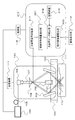
(全体的な装置構成)
図1は本実施形態の光音響装置の構成を示す模式図である。本実施形態の光音響装置は、光源100、光音響波を受信する変換素子101を備えるフォーカス型探触子102、および音響マッチング媒体103が満たされた容器104を備えている。
(Overall equipment configuration)
FIG. 1 is a schematic diagram showing the configuration of the photoacoustic apparatus of the present embodiment. The photoacoustic apparatus of the present embodiment includes a
光源100からの光は光導波部105により光出射部106に導かれ、光出射部106から出射される。なお、光源100からは、互いに異なる波長を有する複数のパルス光が別々のタイミングで出力される。酸素飽和度を求めるためには、波長の数は少なくとも、第1の波長と第2の波長の2つが必要である。光出射部106から出射された光107は、光学部材108および光学部材109により対象部位である光吸収体110近傍に集光されるように、被検体111に照射される。
Light from the
光吸収体110としては、典型的には生体内における血管、特に血管内に存在するヘモグロビン等の物質などがある。光吸収体110は、互いに異なる波長それぞれの光のエネルギーを吸収して、光音響波をそれぞれ発生する。発生した光音響波は、被検体内を伝搬し変換素子101に到達する。
The
変換素子101は、光音響波をフォーカスして受信することにより時系列の受信信号を出力する。変換素子101は音響波をフォーカスするような音響レンズを備えることが好ましい。出力された受信信号は、信号処理部112に入力される。信号処理部112には、照射されたパルス光によって生じる受信信号が順次入力される。
光音響装置はまた、探触子102や光出射部106等の測定部113を走査しながら測定するための走査機構114を備える。
The
The photoacoustic apparatus also includes a
光音響装置はまた、各構成ブロックを制御するための制御部115を備える。制御部115は各構成ブロックに必要な制御信号やデータを供給する。具体的には、光源100へ発光を指示する信号や、変換素子101の受信制御信号および走査機構114の制御信号を供給する。また、信号処理部112の信号増幅制御、AD変換タイミング制御、受信信号の記憶制御、被検体内の特性値情報の生成などを行う。
The photoacoustic apparatus also includes a
信号処理部112は、入力された各波長の受信信号と、吸収スペクトルが既知の標準サンプルを測定して求めた各波長の光音響信号と吸光度との変換係数を用いて、被検体111内の特性値情報を生成する。信号処理部112において生成された被検体内の特性値情報は、画像データとして画像表示部116に出力される。
The
(信号処理部の内部構成)
次に、本実施形態の信号処理部112内の構成を説明する。本実施形態の信号処理部112は、光音響信号収集部117、光音響データ補正部118、特性値情報算出部120を備える。
光音響信号収集部117は、変換素子101から出力される時系列のアナログ受信信号を収集し、受信信号の増幅や、アナログの受信信号のAD変換、デジタル化された受信信号の記憶等の信号処理を行う。例えば波長の数が2つであれば、第1の波長に由来する第
1の電気信号と、第2の波長に由来する第2の電気信号が得られる。
(Internal configuration of signal processor)
Next, the configuration within the
The photoacoustic
光音響データ補正部118は、光音響信号収集部117から出力される受信信号と、記憶装置119内に記憶されたルックアップテーブル中の変換係数を用いて、被検体111における光吸収体110の光吸収スペクトル情報を位置毎に取得する。変換係数は、各波長の光音響信号と吸光度との関係を示す。以下の実施形態において、光音響データ補正部は、本発明の変換係数取得部に相当する。従って、光源が第1の波長と第2の波長を照射する場合、少なくともそれぞれの波長に対応する第1の変換係数と第2の変換係数が存在する。
特性値情報算出部120は、光音響データ補正部118において求めた光吸収スペクトル分布情報から、被検体内の特性値情報を位置毎に取得する。光音響信号収集部および特性値情報算出部が行う処理は、本発明の信号処理部が行う処理に相当する。
The photoacoustic
The characteristic value
(信号処理部における処理)
本実施形態では、信号処理部112は、特性値情報として酸素飽和度を示す情報を少なくとも求める。ここで、「酸素飽和度」とは、本明細書における「濃度に関する情報」のうちの1つであり、赤血球中のヘモグロビンのうち、酸素と結合しているヘモグロビンの割合を示す。
(Processing in the signal processor)
In the present embodiment, the
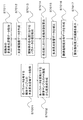
次に、信号処理部112が酸素飽和度分布を求める処理フローを図2を用いて説明する。
S2011のステップでは、複数の波長の光が異なるタイミングで被検体に照射される。これにより、光音響波が被検体内部から発生し、変換素子101に到達してアナログ受信信号に変化される。光音響信号収集部117は、測定波長ごとに変換素子101から出力される時系列のアナログ受信信号を収集し、受信信号の増幅や、アナログの受信信号のAD変換、デジタル化された受信信号の記憶等の信号処理を行う。なお、測定時は、走査機構114により、探触子102と光照射スポットとを被検体111に対して相対移動させて、複数の走査位置でアナログ受信信号を収集する。
Next, a processing flow in which the
In step S2011, the subject is irradiated with light having a plurality of wavelengths at different timings. Thereby, a photoacoustic wave is generated from the inside of the subject, reaches the
S2012のステップでは、光音響データ補正部118が、光音響信号収集部117から出力される受信信号と変換係数を用いて、被検体111における光吸収体110の光吸収スペクトル分布情報を取得する。
In the step of S2012, the photoacoustic
ここでいう変換係数とは、各波長における光音響信号と吸光度(または吸収係数)との変換係数のことである。変換係数は記憶装置119内にルックアップテーブルとして記憶されている。ルックアップテーブルは被検体111を測定する際に使用する波長における変換係数を有する。すなわち、記憶装置に保存されたルックアップテーブルは、光の波長と変換係数との関係を表すルックアップテーブルである。
The conversion coefficient here is a conversion coefficient between a photoacoustic signal and absorbance (or absorption coefficient) at each wavelength. The conversion coefficient is stored in the
また、被検体111を測定する際、ルックアップテーブルは事前に作成しておくことが好ましい。しかし、被検体111を測定した後に作成することも可能である。変換係数は、本実施形態の光音響装置を用いて、吸収スペクトルが既知の標準サンプルを、被検体111を測定する際に使用する波長において測定することで算出する(ステップS2001〜S2001)。 In addition, when measuring the subject 111, it is preferable to create a lookup table in advance. However, it can also be created after measuring the subject 111. The conversion coefficient is calculated by measuring a standard sample with a known absorption spectrum at the wavelength used when measuring the subject 111 using the photoacoustic apparatus of the present embodiment (steps S2001 to S2001).
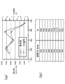
以下、光音響測定に先立って、予め変換係数を求め、ルックアップテーブルを作成する方法について、必要に応じて図8を参照しつつ説明する。変換係数αλiは以下の式で示される。添え字のλiは各測定波長を示す。
ここで、Cλiは標準サンプルの各波長における光の吸収を表わす係数であり、例えば吸光度や吸収係数などである。また、PAλiは測定した光音響信号を表し、各波長における標準サンプル測定時に光音響信号収集部117から出力される受信信号の信号強度を使用できる。受信信号の信号強度の表し方としては、光音響信号の最大値(PEAK値)、最大値と最小値の差(PEAK TO PEAK値)、包絡線検波後の最大値や積分値などが挙げられる。
Hereinafter, a method of obtaining a conversion coefficient in advance and creating a lookup table prior to photoacoustic measurement will be described with reference to FIG. 8 as necessary. The conversion coefficient α λi is expressed by the following equation. The subscript λ i indicates each measurement wavelength.
Here, C λi is a coefficient representing the absorption of light at each wavelength of the standard sample, such as absorbance or absorption coefficient. PA λi represents the measured photoacoustic signal, and the signal intensity of the received signal output from the photoacoustic
また、被検体111の測定波長が事前に決まっていない場合は、ルックアップテーブルは被検体111を測定する際に使用する可能性のある様々な波長における変換係数を有することが好ましい。その場合は、測定する可能性のある波長の近傍の波長域の様々な波長において測定し、各波長において変換係数を求めておく。 In addition, when the measurement wavelength of the subject 111 is not determined in advance, the lookup table preferably has conversion coefficients at various wavelengths that may be used when measuring the subject 111. In that case, measurement is performed at various wavelengths in the vicinity of the wavelength that may be measured, and a conversion coefficient is obtained at each wavelength.
図8(a)は、構成が既知の標準サンプルに対して複数の互いに異なる波長の光を照射したときの、吸光度およびPA信号強度をプロットしたグラフである。ここでの標準サンプルは、酸素飽和度が90%と判明している血液とする。図中、左側の縦軸は吸光度、右側の縦軸はPA信号強度、横軸は光の波長である。この値を元に式(4)の演算をすることにより、各波長における変換係数αが求まる。 FIG. 8A is a graph plotting absorbance and PA signal intensity when a plurality of lights having different wavelengths are irradiated onto a standard sample whose structure is known. The standard sample here is blood whose oxygen saturation is known to be 90%. In the figure, the left vertical axis represents absorbance, the right vertical axis represents PA signal intensity, and the horizontal axis represents light wavelength. Based on this value, the conversion coefficient α at each wavelength is obtained by calculating the equation (4).
図8(b)は、記憶部としての記憶装置に格納されるルックアップテーブルの一例である。ここでは、考慮するパラメータが波長のみである場合に、各波長における変換係数αを参照するためのテーブルを示している。なお、図8(a)のグラフや既知の光学特性などに基づいて、プロットされていない波長における変換係数を推定してもよい。また、ルックアップテーブルに変えて、またはルックアップテーブルとともに、吸光度とPA信号強度の変換式を求めても良い。 FIG. 8B is an example of a lookup table stored in a storage device as a storage unit. Here, a table for referring to the conversion coefficient α at each wavelength when the parameter to be considered is only the wavelength is shown. Note that conversion coefficients at wavelengths not plotted may be estimated based on the graph of FIG. 8A and known optical characteristics. Further, instead of the lookup table or together with the lookup table, a conversion formula between the absorbance and the PA signal intensity may be obtained.
標準サンプルは吸収スペクトルが既知のものを用いる。また、光吸収体110を模擬していることが好ましい。例えば、光吸収体110が血管であるならば、微細チューブ内に吸収スペクトルが既知の光吸収材料が入っているサンプルが好ましい。さらに、光吸収材料の凝集を防ぐために、光吸収材料が微細チューブ内を流れていることが好ましい。
A standard sample having a known absorption spectrum is used. Moreover, it is preferable to simulate the
光吸収材料としては、吸収係数が光吸収体110に近いものが好ましい、さらに、光散乱が光吸収体110に近いものが好ましい。このような光吸収材料として例えば、血液がある。使用する血液の吸収スペクトルを取得するために、使用する血液の酸素飽和度を予め測定しておき、オキシヘモグロビンとデオキシヘモグロビンの吸光度から吸収スペクトルを計算しておく必要がある。また、分光器などで測定して吸収スペクトルを計算しておいても良い。
As the light absorbing material, those having an absorption coefficient close to that of the
その他の光吸収材料としては、希釈した墨汁や色素溶液等を利用できる。また、光の散乱を付加するために、イントラリピッドや酸化チタンを用いると良い。
なお、標準サンプルは液体でなくても良い。例えば、ゲルに墨汁や色素等を混ぜたものをゲル化したサンプルを使用できる。このようなゲルとしてウレタンゲルがある。標準サンプルにはまた、寒天やゼラチンなども使用できる。
As other light-absorbing materials, diluted ink or pigment solution can be used. In order to add light scattering, intralipid or titanium oxide is preferably used.
The standard sample may not be liquid. For example, a sample obtained by gelling a mixture of ink, pigment, or the like with a gel can be used. An example of such a gel is urethane gel. Agar and gelatin can also be used as standard samples.
光音響データ補正部118は、記憶装置119のルックアップテーブルから各測定波長の変換係数を読み出す。そして次式のように、この変換係数と被検体111測定時に光音
響信号収集部117から出力される受信信号PAOBJ λiとの積をとることで、光吸収情報COBJ λiを求める。
このような計算により、各波長のビームプロファイルおよび光量などを補正できる。その結果、被検体111における光吸収体110の光吸収スペクトル情報を取得できる。この計算を測定位置ごとに行う事で、被検体111における光吸収体110の光吸収スペクトル分布情報が得られる。
The photoacoustic
By such calculation, the beam profile and light quantity of each wavelength can be corrected. As a result, the light absorption spectrum information of the
本実施形態では、各測定波長の変換係数は、記憶装置内に保存されたルックアップテーブルを参照して取得した。しかし、波長を変数とした変換式α(λ)を予め光音響データ補正部118に記憶しておき、変換計算により値を求めてもよい。変換式α(λ)は、光の波長と変換係数との関係を表す関係式である。すなわち、光音響データ補正部118は、光の波長と変換係数との関係を表す変換式α(λ)にしたがって、使用する光の波長に対応する変換係数を取得してもよい。
In the present embodiment, the conversion coefficient of each measurement wavelength is acquired with reference to a lookup table stored in the storage device. However, the conversion equation α (λ) with the wavelength as a variable may be stored in the photoacoustic
変換式α(λ)を算出する際には、まず、本実施形態の光音響装置を用いて吸収スペクトルが既知の標準サンプルを、測定に用いる可能性のある波長の近傍の様々な波長において測定する。そして、測定結果を式(4)に適用して変換係数を求める。そして、得られた様々な波長の変換係数を元に、最小二乗法等を用いて波長を変数とした変換式α(λ)を導出する。使用する標準サンプルはルックアップテーブルを作成した際と同様のもので良い。 When calculating the conversion equation α (λ), first, a standard sample with a known absorption spectrum is measured at various wavelengths in the vicinity of the wavelengths that may be used for measurement using the photoacoustic apparatus of the present embodiment. To do. Then, the conversion result is obtained by applying the measurement result to Equation (4). Then, based on the obtained conversion coefficients of various wavelengths, a conversion equation α (λ) with a wavelength as a variable is derived using a least square method or the like. The standard sample used may be the same as that used when creating the lookup table.
S2013のステップでは、特性値情報算出部120は、光音響データ補正部118において得られた光吸収体110の光吸収スペクトル分布情報を用いて、光吸収体110の酸素飽和度分布情報を取得する。
In step S2013, the characteristic value
例えば、測定波長が2波長の場合について説明する。この場合、光音響データ補正部118は、各位置における吸収体110の光吸収スペクトル情報として、COBJ λ1(r)とCOBJ λ2(r)の2つを取得する。ここで、rは光吸収情報COBJ λiにおけ
る時間軸方向を奥行き方向に変換して、空間座標上にプロットした際の空間座標を示している。そして、式(1)のμa λ1(r)とμa λ2(r)をCOBJ λ1(r)とCOBJ λ2(r)に置き換えた以下の式(6)により、各位置における酸素飽和度を計算する。
また、測定波長が3波長以上の場合は、光音響データ補正部118において得られた吸収体110の光吸収スペクトル情報とオキシヘモグロビンとデオキシヘモグロビンの光吸収スペクトルとを比較し、酸素飽和度を算出する。例えば、パラメータをオキシヘモグロビンとデオキシヘモグロビンの濃度とし、最小二乗法によるフィッティングなどを用いて酸素飽和度を算出する。また、光吸収体110にオキシヘモグロビンとデオキシヘモグロ
ビン以外の吸収体が含まれ、かつこれらの光吸収の影響が無視できない程大きい場合は、これらの吸収体の光吸収スペクトルも含めたフィッティングを行う事が好ましい。この際、フィッティングのパラメータはパラメータをオキシヘモグロビンとデオキシヘモグロビンの濃度およびこれらの吸収体の濃度となる。これらの吸収体として、例えばメラニン、脂肪、水、コラーゲンなどが考えられる。
When the measurement wavelength is 3 wavelengths or more, the light absorption spectrum information of the
また、特性値情報算出部120は、S2011で得られた受信信号を用いて、各測定波長のうち少なくとも1つの波長において音圧分布データを作成する。作成手法は例えば次の通りである。まず、得られた受信信号を時間変化に対して包絡線検波した後、光パルス毎の信号における時間軸方向を奥行き方向に変換して、空間座標上にプロットする。これを走査位置毎に行うことにより、音圧分布データを構成する。光音響顕微鏡ではこのような信号処理が一般的である。この処理方法であれば、受信信号を直接的にプロットできるので、演算の負荷や時間が軽減できる。ただし音圧を取得する際に、再構成の手法を用いてもよい。
Further, the characteristic value
S2014のステップでは、特性値情報算出部120によって作成された酸素飽和度分布データ及び音圧分布データを用いて、酸素飽和度分布画像を画像表示部116に表示する。表示手法として例えば、ボクセルごとに、酸素飽和度分布データから色度を、また音圧分布データから明度を決定して、この色度や明度を元に画像表示する方法がある。また、音圧強度が所定の閾値以上であるボクセルのみ、酸素飽和度分布データを表示するという手法も可能である。
In step S2014, an oxygen saturation distribution image is displayed on the
(信号処理部の具体的な構成例)
以降、詳細に本実施形態の信号処理部112内の各構成例を説明する。
光音響信号収集部117としては、一般的にDAS(Data Acquisition System)と呼ばれる回路を用いることができる。具体的には、光音響信号収集部117は、受信信号を増幅する増幅器、アナログの受信信号をデジタル化するAD変換器、受信信号を記憶するFIFO、RAM等のメモリ等を含む。
(Specific configuration example of signal processor)
Hereinafter, each configuration example in the
As the photoacoustic
光音響データ補正部118および特性値情報算出部120としては、CPUやGPU等のプロセッサ、FPGA(Field Programmable Gate Array)チップ等の演算回路を利用できる。なお、1つのプロセッサや演算回路から構成されるだけでなく、複数のプロセッサや演算回路から構成されていてもよい。
As the photoacoustic
また、光音響信号収集部117は受信信号を記憶するメモリを備えていてもよい。メモリは、典型的にはROM、RAM、およびハードディスクなどの記憶媒体から構成される。なお、メモリは、1つの記憶媒体から構成されるだけでなく、複数の記憶媒体から構成されていてもよい。
In addition, the photoacoustic
また、光音響データ補正部118および特性値情報算出部120は、変換係数のルックアップテーブル、受信信号、生成された分布データ、表示画像データ、各種測定パラメータ等を記憶する記憶装置119を参照可能である。記憶装置は、典型的には1つ以上のROM、RAM、およびハードディスクなどの記憶媒体から構成される。
Further, the photoacoustic
続いて、信号処理部112以外の構成についても具体的な構成例を説明する。
(光源100)
光源100は、ナノ秒からマイクロ秒オーダーのパルス光を発生可能なパルス光源が好ましい。具体的なパルス幅としては、1〜100ナノ秒程度のパルス幅が使われる。また、波長としては200nmから1600nm程度の範囲の波長が使われる。特に、本実施形態のように、生体表面近傍の血管を高解像度でイメージングする際は可視光領域を用い
ることが好ましい。ただし、テラヘルツ波、マイクロ波、ラジオ波領域の使用も可能である。
Next, a specific configuration example will be described for configurations other than the
(Light source 100)
The
具体的な光源100としてはレーザーが好ましい。特に、複数波長の光を用いて測定する際には、発振する波長の変換が可能なレーザーがより好ましい。ただし、複数波長を被検体111に照射できればよいため、互いに異なる波長の光を発振する複数台のレーザーを、それぞれ発振切り替えを行いながら、もしくは交互に照射しながら用いてもよい。複数台のレーザーを用いた場合もそれらをまとめて光源として表現する。
As the specific
レーザーとしては、固体レーザー、ガスレーザー、色素レーザー、半導体レーザーなど様々なレーザーを使用できる。特に、Nd:YAGレーザーやアレクサンドライトレーザーなどのパルスレーザーが好ましい。また、Nd:YAGレーザー光を励起光とするTi:saレーザーやOPO(Optical Parametric Oscillators)レーザーを用いてもよい。また、レーザーの代わりにフラッシュランプや発光ダイオードなどを用いてもよい。 As the laser, various lasers such as a solid laser, a gas laser, a dye laser, and a semiconductor laser can be used. In particular, a pulsed laser such as an Nd: YAG laser or an Alexandrite laser is preferable. Further, a Ti: sa laser or an OPO (Optical Parametric Oscillators) laser using Nd: YAG laser light as excitation light may be used. Further, a flash lamp or a light emitting diode may be used instead of the laser.
(光学系)
光源100から被検体111までは、光導波部105と光出射部106により光が伝達される。光導波部105及び光出射部106には、光学レンズ、ミラー、光ファイバ等の光学素子を使用できる。ただし、光源100から直接被検体に光照射しても良い。光学部材108としてはアキシコンミラー、光学部材109としては光学ミラー等がある。
例えば、光学系としては、被検体111に照射する光を10μm以下のサイズへと集束させる光学レンズを採用してもよい。光学系としては、また、被検体111に照射する光を1μm以下のサイズへと集束させる光学レンズを採用してもよい。
(Optical system)
Light is transmitted from the
For example, as the optical system, an optical lens that focuses the light applied to the subject 111 to a size of 10 μm or less may be employed. As the optical system, an optical lens that focuses light irradiated onto the subject 111 to a size of 1 μm or less may be employed.
(探触子102)
探触子102は1つ以上の変換素子101を備える。変換素子101としては、チタン酸ジルコン酸鉛(PZT)などの圧電現象を用いた圧電素子、光の共振を用いた変換素子、CMUT等の静電容量型の変換素子などがある。他にも、音響波を受信して電気信号に変換できれば、どのような変換素子を用いてもよい。複数の変換素子115を備える場合は、1Dアレイ、1.5Dアレイ、1.75Dアレイ、2Dアレイ、と呼ばれるような平面又は曲面内に並ぶように配置されることが好ましい。
(Probe 102)
The
光音響顕微鏡の場合は、探触子102はフォーカス型探触子とすることが好ましい。例えば変換素子101に音響レンズを備えることにより、音響波を収束させられる。また、探触子102内には、変換素子101から出力されるアナログ信号を増幅する増幅器を設けてもよい。
In the case of a photoacoustic microscope, the
また、探触子102の受信部は容器104中の音響マッチング媒体103に接触している必要がある。音響マッチング媒体としては、水やマッチングジェル等が使用できる。また、光音響波を透過させるために、容器104の底面はフィルムであることが好ましい。さらに、フィルムは光を吸収や散乱の小さいものを用いることが好ましい。
Further, the receiving unit of the
(表示部116)
表示部116は、LCD(Liquid Crystal Display)やCRT(Cathode Ray Tube)、有機ELディスプレイ等のディスプレイを利用できる。なお、表示部116は、本実施形態の光音響装置が備える構成とはせずに、別に用意して光音響装置に接続しても良い。
(Display 116)
The
[変形例]
上の記載では、フォーカス型探触子102を用いて音響波を絞ることで高い解像度を得る光音響顕微鏡について説明した。しかし、これ以外の光音響装置においても、本実施形態を用いることが可能である。図3に、本発明を、光をフォーカスして被検体に照射することにより解像度の高い光音響画像を取得する光音響顕微鏡に用いた際の構成例を示す。なお、測定部313に含まれる構成要素以外は図1と同様であるため、同一の符号を付して、詳しい説明を省略する。
[Modification]
In the above description, the photoacoustic microscope has been described that obtains a high resolution by narrowing the acoustic wave using the
光出射部306から出射された光303は光学レンズ317により、被検体内111の対象部位に集光される。光学レンズ317としては対物レンズが好ましい。光吸収体110が光のエネルギーを吸収すると、集光点から光音響波が発生する。発生した光音響波は、被検体内を伝搬し変換素子301に到達する。その後の処理フローについては、前述した音響フォーカス型と同様に実行できる。
The light 303 emitted from the
この構成を用いて測定することで、被検体111内の特性値情報をより高解像度に取得できる。その際も、上述したような、被検体に照射される波長ごとのビームプロファイルや光量などの影響を補正が可能である。その結果、本変形例においても、簡便にかつ精度よく酸素飽和度等の特性値情報を求めるという本発明の効果を享受できる。 By measuring using this configuration, the characteristic value information in the subject 111 can be acquired with higher resolution. Even in this case, it is possible to correct the influence of the beam profile and the amount of light for each wavelength irradiated on the subject as described above. As a result, also in this modification, it is possible to enjoy the effect of the present invention of obtaining characteristic value information such as oxygen saturation simply and accurately.
[実施形態2]
本発明の実施形態2における被検体情報取得装置の構成及び処理について説明する。
図4は本実施形態の光音響装置の構成を示す模式図である。なお、信号処理部412に含まれる構成要素以外は図1と共通しているので、同一の符号を付して詳しい説明を省略する。
[Embodiment 2]
The configuration and processing of the subject information acquisition apparatus according to the second embodiment of the present invention will be described.
FIG. 4 is a schematic diagram showing the configuration of the photoacoustic apparatus of the present embodiment. Since components other than those included in the
(信号処理部の内部構成)
本実施形態の信号処理部412内の構成を説明する。本実施形態の信号処理部412は、光音響信号収集部417、光音響データ補正部418、特性値情報算出部420および被検体特徴量抽出部421を備える。
(Internal configuration of signal processor)
The configuration within the
光音響信号収集部417は、変換素子101から出力される時系列のアナログ受信信号を収集し、受信信号の増幅や、アナログの受信信号のAD変換、デジタル化された受信信号の記憶等の信号処理を行う。
被検体特徴量抽出部421は、光音響信号収集部417から出力される受信信号を用いて、音圧分布データを作成し、作成した音圧分布データから各位置における被検体特徴量を抽出する。被検体特徴量抽出部は、本発明の特徴量取得部に相当する。
The photoacoustic
The subject feature
光音響データ補正部418は、光音響信号収集部417から出力される受信信号、被検体特徴量抽出部421において抽出された被検体特徴量、および、変換係数を用いて、被検体111における光吸収体110の光吸収スペクトル情報を位置毎に取得する。変換係数は、記憶装置419に格納されたルックアップテーブルとして存在する、各波長の光音響信号と吸光度との換算式である。 特性値情報算出部420は光音響データ補正部418において求めた光吸収スペクトル分布情報から、被検体内の特性値情報を位置毎に取得する。
The photoacoustic
(信号処理部における処理)
次に、信号処理部412が酸素飽和度分布を求める処理フローを、図5を用いて説明する。S5011のステップでは、複数の波長の光が異なるタイミングで照射されたのち、光音響信号収集部417は、測定波長ごとに変換素子101から出力される時系列のアナログ受信信号を収集する。そして、受信信号の増幅や、アナログの受信信号のAD変換、デジタル化された受信信号の記憶等の信号処理を行う。測定時は、走査機構114により
、探触子102と光照射スポットとを被検体111に対して相対移動させて、複数の走査位置でアナログ受信信号を収集する。
(Processing in the signal processor)
Next, a processing flow in which the
S5012のステップでは、被検体特徴量抽出部421は、光音響信号収集部417から出力される受信信号を用いて、光音響画像データ(以降、音圧分布データと呼ぶ)を作成する。音圧分布データは、各測定波長のうち少なくとも1つの波長において作成する。作成手法の一例を説明する。まず、得られた受信信号を時間変化に対して包絡線検波した後、光パルス毎の信号における時間軸方向を奥行き方向に変換して、空間座標上にプロットする。これを走査位置ごとに行うことにより、音圧分布データを構成する。
In step S5012, the subject feature
S5013のステップでは、被検体特徴量抽出部421は、作成した音圧分布データから被検体特徴量を抽出する。被検体特徴量とは、各位置における吸収体110の各パラメータの値である。パラメータとして、被検体111の各位置における吸収体110の太さ、角度(走査方向の法線方向に対しての角度)、形状、および被検体表面からの深さなどが挙げられる。例えば、被検体111のある位置には、太さ100μmの血管が、表面から深さが3mmの位置に、角度40度で存在する、というように各パラメータを抽出する。太さや角度の抽出には、パターンマッチング処理などの既知の情報処理手法を利用できる。
In step S5013, the subject feature
なお、本実施形態では、被検体特徴量抽出部421が光音響画像データから被検体特徴量を抽出する例を説明した。しかし、被検体特徴量抽出部421は被検体特徴量を取得できる限り、いかなる方法により被検体特徴量を取得してもよい。例えば、光音響装置以外のモダリティ(例えば、超音波診断装置、MRI、CTなど)により得られた画像データから被検体特徴量を取得してもよい。
In the present embodiment, the example in which the subject feature
ここで、各種のパラメータが光音響信号に与える影響について検討する。図9(a)〜(c)の各表は、血管の深さが光音響信号に与える影響を示す。ここで、血管の位置が深ければ深いほど、光が血管に到達するまでの背景組織(脂肪など)における減衰量が大きくなり、光音響信号は小さくなる。従って、同じ吸収体が測定対象であっても、被検体表面から深い位置にあるほどαの値は大きくなる。なお、波長ごとに背景組織における光吸収係数は異なるため、深いほど各波長の光減衰量の差は広がる。よって、深さごとにテーブルを作成し、記憶装置に格納しておくことが好ましい。 Here, the effect of various parameters on the photoacoustic signal will be examined. Each table in FIGS. 9A to 9C shows the influence of the blood vessel depth on the photoacoustic signal. Here, the deeper the position of the blood vessel, the greater the amount of attenuation in the background tissue (such as fat) until the light reaches the blood vessel, and the smaller the photoacoustic signal. Therefore, even if the same absorber is the measurement object, the value of α increases as the position is deeper from the subject surface. In addition, since the light absorption coefficient in a background structure | tissue differs for every wavelength, the difference of the optical attenuation amount of each wavelength spreads so that it is deep. Therefore, it is preferable to create a table for each depth and store it in the storage device.
図10(a)〜(c)の各表は、血管の探触子の向きに対する傾きが、光音響信号に与える影響を示す。探触子の向きとは例えば、探触子の受信感度の高い方向と考えても良い。また2次元アレイ探触子の場合、受信面の法線方向と考えても良い。通常、音響波の入射方向が探触子の受信感度の高い方向から傾けば傾くほど、受信信号の強度は低下する。従って、傾き角が大きければ大きいほどαの値は大きくなる。 Each table of FIGS. 10A to 10C shows the influence of the inclination of the blood vessel with respect to the direction of the probe on the photoacoustic signal. The direction of the probe may be considered as a direction in which the probe has high reception sensitivity, for example. In the case of a two-dimensional array probe, the normal direction of the receiving surface may be considered. Usually, the intensity of the received signal decreases as the incident direction of the acoustic wave is tilted from the direction in which the probe has high reception sensitivity. Therefore, the larger the inclination angle, the larger the value of α.
また太さに関しては、通常、血管が太ければ太いほど信号強度が強くなる。ただし、太さの変化は、発生する光音響波の周波数特性も変化させる。そして、受信信号の強度には、光音響波と探触子の周波数帯域の関係も影響を与える。従って、パラメータとして血管の太さを考慮に入れたテーブルを作成する際は、様々な太さの血管ファントムを各波長で測定し、その結果に基づいて変換係数を求めることが好ましい。 Regarding the thickness, usually, the thicker the blood vessel, the stronger the signal intensity. However, the change in thickness also changes the frequency characteristics of the generated photoacoustic wave. Further, the relationship between the photoacoustic wave and the frequency band of the probe also affects the intensity of the received signal. Therefore, when creating a table that takes into account the thickness of a blood vessel as a parameter, it is preferable to measure blood vessel phantoms of various thicknesses at each wavelength and obtain a conversion coefficient based on the results.
上述した各種のパラメータの中からテーブル作成に用いるパラメータの数が増えるほど、テーブルの次元は大きくなる。例えば深さと傾きを用いる場合、波長と合わせて3次元テーブルが作成され、保持される。この場合、3つの次元を様々に変化させた予備的な情報取得を予め行い、変換係数を求める必要が生じる。よって、実際の光音響測定に先立つ情報取得の手間と、信号強度への影響の大きさとを考慮して、パラメータ項目を設定する
とよい。また、パラメータ値の範囲についても、現実的な値の範囲を設定すると良い。
As the number of parameters used for creating a table among the various parameters described above increases, the dimension of the table increases. For example, when using depth and inclination, a three-dimensional table is created and held together with the wavelength. In this case, preliminary information acquisition in which the three dimensions are changed in various ways is performed in advance, and a conversion coefficient needs to be obtained. Therefore, it is preferable to set the parameter items in consideration of the effort of acquiring information prior to actual photoacoustic measurement and the magnitude of the influence on the signal intensity. Further, it is preferable to set a realistic value range for the parameter value range.
S5014で光音響データ補正部418は、記憶装置419中のルックアップテーブルと、S5013で抽出した各位置における吸収体110の各パラメータの値から、各波長の光音響信号と吸光度(または吸収係数)との変換係数を位置ごとに取得する。ルックアップテーブルは、被検体111を測定する際に使用する波長における変換係数を有する。さらにこれらの変換係数は、前述した吸収体110の太さ、角度、および深さのうち少なくとも1つのパラメータを変数とした値を持つ。すなわち、本実施形態におけるルックアップテーブルは、光の波長と、吸収体110の太さ、角度、および深さ等の特徴量と、変換係数と、の関係を表すルックアップテーブルである。
また、被検体111を測定する際、ルックアップテーブルは事前に作成しておくことが好ましい。しかし、被検体111を測定した後に作成することも可能である。
In S5014, the photoacoustic
In addition, when measuring the subject 111, it is preferable to create a lookup table in advance. However, it can also be created after measuring the subject 111.
変換係数は、本実施形態の光音響装置を用いて、吸収スペクトルが既知の標準サンプルを測定することで算出する。また、標準サンプルの測定は、被検体111を測定する際に使用する波長において行う。変換係数αλi[w,a,d]は以下の式で算出される。添え字のλiは各測定波長を示す。ここで、wは太さ、aは角度、dは深さを表わす。これらのパラメータは必ずしもすべて考慮する必要はなく、どれか1つか2つだけでもよい。また、それ以外のパラメータ、例えば形状などを用いてもよい。
ここで、Cλiは標準サンプルの各波長における光の吸収を表わす係数であり、例えば、吸光度や吸収係数を利用できる。また、PAλiは測定した光音響信号であり、各波長における標準サンプル測定時に光音響信号収集部417から出力される受信信号を使用できる。受信信号の強度の表し方としては、光音響信号の最大値(PEAK値)、最大値と最小値の差(PEAK TO PEAK値)、包絡線検波後の最大値や積分値などがある。
Here, C λi is a coefficient representing light absorption at each wavelength of the standard sample, and for example, absorbance or absorption coefficient can be used. PA λi is a measured photoacoustic signal, and a reception signal output from the photoacoustic
標準サンプルは、太さ、角度、形状などが様々なものを用意して、それぞれのサンプルを各波長において測定する。さらに、サンプルの深さも変えて測定する。このように様々なサンプルを測定することで、各パラメータの様々な値に応じた変換係数が得られる。標準サンプルの材料等に関しては、実施形態1と同様である。 Standard samples having various thicknesses, angles, shapes, etc. are prepared, and each sample is measured at each wavelength. In addition, the sample depth is changed and measured. By measuring various samples in this way, conversion coefficients corresponding to various values of each parameter can be obtained. The material of the standard sample is the same as in the first embodiment.
このようにして得た変換係数は、ルックアップテーブルとして光音響データ補正部やメモリに記憶される。そして、S5013で抽出した各位置における吸収体110の各パラメータの値に基づいてテーブルを参照することで、各波長の光音響信号と吸光度(または吸収係数)との変換係数が、位置ごとに取得される。
The conversion coefficient thus obtained is stored in a photoacoustic data correction unit or memory as a lookup table. Then, the conversion coefficient between the photoacoustic signal and the absorbance (or absorption coefficient) of each wavelength is obtained for each position by referring to the table based on the value of each parameter of the
S5015のステップでは、光音響データ補正部418は、光音響信号収集部417から出力される受信信号と、S5014で取得した各位置における各波長の変換係数を用いて、被検体111における光吸収体110の光吸収スペクトル分布情報を取得する。
In the step of S5015, the photoacoustic
このとき、次式のように変換係数と被検体111測定時に光音響信号収集部117から出力される受信信号PAOBJ λiとの積をとることで、光吸収情報COBJ λiが求まる。
rは、光パルス毎の受信信号PAOBJ λiにおける時間軸方向を奥行き方向に変換し
て、空間座標上にプロットした際の座標位置を示している。
At this time, the light absorption information C OBJ λi is obtained by taking the product of the conversion coefficient and the received signal PA OBJ λi output from the photoacoustic
r indicates the coordinate position when the time axis direction in the reception signal PA OBJ λi for each light pulse is converted into the depth direction and plotted on the space coordinates.
この結果、各波長のビームプロファイルおよび光量などを同時に補正された、被検体111における光吸収体110の光吸収スペクトル情報が取得できる。この計算を測定位置ごとに行う事で、被検体111における光吸収体110の光吸収スペクトル分布情報を取得する。
As a result, it is possible to acquire the light absorption spectrum information of the
S5016のステップでは、特性値情報算出部420は、S5015において得られた光吸収体110の光吸収スペクトル分布情報を用いて、光吸収体110の酸素飽和度分布情報を取得する。の酸素飽和度分布情報を取得するための処理方法は、S2013と同様であるため説明を省略する。
In step S5016, the characteristic value
S5017のステップでは、S5016において作成された酸素飽和度分布データ及びS5012で作成された音圧分布データを用いて、酸素飽和度分布画像を画像表示部116に表示する。表示手法はS2014と同様であるため説明を省略する。
In step S5017, an oxygen saturation distribution image is displayed on the
(信号処理部112の具体的な構成例)
本実施形態の信号処理部412内の各構成例の詳細に関しては、被検体特徴量抽出部421以外は実施形態1の信号処理部112と同様である。被検体特徴量抽出部421はCPUやGPU(Graphics Processing Unit)等のプロセッサ、FPGA(Field Programmable Gate Array)チップ等の演算回路を用いることができる。なお、1つのプロセッサや演算回路から構成されるだけでなく、複数のプロセッサや演算回路から構成されていてもよい。また、生成された音圧分布データや被検体特徴量等を記憶するメモリを備えている。メモリは、典型的には1つ以上のROM、RAM、およびハードディスクなどの記憶媒体から構成される。被検体特徴量抽出部421は、信号処理部412と別の物理的構成を有してもよい。また、信号処理部412を実装する情報処理装置で動作するソフトウェアとして実現されても良い。
(Specific configuration example of the signal processing unit 112)
The details of each configuration example in the
本実施形態は、図4以外の装置構成に関しても適用可能である。例えば、光フォーカス型または音響フォーカス型の光音響顕微鏡や、画像再構成を行う光音響装置のいずれにも適用できる。 The present embodiment can also be applied to apparatus configurations other than those shown in FIG. For example, the present invention can be applied to either an optical focus type or an acoustic focus type photoacoustic microscope or a photoacoustic apparatus that performs image reconstruction.
本実施形態に示された光音響装置を用いることで、被検体に照射される波長ごとのビームプロファイルや光量などの影響を補正し、簡便にかつ精度よく酸素飽和度等の特性値情報を求めることが可能となる。 By using the photoacoustic apparatus shown in this embodiment, the influence of the beam profile and the amount of light for each wavelength irradiated on the subject is corrected, and characteristic value information such as oxygen saturation is obtained easily and accurately. It becomes possible.
[実施形態3]
本発明の実施形態3における被検体情報取得装置の構成及び処理について説明する。
図6は本実施形態の光音響装置の構成を示す模式図である。なお、信号処理部以外は図1に示した装置と構成要素が共通しているので、同一の符号を付して詳しい説明を省略する。また、本実施形態における各構成の具体的な構成例および処理に関しては、実施形態1および実施形態2と同様のものは詳しい説明を省略する。
[Embodiment 3]
The configuration and processing of the subject information acquisition apparatus in
FIG. 6 is a schematic diagram showing the configuration of the photoacoustic apparatus of the present embodiment. Since the components other than the signal processing unit are the same as those shown in FIG. 1, the same reference numerals are given and detailed descriptions thereof are omitted. Further, regarding the specific configuration example and processing of each configuration in the present embodiment, detailed description of the same components as those in the first embodiment and the second embodiment is omitted.
(信号処理部の内部構成)
本実施形態の信号処理部612内の構成を説明する。本実施形態の信号処理部612は、光音響信号収集部617、光音響データ補正部618、特性値情報算出部620および被検体特徴量抽出部621を備える。
(Internal configuration of signal processor)
A configuration in the
光音響信号収集部617は、変換素子101から出力される時系列のアナログ受信信号を収集し、受信信号の増幅や、アナログの受信信号のAD変換、デジタル化された受信信号の記憶等の信号処理を行う。
被検体特徴量抽出部621は、光音響信号収集部617から出力される受信信号を用いて、音圧分布データを作成し、作成した音圧分布データから各位置における被検体特徴量を抽出する。
The photoacoustic
The subject feature
光音響データ補正部618は、光音響信号収集部からの受信信号、抽出された被検体特徴量、記憶装置619内の変換式より導かれる各波長の光音響信号と吸光度との変換係数を用いて、被検体111での光吸収体110の光吸収スペクトルを位置毎に取得する。
特性値情報算出部620は光音響データ補正部618において求めた光吸収スペクトル分布情報から、被検体内の特性値情報を位置毎に取得する。
The photoacoustic
The characteristic value
(信号処理部における処理)
次に、信号処理部612が酸素飽和度分布を求める処理フローを、図7を用いて説明する。S7011〜S7013のステップは、実施形態2のS5011〜S5013のステップと同様であるため説明を省略する。
(Processing in the signal processor)
Next, a processing flow in which the
S7014のステップで光音響データ補正部618は、記憶装置619に記憶された変換式とS7013で抽出した各位置における吸収体110の各パラメータの値から、各波長の光音響信号と吸光度(または吸収係数)との変換係数を位置ごとに取得する。
In step S7014, the photoacoustic
ここで、記憶装置619に記憶された変換式は、測定波長を変数に持つ。さらに変換式は、吸収体110の太さ、角度、および深さ等のパラメータを変数として持つことも可能である。すなわち、本実施形態における変換式は、光の波長と、吸収体110の太さ、角度、および深さ等の特徴量と、変換係数と、の関係を表す関係式である。
また、被検体111を測定する際、変換式は事前に作成し、記憶装置に記憶しておくことが好ましい。しかし、被検体111を測定した後に作成することも可能である。
Here, the conversion formula stored in the
Further, when measuring the subject 111, it is preferable to create the conversion formula in advance and store it in the storage device. However, it can also be created after measuring the subject 111.
変換式を導く際に用いるデータは、本実施形態の光音響装置を用いて、吸収スペクトルが既知の標準サンプルを測定することで取得する。この際、被検体111を測定する際に使用する波長において、S5014と同様に作製した標準サンプルを測定する。そして注目するパラメータを決めて変換係数を算出する。その際、注目しないパラメータに関しては、特定の値の測定結果を用いる。例えば深さdをパラメータとする場合、以下のようにαλi[d]を算出する。
ここで、Cλiは標準サンプルの各波長における光の吸収を表わす係数であり、例えば、吸光度や吸収係数を利用できる。また、PAλi[d]は各深さにおいて測定した光音響信号であり、各波長における標準サンプル測定時に光音響信号収集部617から出力される受信信号を利用できる。受信信号の信号強度の表し方としては、光音響信号の最大値(PEAK値)、最大値と最小値の差(PEAK TO PEAK値)、包絡線検波後の
最大値や積分値などが挙げられる。
Here, C λi is a coefficient representing light absorption at each wavelength of the standard sample, and for example, absorbance or absorption coefficient can be used. PA λi [d] is a photoacoustic signal measured at each depth, and a reception signal output from the photoacoustic
そして、得られた様々な深さの変換係数αλi[d]を元に、最小二乗法等を用いて深さdを変数とした変換式αλi(d)を導出する。なお、変換式に用いるパラメータは、深さd以外(例えば傾きや太さ)でも良い。また、2つ以上のパラメータを使用しても良い。 Then, based on the obtained conversion coefficients α λi [d] at various depths, a conversion formula α λi (d) with the depth d as a variable is derived using a least square method or the like. The parameter used in the conversion formula may be other than the depth d (for example, inclination or thickness). Two or more parameters may be used.
標準サンプルは、太さ、角度、形状などが様々なものを用意して、それぞれのサンプルを各波長において測定する。さらに、これらのサンプルの深さも変えて測定する。このように、様々なサンプルを測定することで、各パラメータの様々な値に応じた変換係数を取得できる。標準サンプルの材料等に関しては実施形態1と同様であるので説明を省略する。 Standard samples having various thicknesses, angles, shapes, etc. are prepared, and each sample is measured at each wavelength. Furthermore, the depth of these samples is also changed and measured. Thus, by measuring various samples, it is possible to acquire conversion coefficients corresponding to various values of each parameter. Since the material of the standard sample is the same as that of the first embodiment, the description thereof is omitted.
また、被検体111の測定波長が事前に決まっていない場合などは、変数として波長λを持つ変換式を作成することも可能である。この場合、標準サンプルの測定は、測定する可能性のある波長の近傍の波長域の様々な波長において測定する。
このようにして得られた変換式は、光音響データ補正部やメモリに記憶される。そして、S7013で抽出した各位置における吸収体110のパラメータの値を変換式に代入することで、各波長の光音響信号と吸光度(または吸収係数)との変換係数を位置ごとに取得できる。
S7015〜S7017のステップは、実施形態2のS5015〜S5017のステップと同様であるため説明を省略する。
Further, when the measurement wavelength of the subject 111 is not determined in advance, a conversion equation having the wavelength λ as a variable can be created. In this case, the measurement of the standard sample is performed at various wavelengths in the wavelength region near the wavelength that may be measured.
The conversion formula thus obtained is stored in the photoacoustic data correction unit or memory. Then, the conversion coefficient between the photoacoustic signal and the absorbance (or absorption coefficient) of each wavelength can be acquired for each position by substituting the parameter value of the
Since steps S7015 to S7017 are the same as the steps S5015 to S5017 of the second embodiment, the description thereof is omitted.
また、本実施形態は図6以外の装置構成に関しても適用可能である。例えば、光フォーカス型または音響フォーカス型の光音響顕微鏡や、画像再構成を行う光音響装置のいずれにも適用できる。 In addition, this embodiment can be applied to apparatus configurations other than those shown in FIG. For example, the present invention can be applied to either an optical focus type or an acoustic focus type photoacoustic microscope or a photoacoustic apparatus that performs image reconstruction.
このような実施形態に示された光音響装置を用いることで、被検体に照射される波長ごとのビームプロファイルや光量などの影響を補正し、簡便にかつ精度よく酸素飽和度等の特性値情報を求めることが可能となる。 By using the photoacoustic apparatus shown in such an embodiment, the influence of the beam profile and the amount of light for each wavelength irradiated on the subject is corrected, and characteristic value information such as oxygen saturation is simply and accurately. Can be obtained.
上の記載では、予め波長ごとに測定した、光学特性が既知のサンプルに由来する受信信号の強度に基づき、変換係数を算出した。ここで、被検体の酸素飽和度を求める際には、オキシヘモグロビンとデオキシヘモグロビンの濃度比を求める。これを本発明に適用すると、まずそれぞれの成分が特徴的な光学特性を示す2つの波長ごとに受信信号の強度を求め、それぞれの強度を特性値に変換したのちに酸素飽和度を求めていた。しかし、酸素飽和度を求めるのに適した波長の組み合わせは、ある程度限られている。具体的には、2つの成分の吸収係数が入れ替わる800nmの前後であり、例えば700nmと850nmの組み合わせである。従って、2つの波長を固定した上で、各波長の変換係数に基づいて、各波長の受信信号強度から直接的に酸素飽和度を求めるような、新たな変換係数を算出できる。 In the above description, the conversion coefficient is calculated based on the intensity of the received signal derived from a sample having a known optical characteristic, measured in advance for each wavelength. Here, when determining the oxygen saturation of the subject, the concentration ratio of oxyhemoglobin and deoxyhemoglobin is determined. When this is applied to the present invention, first, the intensity of a received signal is obtained for each of two wavelengths in which each component exhibits characteristic optical characteristics, and the oxygen saturation is obtained after converting each intensity into a characteristic value. . However, the combination of wavelengths suitable for determining oxygen saturation is limited to some extent. Specifically, it is around 800 nm where the absorption coefficients of the two components are switched, for example, a combination of 700 nm and 850 nm. Therefore, after fixing the two wavelengths, it is possible to calculate a new conversion coefficient that obtains the oxygen saturation directly from the received signal intensity of each wavelength based on the conversion coefficient of each wavelength.
[その他の実施形態]
記憶装置に記録されたプログラムを読み込み実行することで前述した実施形態の機能を実現するシステムや装置のコンピュータ(又はCPU、MPU等のデバイス)によっても、本発明を実施することができる。また、例えば、記憶装置に記録されたプログラムを読み込み実行することで前述した実施形態の機能を実現するシステムや装置のコンピュータによって実行されるステップからなる方法によっても、本発明を実施することができる。この目的のために、上記プログラムは、例えば、ネットワークを通じて、又は、上記記憶装置となり得る様々なタイプの記録媒体(つまり、非一時的にデータを保持するコンピュ
ータ読取可能な記録媒体)から、上記コンピュータに提供される。したがって、上記コンピュータ(CPU、MPU等のデバイスを含む)、上記方法、上記プログラム(プログラムコード、プログラムプロダクトを含む)、上記プログラムを非一時的に保持するコンピュータ読取可能な記録媒体は、いずれも本発明の範疇に含まれる。
[Other Embodiments]
The present invention can also be implemented by a computer (or a device such as a CPU or MPU) of a system or apparatus that implements the functions of the above-described embodiments by reading and executing a program recorded in a storage device. For example, the present invention can be implemented by a method including steps executed by a computer of a system or apparatus that implements the functions of the above-described embodiments by reading and executing a program recorded in a storage device. . For this purpose, the program is stored in the computer from, for example, various types of recording media that can serve as the storage device (ie, computer-readable recording media that holds data non-temporarily). Provided to. Therefore, the computer (including devices such as CPU and MPU), the method, the program (including program code and program product), and the computer-readable recording medium that holds the program non-temporarily are all present. It is included in the category of the invention.
100:光源、101:変換素子、112:信号処理部、118:光音響データ補正部、119:記憶装置、120:特性情報算出部 100: light source, 101: conversion element, 112: signal processing unit, 118: photoacoustic data correction unit, 119: storage device, 120: characteristic information calculation unit
Claims (18)
前記被検体の画像データを取得し、前記被検体の前記画像データを用いて、前記被検体内部の吸収体の傾きに関する特徴量を取得する特徴量取得部と、
光照射によって発生する音響波の強度から光の吸収に関する係数への変換係数と、前記特徴量との関係を表すルックアップテーブルまたは関係式に基づいて、前記特徴量取得部により取得された前記特徴量に対応する前記変換係数を取得する変換係数取得部と、
前記電気信号および前記変換係数を用いて、前記被検体の前記特性情報を取得する信号処理部と、
を有することを特徴とする被検体情報取得装置。 A subject information acquisition device that acquires characteristic information of the subject using an electrical signal derived from an acoustic wave generated by irradiating the subject with light,
A feature amount acquisition unit that acquires image data of the subject and uses the image data of the subject to acquire a feature amount related to an inclination of an absorber inside the subject;
The feature acquired by the feature amount acquisition unit based on a look-up table or a relational expression representing the relationship between the conversion coefficient from the intensity of the acoustic wave generated by light irradiation to a coefficient relating to light absorption and the feature amount. A conversion coefficient acquisition unit for acquiring the conversion coefficient corresponding to the quantity;
A signal processing unit that acquires the characteristic information of the subject using the electrical signal and the conversion coefficient;
A subject information acquisition apparatus characterized by comprising:
前記変換係数取得部は、前記ルックアップテーブルまたは前記関係式に基づいて、前記特徴量と前記波長とに対応する前記変換係数を取得する
ことを特徴とする請求項1に記載の被検体情報取得装置。 The lookup table or the relational expression represents a relationship between the conversion coefficient, the feature amount, and the wavelength of light,
2. The object information acquisition according to claim 1, wherein the conversion coefficient acquisition unit acquires the conversion coefficient corresponding to the feature quantity and the wavelength based on the lookup table or the relational expression. apparatus.
前記信号処理部は、複数の波長の光のそれぞれに由来する複数の電気信号を取得し、
前記変換係数取得部は、前記ルックアップテーブルまたは前記関係式に基づいて、前記複数の波長と前記特徴量とに対応する複数の変換係数を取得し、
前記信号処理部は、前記複数の電気信号と、前記複数の変換係数を用いて、前記被検体の物質の濃度に関する情報を前記特性情報として取得する
ことを特徴とする請求項1に記載の被検体情報取得装置。 The lookup table or the relational expression represents a relationship between the conversion coefficient, the feature amount, and the wavelength of light,
The signal processing unit acquires a plurality of electrical signals derived from each of a plurality of wavelengths of light,
The conversion coefficient acquisition unit acquires a plurality of conversion coefficients corresponding to the plurality of wavelengths and the feature amount based on the lookup table or the relational expression,
2. The object according to claim 1, wherein the signal processing unit acquires, as the characteristic information, information related to the concentration of the substance of the subject using the plurality of electrical signals and the plurality of conversion coefficients. Sample information acquisition device.
ことを特徴とする請求項3に記載の被検体情報取得装置。 The object information acquiring apparatus according to claim 3, wherein the signal processing unit acquires oxygen saturation as the concentration of the substance of the object.
ことを特徴とする請求項1から4のいずれか1項に記載の被検体情報取得装置。 The object information acquiring apparatus according to claim 1, wherein the coefficient is an absorbance or an absorption coefficient.
前記光源からの光が前記被検体に照射されることにより発生する音響波を受信して前記電気信号に変換する変換素子と、
前記ルックアップテーブルまたは前記関係式が保存された記憶部と、
をさらに有し、
前記変換係数取得部は、前記記憶部に保存された前記ルックアップテーブルまたは前記関係式に基づいて、前記変換係数を取得する
ことを特徴とする請求項1から5のいずれか1項に記載の被検体情報取得装置。 A light source;
A conversion element that receives an acoustic wave generated by irradiating the subject with light from the light source and converts the acoustic wave into the electrical signal;
A storage unit storing the lookup table or the relational expression;
Further comprising
The transformation coefficient acquiring unit, the stored in the storage unit based on a lookup table or a relational expression, as claimed in any one of claims 1-5, characterized in that obtaining the transform coefficients Subject information acquisition apparatus.
ことを特徴とする請求項6に記載の被検体情報取得装置。 The object information acquiring apparatus according to claim 6 , further comprising an optical lens that focuses light emitted from the light source.
ことを特徴とする請求項7に記載の被検体情報取得装置。 The object information acquiring apparatus according to claim 7 , wherein the optical lens focuses light emitted from the light source to 10 μm or less.
ことを特徴とする請求項8に記載の被検体情報取得装置。 The object information acquiring apparatus according to claim 8 , wherein the optical lens focuses light emitted from the light source to 1 μm or less.
前記変換素子は、フォーカスされた前記音響波を受信する
ことを特徴とする請求項6から9のいずれか1項に記載の被検体情報取得装置。 An acoustic lens that focuses the acoustic wave generated from the subject;
The conversion element, object information acquiring apparatus according to any one of claims 6 9, characterized in that to receive the acoustic wave is focused.
ことを特徴とする請求項1から10のいずれか1項に記載の被検体情報取得装置。 Subject information obtaining apparatus according to any one of claims 1 to 10, characterized by further comprising an image display unit that displays the characteristic information by the signal processing unit has acquired.
前記変換係数取得部は、前記ルックアップテーブルまたは前記関係式に基づいて、前記複数の位置と前記特徴量に対応する複数の前記変換係数を取得し、
前記信号処理部は、前記電気信号および複数の前記変換係数を用いて、前記被検体内の前記複数の位置における前記特性情報を取得する
ことを特徴とする請求項1から11のいずれか1項に記載の被検体情報取得装置。 The look-up table or the relational expression represents a relationship between the conversion coefficient, the feature amount, and a plurality of positions in the subject.
The conversion coefficient acquisition unit acquires the plurality of conversion coefficients corresponding to the plurality of positions and the feature amount based on the lookup table or the relational expression,
The signal processing unit uses the electrical signals and a plurality of the transform coefficients, wherein any one of claims 1 to 11, and acquires the characteristic information of the plurality of locations in the subject 2. The object information acquiring apparatus according to 1.
ことを特徴とする請求項1から12のいずれか1項に記載の被検体情報取得装置。 The said feature-value acquisition part acquires the image data produced | generated by the ultrasound diagnosing device, the MRI apparatus, or the CT apparatus as the said image data, The object of any one of Claim 1 to 12 characterized by the above-mentioned. Sample information acquisition device.
前記変換係数取得部は、前記ルックアップテーブルまたは前記関係式に基づいて、前記特徴量と前記波長とに対応する前記変換係数を取得する
ことを特徴とする請求項1から14のいずれか1項に記載の被検体情報取得装置。 The lookup table or the relational expression represents a relationship between the conversion coefficient, the feature amount, and the wavelength of light,
The said conversion coefficient acquisition part acquires the said conversion coefficient corresponding to the said feature-value and the said wavelength based on the said look-up table or the said relational expression, The any one of Claim 1 to 14 characterized by the above-mentioned. 2. The object information acquiring apparatus according to 1.
被検体の特性情報を取得する被検体情報取得装置であって、An object information acquisition apparatus for acquiring characteristic information of an object,
前記被検体の画像データを取得し、前記被検体の前記画像データを用いて、前記被検体内部の吸収体の深さ、太さ、および傾きに関する特徴量を取得する特徴量取得部と、 A feature amount acquisition unit that acquires image data of the subject, and uses the image data of the subject to acquire feature amounts relating to the depth, thickness, and inclination of the absorber inside the subject;
光照射によって発生する音響波の強度から光の吸収に関する係数への変換係数と、前記特徴量との関係を表すルックアップテーブルまたは関係式に基づいて、前記特徴量取得部により取得された前記特徴量に対応する前記変換係数を取得する変換係数取得部と、 The feature acquired by the feature amount acquisition unit based on a look-up table or a relational expression representing the relationship between the conversion coefficient from the intensity of the acoustic wave generated by light irradiation to a coefficient relating to light absorption and the feature amount. A conversion coefficient acquisition unit for acquiring the conversion coefficient corresponding to the quantity;
前記電気信号および前記変換係数を用いて、前記被検体の前記特性情報を取得する信号処理部と、 A signal processing unit that acquires the characteristic information of the subject using the electrical signal and the conversion coefficient;
を有することを特徴とする被検体情報取得装置。A subject information acquisition apparatus characterized by comprising:
前記被検体の画像データを取得し、
前記被検体の前記画像データを用いて、前記被検体内部の吸収体の傾きに関する特徴量を取得し、
光照射によって発生する音響波の強度から光の吸収に関する係数への変換係数と、前記特徴量との関係を表すルックアップテーブルまたは関係式に基づいて、前記特徴量に対応する前記変換係数を取得し、
前記電気信号および前記変換係数を用いて、前記被検体の前記特性情報を取得する
ことを特徴とする被検体情報取得方法。 An object information acquisition method for acquiring characteristic information of the object using an electrical signal derived from an acoustic wave generated by irradiating the object with light,
Obtaining image data of the subject;
Using the image data of the subject, obtain a feature amount related to the inclination of the absorber inside the subject,
The conversion coefficient corresponding to the feature quantity is obtained based on a look-up table or a relational expression representing a relation between the conversion coefficient from the intensity of the acoustic wave generated by light irradiation to a coefficient relating to light absorption and the feature quantity. And
An object information acquiring method, wherein the characteristic information of the object is acquired using the electrical signal and the conversion coefficient.
Priority Applications (2)
| Application Number | Priority Date | Filing Date | Title |
|---|---|---|---|
| JP2015127704A JP6598528B2 (en) | 2015-06-25 | 2015-06-25 | Subject information acquisition apparatus and subject information acquisition method |
| US15/184,249 US20160374565A1 (en) | 2015-06-25 | 2016-06-16 | Object information acquiring apparatus, object information acquiring method, and storage medium |
Applications Claiming Priority (1)
| Application Number | Priority Date | Filing Date | Title |
|---|---|---|---|
| JP2015127704A JP6598528B2 (en) | 2015-06-25 | 2015-06-25 | Subject information acquisition apparatus and subject information acquisition method |
Publications (3)
| Publication Number | Publication Date |
|---|---|
| JP2017006541A JP2017006541A (en) | 2017-01-12 |
| JP2017006541A5 JP2017006541A5 (en) | 2018-12-13 |
| JP6598528B2 true JP6598528B2 (en) | 2019-10-30 |
Family
ID=57601725
Family Applications (1)
| Application Number | Title | Priority Date | Filing Date |
|---|---|---|---|
| JP2015127704A Active JP6598528B2 (en) | 2015-06-25 | 2015-06-25 | Subject information acquisition apparatus and subject information acquisition method |
Country Status (2)
| Country | Link |
|---|---|
| US (1) | US20160374565A1 (en) |
| JP (1) | JP6598528B2 (en) |
Families Citing this family (3)
| Publication number | Priority date | Publication date | Assignee | Title |
|---|---|---|---|---|
| JP2017164222A (en) * | 2016-03-15 | 2017-09-21 | キヤノン株式会社 | Processing apparatus and processing method |
| EP3620105B1 (en) | 2018-09-04 | 2022-04-27 | iThera Medical GmbH | System and method for optoacoustic imaging of an object |
| EP4368097A1 (en) * | 2022-11-10 | 2024-05-15 | Eclypia | Process for non-invasively analyzing a multilayer medium |
Family Cites Families (14)
| Publication number | Priority date | Publication date | Assignee | Title |
|---|---|---|---|---|
| US4975581A (en) * | 1989-06-21 | 1990-12-04 | University Of New Mexico | Method of and apparatus for determining the similarity of a biological analyte from a model constructed from known biological fluids |
| US5459677A (en) * | 1990-10-09 | 1995-10-17 | Board Of Regents Of The University Of Washington | Calibration transfer for analytical instruments |
| US5348002A (en) * | 1992-04-23 | 1994-09-20 | Sirraya, Inc. | Method and apparatus for material analysis |
| US5655530A (en) * | 1995-08-09 | 1997-08-12 | Rio Grande Medical Technologies, Inc. | Method for non-invasive blood analyte measurement with improved optical interface |
| US6157041A (en) * | 1998-10-13 | 2000-12-05 | Rio Grande Medical Technologies, Inc. | Methods and apparatus for tailoring spectroscopic calibration models |
| JP5502686B2 (en) * | 2010-09-30 | 2014-05-28 | 富士フイルム株式会社 | Photoacoustic image diagnostic apparatus, image generation method, and program |
| JP5647583B2 (en) * | 2011-08-31 | 2015-01-07 | 富士フイルム株式会社 | Photoacoustic analyzer and photoacoustic analysis method |
| US20140049770A1 (en) * | 2012-08-15 | 2014-02-20 | Nellcor Puritan Bennett Llc | Determining absorption coefficients in a photoacoustic system |
| JP6226523B2 (en) * | 2012-12-28 | 2017-11-08 | キヤノン株式会社 | Subject information acquisition apparatus, display method, and data processing apparatus |
| JP6112861B2 (en) * | 2012-12-28 | 2017-04-12 | キヤノン株式会社 | SUBJECT INFORMATION ACQUISITION DEVICE, SIGNAL PROCESSING DEVICE, AND DISPLAY DEVICE |
| JP2014140559A (en) * | 2013-01-25 | 2014-08-07 | Canon Inc | Standard sample, calibration device and photoacoustic device |
| JP2016515889A (en) * | 2013-03-15 | 2016-06-02 | セノ メディカル インストルメンツ,インク. | Probe holder |
| JP2015002978A (en) * | 2013-05-23 | 2015-01-08 | キヤノン株式会社 | Photoacoustic blood model |
| WO2016061679A1 (en) * | 2014-10-22 | 2016-04-28 | Parsin Haji Reza | Photoacoustic remote sensing (pars) |
-
2015
- 2015-06-25 JP JP2015127704A patent/JP6598528B2/en active Active
-
2016
- 2016-06-16 US US15/184,249 patent/US20160374565A1/en not_active Abandoned
Also Published As
| Publication number | Publication date |
|---|---|
| JP2017006541A (en) | 2017-01-12 |
| US20160374565A1 (en) | 2016-12-29 |
Similar Documents
| Publication | Publication Date | Title |
|---|---|---|
| EP2494923B1 (en) | Photo-acoustic device | |
| JP5201920B2 (en) | measuring device | |
| US20100087733A1 (en) | Biological information processing apparatus and biological information processing method | |
| US10653322B2 (en) | Photoacoustic apparatus, method of acquiring subject information, and non-transitory computer readable medium | |
| JP2011005042A (en) | Photoacoustic imaging apparatus and photoacoustic imaging method | |
| JP2017070385A (en) | Subject information acquisition device and control method thereof | |
| JP2011217914A (en) | Photoacoustic imaging apparatus, photoacoustic imaging method, and program | |
| WO2018043193A1 (en) | Information acquisition device and signal processing method | |
| JP6587410B2 (en) | Subject information acquisition apparatus and signal processing method | |
| JP2017029610A (en) | Photoacoustic apparatus, reliability acquisition method, and program | |
| JP6598528B2 (en) | Subject information acquisition apparatus and subject information acquisition method | |
| US10470666B2 (en) | Photoacoustic apparatus, information acquiring apparatus, information acquiring method, and storage medium | |
| JP6486056B2 (en) | Photoacoustic apparatus and processing method of photoacoustic apparatus | |
| JP2018122045A (en) | Information processing device and information processing method | |
| JP2018061716A (en) | Information processing apparatus, information processing method, and program | |
| JP6664176B2 (en) | Photoacoustic apparatus, information processing method, and program | |
| US20180368695A1 (en) | Apparatus, method, and program of acquiring optical coefficient information | |
| JP6300977B2 (en) | Subject information acquisition apparatus and subject information acquisition method | |
| US20170265749A1 (en) | Processing apparatus and processing method | |
| WO2019102969A1 (en) | Information processing device, information processing method, and program | |
| JP2020036981A (en) | Subject information acquisition device and control method thereof | |
| US11526982B2 (en) | Image processing device, image processing method, and program | |
| JP6109359B2 (en) | Subject information acquisition apparatus and subject information acquisition method | |
| US20180299763A1 (en) | Information processing apparatus, object information acquiring apparatus, and information processing method | |
| JP2017086173A (en) | Subject information acquisition apparatus and control method thereof |
Legal Events
| Date | Code | Title | Description |
|---|---|---|---|
| A621 | Written request for application examination |
Free format text: JAPANESE INTERMEDIATE CODE: A621 Effective date: 20171219 |
|
| A977 | Report on retrieval |
Free format text: JAPANESE INTERMEDIATE CODE: A971007 Effective date: 20181026 |
|
| A521 | Written amendment |
Free format text: JAPANESE INTERMEDIATE CODE: A523 Effective date: 20181030 |
|
| A131 | Notification of reasons for refusal |
Free format text: JAPANESE INTERMEDIATE CODE: A131 Effective date: 20181113 |
|
| RD02 | Notification of acceptance of power of attorney |
Free format text: JAPANESE INTERMEDIATE CODE: A7422 Effective date: 20181116 |
|
| A521 | Written amendment |
Free format text: JAPANESE INTERMEDIATE CODE: A523 Effective date: 20190109 |
|
| A131 | Notification of reasons for refusal |
Free format text: JAPANESE INTERMEDIATE CODE: A131 Effective date: 20190226 |
|
| A521 | Written amendment |
Free format text: JAPANESE INTERMEDIATE CODE: A523 Effective date: 20190426 |
|
| TRDD | Decision of grant or rejection written | ||
| A01 | Written decision to grant a patent or to grant a registration (utility model) |
Free format text: JAPANESE INTERMEDIATE CODE: A01 Effective date: 20190903 |
|
| A61 | First payment of annual fees (during grant procedure) |
Free format text: JAPANESE INTERMEDIATE CODE: A61 Effective date: 20191001 |
|
| R151 | Written notification of patent or utility model registration |
Ref document number: 6598528 Country of ref document: JP Free format text: JAPANESE INTERMEDIATE CODE: R151 |