JP2011005042A - Photoacoustic imaging apparatus and photoacoustic imaging method - Google Patents
Photoacoustic imaging apparatus and photoacoustic imaging method Download PDFInfo
- Publication number
- JP2011005042A JP2011005042A JP2009152543A JP2009152543A JP2011005042A JP 2011005042 A JP2011005042 A JP 2011005042A JP 2009152543 A JP2009152543 A JP 2009152543A JP 2009152543 A JP2009152543 A JP 2009152543A JP 2011005042 A JP2011005042 A JP 2011005042A
- Authority
- JP
- Japan
- Prior art keywords
- signal
- volume data
- subject
- light
- photoacoustic
- Prior art date
- Legal status (The legal status is an assumption and is not a legal conclusion. Google has not performed a legal analysis and makes no representation as to the accuracy of the status listed.)
- Pending
Links
Images

Classifications
-
- A—HUMAN NECESSITIES
- A61—MEDICAL OR VETERINARY SCIENCE; HYGIENE
- A61B—DIAGNOSIS; SURGERY; IDENTIFICATION
- A61B5/00—Measuring for diagnostic purposes; Identification of persons
- A61B5/0059—Measuring for diagnostic purposes; Identification of persons using light, e.g. diagnosis by transillumination, diascopy, fluorescence
-
- A—HUMAN NECESSITIES
- A61—MEDICAL OR VETERINARY SCIENCE; HYGIENE
- A61B—DIAGNOSIS; SURGERY; IDENTIFICATION
- A61B5/00—Measuring for diagnostic purposes; Identification of persons
- A61B5/0093—Detecting, measuring or recording by applying one single type of energy and measuring its conversion into another type of energy
- A61B5/0095—Detecting, measuring or recording by applying one single type of energy and measuring its conversion into another type of energy by applying light and detecting acoustic waves, i.e. photoacoustic measurements
-
- G—PHYSICS
- G01—MEASURING; TESTING
- G01N—INVESTIGATING OR ANALYSING MATERIALS BY DETERMINING THEIR CHEMICAL OR PHYSICAL PROPERTIES
- G01N21/00—Investigating or analysing materials by the use of optical means, i.e. using sub-millimetre waves, infrared, visible or ultraviolet light
- G01N21/17—Systems in which incident light is modified in accordance with the properties of the material investigated
- G01N21/1702—Systems in which incident light is modified in accordance with the properties of the material investigated with opto-acoustic detection, e.g. for gases or analysing solids
-
- A—HUMAN NECESSITIES
- A61—MEDICAL OR VETERINARY SCIENCE; HYGIENE
- A61B—DIAGNOSIS; SURGERY; IDENTIFICATION
- A61B5/00—Measuring for diagnostic purposes; Identification of persons
- A61B5/0059—Measuring for diagnostic purposes; Identification of persons using light, e.g. diagnosis by transillumination, diascopy, fluorescence
- A61B5/0073—Measuring for diagnostic purposes; Identification of persons using light, e.g. diagnosis by transillumination, diascopy, fluorescence by tomography, i.e. reconstruction of 3D images from 2D projections
Abstract
Description
本発明は、光音響イメージング装置で用いられる光音響イメージング方法に関する。 The present invention relates to a photoacoustic imaging method used in a photoacoustic imaging apparatus.
レーザーなどの光源から照射した光を用いて生体などの被検体内の情報を得る光画像化装置の研究が医療分野で積極的に進められている。このような光画像化技術の一つとして、Photoacoustic Tomography(PAT:光音響トモグラフィー)がある。光音響トモグラフ
ィーとは、被検体内で伝播・拡散した光のエネルギーを吸収した生体組織から発生した音響波を、被検体を取り囲む複数の個所で検出し、得られた信号を数学的に解析処理し、被検体内部の光学特性値に関連した情報を可視化する技術である。これにより、光照射によって生じた初期音圧分布あるいは光エネルギー吸収密度分布などの情報を得ることができ、これらの情報は新生血管の増殖を伴う悪性腫瘍場所の特定などに利用できる。光音響効果とは、物体にパルス光を照明すると、被測定物内の吸収係数が高い領域で体積膨張により超音波(疎密波)が発生する現象である。パルス光を照射することによる体積膨張によって発生した音響波を、本発明において「光音響波」という。
Research on an optical imaging apparatus that obtains information in a subject such as a living body by using light emitted from a light source such as a laser is being actively promoted in the medical field. One such optical imaging technique is photoacoustic tomography (PAT). Photoacoustic tomography detects acoustic waves generated from living tissue that absorbs the energy of light propagated and diffused in a subject at multiple locations surrounding the subject, and mathematically analyzes the resulting signal. This is a technique for visualizing information related to optical characteristic values inside the subject. Thereby, information such as an initial sound pressure distribution or light energy absorption density distribution generated by light irradiation can be obtained, and such information can be used for specifying a location of a malignant tumor accompanying proliferation of new blood vessels. The photoacoustic effect is a phenomenon in which when an object is illuminated with pulsed light, an ultrasonic wave (dense wave) is generated due to volume expansion in a region having a high absorption coefficient in the object to be measured. In the present invention, an acoustic wave generated by volume expansion caused by irradiation with pulsed light is referred to as “photoacoustic wave”.
一般に、光音響トモグラフィーでは、被検体に対して、被検体全体を取り囲む、閉じられた空間表面、特に球面状測定表面の様々な点において、音響波の時間変化を理想的な音響検出器(広帯域・点検出)を用いて測定できれば、理論的には光照射により生じた初期音圧分布を完全に可視化できる。また、閉じられた空間でなくとも、被検体に対して円柱状あるいは平板状に測定可能であれば、光照射により生じた初期音圧分布をほぼ再現できることが数学的に知られている(非特許文献1参照)。 In general, photoacoustic tomography is an ideal acoustic detector (broadband) that changes the acoustic wave over time at various points on a closed spatial surface, particularly a spherical measurement surface, that surrounds the entire subject. If it can be measured using point detection, theoretically, the initial sound pressure distribution generated by light irradiation can be completely visualized. Further, it is mathematically known that the initial sound pressure distribution generated by the light irradiation can be substantially reproduced if it is possible to measure the subject in a columnar shape or a flat shape even if it is not a closed space. Patent Document 1).
下記式(1)は、PATの基本となる偏微分方程式であり、「光音響波動方程式」と言われる。この式を解けば、初期音圧分布からの音波伝播を記述でき、どの場所で音響波がどのように検出できるかを理論的に求めることができる。ここで、rは位置、tは時間であり、p(r,t)は音圧の時間変化、p0(r)は初期音圧分布、cは音速である。δ(t)は光パルスの形状
をあらわすデルタ関数である。

一方、PATの画像再構成とは、検出点で得られた音圧pd(rd,t)から初期音圧分布p0(r)を導き出すことであり、数学的には逆問題と呼ばれる。以下にPATの画像再構成手法で代表
的に使われているUniversal Back Projection(UBP)法に関して説明する。式(1)の光音響
波動方程式を周波数空間上で解析することで、p0(r)を求める逆問題を正確に解くことが
できる。その結果を時間空間上で表したのがUBPである。最終的に導かれる式は以下のよ
うになる。
ここで、Ω0は任意の再構成ボクセル(あるいはフォーカス点)に対する全体の測定エ
リアS0の立体角である。さらに、式を分かりやすく変形すると、
となる。ここでb(r0,t)は投影データ、dΩ0は任意の観測点Pに対する検出器dS0の立体角
である。この投影データを式(3)の積分に従って逆投影することで初期音圧分布p0(r)を得ることができる。
On the other hand, PAT image reconstruction is to derive the initial sound pressure distribution p 0 (r) from the sound pressure p d (r d , t) obtained at the detection point, which is mathematically called an inverse problem. . The Universal Back Projection (UBP) method typically used in the PAT image reconstruction method is described below. By analyzing the photoacoustic wave equation of Equation (1) in the frequency space, the inverse problem for obtaining p 0 (r) can be accurately solved. UBP expresses the result in time and space. The final formula is as follows.
Here, Ω 0 is the solid angle of the entire measurement area S 0 with respect to an arbitrary reconstructed voxel (or focus point). Furthermore, if you transform the formula in an easy-to-understand manner,
It becomes. Here, b (r 0 , t) is projection data, and dΩ 0 is a solid angle of the detector dS 0 with respect to an arbitrary observation point P. The initial sound pressure distribution p 0 (r) can be obtained by back-projecting this projection data according to the integration of equation (3).
なお、b(r0,t)とdΩ0は、
である。ここで、θは検出器と任意の観測点Pとがなす角度である。音源の大きさに比べ
て、音源と測定位置の距離が十分大きい場合(遠距離音場近似)、
となり、b(r0,t)は、
となる。
B (r 0 , t) and dΩ 0 are
It is. Here, θ is an angle formed by the detector and an arbitrary observation point P. When the distance between the sound source and the measurement position is sufficiently large compared to the size of the sound source (far field approximation)
And b (r 0 , t) is
It becomes.
このようにPATの画像再構成では、検出器で得られた検出信号p(r0,t)を時間微分することで投影データb(r0,t)を得て、式(3)に従って逆投影することで、初期音圧分布p0(r)が
求まることが知られている(非特許文献1及び2参照)。
Thus, in the PAT image reconstruction, the projection signal b (r 0 , t) is obtained by time differentiation of the detection signal p (r 0 , t) obtained by the detector, and the inverse is performed according to equation (3). It is known that the initial sound pressure distribution p 0 (r) can be obtained by projection (see Non-Patent
しかしながら、式(3)を求めるために利用した光音響波動方程式である式(1)は、「音速一定」、「全方位からの測定」、「インパルス的光励起」、「広帯域での音響波検出」、「ポイントでの音響波検出」、「連続的な音響波のサンプリング」を仮定している。つまり、上記の仮定が成り立たない条件では、再構成される画像に劣化が生じる。基本的に画像劣化の主な原因として以下のものがあげられる。(1)音響波検出器の帯域制限(すべて
の周波数の音響波に対応できないこと)、(2)音響波検出器の素子エレメント幅、(3)制限された視野、(4)ノイズ。これらの要因より、再構成画像の解像度やコントラストの低下
やアーティファクトの増加が起こることが知られている。特にUBP法では、式(7)に示すように検出信号の微分値に比例する値を投影データとして利用するため、ノイズ等の影響を大きく受け、画像が大きく劣化する。
However, the photoacoustic wave equation used to determine Equation (3) is Equation (1), which is `` constant sound velocity '', `` measurement from all directions '', `` impulse-like optical excitation '', `` acoustic wave detection in a wide band ”,“ Acoustic wave detection at points ”, and“ continuous acoustic wave sampling ”. That is, under the condition where the above assumption is not satisfied, the reconstructed image is deteriorated. Basically, the main causes of image degradation are as follows. (1) Band limitation of acoustic wave detector (cannot handle acoustic waves of all frequencies), (2) Element element width of acoustic wave detector, (3) Limited field of view, (4) Noise. From these factors, it is known that the resolution and contrast of the reconstructed image are lowered and artifacts are increased. In particular, in the UBP method, since a value proportional to the differential value of the detection signal is used as projection data as shown in Expression (7), the image is greatly deteriorated due to the influence of noise and the like.
そこで、本発明は、検出信号の微分値を用いずに画像を再構成することで、ノイズ等が含まれた理想的でない条件下においても、より実際の音響波の発生源分布に近い画像を再構成することのできる光音響イメージング装置を提供することを目的とする。 Therefore, the present invention reconstructs an image without using the differential value of the detection signal, so that an image closer to the actual acoustic wave source distribution can be obtained even under non-ideal conditions including noise. It is an object of the present invention to provide a photoacoustic imaging apparatus that can be reconfigured.
本発明の第一態様は、被検体に光を照射するための光源と、前記光により前記被検体内で発生した光音響波を検出する検出器と、前記検出器から取得される検出信号に基づいて、前記被検体内部の情報を画像化し出力する信号処理装置と、を備え、前記信号処理装置は、前記検出信号または前記検出信号の振幅を調整した信号である第一の信号から第一のボリュームデータを形成し、前記第一の信号の位相を変化させた信号である第二の信号から第二のボリュームデータを形成し、前記第一のボリュームデータと前記第二のボリュームデータとから第三のボリュームデータを形成し、前記第三のボリュームデータから出力画像を生成する光音響イメージング装置である。 A first aspect of the present invention includes a light source for irradiating a subject with light, a detector for detecting a photoacoustic wave generated in the subject by the light, and a detection signal acquired from the detector. And a signal processing device that images and outputs information inside the subject, and the signal processing device performs first detection from the first signal that is the detection signal or a signal obtained by adjusting the amplitude of the detection signal. The second volume data is formed from the second signal which is a signal obtained by changing the phase of the first signal, and the second volume data is formed from the first volume data and the second volume data. A photoacoustic imaging apparatus that forms third volume data and generates an output image from the third volume data.
本発明の第二態様は、光音響イメージング装置において用いる光音響イメージング方法であって、被検体に照射した光により前記被検体内で発生した光音響波を検出器で検出するステップと、前記検出器から取得された検出信号または前記検出信号の振幅を調整した信号である第一の信号から第一のボリュームデータを形成するステップと、前記第一の信号の位相を変化させた信号である第二の信号から第二のボリュームデータを形成するステップと、前記第一のボリュームデータと前記第二のボリュームデータとから第三のボリュームデータを形成するステップと、前記第三のボリュームデータから前記被検体内部の情報を表す画像を生成し出力するステップと、を備える光音響イメージング方法である。 A second aspect of the present invention is a photoacoustic imaging method used in a photoacoustic imaging apparatus, the step of detecting a photoacoustic wave generated in the subject by light irradiated on the subject with a detector, and the detection Forming a first volume data from a first signal which is a detection signal acquired from a detector or a signal obtained by adjusting an amplitude of the detection signal, and a signal obtained by changing a phase of the first signal. Forming second volume data from the second signal, forming third volume data from the first volume data and second volume data, and from the third volume data Generating and outputting an image representing information inside the specimen, and a photoacoustic imaging method.
本発明の第三態様は、コンピュータに、被検体に照射した光により前記被検体内で発生した光音響波の検出信号を取得するステップと、前記取得した検出信号または前記検出信号の振幅を調整した信号である第一の信号から第一のボリュームデータを形成するステップと、前記第一の信号の位相を変化させた信号である第二の信号から第二のボリュームデータを形成するステップと、前記第一のボリュームデータと前記第二のボリュームデータとから第三のボリュームデータを形成するステップと、前記第三のボリュームデータから前記被検体内部の情報を表す画像を生成し出力するステップと、を実行させるプログラムである。 According to a third aspect of the present invention, a step of acquiring a detection signal of a photoacoustic wave generated in the subject by light applied to the subject and adjusting an amplitude of the acquired detection signal or the detection signal in a computer Forming first volume data from the first signal that is a signal, and forming second volume data from a second signal that is a signal obtained by changing the phase of the first signal; Forming third volume data from the first volume data and the second volume data; generating and outputting an image representing information inside the subject from the third volume data; It is a program that executes.
本発明によれば、検出信号の微分値を用いずに画像を再構成することで、ノイズ等が含まれた理想的でない条件下においても、より実際の音響波の発生源分布に近い画像を再構成することができる。 According to the present invention, by reconstructing an image without using the differential value of the detection signal, an image closer to the actual acoustic wave source distribution can be obtained even under non-ideal conditions including noise or the like. Can be reconfigured.
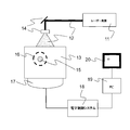
本発明の実施の形態について図面を参照しながら説明する。図1は、本発明の光音響イメージング方法を適用できる光音響イメージング装置の構成の一例を示したものである。光音響イメージング装置は、悪性腫瘍や血管疾患などの診断や化学治療の経過観察などを目的として、生体情報の画像化を可能とするものである。本発明において生体情報とは、光照射によって生じた音響波の発生源分布であり、生体内の初期音圧分布、あるいはそれから導かれる光エネルギー吸収密度分布及び、それらの情報から得られる生体組織を構成する物質の濃度分布を示す。例えば、物質の濃度分布とは酸素飽和度などである。 Embodiments of the present invention will be described with reference to the drawings. FIG. 1 shows an example of the configuration of a photoacoustic imaging apparatus to which the photoacoustic imaging method of the present invention can be applied. The photoacoustic imaging apparatus enables imaging of biological information for the purpose of diagnosing malignant tumors, vascular diseases and the like, and observing the progress of chemotherapy. In the present invention, the biological information is a source distribution of acoustic waves generated by light irradiation, and an initial sound pressure distribution in the living body, or a light energy absorption density distribution derived therefrom, and a living tissue obtained from the information. The concentration distribution of the constituent substances is shown. For example, the substance concentration distribution is oxygen saturation.
生体情報イメージング装置は、光源11、光学装置14、音響波検出器(探触子ともいう)17、電子制御システム18、信号処理装置19、表示装置20から構成される。光源11は、光12を発する装置である。光学装置14は、例えばレンズ、ミラー、光ファイバなどで構成される光学系である。光源11から発せられた光12は光学装置14により導かれ、生体などの被検体13に照射される。被検体13の内部を伝播した光のエネルギーの一部が血管などの光吸収体15に吸収されると、その光吸収体15から音響波(典型的には超音波)16が発生する。これが光音響波である。音響波検出器17は、光吸収体15から発生した音響波16を検出し、電気信号に変換する。電子制御システム18は、音響波検出器17から出力される電気信号の増幅やデジタル変換などを行う制御部である。信号処理装置19は、電子制御システム18から出力されるデジタル信号(検出信号)に基づいて、被検体内部の情報を画像化し出力する装置であり、例えばパーソナル・コンピュータ(PC)で構成される。表示装置20は画像を表示する装置である。
The biological information imaging apparatus includes a
被検体に照射する光12をエネルギーが連続的に変化するパルスなどにすることで、生体内部にある光吸収体15からは熱膨張により音響波16が発生する。これは、パルス光の吸収により、光吸収体15の温度が上昇し、その温度上昇により体積膨張が起こり、音響波が発生するためである。このときの光パルスの時間幅は、光吸収体15に吸収エネルギーを効率に閉じ込めるために、熱・ストレス閉じ込め条件が当てはまる程度にすることが好ましい。典型的には数ナノ秒から数十ナノ秒程度である。
An
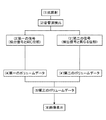
次に、光音響イメージング方法のフローを図2のフローチャートで説明する。(1)まず、光源11から被検体13へパルス光が照射される。(2)光照射により被検体内部で発生した音響波16が音響波検出器17で検出され、電子制御システム18でデジタル信号に変換される。(3)信号処理装置19が(2)で取得された検出信号から第一の信号を生成する。第一の信号は、検出信号そのものでもよいし、検出信号の振幅を調整した信号でもよい。少なくとも検出信号と第一の信号の位相特性が同じ(つまり各周波数成分の位相が一致)であればよい。(4)信号処理装置19は第一の信号を投影データとして用いて、第一のボリュームデータを形成する。投影データからボリュームデータへの変換には従来公知の方法を含むいずれの方法を用いてもよい。(3´)一方、信号処理装置19は第一の信号の位相を変化させることで第二の信号を生成する。例えば、信号処理装置19はフーリエ変換によって第一の信号を周波数分解し、各周波数成分の位相を変化させた後、フーリエ逆変換によって時間領域の信号である第二の信号を得る。つまり第二の信号は第一の信号と振幅特性は同じであるが位相特性は異なる信号である。(4´)信号処理装置19は第二の信号を投影データとして用いて、第二のボリュームデータを形成する。(5)信号処理装置19は第一と第二のボリュームデータから第三のボリュームデータを形成する。例えば、第一と第二のボリュームデータの二乗和の平方根もしくは絶対値の和、またはそれらに比例する値を、第三のボリュームデータのボクセル値とすることができ
る。あるいは、第一と第二のボリュームデータの相加平均や相乗平均を算出してもよい。(6)信号処理装置19は第三のボリュームデータから最終的な出力画像を生成し、表示装置20に出力する。
Next, the flow of the photoacoustic imaging method will be described with reference to the flowchart of FIG. (1) First, pulse light is irradiated from the
図2の(3)において、信号処理装置19が、音響波の回折や減衰を補正するために検出信号の振幅を調整することが好ましい。例えば、光を照射してから音響波を検出(受信)するまでの時間に比例した係数を検出信号に掛けたものを、第一の信号とすることができる。発生する音響波は球面波の重ね合せのため、伝播距離に比例してエネルギー密度が減衰する。上記のように音響波検出器の受信時刻に応じた係数を乗算することで、音響波の減衰を打ち消すことが可能である。
In (3) of FIG. 2, it is preferable that the
また、(3´)において、信号処理装置19が、第一の信号に含まれる正周波数成分の位相を90度遅らせるとともに、負周波数成分の位相を90度早めることにより、第二の信号を生成することが好ましい。なお、ここで示した第二の信号は第一の信号をヒルベルト変換したものと等価である。
Further, in (3 ′), the
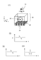
図3は、光照射により得られる信号の一例を示している。図3中の符号(1)(2)(3)(3´)は図2中の符号と対応している。図3の(1)で示されるように、光31を被検体32に照射し、被検体内の光吸収体33から発生した音響波35を音響波検出器34で検出する。ここでは簡単のために、光吸収体33が球体であり、さらに球体全体が光を均一に吸収すると仮定する。また、音響波検出器34は複数の検出エレメントが2次元的に配置されたアレイ型であり、光照射面に対して対向する面に設置されていると仮定する。このような仮定のもとで、ある検出エレメントで検出される検出信号は図3の(2)のようなN形状をしたN型信号になる(横軸は時間、縦軸は音圧である。)。なお、実際の系において観測される光音響信号は、音響波検出器の帯域や大きさを反映した検出器のインパルス応答をN型信号にコンボリューションしたものになるが、ここでは簡単化のため、省略している。また、このN型信号の時間幅は光吸収体33の直径を音速で割ったものであり、N型信号の中心と光照射時刻との間の時間幅は検出エレメントの位置と光吸収体の中心位置の距離を音速で割ったものに等しい。図3の(3)は第一の信号を示している。第一の信号は検出信号と同じ位相特性を有している(つまり第一の信号は検出信号と同一または相似の波形を有している)。図3の(3´)は第一の信号をヒルベルト変換することで得られた第二の信号を示している。第一の信号がN型信号の場合、N型信号の中心部分が正となり、両端部分が負になるような波形の第二の信号が得られる。
FIG. 3 shows an example of a signal obtained by light irradiation. Reference numerals (1), (2), (3), and (3 ') in FIG. 3 correspond to the reference numerals in FIG. As shown in FIG. 3 (1), the
図4は、図3の(1)に示したモデルで測定された信号から得たボリュームデータの例である。なお、ここでは音響波検出器34のエレメント幅の影響を考慮するために、エレメントサイズを2mm×2mmとし、18×18エレメントで音響波の検出を行った。図4の上部の画像は、XY面から見たボリュームデータのMIP(Maximum Intensity Projection)画像、つ
まりボリュームデータのZ方向の最大輝度をXY面に投影した画像である。図4の下部の画像は、XZ面から見たボリュームデータのMIP画像である。図4は、左から順に、第一のボ
リュームデータ、第二のボリュームデータ、第三のボリュームデータ(二乗和の平方根)、第三のボリュームデータ(絶対値の和)、一般的なUBP法によるボリュームデータを示
している。図4の例では、式(3)の投影データに第一の信号を代入することで第一のボリ
ュームデータを計算している。第二のボリュームデータについても同様である。しかしながら、逆投影方法は式(3)に示した方法に限るのではなく、フーリエ変換法やラドン変換
を用いたフィルター補正逆投影法など従来公知のいずれの方法も利用することができる。
FIG. 4 is an example of volume data obtained from a signal measured with the model shown in (1) of FIG. Here, in order to consider the influence of the element width of the
第三のボリュームデータ(二乗和の平方根)は、第一のボリュームデータのボクセル値の二乗と第二のボリュームデータのボクセル値(ボクセルデータ)の二乗を加算し、その平方根を取ったものである。また、第三のボリュームデータ(絶対値の和)は、第一のボ
リュームデータのボクセル値の絶対値と第二のボリュームデータのボクセル値の絶対値を加算したものである。
The third volume data (the square root of the sum of squares) is obtained by adding the square of the voxel value of the first volume data and the square of the voxel value (voxel data) of the second volume data and taking the square root. . The third volume data (sum of absolute values) is obtained by adding the absolute value of the voxel value of the first volume data and the absolute value of the voxel value of the second volume data.
従来のUBP法のボリュームデータと比べ、第三のボリュームデータの方が、より球形に
近い画像が得られていることがわかる。また、図4からは判別しにくいが、球体から放射状に発生するアーティファクトの影響が、UBP法のボリュームデータよりも第三のボリュ
ームデータの方が小さくなっている。これらの画質向上は以下の理由によるものと考えられる。第一に、ボリュームデータの計算に検出信号の微分値を用いないため、高周波ノイズの影響を受けにくい。第二に、異なる信号から形成された第一と第二のボリュームデータは異なるアーティファクトを示すので、それらを合成することで相対的にアーティファクトを低減することが可能である。
It can be seen that the image of the third volume data is more spherical than the conventional UBP volume data. Further, although it is difficult to discriminate from FIG. 4, the third volume data is smaller than the volume data of the UBP method because of the influence of artifacts generated radially from the sphere. These image quality improvements are thought to be due to the following reasons. First, since the differential value of the detection signal is not used in the volume data calculation, it is less susceptible to high frequency noise. Second, since the first and second volume data formed from different signals show different artifacts, it is possible to relatively reduce the artifacts by combining them.
次に、本実施形態を具体的に説明する。
図1において、光源11は生体を構成する成分のうち特定の成分に吸収される特定の波長の光を照射することを目的とする。ただし、光源は本発明の光音響イメージング装置と一体として設けられていても良いし、光源を分離して別体として設けられていても良い。光源としては数ナノから数百ナノ秒オーダーのパルス光を発生可能なパルス光源を少なくとも一つは備える。なお、検出する音響波の音圧が小さくてよい場合は、上記で記述したオーダーのパルス光ではなく、サイン波など時間的に強度(エネルギー)が変化する光であればよい。光源としては大きな出力が得られるレーザーが好ましいが、レーザーのかわりに発光ダイオードなどを用いることも可能である。レーザーとしては、固体レーザー、ガスレーザー、色素レーザー、半導体レーザーなど様々なレーザーを使用することができる。照射のタイミング、波形、強度などは信号処理装置19または不図示の制御部によって制御される。
Next, this embodiment will be specifically described.
In FIG. 1, a
なお、本実施形態においては、光源11が一つである例を示しているが、複数の光源を用いても良い。その場合は、生体に照射する光の照射強度を上げるため、同じ波長を発振する光源を複数用いても良いし、光学特性値分布の波長による違いを測定するために、発振波長の異なる光源を複数個用いても良い。光源11として、発振する波長の変換可能な色素やOPO(Optical Parametric Oscillators)やチタンサファイヤ及びアレキサンドライ
トの結晶を用いることができれば、光学特性値分布の波長による違いを測定することも可能になる。使用する光源の波長に関しては、生体内において吸収が少ない700nmから1100nmの領域が好ましい。ただし、比較的生体表面付近の生体組織の光学特性値分布を求める
場合は、上記の波長領域よりも範囲の広い、例えば400nmから1600nmの波長領域を使用す
ることも可能である。
In the present embodiment, an example in which there is one
光源11から照射された光12を光導波路などを用いて伝搬させることも可能である。光導波路としては、光ファイバが好ましい。光ファイバを用いる場合は、それぞれの光源に対して複数の光ファイバを使用して、生体表面に光を導くことも可能であるし、複数の光源からの光を一本の光ファイバに導き、一本の光ファイバのみを用いて、すべての光を生体に導いても良い。光学装置14は、例えば光を反射するミラーや、光を集光したり拡大したり形状を変化させるレンズなどである。このような光学部品は、光源から発せられた光12が被検体13に所望の形状で照射されれば、どのようなものを用いてもかまわない。なお、一般的に光はレンズで集光させるより、ある程度の面積に広げる方が好ましい。また、光を被検体に照射する領域は移動可能であることが好ましい。言い換えると、本発明の光音響イメージング装置は、光源から発生した光が被検体上を移動可能となるように構成されていることが好ましい。移動可能であることにより、より広範囲に光を照射することができる。また、光を被検体に照射する領域(被検体に照射される光)は、音響波検出器17と同期して移動するとさらに好ましい。光を被検体に照射する領域を移動させる方法としては、可動式ミラー等を用いる方法、光源自体を機械的に移動させる方法など
がある。
It is also possible to propagate the light 12 emitted from the
本発明の光音響イメージング装置は、人や動物の悪性腫瘍や血管疾患などの診断や化学治療の経過観察などを目的としている。よって被検体13としては、人体や動物の乳房や指・手足などの診断の対象部位が想定される。光吸収体15としては、被検体内で吸収係数が高いものを示し、例えば、人体が測定対象であれば酸化あるいは還元ヘモグロビンやそれらを含む多く含む血管あるいは新生血管を多く含む悪性腫瘍が該当する。また、被検体の外部から導入した造影剤を光吸収体として利用することもできる。
The photoacoustic imaging apparatus of the present invention is intended for the diagnosis of human or animal malignant tumors, vascular diseases, etc., the follow-up of chemical therapy, and the like. Accordingly, the subject 13 is assumed to be a target region for diagnosis such as a breast of a human body or an animal, a finger, a limb or the like. Examples of the
音響波検出器17は、圧電現象を用いたトランスデューサー、光の共振を用いたトランスデューサー、容量の変化を用いたトランスデューサーなどで構成される。音響波を検知できるものであれば、どのような音響波検出器17を用いてもよい。本発明の光音響イメージング装置における音響波検出器17は、複数の検出エレメントが2次元的に配置されたものがよい。このような2次元配列素子を用いることで、同時に複数の場所で音響波を検出することができ、検出時間を短縮できると共に、被検体の振動などの影響を低減できる。また、音響波検出器17と被検体との間には、図示してはしないが音響波の反射を抑えるためのジェルや水などの音響インピーダンスマッチング剤を使うことが望ましい。
The
電子制御システム18は音響波検出器17より得られた電気信号を増幅し、それをアナログ信号からデジタル信号に変換する。信号処理装置19は、電子制御システム18から得られた測定データ(検出信号)から上述した第一の信号及び第二の信号を生成し、それらの信号を光学特性値分布の画像データ(ボリュームデータ)に変換する。信号処理装置19は、例えば、CPU(中央演算処理装置)、主記憶装置(メモリ)、補助記憶装置(ハードディスクなど)、入力装置などを備えるコンピュータで構成することができる。コンピュータの補助記憶装置には、信号処理装置19の機能を実現するためのプログラムが格納されている。CPUが補助記憶装置からプログラムを主記憶装置にロードし実行することにより、図2の(3)〜(6)の処理ステップが実行され、測定データのデータ解析が行われる。なお、データ解析手法(画像再構成手法)としては通常の光音響トモグラフィーで使われているフィルタ補正逆投影法、フーリエ変換法、球状ラドン変換法、合成開口法などを用いることができる。表示装置20は信号処理装置19で作られた画像データを表示できれば、どのようなものでも用いることができ、例えば、液晶ディスプレイなどを利用できる。
The
なお、複数の波長の光を用いた場合は、それぞれの波長に関して、上記のシステムにより被検体内の吸収係数分布を算出する。そして、それらの値と生体組織を構成する物質(グルコース、コラーゲン、酸化・還元ヘモグロビンなど)固有の波長依存性とを比較することによって、生体を構成する物質の濃度分布を画像化することも可能である。 When light having a plurality of wavelengths is used, the absorption coefficient distribution in the subject is calculated by the above system for each wavelength. It is also possible to image the concentration distribution of the substances that make up the living body by comparing these values with the wavelength dependence of the substances that make up the living tissue (glucose, collagen, oxidized / reduced hemoglobin, etc.) It is.
11…レーザー光源、12…光、13…被検体、16…音響波、17…音響波検出器、19…信号処理装置
DESCRIPTION OF
Claims (7)
前記光により前記被検体内で発生した光音響波を検出する検出器と、
前記検出器から取得される検出信号に基づいて、前記被検体内部の情報を画像化し出力する信号処理装置と、を備え、
前記信号処理装置は、
前記検出信号または前記検出信号の振幅を調整した信号である第一の信号から第一のボリュームデータを形成し、
前記第一の信号の位相を変化させた信号である第二の信号から第二のボリュームデータを形成し、
前記第一のボリュームデータと前記第二のボリュームデータとから第三のボリュームデータを形成し、
前記第三のボリュームデータから出力画像を生成する
ことを特徴とする光音響イメージング装置。 A light source for irradiating the subject with light;
A detector for detecting a photoacoustic wave generated in the subject by the light;
A signal processing device that images and outputs information inside the subject based on a detection signal acquired from the detector;
The signal processing device includes:
Forming the first volume data from the first signal which is the detection signal or a signal obtained by adjusting the amplitude of the detection signal;
Forming the second volume data from the second signal which is a signal obtained by changing the phase of the first signal;
Forming third volume data from the first volume data and the second volume data;
A photoacoustic imaging apparatus, wherein an output image is generated from the third volume data.
被検体に照射した光により前記被検体内で発生した光音響波を検出器で検出するステップと、
前記検出器から取得された検出信号または前記検出信号の振幅を調整した信号である第一の信号から第一のボリュームデータを形成するステップと、
前記第一の信号の位相を変化させた信号である第二の信号から第二のボリュームデータを形成するステップと、
前記第一のボリュームデータと前記第二のボリュームデータとから第三のボリュームデータを形成するステップと、
前記第三のボリュームデータから前記被検体内部の情報を表す画像を生成し出力するステップと、
を備えることを特徴とする光音響イメージング方法。 A photoacoustic imaging method used in a photoacoustic imaging apparatus,
Detecting a photoacoustic wave generated in the subject by light irradiated on the subject with a detector;
Forming first volume data from a first signal that is a detection signal acquired from the detector or a signal obtained by adjusting the amplitude of the detection signal;
Forming second volume data from a second signal which is a signal obtained by changing the phase of the first signal;
Forming third volume data from the first volume data and the second volume data;
Generating and outputting an image representing information inside the subject from the third volume data;
A photoacoustic imaging method comprising:
被検体に照射した光により前記被検体内で発生した光音響波の検出信号を取得するステップと、
前記取得した検出信号または前記検出信号の振幅を調整した信号である第一の信号から第一のボリュームデータを形成するステップと、
前記第一の信号の位相を変化させた信号である第二の信号から第二のボリュームデータを形成するステップと、
前記第一のボリュームデータと前記第二のボリュームデータとから第三のボリュームデータを形成するステップと、
前記第三のボリュームデータから前記被検体内部の情報を表す画像を生成し出力するステップと、
を実行させることを特徴とするプログラム。 On the computer,
Obtaining a detection signal of a photoacoustic wave generated in the subject by light irradiated on the subject;
Forming first volume data from a first signal that is the acquired detection signal or a signal in which the amplitude of the detection signal is adjusted;
Forming second volume data from a second signal which is a signal obtained by changing the phase of the first signal;
Forming third volume data from the first volume data and the second volume data;
Generating and outputting an image representing information inside the subject from the third volume data;
A program characterized by having executed.
Priority Applications (2)
| Application Number | Priority Date | Filing Date | Title |
|---|---|---|---|
| JP2009152543A JP2011005042A (en) | 2009-06-26 | 2009-06-26 | Photoacoustic imaging apparatus and photoacoustic imaging method |
| US12/816,556 US8260403B2 (en) | 2009-06-26 | 2010-06-16 | Photoacoustic imaging apparatus and photoacoustic imaging method |
Applications Claiming Priority (1)
| Application Number | Priority Date | Filing Date | Title |
|---|---|---|---|
| JP2009152543A JP2011005042A (en) | 2009-06-26 | 2009-06-26 | Photoacoustic imaging apparatus and photoacoustic imaging method |
Publications (2)
| Publication Number | Publication Date |
|---|---|
| JP2011005042A true JP2011005042A (en) | 2011-01-13 |
| JP2011005042A5 JP2011005042A5 (en) | 2012-07-05 |
Family
ID=43381488
Family Applications (1)
| Application Number | Title | Priority Date | Filing Date |
|---|---|---|---|
| JP2009152543A Pending JP2011005042A (en) | 2009-06-26 | 2009-06-26 | Photoacoustic imaging apparatus and photoacoustic imaging method |
Country Status (2)
| Country | Link |
|---|---|
| US (1) | US8260403B2 (en) |
| JP (1) | JP2011005042A (en) |
Cited By (6)
| Publication number | Priority date | Publication date | Assignee | Title |
|---|---|---|---|---|
| WO2012132302A1 (en) | 2011-03-29 | 2012-10-04 | 富士フイルム株式会社 | Photoacoustic imaging method and device |
| JP2013055988A (en) * | 2011-09-07 | 2013-03-28 | Canon Inc | Apparatus and method for acquiring subject information |
| JP2013176414A (en) * | 2012-02-28 | 2013-09-09 | Fujifilm Corp | Photoacoustic image generating apparatus and method |
| JP2015223210A (en) * | 2014-05-26 | 2015-12-14 | キヤノン株式会社 | Subject information acquisition device |
| US10265047B2 (en) | 2014-03-12 | 2019-04-23 | Fujifilm Sonosite, Inc. | High frequency ultrasound transducer having an ultrasonic lens with integral central matching layer |
| US10478859B2 (en) | 2006-03-02 | 2019-11-19 | Fujifilm Sonosite, Inc. | High frequency ultrasonic transducer and matching layer comprising cyanoacrylate |
Families Citing this family (20)
| Publication number | Priority date | Publication date | Assignee | Title |
|---|---|---|---|---|
| US8938104B2 (en) * | 2008-08-29 | 2015-01-20 | Varian Medical Systems International Ag | Systems and methods for adaptive filtering |
| JP5419404B2 (en) * | 2008-09-04 | 2014-02-19 | キヤノン株式会社 | Photoacoustic device |
| JP5528083B2 (en) | 2009-12-11 | 2014-06-25 | キヤノン株式会社 | Image generating apparatus, image generating method, and program |
| JP5675390B2 (en) * | 2010-02-09 | 2015-02-25 | キヤノン株式会社 | measuring device |
| JP5441781B2 (en) * | 2010-03-25 | 2014-03-12 | キヤノン株式会社 | Photoacoustic imaging apparatus, photoacoustic imaging method, and program |
| JP5777358B2 (en) | 2010-04-27 | 2015-09-09 | キヤノン株式会社 | Subject information acquisition apparatus and signal processing method |
| TWI403784B (en) * | 2010-12-31 | 2013-08-01 | Pai Chi Li | Photoacoustic imaging system, coded laser emitting apparatus and photoacoustic signal receiving apparatus |
| JP5850633B2 (en) | 2011-04-12 | 2016-02-03 | キヤノン株式会社 | Subject information acquisition device |
| JP5932243B2 (en) * | 2011-05-31 | 2016-06-08 | キヤノン株式会社 | apparatus |
| KR101273585B1 (en) | 2011-12-05 | 2013-06-11 | 삼성전자주식회사 | Ultrasound imaging apparatus and display method of ultrasound image |
| JP5871958B2 (en) * | 2012-01-18 | 2016-03-01 | キヤノン株式会社 | Subject information acquisition apparatus and subject information acquisition method |
| WO2013134782A1 (en) | 2012-03-09 | 2013-09-12 | The Johns Hopkins University | Photoacoustic tracking and registration in interventional ultrasound |
| US20140182383A1 (en) * | 2012-12-28 | 2014-07-03 | Canon Kabushiki Kaisha | Object information obtaining device, display method, and non-transitory computer-readable storage medium |
| JP6222936B2 (en) | 2013-02-19 | 2017-11-01 | キヤノン株式会社 | Apparatus and image generation method |
| US10456044B2 (en) | 2013-11-22 | 2019-10-29 | Massachusetts Institute Of Technology | Systems and methods for generating non-contact ultrasound images using photoacoustic energy |
| CN104318619B (en) * | 2014-10-20 | 2017-07-18 | 西北工业大学 | The method for reconstructing perceived towards the self-adapting compressing of Non-Destructive Testing |
| US10806346B2 (en) * | 2015-02-09 | 2020-10-20 | The Johns Hopkins University | Photoacoustic tracking and registration in interventional ultrasound |
| JP2017086172A (en) * | 2015-11-02 | 2017-05-25 | キヤノン株式会社 | Subject information acquisition device and control method thereof |
| WO2017160858A1 (en) | 2016-03-14 | 2017-09-21 | Massachusetts Institute Of Technology | System and method for non-contact ultrasound with enhanced safety |
| CN108535194B (en) * | 2018-03-22 | 2021-01-08 | 深圳大学 | Photoacoustic microscopic imaging system and method based on surface plasma resonance |
Citations (2)
| Publication number | Priority date | Publication date | Assignee | Title |
|---|---|---|---|---|
| JP2007533274A (en) * | 2004-04-19 | 2007-11-15 | ランドマーク、ディジタル、サーヴィセズ、エルエルシー | Method and system for content sampling and identification |
| WO2008075961A2 (en) * | 2006-12-21 | 2008-06-26 | Universiteit Twente | Imaging apparatus and method |
Family Cites Families (15)
| Publication number | Priority date | Publication date | Assignee | Title |
|---|---|---|---|---|
| US20080306471A1 (en) * | 2000-12-28 | 2008-12-11 | Palomar Medical Technologies, Inc. | Methods and devices for fractional ablation of tissue |
| US6426990B1 (en) * | 2001-06-28 | 2002-07-30 | General Electric Company | Methods and apparatus for coronary-specific imaging reconstruction |
| US6718004B2 (en) * | 2001-06-28 | 2004-04-06 | General Electric Company | Methods and apparatus for coronary-specific imaging reconstruction |
| US6638230B2 (en) * | 2001-07-31 | 2003-10-28 | Koninklijke Philips Electronics N.V. | Apparatus and method of frequency compounding to perform contrast imaging |
| WO2003101301A1 (en) * | 2002-06-03 | 2003-12-11 | Hitachi Medical Corporation | Multi-slice x-ray ct device |
| WO2005077278A1 (en) * | 2004-02-16 | 2005-08-25 | Hitachi Medical Corporation | Tomogram reconstruction method and tomograph |
| US7525661B2 (en) * | 2004-02-17 | 2009-04-28 | Andreas Mandelis | Laser photo-thermo-acoustic (PTA) frequency swept heterodyned lock-in depth profilometry imaging system |
| US7862508B2 (en) * | 2004-09-20 | 2011-01-04 | Innervision Medical Technologies Inc. | Systems and methods for ultrasound imaging |
| US8234923B2 (en) * | 2004-09-20 | 2012-08-07 | Innervision Medical Technologies Inc. | Systems and methods for ultrasound imaging |
| US20080294150A1 (en) * | 2005-04-01 | 2008-11-27 | Palomar Medical Technologies, Inc. | Photoselective Islets In Skin And Other Tissues |
| US20070083109A1 (en) * | 2005-09-28 | 2007-04-12 | Ustuner Kutay F | Adaptive line synthesis for ultrasound |
| US8064986B2 (en) * | 2005-11-23 | 2011-11-22 | General Electric Company | Method and system for displaying a cine loop formed from combined 4D volumes |
| DE102006011242B4 (en) * | 2006-03-10 | 2012-03-29 | Siemens Ag | Method for reconstructing a 3D representation |
| TWI326354B (en) * | 2007-05-18 | 2010-06-21 | Univ Nat Taipei Technology | Method and apparatus for simultaneously acquiring interferograms and method for solving the phase |
| JP5052223B2 (en) * | 2007-06-26 | 2012-10-17 | 三菱電機株式会社 | Image display device, image processing circuit, and image display method |
-
2009
- 2009-06-26 JP JP2009152543A patent/JP2011005042A/en active Pending
-
2010
- 2010-06-16 US US12/816,556 patent/US8260403B2/en not_active Expired - Fee Related
Patent Citations (2)
| Publication number | Priority date | Publication date | Assignee | Title |
|---|---|---|---|---|
| JP2007533274A (en) * | 2004-04-19 | 2007-11-15 | ランドマーク、ディジタル、サーヴィセズ、エルエルシー | Method and system for content sampling and identification |
| WO2008075961A2 (en) * | 2006-12-21 | 2008-06-26 | Universiteit Twente | Imaging apparatus and method |
Non-Patent Citations (2)
| Title |
|---|
| CSNB201000946001; 三上 直樹 NAOKI MIKAMI: 改訂新版 C/C++によるディジタル信号処理入門 初版 第1版, 20090215, 第199-206頁, CQ出版株式会社 山岸 誠仁 * |
| JPN6013054272; 三上 直樹 NAOKI MIKAMI: 改訂新版 C/C++によるディジタル信号処理入門 初版 第1版, 20090215, 第199-206頁, CQ出版株式会社 山岸 誠仁 * |
Cited By (12)
| Publication number | Priority date | Publication date | Assignee | Title |
|---|---|---|---|---|
| US10478859B2 (en) | 2006-03-02 | 2019-11-19 | Fujifilm Sonosite, Inc. | High frequency ultrasonic transducer and matching layer comprising cyanoacrylate |
| WO2012132302A1 (en) | 2011-03-29 | 2012-10-04 | 富士フイルム株式会社 | Photoacoustic imaging method and device |
| JP2012213609A (en) * | 2011-03-29 | 2012-11-08 | Fujifilm Corp | Photoacoustic imaging method and apparatus |
| CN103458797A (en) * | 2011-03-29 | 2013-12-18 | 富士胶片株式会社 | Photoacoustic imaging method and device |
| US9320475B2 (en) | 2011-03-29 | 2016-04-26 | Fujifilm Corporation | Photoacoustic imaging method and photoacoustic imaging apparatus |
| US10052028B2 (en) | 2011-03-29 | 2018-08-21 | Fujifilm Corporation | Photoacoustic imaging method and photoacoustic imaging apparatus |
| JP2013055988A (en) * | 2011-09-07 | 2013-03-28 | Canon Inc | Apparatus and method for acquiring subject information |
| JP2013176414A (en) * | 2012-02-28 | 2013-09-09 | Fujifilm Corp | Photoacoustic image generating apparatus and method |
| US10265047B2 (en) | 2014-03-12 | 2019-04-23 | Fujifilm Sonosite, Inc. | High frequency ultrasound transducer having an ultrasonic lens with integral central matching layer |
| US11083433B2 (en) | 2014-03-12 | 2021-08-10 | Fujifilm Sonosite, Inc. | Method of manufacturing high frequency ultrasound transducer having an ultrasonic lens with integral central matching layer |
| US11931203B2 (en) | 2014-03-12 | 2024-03-19 | Fujifilm Sonosite, Inc. | Manufacturing method of a high frequency ultrasound transducer having an ultrasonic lens with integral central matching layer |
| JP2015223210A (en) * | 2014-05-26 | 2015-12-14 | キヤノン株式会社 | Subject information acquisition device |
Also Published As
| Publication number | Publication date |
|---|---|
| US20100331662A1 (en) | 2010-12-30 |
| US8260403B2 (en) | 2012-09-04 |
Similar Documents
| Publication | Publication Date | Title |
|---|---|---|
| JP2011005042A (en) | Photoacoustic imaging apparatus and photoacoustic imaging method | |
| JP5837115B2 (en) | Subject information acquisition device | |
| JP4469903B2 (en) | Biological information imaging device | |
| JP5675390B2 (en) | measuring device | |
| JP2010088627A5 (en) | ||
| JP2010088627A (en) | Apparatus and method for processing biological information | |
| JP5197217B2 (en) | Biological information imaging apparatus and image construction method | |
| JP5305818B2 (en) | Biological information acquisition device | |
| JP2011217914A (en) | Photoacoustic imaging apparatus, photoacoustic imaging method, and program | |
| US20140296690A1 (en) | Object information acquiring apparatus and object information acquiring method | |
| JP2017029610A (en) | Photoacoustic apparatus, reliability acquisition method, and program | |
| EP3184032A1 (en) | Photoacoustic apparatus, information acquiring apparatus, information acquiring method, and program | |
| KR101899838B1 (en) | Photoacoustic apparatus and information acquisition apparatus | |
| JP6238736B2 (en) | Photoacoustic apparatus, signal processing method, and program | |
| JP6562800B2 (en) | Processing apparatus and processing method | |
| JP2013188489A (en) | Subject information processing apparatus and method for operating the same | |
| JP6469133B2 (en) | Processing apparatus, photoacoustic apparatus, processing method, and program | |
| JP6512969B2 (en) | PROCESSING APPARATUS, PHOTOACOUSTIC APPARATUS, PROCESSING METHOD, AND PROGRAM | |
| JP6701005B2 (en) | Device and information processing method | |
| JP5680141B2 (en) | SUBJECT INFORMATION ACQUISITION DEVICE AND METHOD FOR CONTROLLING SUBJECT INFORMATION ACQUISITION DEVICE | |
| JP2018000305A (en) | Subject information acquisition device and signal processing method | |
| JP5669889B2 (en) | Biological information acquisition device | |
| JP2015083219A (en) | Subject information acquisition device and control method for subject information acquisition device | |
| JP2017086173A (en) | Subject information acquisition device and control method thereof |
Legal Events
| Date | Code | Title | Description |
|---|---|---|---|
| A521 | Request for written amendment filed |
Free format text: JAPANESE INTERMEDIATE CODE: A523 Effective date: 20120521 |
|
| A621 | Written request for application examination |
Free format text: JAPANESE INTERMEDIATE CODE: A621 Effective date: 20120521 |
|
| A131 | Notification of reasons for refusal |
Free format text: JAPANESE INTERMEDIATE CODE: A131 Effective date: 20130625 |
|
| A977 | Report on retrieval |
Free format text: JAPANESE INTERMEDIATE CODE: A971007 Effective date: 20130628 |
|
| A521 | Request for written amendment filed |
Free format text: JAPANESE INTERMEDIATE CODE: A523 Effective date: 20130819 |
|
| A02 | Decision of refusal |
Free format text: JAPANESE INTERMEDIATE CODE: A02 Effective date: 20131105 |