JP6597656B2 - Vehicle display device - Google Patents

Vehicle display device Download PDF

Info

Publication number
JP6597656B2
JP6597656B2 JP2017010424A JP2017010424A JP6597656B2 JP 6597656 B2 JP6597656 B2 JP 6597656B2 JP 2017010424 A JP2017010424 A JP 2017010424A JP 2017010424 A JP2017010424 A JP 2017010424A JP 6597656 B2 JP6597656 B2 JP 6597656B2
Authority
JP
Japan
Prior art keywords
display
warning
translucent
light
unit
Prior art date
Legal status (The legal status is an assumption and is not a legal conclusion. Google has not performed a legal analysis and makes no representation as to the accuracy of the status listed.)
Expired - Fee Related
Application number
JP2017010424A
Other languages
Japanese (ja)
Other versions
JP2018118581A (en
Inventor
浩三 小野
克己 藤田
拓夫 山本
全志 中村
Current Assignee (The listed assignees may be inaccurate. Google has not performed a legal analysis and makes no representation or warranty as to the accuracy of the list.)
Denso Corp
Original Assignee
Denso Corp
Priority date (The priority date is an assumption and is not a legal conclusion. Google has not performed a legal analysis and makes no representation as to the accuracy of the date listed.)
Filing date
Publication date
Application filed by Denso Corp filed Critical Denso Corp
Priority to JP2017010424A priority Critical patent/JP6597656B2/en
Priority to CN201780069971.3A priority patent/CN109964101B/en
Priority to DE112017005615.2T priority patent/DE112017005615T5/en
Priority to KR1020197010715A priority patent/KR102277852B1/en
Priority to PCT/JP2017/033185 priority patent/WO2018088024A1/en
Publication of JP2018118581A publication Critical patent/JP2018118581A/en
Priority to US16/395,314 priority patent/US11117468B2/en
Application granted granted Critical
Publication of JP6597656B2 publication Critical patent/JP6597656B2/en
Expired - Fee Related legal-status Critical Current
Anticipated expiration legal-status Critical

Links

Images

Description

本発明は、車両に搭載される車両用表示装置に関する。   The present invention relates to a vehicle display device mounted on a vehicle.

従来、車両に搭載される車両用表示装置が知られている。特許文献1に開示の装置は、表示パネル及び表示板を有している。表示パネルは、各種警告メッセージないしは警告灯等の警告を表示可能に形成されている。表示板は、表示パネルよりも視認側に配置され、窓部において警告の表示を透過させる。   Conventionally, a vehicular display device mounted on a vehicle is known. The apparatus disclosed in Patent Document 1 includes a display panel and a display plate. The display panel is configured to display various warning messages or warnings such as warning lights. The display board is arranged on the visual recognition side with respect to the display panel, and transmits a warning display in the window portion.

また、表示板は、窓部以外の領域にヘアライン模様を形成している。表示パネルは、ヘアライン模様に連続した模様を、背景として表示している。   In addition, the display board forms a hairline pattern in a region other than the window portion. The display panel displays a pattern continuous with the hairline pattern as a background.

特開2008−122214号公報JP 2008-122214 A

こうした特許文献1の装置では、警告の表示とヘアライン模様のような表示内容との両方を、同じ表示パネルによって表示しているため、両表示が平面的に視認され、立体感に乏しい。さらに、両表示を同時に表示してしまっているため、警告の表示が目立ち難く、視認性が良好ではなかった。このため、視認者が警告を認識し難いという問題があった。   In such an apparatus of Patent Document 1, since both the warning display and the display content such as the hairline pattern are displayed on the same display panel, both displays are visually recognized in a plane and the stereoscopic effect is poor. Furthermore, since both displays are displayed at the same time, the warning display is not conspicuous and the visibility is not good. For this reason, there was a problem that it was difficult for the viewer to recognize the warning.

本発明は、以上説明した問題に鑑みてなされたものであって、その目的は、立体感を向上すると共に、視認性良好に警告を表示することで、視認者が警告を認識し易い車両用表示装置を提供することにある。   The present invention has been made in view of the above-described problems, and an object thereof is to improve the stereoscopic effect and display a warning with good visibility so that a viewer can easily recognize the warning. It is to provide a display device.

本発明は、車両に搭載される車両用表示装置であって、
警告を表示可能に形成された警告表示部(40a,40b)と、
警告表示部よりも視認側に配置され、警告の表示を透過させる透光板(52)を有し、
透光板において、警告の表示と重畳する領域(SPa,SPb)に警告表示部とは別の表示内容を通常時に点灯表示する透光表示部(50a,50b)と、
警告表示部及び透光表示部の表示を制御する表示制御部(78)と、を備え、
表示制御部は、警告表示部の警告を表示する場合に、透光表示部の表示内容を一時的に消灯させ
透光表示部は、
透光板の内部に光を提供する光源部(58)と、
透光板に形成され、光源部からの光を視認側に反射することにより、表示内容を点灯表示する反射部(54)と、を有し、
反射部は、透光板の外縁部に沿って配列された複数の目盛(67a)を含む目盛図柄(67)を、表示内容として有し、
光源部は、各目盛に個別に対応する複数の発光素子(58a)を有し、
表示制御部は、各発光素子の点灯及び消灯を個別に制御することにより、目盛図柄の目盛の一部又は全部を点灯表示させて、車両の状態を表示させる。
The present invention is a vehicle display device mounted on a vehicle,
Warning display portions (40a, 40b) formed so as to be able to display warnings;
It has a translucent plate (52) that is arranged on the visual recognition side of the warning display part and transmits the display of the warning,
A translucent display unit (50a, 50b) that displays a display content different from the warning display unit in a normal state in a region (SPa, SPb) overlapping the display of the warning in the translucent plate;
A display control unit (78) for controlling the display of the warning display unit and the translucent display unit,
When displaying a warning on the warning display unit, the display control unit temporarily turns off the display content of the translucent display unit ,
The translucent display part
A light source unit (58) for providing light to the inside of the light-transmitting plate;
A reflection part (54) that is formed on the light-transmitting plate and reflects the light from the light source part to the viewer side, thereby lighting the display content.
The reflection part has a scale symbol (67) including a plurality of scales (67a) arranged along the outer edge part of the translucent plate as display contents.
The light source unit has a plurality of light emitting elements (58a) individually corresponding to each scale,
The display control unit controls lighting and extinguishing of each light emitting element individually, thereby lighting or displaying part or all of the scale symbols, and displaying the state of the vehicle.

このような発明によると、透光表示部は、透光板において、警告の表示と重畳する領域に警告表示部とは別の表示内容を点灯表示する。ここで、警告の表示を透過させる透光板は、警告表示部よりも視認側に配置されているので、警告の表示は、透光表示部の表示内容よりも奥に表示されることとなり、立体感を演出できる。そして、通常時に点灯表示されている透光表示部の表示内容は、警告表示部にて警告を表示する場合に、一時的に消灯される。透光表示部の表示内容が消えることで、警告の表示が視認し易くなるだけでなく、消灯による表示の変化によって警告の表示が目立つため、視認者の注目を集め易くなる。以上により、立体感を向上すると共に、視認性良好に警告を表示することで、視認者が警告を認識し易い車両用表示装置を提供することができる。   According to such an invention, the translucent display unit illuminates and displays the display content different from the warning display unit in a region overlapping the display of the warning on the translucent plate. Here, since the translucent plate that transmits the display of the warning is arranged on the viewing side from the warning display unit, the display of the warning is displayed behind the display content of the translucent display unit, A three-dimensional effect can be produced. Then, the display content of the translucent display portion that is normally lit is temporarily turned off when a warning is displayed on the warning display portion. Since the display content of the translucent display portion disappears, not only the warning display becomes easy to visually recognize, but also the warning display becomes conspicuous due to the change in display caused by turning off the light. As described above, it is possible to provide a vehicle display device in which a viewer can easily recognize the warning by improving the stereoscopic effect and displaying the warning with good visibility.

なお、括弧内の符号は、記載内容の理解を容易にすべく、後述する実施形態において対応する構成を例示するものに留まり、発明の内容を限定することを意図するものではない。   In addition, the code | symbol in a parenthesis is only what exemplifies the structure which respond | corresponds in embodiment mentioned later, in order to make an understanding of description content easy, and does not intend limiting the content of invention.

一実施形態における車両用表示装置の正面図である。It is a front view of the display apparatus for vehicles in one embodiment. 図1のII−II線断面図である。It is the II-II sectional view taken on the line of FIG. 一実施形態における遮光区画部を透光板側からみた図である。It is the figure which looked at the light-shielding division part in one Embodiment from the translucent board side. 図3のIV−IV線矢視図である。It is the IV-IV line arrow directional view of FIG. 図4のV−V線矢視図である。FIG. 5 is a view taken along line VV in FIG. 図3のVI−VI線断面において、遮光区画部と透光板及び光源部との位置関係を示す断面図である。FIG. 4 is a cross-sectional view showing a positional relationship between a light shielding section, a translucent plate, and a light source section in the section taken along line VI-VI in FIG. 3. 図3のVII−VII線断面図である。It is the VII-VII sectional view taken on the line of FIG. 図2のVIII部を部分的に拡大した拡大断面図である。It is the expanded sectional view which expanded the VIII part of FIG. 2 partially. 一実施形態における反射部における配列領域を部分的に拡大して示す拡大図である。It is an enlarged view which expands and shows the arrangement field in the reflective part in one embodiment partially. 一実施形態における車両用表示装置の回路等を説明するためのブロック図である。It is a block diagram for demonstrating the circuit etc. of the display apparatus for vehicles in one Embodiment. 一実施形態における車両用表示装置によるフローチャートである。It is a flowchart by the display apparatus for vehicles in one Embodiment. 一実施形態における表示の例を示す図であって、透光表示部が表示状態であり、警報表示部が非表示状態である場合を示す図である。It is a figure which shows the example of the display in one Embodiment, Comprising: It is a figure which shows the case where a translucent display part is a display state and a warning display part is a non-display state. 一実施形態における表示の例を示す図であって、透光表示部が非表示状態であり、警報表示部が表示状態である場合を示す図である。It is a figure which shows the example of the display in one Embodiment, Comprising: It is a figure which shows the case where a translucent display part is a non-display state and an alarm display part is a display state. 一実施形態における表示の例を示す図であって、透光表示部及び警報表示部が重畳表示されている状態である場合を示す図である。It is a figure which shows the example of the display in one Embodiment, Comprising: It is a figure which shows the case where it is the state where the translucent display part and the alarm display part are superimposed and displayed.

以下、本発明の一実施形態を図面に基づいて説明する。   Hereinafter, an embodiment of the present invention will be described with reference to the drawings.

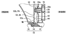
図1に示すように、本発明の一実施形態による車両用表示装置100は、車両に搭載され、当該装置100を視認する乗員が着座する座席と対向するインストルメントパネルに設置されている。車両用表示装置100は、乗員が位置することとなる視認側へ向けて車両の状態を表示可能となっている。   As shown in FIG. 1, a vehicle display device 100 according to an embodiment of the present invention is installed on an instrument panel that is mounted on a vehicle and faces a seat on which an occupant who views the device 100 is seated. The vehicle display device 100 can display the state of the vehicle toward the viewing side where the occupant is located.

このような車両用表示装置100は、図2にも示すように、ケース部10、指針表示部20a,20b、液晶表示部30、警告表示部40a,40b、透光表示部50a,50b、及びメイン回路基板70を備えている。   As shown in FIG. 2, the vehicular display device 100 includes a case unit 10, pointer display units 20a and 20b, a liquid crystal display unit 30, warning display units 40a and 40b, translucent display units 50a and 50b, and A main circuit board 70 is provided.

ケース部10は、背面ケース12、枠ケース14、及びスモーク板16を備えている。背面ケース12は、例えば遮光性を有する合成樹脂により形成され、各表示部20a,20b,30,40a,40b及びメイン回路基板70を背面側から覆っている。枠ケース14は、例えば遮光性を有する合成樹脂により、装置100の外周輪郭に沿って視認側及び当該視認側とは反対側の背面側に開口部を有する筒状に形成されている。スモーク板16は、例えば着色されたアクリル樹脂等の半透光性樹脂により、枠ケース14の視認側開口部の全面を塞ぐ曲面板状に形成されている。これにより、各表示部20a,20b,30,40a,40b,50a,50bは、スモーク板16を通して乗員に視認されることとなる。本実施形態のスモーク板16は、スモーク調の着色により、透過率が30%程度に設定されているが、30%以上の任意の値に設定されていてもよい。   The case unit 10 includes a back case 12, a frame case 14, and a smoke plate 16. The back case 12 is formed of, for example, a synthetic resin having a light shielding property, and covers the display units 20a, 20b, 30, 40a, and 40b and the main circuit board 70 from the back side. The frame case 14 is formed in a cylindrical shape having openings on the viewing side and the back side opposite to the viewing side along the outer peripheral contour of the device 100, for example, with a synthetic resin having a light shielding property. The smoke plate 16 is formed in a curved plate shape that covers the entire viewing side opening of the frame case 14 with a semi-transparent resin such as a colored acrylic resin. Thereby, each display part 20a, 20b, 30, 40a, 40b, 50a, 50b will be visually recognized by the passenger | crew through the smoke board 16. FIG. The smoke plate 16 of the present embodiment is set to have a transmittance of about 30% by smoke-colored coloring, but may be set to an arbitrary value of 30% or more.

指針表示部20a,20bは、指針24が指標22を指示することにより、車両の状態を表示する。指標22は、表示板18に設けられている。表示板18は、一般的に文字板とも呼ばれている。表示板18は、例えば透光性を有する合成樹脂からなる基材の視認側の表面に、半透光性又は遮光性の印刷が部分的に施されて、平板状に形成されている。なお、印刷に代えて、塗装が施されていてもよい。   The pointer display units 20a and 20b display the state of the vehicle when the pointer 24 indicates the index 22. The indicator 22 is provided on the display board 18. The display board 18 is also generally called a dial. The display board 18 is formed in a flat plate shape, for example, by partially applying semi-translucent or light-shielding printing to the surface on the viewing side of a base material made of a synthetic resin having translucency. In addition, it may replace with printing and the coating may be given.

特に本実施形態では、表示板18の左側の領域及び右側の領域にそれぞれ、指針表示部20a,20bが設けられている。ここで、2つの指針表示部20a,20bは互いに同様の構成となっているため、右側の指針表示部20aについて代表して説明する。指針表示部20aの指標22は、表示板18上の印刷により、目盛及び当該目盛に対応する文字を円環状に配列して形成されている。   In particular, in the present embodiment, pointer display portions 20a and 20b are provided in the left area and the right area of the display board 18, respectively. Here, since the two pointer display portions 20a and 20b have the same configuration, the right pointer display portion 20a will be described as a representative. The indicator 22 of the pointer display unit 20a is formed by printing scales and characters corresponding to the scales in an annular shape by printing on the display board 18.

指針24は、連結部24a及び指示部24bを一体的に有している。連結部24aは、表示板18に空けられた貫通穴を通して配置されており、表示板18よりも背面側のメイン回路基板70に保持された指針駆動モータ26(例えばステッピングモータ)の回転軸26aと連結されている。指示部24bは、表示板18よりも視認側に配置され、表示板18に沿って延伸する針状を呈している。指針24は、指針駆動モータ26の出力に応じて回動するようになっている。   The pointer 24 integrally includes a connecting portion 24a and an instruction portion 24b. The connecting portion 24 a is disposed through a through hole formed in the display board 18, and a rotation shaft 26 a of a pointer driving motor 26 (for example, a stepping motor) held on the main circuit board 70 on the rear side of the display board 18. It is connected. The instruction unit 24 b is disposed on the viewing side with respect to the display board 18 and has a needle shape extending along the display board 18. The pointer 24 is rotated in accordance with the output of the pointer drive motor 26.

なお、本実施形態において、右側の領域に対応した指針24は、車両の状態として、車両の速度を表示するようになっている。左側の領域に対応した指針24は、車両の状態として、車両のエンジン回転数を表示するようになっている。   In the present embodiment, the pointer 24 corresponding to the right region displays the vehicle speed as the vehicle state. The pointer 24 corresponding to the left region displays the engine speed of the vehicle as the state of the vehicle.

液晶表示部30は、表示板18の中央の領域に、2つの指針表示部20a,20bに挟まれた配置にて設けられている。液晶表示部30は、表示板18よりも背面側に配置された液晶パネル32からの表示光が表示板18に印刷が設けられないことで形成された透過領域36を視認側に透過することで、画像を表示可能となっている。   The liquid crystal display unit 30 is provided in the central region of the display panel 18 in an arrangement sandwiched between two pointer display units 20a and 20b. The liquid crystal display unit 30 transmits display light from the liquid crystal panel 32 disposed on the back side of the display plate 18 to the viewing side through a transmission region 36 formed by no printing on the display plate 18. The image can be displayed.

本実施形態の液晶パネル32は、薄膜トランジスタ(Thin Film Transistor、TFT)を用いた液晶パネルであって、2次元方向に配列された複数の液晶画素から形成されるアクティブマトリクス型の液晶パネルとなっている。液晶パネル32は、視認側に矩形状の表示面を形成している。液晶パネル32がバックライト34により背面側から照明されて、画像が表示される。   The liquid crystal panel 32 of this embodiment is a liquid crystal panel using thin film transistors (TFTs), and is an active matrix type liquid crystal panel formed from a plurality of liquid crystal pixels arranged in a two-dimensional direction. Yes. The liquid crystal panel 32 forms a rectangular display surface on the viewing side. The liquid crystal panel 32 is illuminated from the back side by the backlight 34, and an image is displayed.

警告表示部40a,40bは、特に本実施形態では各指針表示部20a,20bよりも下側の2箇所に、表示板の外縁部に沿って、それぞれ設けられている。警告表示部40a,40bは、警告を表示可能に形成されている。具体的に、警告表示部40a,40bは、各種警告を示す複数の警告灯42を有している。各警告灯42は、表示板18に印刷されたマークとして形成されている。   In the present embodiment, the warning display portions 40a and 40b are provided at two locations below the pointer display portions 20a and 20b, respectively, along the outer edge portion of the display board. The warning display units 40a and 40b are formed so that warnings can be displayed. Specifically, the warning display units 40a and 40b have a plurality of warning lights 42 indicating various warnings. Each warning lamp 42 is formed as a mark printed on the display board 18.

警告表示部40a,40bは、各警告灯42に個別に対応する複数の発光素子44を、メイン回路基板70に保持された状態で有している。当該警告灯に個別に対応する発光素子44が発光し、当該警告灯42のマークを背面側から照明することにより、警告表示部40a,40bは発光表示される。各発光素子44には、発光ダイオードが採用されており、各発光素子44は電源と接続されることで発光する。   The warning display units 40 a and 40 b have a plurality of light emitting elements 44 individually corresponding to the respective warning lights 42 in a state of being held on the main circuit board 70. The light emitting elements 44 individually corresponding to the warning lamps emit light, and the warning display portions 40a and 40b are lit and displayed by illuminating the mark of the warning lamp 42 from the back side. Each light emitting element 44 employs a light emitting diode, and each light emitting element 44 emits light when connected to a power source.

警告灯42のマークとしては、乗員がシートベルトを着用していないことを示す警告マーク、車両が半ドア状態であることを示す警告マーク、ブレーキに異常が発生していることを示す警告マーク等が存在している。   The warning light 42 includes a warning mark indicating that the occupant is not wearing a seat belt, a warning mark indicating that the vehicle is in a half-door state, a warning mark indicating that an abnormality has occurred in the brake, and the like. Is present.

こうした警告表示部40a,40bの警告表示は、通常時には非表示状態となっており、異常発生時等に表示される。警告表示部40a,40bの警告の表示色は、赤色に設定されているが、他のアンバー(橙色)等の表示色に設定されてもよい。   Such warning display of the warning display portions 40a and 40b is normally not displayed, and is displayed when an abnormality occurs. The warning display color of the warning display units 40a and 40b is set to red, but may be set to another display color such as amber (orange).

透光表示部50a,50bは、警告表示部40a,40bが表示される表示板18よりも視認側に配置されている透光板52を用いて表示を行なう。透光板52は、例えば透光性を有する合成樹脂により、表示板18と略平行に配置された平板状を呈している。そして、透光板52は、その透光性によって、警告表示部40a,40bによる警告の表示を乗員により視認可能に透過させるようになっている。   The translucent display parts 50a and 50b display using the translucent board 52 arrange | positioned rather than the display board 18 on which the warning display parts 40a and 40b are displayed. The translucent plate 52 has a flat plate shape that is disposed substantially in parallel with the display plate 18 by using a synthetic resin having translucency, for example. And the translucent board 52 is made to permeate | transmit the display of the warning by warning display part 40a, 40b so that a passenger | crew can visually recognize with the translucency.

特に本実施形態では、透光板52のうち、各警告表示部40a,40bと対向する2つの領域、すなわち各警告表示部40a,40bによる警告の表示と重畳する2箇所の領域SPa,SPbに対応して、透光表示部50a,50bがそれぞれ設けられている。右側の透光表示部50a及び左側の透光表示部50bは、1つの透光板52を共有し、さらに互いに同様の構成となっているため、以下では右側の透光表示部50aについて代表して説明する。具体的に、透光表示部50aは、光源部58、遮光区画部60及び反射部54を有している。   In particular, in the present embodiment, in the translucent plate 52, two regions SPa and SPb that overlap with the warning display by the respective warning display units 40a and 40b, that is, the two regions SPa and SPb that are opposed to the respective warning display units 40a and 40b. Correspondingly, translucent display portions 50a and 50b are respectively provided. Since the right translucent display unit 50a and the left translucent display unit 50b share one translucent plate 52 and have the same configuration, the right translucent display unit 50a is represented below. I will explain. Specifically, the translucent display unit 50 a includes a light source unit 58, a light shielding partition unit 60, and a reflection unit 54.

光源部58は、光源用回路基板58b上に複数の発光素子58aを配列して形成されている。各発光素子58aには、発光ダイオードが採用されており、各発光素子58aは電源と接続されることで発光する。特に本実施形態では、各発光素子58aがマルチカラーの発光ダイオードとなっているが、点灯状態の発光素子58aは、互いに実質同一の色及び実質同じ輝度で発光を制御されるようになっている。   The light source unit 58 is formed by arranging a plurality of light emitting elements 58a on a light source circuit board 58b. Each light emitting element 58a employs a light emitting diode, and each light emitting element 58a emits light when connected to a power source. In particular, in the present embodiment, each light emitting element 58a is a multi-color light emitting diode, but the light emitting elements 58a in the lit state are controlled to emit light with substantially the same color and substantially the same brightness. .

こうした光源部58は、透光板52の外縁部52aと対向して配置されている。各発光素子58aから発せられた光が当該外縁部52aを介して透光板52の内部に入射することで、光源部58は、透光板52の内部に光を提供可能となっている。   Such a light source part 58 is disposed to face the outer edge part 52 a of the translucent plate 52. The light emitted from each light emitting element 58 a is incident on the inside of the light transmitting plate 52 through the outer edge portion 52 a, so that the light source unit 58 can provide light to the inside of the light transmitting plate 52.

遮光区画部60は、図1,3〜8に示すように、例えば遮光性を有するエストラマにより弾性を有して形成され、光源部58の各発光素子58aを囲い込む中空の筒状を呈している。遮光区画部60において透光板52側には、当該透光板52の外縁部52aと当接し、各発光素子58aに個別に対応した矩形状の開口部61を複数配列している。遮光区画部60において透光板52の反対側は、光源用回路基板58bを配置するために開口しているが、光源用回路基板58bの外縁部と隙間少なく当接する当接壁65が設けられていることで、各発光素子58aの光の漏光を防止するようになっている。   As shown in FIGS. 1 and 3 to 8, the light shielding section 60 is formed with elasticity by, for example, an elastomer having a light shielding property, and has a hollow cylindrical shape surrounding each light emitting element 58 a of the light source 58. Yes. A plurality of rectangular openings 61 that are in contact with the outer edge 52a of the light transmitting plate 52 and individually correspond to each light emitting element 58a are arranged on the light transmitting partition 52 side in the light shielding partition 60. In the light shielding partition 60, the opposite side of the light transmitting plate 52 is opened to place the light source circuit board 58b, but a contact wall 65 is provided to contact the outer edge of the light source circuit board 58b with a small gap. Thus, light leakage of each light emitting element 58a is prevented.

遮光区画部60は、各開口部61から光源用回路基板58bの表面に向かって沿設された区画壁62を有しており、当該区画壁62によって、各発光素子58aに対応した矩形筒状の筒状空間63が形成されている。当該筒状空間63毎に1つの発光素子58aが配置され、区画壁62の端部が光源用回路基板58bの表面と当接することで、各発光素子58aの光の他の筒状空間63への漏光を防止するようになっている。こうして、遮光区画部60は、光源部58において互いに隣り合って配置された発光素子58の間に配置された区画壁62によって、各発光素子58aを区画する。各発光素子58aは、それぞれ、透光板52のうち、外縁部52aの延伸方向に互いにずれた照明範囲に、光を提供する。   The light shielding partition 60 has a partition wall 62 provided along each opening 61 toward the surface of the light source circuit board 58b. The partition wall 62 allows the light shielding partition 60 to have a rectangular cylindrical shape corresponding to each light emitting element 58a. A cylindrical space 63 is formed. One light emitting element 58a is arranged for each cylindrical space 63, and the end of the partition wall 62 abuts on the surface of the light source circuit board 58b, so that the light of each light emitting element 58a is transferred to another cylindrical space 63. To prevent light leakage. In this way, the light shielding section 60 partitions each light emitting element 58a by the partition wall 62 disposed between the light emitting elements 58 disposed adjacent to each other in the light source section 58. Each light emitting element 58a provides light to an illumination range of the translucent plate 52 that is shifted from each other in the extending direction of the outer edge portion 52a.

また、遮光区画部60の透光板52側には、透光板52の外縁部52a近傍の表面を部分的に覆うカバー部64が形成されている。カバー部64には、透光板52の板厚方向に沿って、当該カバー部64から透光板52の内部へ向かって突出するピン64aが形成されている。一方の透光板52には、ピン64aに対応した嵌合穴52cが形成されており、ピン64aが嵌合穴52cに嵌合している。さらにそのカバー部64は、枠ケース14において視認側から背面側に突出する突起部14aに圧接され、枠ケース14と透光板52との間に挟まれている。こうして、遮光区画部60が安定的に保持されると共に、光源部58の光が漏光を防止されつつ、確実に透光板52の内部に提供される。   Further, a cover portion 64 that partially covers the surface in the vicinity of the outer edge portion 52 a of the light transmitting plate 52 is formed on the light transmitting partition 52 side of the light shielding partition portion 60. A pin 64 a that protrudes from the cover portion 64 toward the inside of the light transmitting plate 52 is formed in the cover portion 64 along the thickness direction of the light transmitting plate 52. One translucent plate 52 is formed with a fitting hole 52c corresponding to the pin 64a, and the pin 64a is fitted into the fitting hole 52c. Further, the cover portion 64 is pressed against a protrusion 14 a that protrudes from the viewing side to the back side in the frame case 14, and is sandwiched between the frame case 14 and the translucent plate 52. Thus, the light shielding section 60 is stably held, and the light from the light source section 58 is reliably provided inside the light transmitting plate 52 while preventing light leakage.

反射部54は、図1に示すように、透光板52に形成され、光源部58からの光を視認側に反射することにより、表示内容を点灯表示する。具体的に図9に示すように、反射部54は、複数の微細なサイズに設定された反射素子55を、2次元的に配列して形成されている。各反射素子55は、透光板52の背面側から当該透光板52の内部に凹む凹穴状に形成されている。各反射素子55は、反射面56a、裏面56b、及び2つの側面56cを有している。   As shown in FIG. 1, the reflection part 54 is formed on the light-transmitting plate 52 and reflects the light from the light source part 58 to the viewing side, thereby lighting the display content. Specifically, as shown in FIG. 9, the reflection portion 54 is formed by two-dimensionally arranging a plurality of reflection elements 55 set in a fine size. Each reflective element 55 is formed in a recessed hole shape that is recessed from the back side of the translucent plate 52 into the translucent plate 52. Each reflective element 55 has a reflective surface 56a, a back surface 56b, and two side surfaces 56c.

反射面56aは、反射素子55のうち、光源部58からの光が入射する外縁部52a側を向いて配置され、光源部58からの光を視認側に反射する。反射面56aは、透光板52の内部に凹となる曲面状に形成されており、少なくとも、各発光素子58aの照明範囲がずれた方向に曲率を有している。特に本実施形態では、反射面56aは、円筒面状に形成され、その母線GLは、背面側から視認側へ向かう程、光源部58から遠ざかるように、透光板52の板厚方向に対して傾斜して配置されている。裏面56bは、反射面56aとは反対側を向いて設けられることで、反射面とは背中合わせに配置された平面状を呈している。2つの側面は、反射面の側端部と裏面の側端部との間に、それぞれ配置され、平面状を呈している。   The reflective surface 56a is disposed facing the outer edge 52a side where the light from the light source unit 58 enters the reflective element 55, and reflects the light from the light source unit 58 to the viewing side. The reflection surface 56a is formed into a concave curved surface inside the translucent plate 52, and has a curvature at least in the direction in which the illumination range of each light emitting element 58a is shifted. In particular, in the present embodiment, the reflecting surface 56a is formed in a cylindrical surface shape, and its bus GL is away from the light source unit 58 toward the viewing side from the back side, with respect to the thickness direction of the translucent plate 52. It is inclined and arranged. The back surface 56b is provided so as to face the side opposite to the reflecting surface 56a, and thus has a planar shape arranged back to back with the reflecting surface. The two side surfaces are respectively disposed between the side end portion of the reflecting surface and the side end portion of the back surface, and have a planar shape.

反射部54において各反射素子55は、透光板52の沿設方向に沿って平坦に形成された平坦部52bを介することで、互いに離間して、1つずつ配置されている。こうした反射素子55が配列された配列領域AAでは光が視認側に反射されることにより、領域AA全体が光って表示される。一方で反射素子55が配置されずに、平坦部52bのみで構成された平坦領域PAでは、光源部58からの光が視認側に略反射されないので、何も表示されない。配列領域AAと平坦領域PAの配置により、反射部54は、図柄を表示可能となっている。なお、図9において実線の矢印は、光源部58からの光が反射される方向を模式的に示している。   In the reflection portion 54, each reflection element 55 is arranged one by one apart from each other through the flat portion 52 b formed flat along the extending direction of the translucent plate 52. In the array area AA in which the reflective elements 55 are arrayed, the light is reflected toward the viewer side, so that the entire area AA is illuminated and displayed. On the other hand, in the flat area PA configured only by the flat portion 52b without the reflecting element 55 being disposed, nothing is displayed because the light from the light source portion 58 is not substantially reflected on the viewing side. Due to the arrangement of the array area AA and the flat area PA, the reflector 54 can display a symbol. In FIG. 9, solid arrows schematically indicate the direction in which light from the light source unit 58 is reflected.

具体的に、本実施形態の図柄は、図1に示すように、透光板52の外縁部52aに沿って互いに配列された複数の目盛67aを含む目盛図柄67を、表示内容として表示可能となっている。各目盛67aは、光源部58の各発光素子58aに個別に対応している。詳細に、各目盛67aは、各発光素子58aから遮光区画部60の各開口部61の延長線上に、配置され、その目盛67a自身も、当該延長線に沿った方向に延伸している。各目盛67aの延伸寸法は、透光板52の外縁部52aのうち一方に進むに従って漸次大きくなっている。   Specifically, as shown in FIG. 1, the design of the present embodiment can display a scale design 67 including a plurality of scales 67 a arranged along the outer edge portion 52 a of the translucent plate 52 as display contents. It has become. Each scale 67 a individually corresponds to each light emitting element 58 a of the light source unit 58. Specifically, each scale 67a is arranged on each extension line of each opening 61 of the light shielding section 60 from each light emitting element 58a, and the scale 67a itself extends in a direction along the extension line. The extension dimension of each scale 67a is gradually increased as it goes to one of the outer edge portions 52a of the translucent plate 52.

なお、本実施形態において、右側の透光表示部50aは、領域SPaにて、警告表示部40aとは別の表示内容として、車両の燃料残量を通常時に点灯表示するようになっている。左側の透光表示部50bは、領域SPbにて、警告表示部40bとは別の表示内容として、車両のエンジン冷却水の水温を通常時に点灯表示するようになっている。各透光表示部50a,50bの表示内容の表示色は、白色に設定されるが、重畳する警告表示部40a,40bの警告表示と異なる表示色であれば他の色に設定されてもよい。   In the present embodiment, the right translucent display unit 50a displays the remaining amount of fuel in the vehicle during normal operation as display content different from the warning display unit 40a in the region SPa. The translucent display unit 50b on the left side displays the temperature of the engine coolant of the vehicle in a normal state as display content different from the warning display unit 40b in the region SPb. Although the display color of the display content of each translucent display part 50a, 50b is set to white, as long as it is a display color different from the warning display of the warning display part 40a, 40b to superimpose, it may be set to another color. .

なお、各透光表示部50a,50bの光源部58の発光素子58aを全て消灯した場合には、各反射素子55の反射面56aには光は提供されず、さらに各反射素子55が微細なサイズかつ平坦部52bを介して形成されているので、乗員から目盛図柄67は殆ど視認できなくなってしまう。   In addition, when all the light emitting elements 58a of the light source part 58 of each translucent display part 50a, 50b are light-extinguished, light is not provided to the reflective surface 56a of each reflective element 55, and each reflective element 55 is minute. Since the size and the flat part 52b are formed, the scale symbol 67 is hardly visible from the passenger.

メイン回路基板70は、図2に示すように、表示板18及び液晶パネル32の背面側に配置され、背面ケース12によって保持されている。メイン回路基板70には、図10に示す電源回路71、メータ駆動ドライバ72、メータ照明ドライバ73、液晶表示ドライバ74、透光表示ドライバ75a,75b、及び制御回路76等が設けられている。   As shown in FIG. 2, the main circuit board 70 is disposed on the back side of the display panel 18 and the liquid crystal panel 32 and is held by the back case 12. The main circuit board 70 is provided with a power supply circuit 71, a meter drive driver 72, a meter illumination driver 73, a liquid crystal display driver 74, translucent display drivers 75a and 75b, a control circuit 76, and the like shown in FIG.

電源回路71は、リニア方式又はスイッチング方式のDC−DCコンバータである。電源回路71は、車両に搭載されたバッテリ電源と接続されている。電源回路71は、バッテリ電源(+B)から供給される直流電源を例えば5ボルト程度の出力電圧に変圧し、制御回路76及び各ドライバ72,73,74,75a,75bに出力電圧を安定的に供給する。   The power supply circuit 71 is a linear or switching DC-DC converter. The power supply circuit 71 is connected to a battery power supply mounted on the vehicle. The power supply circuit 71 transforms the DC power supplied from the battery power supply (+ B) to an output voltage of about 5 volts, for example, and stably outputs the output voltage to the control circuit 76 and the drivers 72, 73, 74, 75a, and 75b. Supply.

メータ駆動ドライバ72は、制御回路76からの指令に基づく制御信号を各指針駆動モータ26へ向けて出力する。メータ駆動ドライバ72は、各指針駆動モータ26を駆動することで、各指針24の指示位置を制御する。   The meter drive driver 72 outputs a control signal based on a command from the control circuit 76 toward each pointer drive motor 26. The meter drive driver 72 controls the indicated position of each pointer 24 by driving each pointer drive motor 26.

メータ照明ドライバ73は、制御回路76からの指令に基づく制御信号を指針表示光源28へ向けて出力する。こうしてメータ照明ドライバ73は、指針表示光源28の発光を制御することで、表示板18上の各指標22及び各指針24を点灯表示させる。   The meter illumination driver 73 outputs a control signal based on a command from the control circuit 76 toward the pointer display light source 28. Thus, the meter illumination driver 73 controls the light emission of the pointer display light source 28 to turn on and display the indicators 22 and the pointers 24 on the display board 18.

また、メータ照明ドライバ73は、制御回路76からの指令に基づく制御信号を、警告表示部40a,40bを表示させる発光素子44へ向けて出力する。こうしてメータ照明ドライバ73は、警告表示部40a,40bの表示態様を制御する。   Further, the meter illumination driver 73 outputs a control signal based on a command from the control circuit 76 toward the light emitting element 44 that displays the warning display units 40a and 40b. Thus, the meter illumination driver 73 controls the display mode of the warning display units 40a and 40b.

液晶表示ドライバ74は、制御回路76からの指令に基づく制御信号を液晶パネル32及びバックライト34へ向けて出力する。こうして液晶表示ドライバ74は、表示面に表示される画像の表示態様を制御する。   The liquid crystal display driver 74 outputs a control signal based on a command from the control circuit 76 toward the liquid crystal panel 32 and the backlight 34. In this way, the liquid crystal display driver 74 controls the display mode of the image displayed on the display surface.

透光表示ドライバ75a,75bは、左右の透光表示部50a,50b毎に、1つずつ設けられている。各透光表示ドライバ75a,75bは、制御回路76からの指令に基づく制御信号を対応する透光表示部50a,50bの光源部58へ向けて出力する。こうして各透光表示ドライバ75a,75bは、対応する透光表示部50a,50bの表示態様を制御する。   One translucent display driver 75a, 75b is provided for each of the left and right translucent display units 50a, 50b. Each translucent display driver 75a, 75b outputs a control signal based on a command from the control circuit 76 to the corresponding light source unit 58 of the translucent display units 50a, 50b. In this way, each translucent display driver 75a, 75b controls the display mode of the corresponding translucent display part 50a, 50b.

制御回路76は、装置100の表示を制御する電子回路である。制御回路76は、車両に搭載された車載ネットワーク2の通信パスと通信可能に接続されている。制御回路76は、少なくとも1つのプロセッサ及び記憶部79等を有するマイクロコントローラを主体に構成されている。記憶部79には、表示に必要な表示制御プログラム、及び種々の画像を描画するための画像データ等が格納されている。制御回路76は、記憶部79により記憶された表示制御プログラムをプロセッサによって実行することにより、情報取得部77、表示制御部78、及び発光制御部80等の機能ブロックを構築している。   The control circuit 76 is an electronic circuit that controls the display of the device 100. The control circuit 76 is communicably connected to a communication path of the in-vehicle network 2 mounted on the vehicle. The control circuit 76 is mainly configured by a microcontroller having at least one processor, a storage unit 79, and the like. The storage unit 79 stores a display control program necessary for display, image data for drawing various images, and the like. The control circuit 76 constructs functional blocks such as an information acquisition unit 77, a display control unit 78, and a light emission control unit 80 by executing a display control program stored in the storage unit 79 by a processor.

情報取得部77は、車載ネットワーク2等から、車両の状態を示す種々の情報を取得する。取得する情報としては、車両の速度、エンジン回転数、燃料残量、エンジン冷却水の水温等の他、車両の特定箇所の異常を示す異常情報等が採用されている。情報取得部77は、車両の起動中において情報を継続的に取得する。   The information acquisition unit 77 acquires various information indicating the state of the vehicle from the in-vehicle network 2 or the like. As the information to be acquired, abnormality information indicating abnormality of a specific part of the vehicle is employed in addition to the speed of the vehicle, the engine speed, the remaining amount of fuel, the water temperature of the engine cooling water, and the like. The information acquisition unit 77 continuously acquires information during vehicle startup.

表示制御部78は、情報取得部77からの情報に基づき、各ドライバ72,73,74,75a,75bと協働して、装置100の表示を制御する。表示制御部78は、例えば各透光表示部50a,50bの表示を制御する。具体的に、表示制御部78は、情報取得部77が取得した車両の燃料残量の情報に基づいて、右側の透光表示部50aの光源部58において各発光素子58aの点灯及び消灯を個別に制御する。   The display control unit 78 controls the display of the device 100 in cooperation with the drivers 72, 73, 74, 75 a, and 75 b based on information from the information acquisition unit 77. The display control part 78 controls the display of each translucent display part 50a, 50b, for example. Specifically, the display control unit 78 individually turns on and off each light emitting element 58a in the light source unit 58 of the right translucent display unit 50a based on the information on the fuel remaining amount of the vehicle acquired by the information acquisition unit 77. To control.

すなわち、燃料残量が満タン(車両の燃料タンクの上限まで給油された状態)である場合には、表示制御部78は、目盛図柄67の各目盛67aに対応する発光素子58aを全て点灯させる。これにより、各目盛67aが全て点灯表示された状態となり、燃料残量が満タンであることが表示される。一方、燃料残量が満タンよりも少ない所定量である場合には、表示制御部78は、目盛図柄67の各目盛67aに対応する発光素子58aのうち、延伸寸法が小さい左側の一部の目盛67aに対応する一部の発光素子58aを点灯させ、他部の発光素子58aを消灯させる。これにより、一部の発光素子58aに対応する目盛67aのみが点灯表示された状態となり、燃料残量が所定量であることが表示される。   That is, when the remaining amount of fuel is full (a state in which fuel is supplied to the upper limit of the fuel tank of the vehicle), the display control unit 78 lights all the light emitting elements 58a corresponding to the scales 67a of the scale symbol 67. . As a result, all the scales 67a are lit and displayed, and it is displayed that the remaining amount of fuel is full. On the other hand, when the fuel remaining amount is a predetermined amount smaller than the full tank, the display control unit 78 sets a part of the left side of the light emitting element 58a corresponding to each scale 67a of the scale symbol 67 having a small extension dimension. A part of the light emitting elements 58a corresponding to the scale 67a is turned on, and the other light emitting elements 58a are turned off. As a result, only the scale 67a corresponding to a part of the light emitting elements 58a is lit and displayed, and it is displayed that the remaining amount of fuel is a predetermined amount.

また同様に、表示制御部78は、情報取得部77が取得した車両のエンジン冷却水の水温の情報に基づいて、左側の透光表示部50bの光源部58において各発光素子58aの点灯及び消灯を個別に制御する。   Similarly, the display control unit 78 turns on and off each light emitting element 58a in the light source unit 58 of the left translucent display unit 50b based on the information on the coolant temperature of the engine cooling water of the vehicle acquired by the information acquisition unit 77. Are controlled individually.

表示制御部78は、また例えば各警告表示部40a,40bの警告の表示を制御する。具体的に、表示制御部78は、情報取得部77が取得した異常情報に基づいて、各警告表示部40a,40bにおける各発光素子44の点灯及び消灯を個別に制御する。すなわち、車両の特定箇所の異常を示す異常情報が取得された場合に、表示制御部78は、各発光素子44のうち、当該異常情報に対応する警告灯42を表示させるための発光素子44を、点灯させる。異常情報が何も取得されていない場合には、表示制御部78は、警告灯42を表示させるための発光素子44を、全て消灯させる。   The display control unit 78 also controls the display of warnings in the warning display units 40a and 40b, for example. Specifically, the display control unit 78 individually controls lighting and extinguishing of the light emitting elements 44 in the warning display units 40a and 40b based on the abnormality information acquired by the information acquisition unit 77. That is, when abnormality information indicating an abnormality in a specific portion of the vehicle is acquired, the display control unit 78 displays a light emitting element 44 for displaying the warning lamp 42 corresponding to the abnormality information among the light emitting elements 44. Light up. When no abnormality information is acquired, the display control unit 78 turns off all the light emitting elements 44 for displaying the warning lamp 42.

加えて、表示制御部78は、警告表示部40aと透光表示部50aとの間で、また、警告表示部40bと透光表示部50bとの間で、表示態様を調整する。表示制御部78は、警告表示部40aの警告の表示の少なくとも1つを表示する場合に、当該警告表示部40aと重畳する透光表示部50aの表示内容を一時的に消灯させる。すなわち、右側の警告表示部40aに配置された警告灯42を表示する場合には、右側の透光表示部50aにおける燃料残量の表示が一時的に消灯される。   In addition, the display control unit 78 adjusts the display mode between the warning display unit 40a and the translucent display unit 50a and between the warning display unit 40b and the translucent display unit 50b. When displaying at least one of the warning displays of the warning display unit 40a, the display control unit 78 temporarily turns off the display content of the translucent display unit 50a superimposed on the warning display unit 40a. That is, when the warning lamp 42 arranged on the right warning display section 40a is displayed, the fuel remaining amount display on the right transparent display section 50a is temporarily turned off.

同様に、表示制御部78は、右側の警告表示部40bの警告の表示の少なくとも1つを表示する場合に、当該警告表示部40bと重畳する透光表示部50bの表示内容を一時的に消灯させる。すなわち、警告表示部40bに配置された警告灯42を表示する場合には、左側の透光表示部50bにおける水温の表示が一時的に消灯される。   Similarly, when displaying at least one of the warning displays of the right warning display unit 40b, the display control unit 78 temporarily turns off the display content of the translucent display unit 50b superimposed on the warning display unit 40b. Let That is, when displaying the warning lamp 42 arranged in the warning display part 40b, the display of the water temperature in the translucent display part 50b on the left side is temporarily turned off.

より詳細には、表示制御部78は、警告表示部40aの警告が表示されている間、透光表示部50aの表示内容を点滅させる。すなわち、警告表示部40aに配置された警告灯42が表示されている間、透光表示部50aの燃料残量の表示が一時的な消灯と一時的な点灯を繰り返すことで点滅される。   More specifically, the display control unit 78 blinks the display content of the translucent display unit 50a while the warning of the warning display unit 40a is displayed. That is, while the warning lamp 42 arranged on the warning display unit 40a is displayed, the display of the remaining amount of fuel on the translucent display unit 50a is blinked by repeating the temporary turn-off and the temporary turn-on.

同様に、表示制御部78は、警告表示部40bの警告が表示されている間、透光表示部50bの表示内容を点滅させる。すなわち、警告表示部40bに配置された警告灯42が表示されている間、透光表示部50bの水温の表示が一時的な消灯と一時的な点灯を繰り返すことで点滅される。   Similarly, the display control part 78 blinks the display content of the translucent display part 50b, while the warning of the warning display part 40b is displayed. That is, while the warning lamp 42 arranged on the warning display unit 40b is displayed, the water temperature display of the translucent display unit 50b is flashed by repeating the temporary turn-off and the temporary turn-on.

その他、表示制御部78は、指針表示部20a,20bの表示、及び液晶表示部30の画像表示等も制御する。   In addition, the display control unit 78 controls the display of the pointer display units 20a and 20b, the image display of the liquid crystal display unit 30, and the like.

発光制御部80は、PWM制御部81及びデューティ制御部82を含んでいる。PWM制御部81及びデューティ制御部82は、発光制御部78と協働して、パルス信号の制御によって各発光素子58aに印加される電流の実効値を増減させて、各発光素子58aの発光輝度を調整する。発光制御部80は、PWM制御部81及びデューティ制御部82の各制御の切り替え又は各制御の組み合わせにより、透光表示部50a,50bの表示態様を変化させる。PWM制御部81及びデューティ制御部82の少なくとも一方によって生成されたスイッチング指令に基づき、透光表示ドライバ75a,75bから各透光表示部50a,50bの各発光素子58aにパルス信号が印加される。   The light emission control unit 80 includes a PWM control unit 81 and a duty control unit 82. The PWM control unit 81 and the duty control unit 82 cooperate with the light emission control unit 78 to increase / decrease the effective value of the current applied to each light emitting element 58a by controlling the pulse signal, so that the light emission luminance of each light emitting element 58a is increased. Adjust. The light emission control unit 80 changes the display mode of the translucent display units 50a and 50b by switching the controls of the PWM control unit 81 and the duty control unit 82 or by combining the controls. Based on a switching command generated by at least one of the PWM control unit 81 and the duty control unit 82, a pulse signal is applied from the translucent display drivers 75a and 75b to the light emitting elements 58a of the translucent display units 50a and 50b.

PWM制御部81は、所定の周期のパルス信号において、電流のオン状態とオフ状態との時間比率を変更し、各発光素子58aの輝度を制御する。こうしたパルス幅変調制御では、電流をオン状態とするパルス幅が広くなり、単位周期あたりでオン状態となる時間比率が高くなる程、発光素子58aの輝度が高くなる。   The PWM control unit 81 controls the luminance of each light emitting element 58a by changing the time ratio between the on state and the off state of the current in the pulse signal having a predetermined cycle. In such pulse width modulation control, the pulse width for turning on the current is widened, and the luminance of the light emitting element 58a is increased as the time ratio for turning on the unit period is higher.

デューティ制御部82は、電流がオン状態となる時間を一定時間とし、オフ時間の長さを変更することにより、各発光素子58aの輝度を制御する。こうしたパルス幅変調制御では、電流のオフ時間が短くなり、パルス信号の周波数が高く変調される程、発光素子58aの輝度が高くなる。   The duty control unit 82 controls the luminance of each light emitting element 58a by changing the length of the off time by setting the time during which the current is turned on as a certain time. In such pulse width modulation control, the current OFF time is shortened, and the luminance of the light emitting element 58a increases as the pulse signal frequency is modulated higher.

このような本実施形態の車両用表示装置100(主に表示制御部78)により実行される処理、特に警告表示部40a,40b及び透光表示部50a,50bに関連する処理を、図11のフローチャートに基づいて説明する。本フローチャートは、車両のエンジンスイッチがオン状態となったことを以って開始され、車両のエンジンスイッチがオフ状態になり次第終了するものとする。   The processing executed by the vehicle display device 100 (mainly the display control unit 78) of this embodiment, particularly the processing related to the warning display units 40a and 40b and the translucent display units 50a and 50b, is shown in FIG. This will be described based on a flowchart. This flowchart is started when the engine switch of the vehicle is turned on, and ends when the engine switch of the vehicle is turned off.

まず、ステップS101では、上述の各種制御信号が制御回路76に入力される。ステップS101の処理後、ステップS102へ移る。   First, in step S <b> 101, the various control signals described above are input to the control circuit 76. After the process of step S101, the process proceeds to step S102.

ステップS102では、表示制御部78は、表示制御仕様を決定する。ステップS102の処理後、ステップS103へ移る。   In step S102, the display control unit 78 determines display control specifications. After the process of step S102, the process proceeds to step S103.

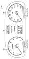
ステップS103では、表示制御部78は、各透光表示部50a,50b及び各警告表示部40a,40bを、瞬間的に、重畳表示する。ステップS103の処理後、ステップS104へ移る。   In step S103, the display control unit 78 instantaneously superimposes and displays the translucent display units 50a and 50b and the warning display units 40a and 40b. After the process of step S103, the process proceeds to step S104.

ステップS104では、表示制御部78は、ステップS102にて決定された表示制御仕様に基づいて、各透光表示部50a,50bの車両の状態の表示を開始し、継続する(図12参照)。ステップS104の処理後、ステップS105へ移る。   In step S104, the display control unit 78 starts displaying the vehicle state of each of the translucent display units 50a and 50b based on the display control specifications determined in step S102 (see FIG. 12). After the process of step S104, the process proceeds to step S105.

ステップS105では、表示制御部78は、車両の特定箇所の異常を示す異常情報が入力されなくなると、各警告表示部40a,40bの各警告灯42に点灯表示すべき警告灯42が存在しているか否かを判定する。ステップS105にて否定判定が下された場合、ステップS104へ戻る。ステップS105にて肯定判定が下された場合、ステップS106へ移る。   In step S105, when the abnormality information indicating an abnormality in a specific part of the vehicle is not input, the display control unit 78 has a warning light 42 to be lit and displayed on each warning light 42 of each warning display unit 40a, 40b. It is determined whether or not. If a negative determination is made in step S105, the process returns to step S104. If a positive determination is made in step S105, the process proceeds to step S106.

ステップS106では、表示制御部78は、点灯表示すべき警告灯42を点灯させて、警告の表示を開始する。これと共に、各透光表示部50a,50bのうち、点灯した警告灯42が属する警告表示部40a又は40bに対応する透光表示部50a又は50bを、一時的に消灯する。警告表示部40a,40bの両方に点灯表示する警告灯42が存在する場合には、透光表示部50a,50bの両方を、一時的に消灯する(図13参照)。透光表示部50a,50bの一時的な消灯は、1〜3秒程度の所定時間継続され、その後、ステップS107へ移る。   In step S106, the display control unit 78 turns on the warning lamp 42 to be turned on and starts displaying the warning. At the same time, among the translucent display sections 50a and 50b, the translucent display section 50a or 50b corresponding to the warning display section 40a or 40b to which the lit warning lamp 42 belongs is temporarily turned off. When there is a warning lamp 42 that is lit and displayed on both the warning display sections 40a and 40b, both the translucent display sections 50a and 50b are temporarily turned off (see FIG. 13). Temporary extinction of the translucent display portions 50a and 50b is continued for a predetermined time of about 1 to 3 seconds, and then the process proceeds to step S107.

ステップS107では、表示制御部78は、ステップS106にて点灯を開始した警告灯42について、警告の表示を継続させつつ、一時的に消灯していた透光表示部50a又は50bを点灯表示させて、警告表示部40a又は40bとこれに対応する透光表示部50a又は50bとを重畳表示する(図14参照)。ステップS107の処理後、再びステップS105に移る。   In step S107, the display control unit 78 causes the translucent display unit 50a or 50b, which has been temporarily turned off, to be lit on and displayed on the warning lamp 42 that has started to be turned on in step S106. The warning display section 40a or 40b and the corresponding translucent display section 50a or 50b are displayed in a superimposed manner (see FIG. 14). After the process of step S107, the process proceeds to step S105 again.

すなわち、ステップS105からステップS107の処理を繰り返すことにより、警告表示部40a又は40bの警告灯42の警告が表示されている間には、対応する透光表示部50a又は50bの表示内容は点滅しているように視認される。   That is, by repeating the processing from step S105 to step S107, the display content of the corresponding translucent display unit 50a or 50b flashes while the warning of the warning lamp 42 of the warning display unit 40a or 40b is displayed. Is visually recognized.

そして、車両の特定箇所の異常を示す異常情報が入力されなくなると、すなわち、異常が解消されて警告の表示が不要になると、ステップS105で否定判定されることとなるので、今度はステップS104とステップS105の処理が繰り返されることとなる。したがって、透光表示部50a,50bの表示内容のみが継続的に表示され、警告表示部40a,40bの警告は、非表示状態となる。   When abnormality information indicating an abnormality in a specific part of the vehicle is not input, that is, when the abnormality is resolved and the display of a warning is not required, a negative determination is made in step S105. The process of step S105 will be repeated. Therefore, only the display contents of the translucent display parts 50a and 50b are continuously displayed, and the warnings of the warning display parts 40a and 40b are not displayed.

なお、各図において、目盛67a等の複数設けられた要素には、その一部にのみ符号が付されている。   In each drawing, a plurality of elements such as the scale 67a are provided with reference numerals only for a part thereof.

(作用効果)
以上説明した本実施形態の作用効果を以下に説明する。
(Function and effect)
The operational effects of the present embodiment described above will be described below.

本実施形態によると、透光表示部50a,50bは、透光板52において、警告の表示と重畳する領域SPa,SPbに警告表示部40a,40bとは別の表示内容を点灯表示する。ここで、警告の表示を透過させる透光板52は、警告表示部40a,40bよりも視認側に配置されているので、警告の表示は、透光表示部50a,50bの表示内容よりも奥に表示されることとなり、立体感を演出できる。そして、通常時に点灯表示されている透光表示部50a,50bの表示内容は、警告表示部40a,40bにて警告を表示する場合に、一時的に消灯される。透光表示部50a,50bの表示内容が消えることで、警告の表示が視認し易くなるだけでなく、消灯による表示の変化によって警告の表示が目立つため、視認者の注目を集め易くなる。以上により、立体感を向上すると共に、視認性良好に警告を表示することで、視認者が警告を認識し易い車両用表示装置100を提供することができる。   According to the present embodiment, the translucent display units 50a and 50b light-display the display content different from the warning display units 40a and 40b in the areas SPa and SPb overlapping the display of the warning on the translucent plate 52. Here, since the translucent plate 52 that transmits the warning display is arranged on the viewing side with respect to the warning display units 40a and 40b, the display of the warning is deeper than the display contents of the translucent display units 50a and 50b. Will be displayed, and a three-dimensional effect can be produced. The display contents of the translucent display portions 50a and 50b that are normally turned on are temporarily turned off when a warning is displayed on the warning display portions 40a and 40b. The disappearance of the display contents of the translucent display portions 50a and 50b not only makes the warning display easy to see, but also makes the warning display conspicuous due to the change in the display caused by turning off the light. As described above, the display device 100 for a vehicle in which the viewer can easily recognize the warning can be provided by improving the stereoscopic effect and displaying the warning with good visibility.

また、本実施形態によると、警告表示部40a,40bの警告が表示されている間、透光表示部50a,50bの表示内容が点滅する。このようにすると、点滅により警告の表示に注目が行き易くなると共に、透光表示部50a,50bの表示内容が全く認識できなくなる事態も回避することができる。   Moreover, according to this embodiment, while the warning of the warning display parts 40a and 40b is displayed, the display content of the translucent display parts 50a and 50b blinks. This makes it easy to pay attention to the warning display by blinking, and avoids the situation where the display contents of the translucent display portions 50a and 50b cannot be recognized at all.

また、本実施形態によると、両表示部40a,40b及び50a,50bの表示色が互いに異なるので、両表示の区別が付き易くなり、視認性が高まる。   Further, according to the present embodiment, since the display colors of the display units 40a, 40b and 50a, 50b are different from each other, it is easy to distinguish both displays, and visibility is improved.

また、本実施形態によると、透光表示部50a,50bにおける表示内容の点灯表示は、透光板52の内部に光を提供する光源部58からの光を視認側に反射する反射部54により実現されている。こうした表示内容の点灯表示では、斬新な見栄えにより、警告の表示との立体感は一層高まる。そして、斬新な見栄えの表示内容が視認者の注目を引き付けつつ、警告表示部40a,40bにて警告を表示する場合に消灯するので、警告の表示の誘目性も一層高まるのである。   Further, according to the present embodiment, the lighting display of the display contents in the translucent display units 50a and 50b is performed by the reflecting unit 54 that reflects the light from the light source unit 58 that provides light to the inside of the translucent plate 52 to the viewing side. It has been realized. In the lighting display of such display contents, the three-dimensional effect with the warning display is further enhanced due to a novel appearance. And since the display content of a novel appearance attracts the viewer's attention, it is turned off when a warning is displayed on the warning display units 40a and 40b, so that the attractiveness of the warning display is further enhanced.

また、本実施形態によると、透光表示部50a,50bの表示内容として、目盛図柄67の目盛67aの一部又は全部が点灯表示されることにより、車両の状態が表示される。警告表示部40a,40bの警告の表示と重畳した領域SPa,SPbにおいて警告とは別の車両の状態を表示することにより、表示スペースが節約できる。   Moreover, according to this embodiment, the state of a vehicle is displayed by light-displaying a part or all of the scale 67a of the scale symbol 67 as display contents of the translucent display parts 50a and 50b. By displaying the vehicle state different from the warning in the areas SPa and SPb superimposed on the warning display of the warning display units 40a and 40b, the display space can be saved.

また、本実施形態によると、透光表示部50a,50bは、互いに隣り合って配置された発光素子58aの間に、各発光素子58aを区画する遮光性の遮光区画部60を有する。このようにすると、互いに隣り合って配置された発光素子58aから発せられる光が互いに混ざり合うことが防止されるので、各発光素子58aに個別に対応する目盛67aを独立して発光させることは、容易に実現可能となる。   In addition, according to the present embodiment, the translucent display units 50a and 50b include the light-shielding light-blocking partition 60 that partitions each light-emitting element 58a between the light-emitting elements 58a that are arranged adjacent to each other. In this way, light emitted from the light emitting elements 58a arranged adjacent to each other is prevented from being mixed with each other, so that each of the light emitting elements 58a can independently emit light corresponding to the scale 67a. It can be easily realized.

(他の実施形態)
以上、本発明の一実施形態について説明したが、本発明は、当該実施形態に限定して解釈されるものではなく、本発明の要旨を逸脱しない範囲内において種々の実施形態に適用することができる。
(Other embodiments)
Although one embodiment of the present invention has been described above, the present invention is not construed as being limited to the embodiment, and can be applied to various embodiments without departing from the gist of the present invention. it can.

具体的に、変形例1としては、透光表示部50a,50bは、目盛図柄67以外の表示内容を表示するものであってもよい。例えば表示内容として、車両の状態を示すマーク、加飾のための模様等が採用されてもよい。   Specifically, as a first modification, the translucent display units 50 a and 50 b may display display contents other than the scale symbol 67. For example, as a display content, a mark indicating the state of the vehicle, a pattern for decoration, or the like may be employed.

変形例2としては、透光表示部50a,50bは、光源部58からの光を反射する反射部54により、表示内容を表示するものでなくてもよい。例えば、透光板52として、有機ELディスプレイを採用し、当該有機ELディスプレイにより、表示内容が表示されてもよい。   As a second modification, the translucent display units 50 a and 50 b may not display the display content by the reflection unit 54 that reflects the light from the light source unit 58. For example, an organic EL display may be adopted as the translucent plate 52, and display content may be displayed by the organic EL display.

変形例3としては、警告表示部40a,40bは、表示板18に印刷された警告灯42を点灯させて警告を表示するものでなくてもよい。例えば、警告表示部40a,40bは、液晶パネル又は有機ELディスプレイの画像によって警告を表示してもよい。   As a third modification, the warning display units 40 a and 40 b do not have to display the warning by turning on the warning lamp 42 printed on the display board 18. For example, the warning display units 40a and 40b may display a warning with an image of a liquid crystal panel or an organic EL display.

変形例4としては、表示制御部78は、警告表示部40a,40bの警告が表示されている間、透光表示部50a,50bの表示内容を消灯し続けるようにしてもよい。   As a fourth modification, the display control unit 78 may continue to turn off the display contents of the translucent display units 50a and 50b while the warnings of the warning display units 40a and 40b are displayed.

100 車両用表示装置、40a,40b 警告表示部、50a,50b 透光表示部、52 透光板、78 表示制御部、SPa,SPb 警告の表示と重畳する領域   DESCRIPTION OF SYMBOLS 100 Display apparatus for vehicles, 40a, 40b Warning display part, 50a, 50b Translucent display part, 52 Translucent board, 78 Display control part, SPa, SPb The area | region which overlaps with a warning display

Claims (4)

車両に搭載される車両用表示装置であって、
警告を表示可能に形成された警告表示部(40a,40b)と、
前記警告表示部よりも視認側に配置され、前記警告の表示を透過させる透光板(52)を有し、前記透光板において、前記警告の表示と重畳する領域(SPa,SPb)に前記警告表示部とは別の表示内容を通常時に点灯表示する透光表示部(50a,50b)と、
前記警告表示部及び前記透光表示部の表示を制御する表示制御部(78)と、を備え、
前記表示制御部は、前記警告表示部の前記警告を表示する場合に、前記透光表示部の前記表示内容を一時的に消灯させ
前記透光表示部は、
前記透光板の内部に光を提供する光源部(58)と、
前記透光板に形成され、前記光源部からの前記光を視認側に反射することにより、前記表示内容を点灯表示する反射部(54)と、を有し、
前記反射部は、前記透光板の外縁部に沿って配列された複数の目盛(67a)を含む目盛図柄(67)を、前記表示内容として有し、
前記光源部は、各前記目盛に個別に対応する複数の発光素子(58a)を有し、
前記表示制御部は、各前記発光素子の点灯及び消灯を個別に制御することにより、前記目盛図柄の目盛の一部又は全部を点灯表示させて、前記車両の状態を表示させる車両用表示装置。
A vehicle display device mounted on a vehicle,
Warning display portions (40a, 40b) formed so as to be able to display warnings;
It has a translucent plate (52) that is arranged on the viewer side of the warning display part and transmits the display of the warning, and in the translucent plate, the region (SPa, SPb) that overlaps the display of the warning A translucent display unit (50a, 50b) that displays a display content different from the warning display unit in a normal state;
A display control unit (78) for controlling display of the warning display unit and the translucent display unit,
The display control unit, when displaying the warning of the warning display unit, temporarily turns off the display content of the translucent display unit ,
The translucent display part is
A light source unit (58) for providing light to the inside of the translucent plate;
A reflection part (54) that is formed on the translucent plate and reflects the light from the light source part to the viewing side to turn on and display the display content;
The reflection part has a scale symbol (67) including a plurality of scales (67a) arranged along an outer edge part of the translucent plate as the display content,
The light source unit includes a plurality of light emitting elements (58a) individually corresponding to the scales,
The said display control part is a vehicle display apparatus which displays the state of the said vehicle by carrying out the lighting display of a part or all of the scale of the said scale symbol by controlling lighting and light extinction of each said light emitting element separately .
前記表示制御部は、前記警告表示部の前記警告が表示されている間、前記透光表示部の前記表示内容を点滅させる請求項1に記載の車両用表示装置。   The vehicle display device according to claim 1, wherein the display control unit blinks the display content of the translucent display unit while the warning of the warning display unit is displayed. 前記透光表示部の前記表示内容の表示色は、前記警告表示部の前記警告の表示色と異なる請求項1又は2に記載の車両用表示装置。   3. The vehicle display device according to claim 1, wherein a display color of the display content of the translucent display unit is different from a display color of the warning of the warning display unit. 前記透光表示部は、互いに隣り合って配置された前記発光素子の間に、各前記発光素子を区画する遮光性の遮光区画部(60)を有する請求項1から請求項3のいずれか1項に記載の車両用表示装置。 The light transmission display part is between each other and arranged above the light emitting elements adjacent to each other, any one of claims 1 to 3 having a light-shielding property of the light-shielding partition part for partitioning each said light emitting element (60) The vehicle display device according to the item .
JP2017010424A 2016-11-08 2017-01-24 Vehicle display device Expired - Fee Related JP6597656B2 (en)

Priority Applications (6)

Application Number Priority Date Filing Date Title
JP2017010424A JP6597656B2 (en) 2017-01-24 2017-01-24 Vehicle display device
CN201780069971.3A CN109964101B (en) 2016-11-08 2017-09-14 Display device for vehicle
DE112017005615.2T DE112017005615T5 (en) 2016-11-08 2017-09-14 DISPLAY DEVICE FOR A VEHICLE
KR1020197010715A KR102277852B1 (en) 2016-11-08 2017-09-14 vehicle display device
PCT/JP2017/033185 WO2018088024A1 (en) 2016-11-08 2017-09-14 Vehicular display device
US16/395,314 US11117468B2 (en) 2016-11-08 2019-04-26 Display device for vehicle

Applications Claiming Priority (1)

Application Number Priority Date Filing Date Title
JP2017010424A JP6597656B2 (en) 2017-01-24 2017-01-24 Vehicle display device

Publications (2)

Publication Number Publication Date
JP2018118581A JP2018118581A (en) 2018-08-02
JP6597656B2 true JP6597656B2 (en) 2019-10-30

Family

ID=63044273

Family Applications (1)

Application Number Title Priority Date Filing Date
JP2017010424A Expired - Fee Related JP6597656B2 (en) 2016-11-08 2017-01-24 Vehicle display device

Country Status (1)

Country Link
JP (1) JP6597656B2 (en)

Family Cites Families (7)

* Cited by examiner, † Cited by third party
Publication number Priority date Publication date Assignee Title
JPS5539284Y2 (en) * 1975-04-30 1980-09-13
JP2002156251A (en) * 2000-11-17 2002-05-31 Denso Corp Gauge for vehicle
JP5132016B2 (en) * 2000-12-26 2013-01-30 矢崎総業株式会社 Meter structure
JP2009186400A (en) * 2008-02-08 2009-08-20 Calsonic Kansei Corp Lighting structure of instrument for vehicle
JP5796475B2 (en) * 2011-11-30 2015-10-21 日本精機株式会社 Instrument device
JP6498995B2 (en) * 2014-05-19 2019-04-10 矢崎総業株式会社 Vehicle display device
JP6478009B2 (en) * 2014-09-08 2019-03-06 株式会社デンソー Display device

Also Published As

Publication number Publication date
JP2018118581A (en) 2018-08-02

Similar Documents

Publication Publication Date Title
CN109964101B (en) Display device for vehicle
US7762703B2 (en) Heads-up display, motor vehicle and method of operating a heads-up display
US7750821B1 (en) System and method for instrument panel with color graphical display
JP4626710B2 (en) Vehicle display device
US7278748B2 (en) Display apparatus
US20060158320A1 (en) Display device having decorative member on screen
JP2007071540A (en) Display device for vehicle
JP5083498B2 (en) Lighting device
JP6798266B2 (en) Display device
US10513182B2 (en) Vehicle display apparatus
JP2007121822A (en) Display device
JP6597656B2 (en) Vehicle display device
US10266054B2 (en) Vehicle display device
JP4881860B2 (en) Indicator with screen illuminated by suppressed light and warning light
US20120087149A1 (en) Ultra-thin light guide for cluster gauge illumination over display structures
KR20050028300A (en) Combination meter for cars
JP2003329491A (en) Pointer type measuring instrument
JP6615156B2 (en) Vehicle display device
JP4199383B2 (en) Instrument display
JP2001066166A (en) Display device for measuring instrument
JP2005300359A (en) Display device for vehicle
US20040189446A1 (en) Vehicle dashboard
US10807472B2 (en) Vehicular display device
EP3393841B1 (en) Vehicle instrument cluster provided with a monochromatic display
JP2003329964A (en) Display device

Legal Events

Date Code Title Description
A621 Written request for application examination

Free format text: JAPANESE INTERMEDIATE CODE: A621

Effective date: 20180913

A131 Notification of reasons for refusal

Free format text: JAPANESE INTERMEDIATE CODE: A131

Effective date: 20190528

A521 Request for written amendment filed

Free format text: JAPANESE INTERMEDIATE CODE: A523

Effective date: 20190719

TRDD Decision of grant or rejection written
A01 Written decision to grant a patent or to grant a registration (utility model)

Free format text: JAPANESE INTERMEDIATE CODE: A01

Effective date: 20190903

A61 First payment of annual fees (during grant procedure)

Free format text: JAPANESE INTERMEDIATE CODE: A61

Effective date: 20190916

R151 Written notification of patent or utility model registration

Ref document number: 6597656

Country of ref document: JP

Free format text: JAPANESE INTERMEDIATE CODE: R151

LAPS Cancellation because of no payment of annual fees