JP6597461B2 - Amplifier circuit - Google Patents
Amplifier circuit Download PDFInfo
- Publication number
- JP6597461B2 JP6597461B2 JP2016079139A JP2016079139A JP6597461B2 JP 6597461 B2 JP6597461 B2 JP 6597461B2 JP 2016079139 A JP2016079139 A JP 2016079139A JP 2016079139 A JP2016079139 A JP 2016079139A JP 6597461 B2 JP6597461 B2 JP 6597461B2
- Authority
- JP
- Japan
- Prior art keywords
- switching circuit
- circuit
- input
- amplifier
- output terminal
- Prior art date
- Legal status (The legal status is an assumption and is not a legal conclusion. Google has not performed a legal analysis and makes no representation as to the accuracy of the status listed.)
- Active
Links
Images


Classifications
-
- H—ELECTRICITY
- H03—ELECTRONIC CIRCUITRY
- H03F—AMPLIFIERS
- H03F1/00—Details of amplifiers with only discharge tubes, only semiconductor devices or only unspecified devices as amplifying elements
- H03F1/56—Modifications of input or output impedances, not otherwise provided for
- H03F1/565—Modifications of input or output impedances, not otherwise provided for using inductive elements
-
- H—ELECTRICITY
- H03—ELECTRONIC CIRCUITRY
- H03F—AMPLIFIERS
- H03F1/00—Details of amplifiers with only discharge tubes, only semiconductor devices or only unspecified devices as amplifying elements
- H03F1/02—Modifications of amplifiers to raise the efficiency, e.g. gliding Class A stages, use of an auxiliary oscillation
- H03F1/0205—Modifications of amplifiers to raise the efficiency, e.g. gliding Class A stages, use of an auxiliary oscillation in transistor amplifiers
- H03F1/0261—Modifications of amplifiers to raise the efficiency, e.g. gliding Class A stages, use of an auxiliary oscillation in transistor amplifiers with control of the polarisation voltage or current, e.g. gliding Class A
-
- H—ELECTRICITY
- H03—ELECTRONIC CIRCUITRY
- H03F—AMPLIFIERS
- H03F1/00—Details of amplifiers with only discharge tubes, only semiconductor devices or only unspecified devices as amplifying elements
- H03F1/02—Modifications of amplifiers to raise the efficiency, e.g. gliding Class A stages, use of an auxiliary oscillation
- H03F1/0205—Modifications of amplifiers to raise the efficiency, e.g. gliding Class A stages, use of an auxiliary oscillation in transistor amplifiers
- H03F1/0211—Modifications of amplifiers to raise the efficiency, e.g. gliding Class A stages, use of an auxiliary oscillation in transistor amplifiers with control of the supply voltage or current
-
- H—ELECTRICITY
- H03—ELECTRONIC CIRCUITRY
- H03F—AMPLIFIERS
- H03F1/00—Details of amplifiers with only discharge tubes, only semiconductor devices or only unspecified devices as amplifying elements
- H03F1/56—Modifications of input or output impedances, not otherwise provided for
-
- H—ELECTRICITY
- H03—ELECTRONIC CIRCUITRY
- H03F—AMPLIFIERS
- H03F3/00—Amplifiers with only discharge tubes or only semiconductor devices as amplifying elements
- H03F3/189—High frequency amplifiers, e.g. radio frequency amplifiers
- H03F3/19—High frequency amplifiers, e.g. radio frequency amplifiers with semiconductor devices only
- H03F3/195—High frequency amplifiers, e.g. radio frequency amplifiers with semiconductor devices only in integrated circuits
-
- H—ELECTRICITY
- H03—ELECTRONIC CIRCUITRY
- H03F—AMPLIFIERS
- H03F3/00—Amplifiers with only discharge tubes or only semiconductor devices as amplifying elements
- H03F3/72—Gated amplifiers, i.e. amplifiers which are rendered operative or inoperative by means of a control signal
-
- H—ELECTRICITY
- H03—ELECTRONIC CIRCUITRY
- H03F—AMPLIFIERS
- H03F2200/00—Indexing scheme relating to amplifiers
- H03F2200/111—Indexing scheme relating to amplifiers the amplifier being a dual or triple band amplifier, e.g. 900 and 1800 MHz, e.g. switched or not switched, simultaneously or not
-
- H—ELECTRICITY
- H03—ELECTRONIC CIRCUITRY
- H03F—AMPLIFIERS
- H03F2200/00—Indexing scheme relating to amplifiers
- H03F2200/222—A circuit being added at the input of an amplifier to adapt the input impedance of the amplifier
-
- H—ELECTRICITY
- H03—ELECTRONIC CIRCUITRY
- H03F—AMPLIFIERS
- H03F2200/00—Indexing scheme relating to amplifiers
- H03F2200/294—Indexing scheme relating to amplifiers the amplifier being a low noise amplifier [LNA]
-
- H—ELECTRICITY
- H03—ELECTRONIC CIRCUITRY
- H03F—AMPLIFIERS
- H03F2200/00—Indexing scheme relating to amplifiers
- H03F2200/387—A circuit being added at the output of an amplifier to adapt the output impedance of the amplifier
-
- H—ELECTRICITY
- H03—ELECTRONIC CIRCUITRY
- H03F—AMPLIFIERS
- H03F2203/00—Indexing scheme relating to amplifiers with only discharge tubes or only semiconductor devices as amplifying elements covered by H03F3/00
- H03F2203/72—Indexing scheme relating to gated amplifiers, i.e. amplifiers which are rendered operative or inoperative by means of a control signal
- H03F2203/7209—Indexing scheme relating to gated amplifiers, i.e. amplifiers which are rendered operative or inoperative by means of a control signal the gated amplifier being switched from a first band to a second band
-
- H—ELECTRICITY
- H03—ELECTRONIC CIRCUITRY
- H03F—AMPLIFIERS
- H03F2203/00—Indexing scheme relating to amplifiers with only discharge tubes or only semiconductor devices as amplifying elements covered by H03F3/00
- H03F2203/72—Indexing scheme relating to gated amplifiers, i.e. amplifiers which are rendered operative or inoperative by means of a control signal
- H03F2203/7233—Indexing scheme relating to gated amplifiers, i.e. amplifiers which are rendered operative or inoperative by means of a control signal the gated amplifier, switched on or off by putting into parallel or not, by choosing between amplifiers by one or more switch(es), being impedance adapted by switching an adapted passive network
-
- H—ELECTRICITY
- H03—ELECTRONIC CIRCUITRY
- H03F—AMPLIFIERS
- H03F2203/00—Indexing scheme relating to amplifiers with only discharge tubes or only semiconductor devices as amplifying elements covered by H03F3/00
- H03F2203/72—Indexing scheme relating to gated amplifiers, i.e. amplifiers which are rendered operative or inoperative by means of a control signal
- H03F2203/7236—Indexing scheme relating to gated amplifiers, i.e. amplifiers which are rendered operative or inoperative by means of a control signal the gated amplifier being switched on or off by putting into parallel or not, by choosing between amplifiers by (a ) switch(es)
-
- H—ELECTRICITY
- H03—ELECTRONIC CIRCUITRY
- H03F—AMPLIFIERS
- H03F2203/00—Indexing scheme relating to amplifiers with only discharge tubes or only semiconductor devices as amplifying elements covered by H03F3/00
- H03F2203/72—Indexing scheme relating to gated amplifiers, i.e. amplifiers which are rendered operative or inoperative by means of a control signal
- H03F2203/7239—Indexing scheme relating to gated amplifiers, i.e. amplifiers which are rendered operative or inoperative by means of a control signal the gated amplifier being switched on or off by putting into parallel or not, by choosing between amplifiers and shunting lines by one or more switch(es)
Description
本発明は、増幅回路に関し、特に、入力信号を増幅器に入力させることと増幅器をバイパスさせることとを選択的に行う増幅回路に関する。 The present invention relates to an amplifier circuit, and more particularly, to an amplifier circuit that selectively inputs an input signal to an amplifier and bypasses the amplifier.
アンテナ等で受信された入力信号の増幅回路として、入力信号が小電力の信号である場合には信号を低雑音増幅器に入力させて増幅し、入力信号が大電力の信号である場合には低雑音増幅器をバイパスさせる処理が行われるものがある。 As an amplifying circuit for an input signal received by an antenna or the like, when the input signal is a low power signal, the signal is input to a low noise amplifier to be amplified, and when the input signal is a high power signal, the signal is low. Some processes bypass the noise amplifier.
従来、このような低雑音増幅とバイパスとを選択的に行うバイパス回路付き増幅回路として、様々なものが提案されている(例えば、特許文献1)。 Conventionally, various types of amplifier circuits with bypass circuits that selectively perform such low noise amplification and bypass have been proposed (for example, Patent Document 1).
特許文献1には、低雑音増幅性能を維持しつつ、利得制御状態の如何にかかわらず入出力のインピーダンスの整合を図るために、入力整合回路と出力整合回路との間に接続された低雑音増幅器(以下「増幅器」と記す)と、増幅器に並列に接続されたバイパス回路とを含む可変利得増幅回路が開示されている。この可変利得増幅回路では、高利得モードの選択時において出力整合回路が増幅器の出力側のインピーダンスを整合させ、低利得モードの選択時において整合補正回路が出力整合回路に並列に接続され、バイパス回路の出力側のインピーダンスを整合させる。
特許文献1の可変利得増幅回路によって、入力信号が低電力の信号である場合には入力信号を増幅器に入力させて増幅し、入力信号が大電力の信号である場合には増幅器をバイパスさせることもできる。
With the variable gain amplifier circuit of
しかしながら、特許文献1の可変利得増幅回路では、バイパス時には、入力信号は入力整合回路の周波数特性の影響を受けるために、広い周波数帯域にわたる入力信号(つまり、複数の周波数帯域の入力信号)を扱うには、通過特性の周波数依存性が大きいという問題がある。つまり、入力整合回路は、可変利得増幅回路の入力側のインピーダンスを整合させるために設けられるが、バイパス時には、入力信号は、入力整合回路を通った後に、増幅器に入力されずにバイパス回路に入力される。そのために、バイパス時には、入力整合回路の通過帯域から外れた周波数の入力信号については、その周波数に対応する通過損失が発生する。その結果、入力信号の周波数に依存して、発生する通過損失が異なり、複数の周波数帯域の入力信号を扱う受信回路として使用するのが困難となる。
However, in the variable gain amplifier circuit of
また、特許文献1の可変利得増幅回路では、バイパス時には、増幅器の動作がオフしているものの、バイパス回路と増幅器の入力端子とが並列に接続されているので、入力信号は増幅器の入力インピーダンスによる周波数特性の影響も受ける。そのために、入力信号の周波数に依存して、通過損失の違いがさらに大きくなるという問題もある。
Further, in the variable gain amplifier circuit of
ここで、バイパス時における通過特性の周波数依存性を改善するために入力整合回路を変更することも考えられる(例えば、入力整合回路そのものを変更したり、入力回路を構成する素子の数を変更したり、素子自体を変更したり、素子の定数値を変更したりなど)。しかしながら、そのような変更をしたのでは、入力整合回路は、増幅器に対する最適な入力整合回路ではなくなる。その結果、入力信号を増幅器で増幅する場合における特性(通過特性の周波数依存性)が確保されなくなる。 Here, it is conceivable to change the input matching circuit in order to improve the frequency dependence of the pass characteristics during bypassing (for example, changing the input matching circuit itself or changing the number of elements constituting the input circuit). Or changing the element itself, or changing the constant value of the element). However, with such changes, the input matching circuit is no longer the optimum input matching circuit for the amplifier. As a result, characteristics (frequency dependence of pass characteristics) when an input signal is amplified by an amplifier cannot be ensured.
そこで、本発明は、従来よりもバイパス時の周波数依存性が抑制されたバイパス経路付き増幅回路を提供することを目的とする。 Therefore, an object of the present invention is to provide an amplifying circuit with a bypass path in which the frequency dependency during bypass is suppressed more than in the prior art.
上記目的を達成するために、本発明に係る増幅回路の一形態は、複数の周波数帯域に対応した複数の入力端子、第1出力端子及び第2出力端子を有し、前記第1出力端子を前記複数の入力端子のいずれかに選択的に接続状態にしながら、前記第2出力端子を前記複数の入力端子のいずれに対しても開放状態にするか、前記第1出力端子を前記複数の入力端子のいずれに対しても開放状態にしながら、前記第2出力端子を前記複数の入力端子のいずれかに選択的に接続状態にする第1切替回路と、前記第1出力端子に接続された整合回路と、前記整合回路の出力側に接続された増幅器と、前記増幅器の出力側に接続され、前記第1切替回路が前記第1出力端子を開放状態にするとともに前記第2出力端子を前記複数の入力端子のいずれかに選択的に接続した場合に非導通状態になる第2切替回路と、前記第2出力端子と前記第2切替回路の出力端子とを電気的に接続するバイパス経路とを備える。 In order to achieve the above object, one embodiment of an amplifier circuit according to the present invention has a plurality of input terminals corresponding to a plurality of frequency bands, a first output terminal, and a second output terminal, and the first output terminal is While selectively connecting to any of the plurality of input terminals, the second output terminal is opened to any of the plurality of input terminals, or the first output terminal is set to the plurality of inputs. A first switching circuit for selectively connecting the second output terminal to any one of the plurality of input terminals while keeping an open state with respect to any of the terminals; and a matching connected to the first output terminal A circuit, an amplifier connected to an output side of the matching circuit, and an output side of the amplifier, wherein the first switching circuit opens the first output terminal and the second output terminal includes the plurality of second output terminals. Select one of the input terminals Comprising a second switching circuit comprising a non-conductive state, and a bypass path for electrically connecting the second output terminal and the output terminal of said second switching circuit when connected to.
これにより、第1切替回路に入力された信号は、バイパス時(第1切替回路において、第1出力端子を開放状態にするとともに第2出力端子を複数の入力端子のいずれかに選択的に接続した時)には、整合回路とは切り離された第2出力端子及びバイパス経路を経て出力される。つまり、バイパス時には、入力信号は、増幅器の入力側に接続された整合回路を通過しないので、整合回路の周波数特性の影響を受けることが抑制される。 As a result, the signal input to the first switching circuit is bypassed (in the first switching circuit, the first output terminal is opened and the second output terminal is selectively connected to one of the plurality of input terminals). Output) via the second output terminal and the bypass path separated from the matching circuit. That is, at the time of bypassing, the input signal does not pass through the matching circuit connected to the input side of the amplifier, so that the influence of the frequency characteristics of the matching circuit is suppressed.
また、増幅器の出力側には、第2切替回路が設けられ、バイパス時に第2切替回路がオフ(非導通状態)になるので、バイパス経路を通過する入力信号は、増幅器の出力インピーダンスの周波数特性の影響を受けることも抑制される。 In addition, since the second switching circuit is provided on the output side of the amplifier and the second switching circuit is turned off (non-conducting state) at the time of bypassing, the input signal passing through the bypass path has a frequency characteristic of the output impedance of the amplifier. It is suppressed that it is influenced by.
さらに、整合回路は、増幅器に接続されており、バイパス経路に接続されることがないので、増幅器に対して最適な整合回路となるように設計すれば済む。 Further, since the matching circuit is connected to the amplifier and is not connected to the bypass path, the matching circuit may be designed to be an optimum matching circuit for the amplifier.
以上のことから、従来よりもバイパス時における周波数依存性が抑制されたバイパス経路付き増幅回路が実現される。 From the above, an amplifier circuit with a bypass path in which the frequency dependency during bypass is suppressed more than in the prior art is realized.
ここで、前記第1切替回路及び前記第2切替回路は、一つの半導体基板上に形成されてもよい。 Here, the first switching circuit and the second switching circuit may be formed on a single semiconductor substrate.
これにより、第1切替回路及び第2切替回路が一つのICパッケージに組み込まれるので、部品の実装面積が削減され、低コスト化がはかられる。 Thereby, since the first switching circuit and the second switching circuit are incorporated in one IC package, the mounting area of the components is reduced, and the cost can be reduced.
また、前記増幅回路はさらに、入力端子及び複数の出力端子を有し、前記入力端子を前記複数の出力端子のいずれかに選択的に接続する第3切替回路と、前記第3切替回路が有する前記複数の出力端子に1対1対応で接続された複数のフィルタとを備え、前記第1切替回路が有する前記複数の入力端子は、前記複数のフィルタの出力端子に1対1対応で接続されてもよい。 Also, before Symbol amplifier circuit further comprises an input terminal and a plurality of output terminals, a third switching circuit for selectively connecting said input terminal to one of said plurality of output terminals, said third switching circuit A plurality of filters connected to the plurality of output terminals in a one-to-one correspondence, and the plurality of input terminals included in the first switching circuit correspond to the output terminals of the plurality of filters in a one-to-one correspondence. It may be connected.
これにより、第1切替回路と第3切替回路とを連動させて切り替えることで、入力信号を複数のフィルタのいずれかに選択的に通過させ、必要な周波数帯域の信号だけを取り出して増幅又はバイパス経路を通過させることを選択的に行うことができる。 As a result, by switching the first switching circuit and the third switching circuit in conjunction with each other, the input signal is selectively passed through one of the plurality of filters, and only the signal in the necessary frequency band is extracted and amplified or bypassed. Passing the route can be performed selectively.
また、前記第1切替回路及び前記第2切替回路は、一つの半導体基板上に形成されてもよい。 The first switching circuit and the second switching circuit may be formed on a single semiconductor substrate.
これにより、第1切替回路及び第2切替回路が一つのICパッケージに組み込まれるので、部品の実装面積が削減され、低コスト化がはかられる。 Thereby, since the first switching circuit and the second switching circuit are incorporated in one IC package, the mounting area of the components is reduced, and the cost can be reduced.
また、前記一つの半導体基板上には、さらに、前記第3切替回路も形成されてもよい。 In addition, the third switching circuit may be formed on the one semiconductor substrate.
これにより、第1切替回路及び第2切替回路に加えて、第3切替回路も同じICパッケージに組み込まれるので、さらに、部品の実装面積が削減され、低コスト化がはかられる。 Thereby, in addition to the first switching circuit and the second switching circuit, the third switching circuit is also incorporated in the same IC package, so that the mounting area of the components is further reduced and the cost can be reduced.
あるいは、前記第3切替回路は、前記一つの半導体基板とは別の半導体基板上に形成されてもよい。 Alternatively, the third switching circuit may be formed on a semiconductor substrate different from the one semiconductor substrate.
これにより、第3切替回路は、第1切替回路及び第2切替回路が形成される半導体基板とは別の半導体基板上に形成されるので、それぞれの半導体基板において最適な設計を行うことができ、設計の自由度が上がる。 As a result, the third switching circuit is formed on a different semiconductor substrate from the semiconductor substrate on which the first switching circuit and the second switching circuit are formed, so that the optimum design can be performed on each semiconductor substrate. , Design freedom increases.
また、前記増幅器は、前記第1切替回路及び前記第2切替回路が形成された前記一つの半導体基板上に形成されてもよい。 The amplifier may be formed on the one semiconductor substrate on which the first switching circuit and the second switching circuit are formed.
これにより、第1切替回路及び第2切替回路に加えて、増幅器も同じICパッケージに組み込まれるので、さらに、部品の実装面積が削減され、低コスト化がはかられる。 Thereby, in addition to the first switching circuit and the second switching circuit, the amplifier is also incorporated in the same IC package, so that the mounting area of the components is further reduced and the cost can be reduced.
また、さらに、前記第1切替回路及び前記第2切替回路を制御する制御回路を備え、前記制御回路は、前記第1切替回路が有する前記複数の入力端子の一つに入力された信号を増幅する場合には、前記第1切替回路において、前記第1出力端子を前記信号が入力されている前記複数の入力端子の一つに接続するとともに、前記第2出力端子を開放状態にするように、前記第1切替回路を制御し、かつ、前記第2切替回路を導通状態に制御し、前記第1切替回路が有する前記複数の入力端子の一つに入力された信号を増幅しない場合には、前記第1切替回路において、前記第1出力端子を開放状態にするとともに、前記第2出力端子を前記複数の入力端子の一つに接続するように、前記第1切替回路を制御し、かつ、前記第2切替回路を非導通状態に制御してもよい。 The control circuit further includes a control circuit that controls the first switching circuit and the second switching circuit, and the control circuit amplifies a signal input to one of the plurality of input terminals of the first switching circuit. In this case, in the first switching circuit, the first output terminal is connected to one of the plurality of input terminals to which the signal is input, and the second output terminal is opened. In the case where the first switching circuit is controlled, the second switching circuit is controlled to be in a conductive state, and the signal input to one of the plurality of input terminals of the first switching circuit is not amplified. And controlling the first switching circuit to open the first output terminal and connect the second output terminal to one of the plurality of input terminals in the first switching circuit, and , Non-conducting the second switching circuit It may be controlled in the state.
これにより、制御回路によって第1切替回路、第3切替回路及び第2切替回路が制御され、入力された信号を所望のフィルタに通過させることで、必要な周波数帯域の信号だけを取り出したうえで、信号の電力に応じて、増幅又通過させることを選択的に行うことができる。 Thereby, the first switching circuit, the third switching circuit, and the second switching circuit are controlled by the control circuit, and only the signal in the necessary frequency band is extracted by passing the input signal through a desired filter. Depending on the power of the signal, it can be selectively amplified or passed.
また、前記第1切替回路は、前記複数の入力端子に入力された信号を当該信号の周波数帯域に応じて選択的に出力するダイプレクサ又はトリプレクサを有してもよい。 The first switching circuit, the signal input before Symbol plurality of input terminals may have a diplexer or triplexer selectively outputs in accordance with the frequency band of the signal.
これにより、第1切替回路は、ダイプレクサ又はトリプレクサで構成されるので、外部からの制御信号を必要とすることなく、第1切替回路に入力された信号の周波数帯域に応じて切替(入力信号の選択)が行われる。 As a result, the first switching circuit is constituted by a diplexer or a triplexer, so that the switching (input signal of the input signal) can be performed according to the frequency band of the signal input to the first switching circuit without the need for an external control signal. Selection) is performed.
本発明により、バイパス時における周波数依存性が抑制されたバイパス経路付き増幅回路が実現される。 According to the present invention, an amplifying circuit with a bypass path in which frequency dependency during bypass is suppressed is realized.
以下、本発明の実施の形態について、図面を用いて詳細に説明する。なお、以下で説明する実施の形態は、いずれも本発明の一具体例を示すものである。以下の実施の形態で示される数値、形状、材料、構成要素、構成要素の配置位置及び接続形態、制御手順等は、一例であり、本発明を限定する主旨ではない。また、以下の実施の形態における構成要素のうち、本発明の最上位概念を示す独立請求項に記載されていない構成要素については、任意の構成要素として説明される。 Hereinafter, embodiments of the present invention will be described in detail with reference to the drawings. Note that each of the embodiments described below shows a specific example of the present invention. Numerical values, shapes, materials, constituent elements, arrangement positions and connection forms of constituent elements, control procedures, and the like shown in the following embodiments are merely examples, and are not intended to limit the present invention. In addition, among the constituent elements in the following embodiments, constituent elements that are not described in the independent claims indicating the highest concept of the present invention are described as optional constituent elements.
(実施の形態1)
図1は、本発明の実施の形態1における増幅回路10の回路図である。増幅回路10は、バイパス経路付き増幅回路であり、第1切替回路12、整合回路14、増幅器16、第2切替回路18及びバイパス経路19を備える。
(Embodiment 1)
FIG. 1 is a circuit diagram of an
第1切替回路12は、1以上の入力端子(ここでは、複数の周波数帯域の信号a〜gに対応した入力端子12a〜12g)、第1出力端子12i及び第2出力端子12hを有し、第1出力端子12iを入力端子12a〜12gのいずれかに選択的に接続状態にしながら、第2出力端子12hを入力端子12a〜12gのいずれに対しても開放状態にするか、入力端子12a〜12gのいずれに対しても開放状態にしながら、第2出力端子12hを入力端子12a〜12gのいずれかに選択的に接続状態にする回路であり、例えば、nPDT(n Pole Double Throw;nは入力端子(ここでは、周波数帯域)の数)の高周波スイッチで構成される合波器等である。なお、第1切替回路が1つの入力端子を有する場合とは、複数の周波数帯域の各バンド毎に1個の第1切替回路を設ける(つまり、バンドの数だけ第1切替回路を設ける)場合である。これにより、各バンド間のアイソレーション特性が向上可能である。
The
整合回路14は、第1切替回路12の第1出力端子12iに接続された入力整合回路であり、増幅器16の入力側のインピーダンスを整合させるために設けられ、コンデンサ及びインダクタ等を用いて構成される。
The matching
増幅器16は、整合回路14の出力側に接続された増幅器であり、例えば、Si−Geプロセスで製作される低雑音増幅器である。
The
第2切替回路18は、増幅器16の出力側に接続され、外部から入力される制御信号に従ってオン(導通状態)又はオフ(非導通状態)になるスイッチであり、例えば、SPST(Single Pole Single Throw)の高周波スイッチである。
The
バイパス経路19は、第1切替回路12の第2出力端子12hと第2切替回路18の出力端子とを電気的に接続する信号経路であり、例えば、基板上に形成される配線パターンである。
The
なお、本図の増幅回路10には、増幅回路10の出力側のインピーダンスを整合させるための出力整合回路が設けられていないが、必要な場合には、増幅器16と第2切替回路18との間に、出力整合回路を設けてもよい。
The
以上のように構成された本実施の形態における増幅回路10は、次のように動作する。
The
第1切替回路12の複数の入力端子12a〜12gの一つに入力された処理対象の信号が小電力の信号である(つまり、入力信号を増幅する)場合には、第1切替回路12及び第2切替回路18は、外部に設けられた制御回路(図示せず)からの制御信号に従って、次のように動作する。
When the signal to be processed input to one of the plurality of
つまり、第1切替回路12は、第1出力端子12iを処理対象の信号が入力されている入力端子12a〜12gの一つに接続するとともに、第2出力端子12hを開放状態にする。また、第2切替回路18は、オンになる。これによって、第1切替回路12の複数の入力端子12a〜12gの一つに入力された処理対象の信号は、バイパス経路19とは切り離された整合回路14を通過して増幅器16に入力され、増幅器16で増幅された後に第2切替回路18を通過して出力される。
That is, the
一方、第1切替回路12の複数の入力端子12a〜12gの一つに入力された処理対象の信号が大電力の信号である(つまり、入力信号を増幅しないでバイパス経路19を通過させる)場合には、第1切替回路12及び第2切替回路18は、外部に設けられた制御回路(図示せず)からの制御信号に従って、次のように動作する。
On the other hand, when the signal to be processed input to one of the plurality of
つまり、第1切替回路12は、第1出力端子12iを開放状態にするとともに、第2出力端子12hを、処理対象の信号が入力されている入力端子12a〜12gの一つに接続する。また、第2切替回路18は、オフになる。これによって、第1切替回路12の複数の入力端子12a〜12gの一つに入力された処理対象の信号は、整合回路14及び増幅器16とは切り離された第2出力端子12h及びバイパス経路19を経て出力される。
That is, the
このように、本実施の形態における増幅回路10によれば、第1切替回路12に入力された処理対象の信号は、バイパス時には、整合回路14とは切り離された(第1出力端子12i及び第2出力端子12h間のアイソレーションの分だけ絶縁された)第2出力端子12h及びバイパス経路19を経て出力される。つまり、バイパス時には、入力信号は、増幅器16の入力側に接続された整合回路14を通過しないので、整合回路14の周波数特性の影響を受けることが抑制される。
As described above, according to the
また、増幅器16の出力側には、第2切替回路18が設けられ、バイパス時に第2切替回路18がオフになるので、バイパス経路19を通過する入力信号は、増幅器16の出力インピーダンスの周波数特性の影響を受けることも抑制(第2切替回路18のオフ時におけるアイソレーションの分だけ抑制)される。
Further, the
さらに、整合回路14は、増幅器16に接続されており、バイパス経路19に接続されることがない(第1出力端子12i及び第2出力端子12h間のアイソレーションの分だけ絶縁される)ので、増幅器16に対して最適な整合回路(増幅器16のゲイン、雑音指数、歪みを考慮した最適な周波数特性)となるように設計すれば済む。
Further, since the matching
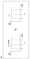
図2は、本実施の形態における増幅回路10のバイパス時における通過特性(周波数特性)の概要を示す図である。図2の(a)は第1切替回路12の通過特性の概要を示し、図2の(b)は増幅回路10全体としてのバイパス時の通過特性を示す。図2の(a)及び(b)では、第1切替回路12の3つの入力端子12a〜12cに入力された信号a〜cの周波数fa、fb及びfcにおける利得(dB)が示されている。
FIG. 2 is a diagram showing an outline of a pass characteristic (frequency characteristic) when the
図2に示される通過特性は、従来のバイパス経路付き増幅回路の通過特性に比べ、広い周波数にわたって利得の差(つまり、通過損失の差)が小さい。このことの理解を容易にするために、参考として、従来のバイパス経路付き増幅回路とその通過特性を示す。 The pass characteristic shown in FIG. 2 has a smaller gain difference (that is, a pass loss difference) over a wider frequency range than the pass characteristic of the conventional amplifier circuit with a bypass path. In order to facilitate understanding of this, as a reference, a conventional amplifying circuit with a bypass path and its passing characteristic are shown.
図3は、一般的な従来のバイパス経路付き増幅回路50の回路図である。増幅回路50は、第1切替回路52、整合回路54、増幅器56及びバイパススイッチ58を備える。
FIG. 3 is a circuit diagram of a typical
第1切替回路52は、信号が入力されている複数の入力端子の一つを選択する。
The
バイパススイッチ58は、入力信号が小電力の信号である(つまり、入力信号を増幅する)場合には、オフになる。これによって、第1切替回路52で選択された信号は、整合回路54を通過して増幅器56に入力され、増幅器56で増幅された後に出力される。一方、入力信号が大電力の信号である(つまり、入力信号を増幅しないでバイパス経路19を通過させる)場合には、バイパススイッチ58は、オンになる。これによって、第1切替回路52で選択された信号は、整合回路54を通過した後にバイパススイッチ58を経て出力される。
The
このように、従来のバイパス経路付き増幅回路50では、バイパス時には、入力信号は、整合回路54を通過した後にバイパススイッチ58を経て出力される。よって、従来のバイパス経路付き増幅回路50では、バイパス時の通過特性は、整合回路54の通過特性とバイパススイッチ58の通過特性の両方の影響を受ける。
Thus, in the
図4は、図3に示された従来のバイパス経路付き増幅回路50のバイパス時における通過特性(周波数特性)の概要を示す図である。図4の(a)は、整合回路54の通過特性の概要を示し、図4の(b)はバイパススイッチ58の通過特性の概要を示し、図4の(c)は増幅回路50全体としてのバイパス時の通過特性の概要を示す。ここでは、増幅回路50全体としてのバイパス時の通過特性(図4の(c))が整合回路54の通過特性(図4の(a))とバイパススイッチ58の通過特性(図4の(b))とを合成したものに相当することが示されている。横軸の周波数は、図2と同様である。
FIG. 4 is a diagram showing an outline of a pass characteristic (frequency characteristic) at the time of bypass of the
従来のバイパス経路付き増幅回路50は、バイパス時においては、入力信号が整合回路54を通過するために、図4の(a)に示されるような整合回路54の周波数特性(つまり、狭い通過帯域をもつ周波数特性)の影響を受け、結果として、図4の(c)に示されるような狭い通過帯域をもつ通過特性を有する。
In the
図2及び図4を比較して分かるように、本実施の形態における増幅回路10によれば、従来の増幅回路50に比べ、バイパス時における周波数依存性が抑制される。
As can be seen from a comparison of FIGS. 2 and 4, according to the
なお、本実施の形態の増幅回路10では、各回路ブロックを別のICパッケージで構成してもよいし、共通のICパッケージで構成してもよい。
Note that in the
例えば、第1切替回路12、整合回路14、増幅器16及び第2切替回路18は、それぞれ、別のICパッケージで構成してもよい。つまり、第1切替回路12、整合回路14、増幅器16及び第2切替回路18は、それぞれ、別の半導体基板上に形成してもよい。このとき、例えば、第1切替回路12及び第2切替回路18を、それぞれ、SOI(Silicon On Insulator)プロセスで製作し、増幅器16をSi−Geプロセスで製作する。
For example, each of the
図5に示されるように、第1切替回路12及び第2切替回路18を一つのICパッケージ20で構成してもよい。つまり、第1切替回路12及び第2切替回路18を一つの半導体基板上に形成してもよい。このとき、例えば、ICパッケージ20をSOIプロセスで製作する。これにより、増幅回路10を構成する部品の実装面積が削減され、かつ、低コスト化がはかられる。
As shown in FIG. 5, the
図6に示されるように、第1切替回路12及び第2切替回路18に加えて、増幅器16も、一つのICパッケージ22で構成してもよい。つまり、第1切替回路12、第2切替回路18及び増幅器16を一つ半導体基板上に形成してもよい。このとき、例えば、ICパッケージ22をSOIプロセスで製作する。これにより、さらに、増幅回路10を構成する部品の実装面積が削減され、かつ、低コスト化がはかられる。
As shown in FIG. 6, in addition to the
(実施の形態2)
次に、本発明の実施の形態2における増幅回路を説明する。
(Embodiment 2)
Next, an amplifier circuit according to Embodiment 2 of the present invention will be described.
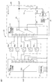
図7は、本発明の実施の形態2における増幅回路30の回路図である。増幅回路30は、アンテナで受信される複数の周波数帯域の信号から一つを選択して増幅する高周波モジュールであり、実施の形態1における増幅回路10に加えて、第3切替回路32、制御回路34及びフィルタ36a〜36eを備える。
FIG. 7 is a circuit diagram of the
第3切替回路32は、入力端子32a及び複数の出力端子32b〜32hを有し、制御回路34から入力される制御信号に従って、入力端子32aを複数の出力端子32b〜32hのいずれかに選択的に接続する回路であり、例えば、SPnT(Single Pole n Throw;nは出力端子(ここでは、周波数帯域)の数)の高周波スイッチで構成される分波器等である。
The
フィルタ36a〜36eのそれぞれは、第3切替回路32の出力端子32b〜32fに1対1対応で接続されたフィルタ回路であり、例えば、対応する周波数帯域の信号だけを通過させるバンドパスフィルタ、ローパスフィルタ、ハイパスフィルタ等である。フィルタ36a〜36eの出力端子は、第1切替回路12の入力端子12a〜12eと1対1対応で接続されている。出力端子32gおよび出力端子32hと、入力端子12fおよび入力端子12gとの間に、所望によりフィルタを接続してもよい。出力端子32gおよび出力端子32hと、入力端子12fおよび入力端子12gとは直接配線で電気的に接続されていてもよい。出力端子32g、出力端子32h、入力端子12fおよび入力端子12gは未接続(端子としてオープン)でもよい。出力端子32g、出力端子32h、入力端子12fおよび入力端子12gに、終端用インピーダンス素子(例えば、50Ωの抵抗)が接続されていてもよい。
Each of the
制御回路34は、第1切替回路12、第3切替回路32及び第2切替回路18に制御信号を出力することで、処理対象の周波数帯域に応じて第1切替回路12及び第3切替回路32を連動して切り替えたり、入力信号の電力の大きさ(つまり、増幅するか否か)に応じて第2切替回路18をオン又はオフさせたりする。
The
なお、この増幅回路30では、第1切替回路12、第3切替回路32、第2切替回路18及び制御回路34は、一つのICパッケージ24で構成されている。つまり、第1切替回路12、第3切替回路32、第2切替回路18及び制御回路34は、一つ半導体基板上に形成されている。ICパッケージ24は、例えば、SOIプロセスで製作され、主要な端子として、第3切替回路32の入力端子32aに接続されたANT端子、第1切替回路12の第1出力端子12iと接続されたAM端子、増幅器16に電源を供給するPON端子、第2切替回路18の入力端子に接続されたAO端子、第1切替回路12の第2出力端子12h及び第2切替回路18の出力端子に接続されたOUT端子等を有する。
In the
以上のように構成された本実施の形態における増幅回路30は、次のように動作する。
The
制御回路34は、処理対象の入力信号が7つの周波数帯域のうちの第1周波数帯域(フィルタ36aに対応する周波数帯域)の信号であり、かつ、その入力信号が小電力の信号である(つまり、入力信号を増幅する)と判断した場合には、第3切替回路32に対して入力端子32aを出力端子32bに接続させるように制御し、第1切替回路12に対して第1出力端子12iを入力端子12aに接続するとともに第2出力端子12hを開放状態にさせ、第2切替回路18をオンさせる。これによって、ANT端子に入力された小電力の入力信号は、第3切替回路32の入力端子32aから出力端子32bを経てフィルタ36aを通過した後に第1切替回路12の入力端子12aに入力され、第1切替回路12の第1出力端子12iからAM端子を経て整合回路14を通過して増幅器16に入力され、増幅器16で増幅された後にAO端子を経て第2切替回路18を通過し、OUT端子より出力される。
In the
一方、制御回路34は、処理対象の入力信号が7つの周波数帯域のうちの第1周波数帯域(フィルタ36aに対応する周波数帯域)の信号であり、かつ、その入力信号が大電力の信号である(つまり、入力信号を増幅しないでバイパス経路19を通過させる)と判断した場合には、第3切替回路32に対して入力端子32aを出力端子32bに接続させるように制御し、第1切替回路12に対して第1出力端子12iを開放状態にするとともに第2出力端子12hを入力端子12aに接続し、第2切替回路18をオフさせる。これによって、ANT端子に入力された大電力の入力信号は、第3切替回路32の入力端子32aから出力端子32bを通過し、第1切替回路12の入力端子12aから第2出力端子12hを通過した後に、整合回路14及び増幅器16とは切り離されたバイパス経路19を経てOUT端子より出力される。
On the other hand, in the
なお、処理対象の入力信号が7つの周波数帯域のうちの他の周波数帯域(例えば、フィルタ36bに対応する周波数帯域)の信号である場合には、制御回路34は、第3切替回路32に対して入力端子32aを対応する出力端子(例えば、出力端子32c)に接続させ、第1切替回路12に対して、入力信号の電力の大小に応じて第1出力端子12i及び第2出力端子12hの一方を対応する入力端子(例えば、入力端子12b)に接続するとともに第1出力端子12i及び第2出力端子12hの他方を開放状態にさせる。これによって、ANT端子に入力された信号は、第3切替回路32を通過した後に対応するフィルタ(例えば、フィルタ36b)を通過した後に第1切替回路12に入力され、入力信号の電力の大小に応じて、増幅器16で増幅されて出力される、又は、バイパス経路19を経て出力される。
If the input signal to be processed is a signal in another frequency band (for example, a frequency band corresponding to the
このように、本実施の形態における増幅回路30は、後段の回路として、実施の形態1と同様の増幅回路10を備える。よって、実施の形態1と同様の効果が奏される。
As described above, the
さらに、本実施の形態における増幅回路30は、実施の形態1の増幅回路10に加えて、前段の回路として、増幅回路10の第1切替回路12に連動して信号を切り替える第3切替回路32、第3切替回路32と第1切替回路12との間に設けられたフィルタ36a〜36e、並びに、第1切替回路12、第3切替回路32及び第2切替回路18を制御する制御回路34を備える。これにより、ANT端子に入力された信号をフィルタ36a〜36eのうちの所望のフィルタに通過させ、必要な周波数帯域の信号だけを取り出して増幅器16で増幅又はバイパス経路19を通過させることが選択的に行われる。
Furthermore, in addition to the
なお、本実施の形態では、第1切替回路12、第3切替回路32、第2切替回路18及び制御回路34は、一つのICパッケージ24で構成されていたが、2以上のICパッケージで構成されてもよい。例えば、第1切替回路12及び第2切替回路18が一つのICパッケージで構成(一つの半導体基板上に形成)され、第3切替回路32及び制御回路34が別のICパッケージで構成(別の半導体基板上に形成)されてもよい。これにより、それぞれの半導体基板において最適な設計を行うことができ、設計の自由度が上がる。
In the present embodiment, the
さらに、増幅器16についても、第1切替回路12、第3切替回路32、第2切替回路18及び制御回路34が形成された半導体基板上に形成(同一のICパッケージで構成)してもよいし、第1切替回路12及び第2切替回路18だけが形成された半導体基板上に形成(同一のICパッケージで構成)してもよい。このとき、例えば、増幅器16を含むICパッケージをSOIプロセスで製作する。これにより、増幅回路30を構成する部品の実装面積が削減され、かつ、低コスト化がはかられる。
Further, the
以上、本発明の増幅回路について、実施の形態1及び2に基づいて説明したが、本発明は、これらの実施の形態に限定されるものではない。本発明の主旨を逸脱しない限り、当業者が思いつく各種変形を実施の形態に施したものや、実施の形態における一部の構成要素を組み合わせて構築される別の形態も、本発明の範囲に含まれる。
While the amplifier circuit of the present invention has been described based on
例えば、第1切替回路12及び第3切替回路32は、一例として高周波スイッチで構成されたが、ダイプレクサ(又は、デュプレクサ)及びトリプレクサ等のフィルタを含む高周波切替回路で構成されてもよい。
For example, although the
図8は、ダイプレクサ又はトリプレクサを用いて第1切替回路12を構成した例を示す図である。図8の(a)は、ダイプレクサ42とデバイダ40とから構成される2入力2出力の切替回路を示す。なお、デバイダ40の2つの出力端子のそれぞれに高周波スイッチ(図示せず)が接続されてもよい。この構成によれば、ダイプレクサ42により、2つの入力端子のそれぞれに入力される異なる周波数帯域の入力信号のいずれかが選択的に出力され、デバイダ40を介してバイパス用信号経路または整合回路に出力される。
FIG. 8 is a diagram illustrating an example in which the
図8の(b)は、トリプレクサ44とデバイダ40とから構成される3入力2出力の切替回路を示す。なお、デバイダ40の2つの出力端子のそれぞれに高周波スイッチ(図示せず)が接続されてもよい。この構成によれば、トリプレクサ44により、3つの入力端子のそれぞれに入力される異なる周波数帯域の入力信号のいずれかが選択的に出力され、デバイダ40を介してバイパス用信号経路または整合回路に出力される。
FIG. 8B shows a three-input two-output switching circuit composed of a
図8の(c)は、2つのダイプレクサ46a及び46bから構成されるトリプレクサ46とデバイダ40とから構成される3入力2出力の切替回路を示す。なお、デバイダ40の2つの出力端子のそれぞれに高周波スイッチ(図示せず)が接続されてもよい。この構成によれば、トリプレクサ46により、3つの入力端子のそれぞれに入力される異なる周波数帯域の入力信号のいずれかが選択的に出力され、デバイダ40を介してバイパス用信号経路または整合回路に出力される。
FIG. 8C shows a three-input two-output switching circuit composed of a
第3切替回路32についても、同様に、ダイプレクサ、トリプレクサ又はこれらの組み合わせによるフィルタで構成することもできる。これにより、第1切替回路12及び第3切替回路32は、ダイプレクサ又はトリプレクサ等のフィルタで構成され、外部からの制御信号を必要とすることなく、入力された信号の周波数帯域に応じて切替(入力信号の選択)が行われる。
Similarly, the
また、実施の形態1及び2では、バイパス経路19は、信号経路だけで構成されたが、これに限られず、信号経路上に減衰器(アッテネータ)が設けられてもよい。図9は、図5に示された増幅回路10のバイパス経路19上に減衰器17を設けて構成される変形例に係る増幅回路10aの回路図である。減衰器17は、信号を減衰させるものであり、例えば、外部からの制御信号に従って減衰量が可変な可変減衰器である。このような減衰器17を備える増幅回路10aによれば、入力信号をバイパス経路19を通過させた場合における挿入損失のレベルを変更することができる。
In the first and second embodiments, the
また、実施の形態2では、制御回路34は、第3切替回路32とともに同じICパッケージで構成されたが、第3切替回路32とは別のICパッケージで構成されてもよい。これにより、制御回路34について、他の回路と独立した最適な設計を行うことができ、設計の自由度が上がる。
In the second embodiment, the
本発明は、バイパス経路付き増幅器として、例えば、アンテナで受信された複数の周波数帯域の信号のいずれかを選択的に増幅又は通過させる高周波モジュールとして利用できる。 The present invention can be used as an amplifier with a bypass path, for example, as a high-frequency module that selectively amplifies or passes any of a plurality of frequency band signals received by an antenna.
10、10a、30 増幅回路
12 第1切替回路
12a〜12g 入力端子
12h 第2出力端子
12i 第1出力端子
14 整合回路
16 増幅器
17 減衰器
18 第2切替回路
19 バイパス経路
20、22、24 ICパッケージ
32 第3切替回路
32a 入力端子
32b〜32h 出力端子
34 制御回路
36a〜36e フィルタ
40 デバイダ
42、46a、46b ダイプレクサ
44、46 トリプレクサ
10, 10a, 30
Claims (9)
前記第1出力端子に接続された整合回路と、
前記整合回路の出力側に接続された増幅器と、
前記増幅器の出力側に接続され、前記第1切替回路が前記第1出力端子を開放状態にするとともに前記第2出力端子を前記複数の入力端子のいずれかに選択的に接続した場合に非導通状態になる第2切替回路と、
前記第2出力端子と前記第2切替回路の出力端子とを電気的に接続するバイパス経路と
を備える増幅回路。 A plurality of input terminals corresponding to a plurality of frequency bands, a first output terminal, and a second output terminal, wherein the first output terminal is selectively connected to any of the plurality of input terminals; The second output terminal is set to the open state with respect to any of the plurality of input terminals, or the second output terminal is set to the open state with respect to any of the plurality of input terminals. A first switching circuit that is selectively connected to any of the plurality of input terminals;
A matching circuit connected to the first output terminal;
An amplifier connected to the output side of the matching circuit;
Non-conductive when connected to the output side of the amplifier and the first switching circuit opens the first output terminal and selectively connects the second output terminal to any of the plurality of input terminals A second switching circuit that enters a state;
An amplifying circuit comprising: a bypass path that electrically connects the second output terminal and the output terminal of the second switching circuit.
請求項1記載の増幅回路。 The amplifier circuit according to claim 1, wherein the first switching circuit and the second switching circuit are formed on a single semiconductor substrate.
前記第3切替回路が有する前記複数の出力端子に1対1対応で接続された複数のフィルタとをさらに備え、
前記第1切替回路が有する前記複数の入力端子は、前記複数のフィルタの出力端子に1対1対応で接続されている
請求項1記載の増幅回路。 A third switching circuit having an input terminal and a plurality of output terminals, and selectively connecting the input terminal to any of the plurality of output terminals;
Further example Bei a plurality of filters connected in one-to-one correspondence to said plurality of output terminals of the third switch circuit,
Before SL said plurality of input terminals of the first switching circuit includes an amplifier circuit according to claim 1, characterized in that connected in one-to-one correspondence to the output terminals of the plurality of filters.
請求項3記載の増幅回路。 The amplifier circuit according to claim 3, wherein the first switching circuit and the second switching circuit are formed on a single semiconductor substrate.
請求項4記載の増幅回路。 The amplifier circuit according to claim 4, wherein the third switching circuit is further formed on the one semiconductor substrate.
請求項4記載の増幅回路。 The amplifier circuit according to claim 4, wherein the third switching circuit is formed on a semiconductor substrate different from the one semiconductor substrate.
請求項2、4〜6のいずれか1項に記載の増幅回路。 The amplifier circuit according to claim 2, wherein the amplifier is formed on the one semiconductor substrate on which the first switching circuit and the second switching circuit are formed.
前記制御回路は、
前記第1切替回路が有する前記複数の入力端子の一つに入力された信号を増幅する場合には、前記第1切替回路において、前記第1出力端子を前記信号が入力されている前記複数の入力端子の一つに接続するとともに、前記第2出力端子を開放状態にするように、前記第1切替回路を制御し、かつ、前記第2切替回路を導通状態に制御し、
前記第1切替回路が有する前記複数の入力端子の一つに入力された信号を増幅しない場合には、前記第1切替回路において、前記第1出力端子を開放状態にするとともに、前記第2出力端子を前記複数の入力端子の一つに接続するように、前記第1切替回路を制御し、かつ、前記第2切替回路を非導通状態に制御する
請求項1〜7のいずれか1項に記載の増幅回路。 A control circuit for controlling the first switching circuit and the second switching circuit;
The control circuit includes:
Wherein when amplifying an input signal to one of said plurality of input terminals first switching circuit has, in the first switching circuit, said plurality of said signal the first output terminal is input Connecting to one of the input terminals, controlling the first switching circuit to open the second output terminal, and controlling the second switching circuit to a conductive state;
When the signal input to one of the plurality of input terminals of the first switching circuit is not amplified, the first output terminal is opened in the first switching circuit, and the second output 8. The first switching circuit is controlled so that a terminal is connected to one of the plurality of input terminals, and the second switching circuit is controlled to be in a non-conduction state. The amplifying circuit described.
請求項1〜8のいずれか1項に記載の増幅回路。 Said first switching circuit, according to signals input prior Symbol plurality of input terminals to any one of claims 1-8 having a diplexer or triplexer selectively outputs in accordance with the frequency band of the signal Amplification circuit.
Priority Applications (4)
| Application Number | Priority Date | Filing Date | Title |
|---|---|---|---|
| KR1020160065457A KR101793109B1 (en) | 2015-07-02 | 2016-05-27 | Amplification circuit |
| US15/192,073 US9722548B2 (en) | 2015-07-02 | 2016-06-24 | Amplification circuit |
| CN201610514654.5A CN106330121A (en) | 2015-07-02 | 2016-07-01 | Amplification circuit |
| US15/631,035 US10181829B2 (en) | 2015-07-02 | 2017-06-23 | Amplification circuit |
Applications Claiming Priority (2)
| Application Number | Priority Date | Filing Date | Title |
|---|---|---|---|
| JP2015133914 | 2015-07-02 | ||
| JP2015133914 | 2015-07-02 |
Publications (2)
| Publication Number | Publication Date |
|---|---|
| JP2017017675A JP2017017675A (en) | 2017-01-19 |
| JP6597461B2 true JP6597461B2 (en) | 2019-10-30 |
Family
ID=57831185
Family Applications (1)
| Application Number | Title | Priority Date | Filing Date |
|---|---|---|---|
| JP2016079139A Active JP6597461B2 (en) | 2015-07-02 | 2016-04-11 | Amplifier circuit |
Country Status (3)
| Country | Link |
|---|---|
| US (1) | US9722548B2 (en) |
| JP (1) | JP6597461B2 (en) |
| KR (1) | KR101793109B1 (en) |
Families Citing this family (8)
| Publication number | Priority date | Publication date | Assignee | Title |
|---|---|---|---|---|
| JP6721472B2 (en) * | 2016-09-20 | 2020-07-15 | 株式会社東芝 | Receiver circuit, wireless communication module, wireless communication device |
| US20180097485A1 (en) * | 2016-10-03 | 2018-04-05 | United States Of America As Represented By Secretary Of The Navy | HPA Bypass Switch |
| WO2018110393A1 (en) * | 2016-12-14 | 2018-06-21 | 株式会社村田製作所 | Switch ic, front-end module, and communication device |
| WO2018142940A1 (en) * | 2017-01-31 | 2018-08-09 | 株式会社村田製作所 | High frequency switch |
| CN110392926B (en) * | 2017-03-14 | 2022-12-06 | 株式会社村田制作所 | High frequency module |
| JP2018181943A (en) | 2017-04-05 | 2018-11-15 | 株式会社村田製作所 | Power amplifier module |
| JP2019220827A (en) | 2018-06-19 | 2019-12-26 | 株式会社村田製作所 | Multiplexer |
| CN115128664B (en) * | 2022-09-01 | 2022-11-08 | 中国科学院地质与地球物理研究所 | Seismic acquisition system based on frequency domain broadening MEMS sensor |
Family Cites Families (13)
| Publication number | Priority date | Publication date | Assignee | Title |
|---|---|---|---|---|
| JP3898714B2 (en) | 2004-07-12 | 2007-03-28 | 株式会社東芝 | Wireless device |
| JP4838536B2 (en) * | 2005-05-20 | 2011-12-14 | 株式会社エヌ・ティ・ティ・ドコモ | Matching circuit |
| FR2902250A1 (en) * | 2006-06-12 | 2007-12-14 | Thomson Licensing Sas | SWITCH AND SELECTIVE ISOLATION SWITCHING DEVICE FOR MULTIMEDIA TERMINALS |
| KR101083920B1 (en) * | 2006-08-11 | 2011-11-15 | 엘지에릭슨 주식회사 | Multi-path doherty amplifier and control method thereof |
| JP2009010826A (en) * | 2007-06-29 | 2009-01-15 | Sony Corp | Multi-band low-noise amplifier and wireless communication apparatus |
| US8301186B2 (en) | 2008-04-04 | 2012-10-30 | Stmicroelectronics Ltd. | Enhanced sensitivity radio frequency front end circuit |
| KR101611381B1 (en) | 2008-10-16 | 2016-04-11 | 삼성전자주식회사 | Apparatus and method for an integrated multi-mode multi-band power amplifier |
| WO2011066861A1 (en) * | 2009-12-03 | 2011-06-09 | Epcos Ag | Power amplifier circuit and front end circuit |
| US20110250926A1 (en) * | 2009-12-21 | 2011-10-13 | Qualcomm Incorporated | Dynamic antenna selection in a wireless device |
| JP2011151771A (en) * | 2009-12-22 | 2011-08-04 | Sumitomo Electric Device Innovations Inc | Electronic circuit |
| KR101305597B1 (en) | 2011-08-08 | 2013-09-09 | 엘지이노텍 주식회사 | Impedance matching apparatus and method |
| US20130043946A1 (en) | 2011-08-16 | 2013-02-21 | Qualcomm Incorporated | Low noise amplifiers with combined outputs |
| JP2014027501A (en) | 2012-07-27 | 2014-02-06 | Sharp Corp | Variable gain amplifier and radio communication apparatus having variable gain amplifier |
-
2016
- 2016-04-11 JP JP2016079139A patent/JP6597461B2/en active Active
- 2016-05-27 KR KR1020160065457A patent/KR101793109B1/en active IP Right Grant
- 2016-06-24 US US15/192,073 patent/US9722548B2/en active Active
Also Published As
| Publication number | Publication date |
|---|---|
| US20170026010A1 (en) | 2017-01-26 |
| JP2017017675A (en) | 2017-01-19 |
| US9722548B2 (en) | 2017-08-01 |
| KR101793109B1 (en) | 2017-11-02 |
| KR20170004846A (en) | 2017-01-11 |
Similar Documents
| Publication | Publication Date | Title |
|---|---|---|
| JP6597461B2 (en) | Amplifier circuit | |
| US10181829B2 (en) | Amplification circuit | |
| CN107689778B (en) | High-frequency module and communication device | |
| US11088720B2 (en) | High-frequency module | |
| WO2017073509A1 (en) | Switch module | |
| JP6965581B2 (en) | High frequency module and communication equipment | |
| US10476531B2 (en) | High-frequency front-end circuit | |
| US10340971B2 (en) | Power amplification module, front-end circuit, and communication device | |
| WO2018116961A1 (en) | High frequency switch and communication device | |
| WO2015001828A1 (en) | Front-end circuit | |
| JP2017208656A (en) | Switch module and high frequency module | |
| WO2020129882A1 (en) | Front end module and communication device | |
| WO2020162072A1 (en) | High frequency module and communication device | |
| US11437959B2 (en) | High frequency amplification circuit, high frequency front-end circuit, and communication device | |
| KR102323572B1 (en) | Multi-band radio-frequency transmitter with receiving band variable filtering function | |
| JP6365795B2 (en) | High frequency module | |
| JP5360163B2 (en) | High frequency front end module | |
| JP5206585B2 (en) | High frequency module | |
| CN106330121A (en) | Amplification circuit | |
| US9467197B2 (en) | Front end circuit | |
| WO2020116056A1 (en) | High frequency module and communication device | |
| JP2019161309A (en) | Multiplexer and communication device |
Legal Events
| Date | Code | Title | Description |
|---|---|---|---|
| A621 | Written request for application examination |
Free format text: JAPANESE INTERMEDIATE CODE: A621 Effective date: 20171013 |
|
| A977 | Report on retrieval |
Free format text: JAPANESE INTERMEDIATE CODE: A971007 Effective date: 20180815 |
|
| A131 | Notification of reasons for refusal |
Free format text: JAPANESE INTERMEDIATE CODE: A131 Effective date: 20180821 |
|
| A601 | Written request for extension of time |
Free format text: JAPANESE INTERMEDIATE CODE: A601 Effective date: 20181019 |
|
| A521 | Written amendment |
Free format text: JAPANESE INTERMEDIATE CODE: A523 Effective date: 20181204 |
|
| A131 | Notification of reasons for refusal |
Free format text: JAPANESE INTERMEDIATE CODE: A131 Effective date: 20190514 |
|
| TRDD | Decision of grant or rejection written | ||
| A01 | Written decision to grant a patent or to grant a registration (utility model) |
Free format text: JAPANESE INTERMEDIATE CODE: A01 Effective date: 20190903 |
|
| A61 | First payment of annual fees (during grant procedure) |
Free format text: JAPANESE INTERMEDIATE CODE: A61 Effective date: 20190916 |
|
| R150 | Certificate of patent or registration of utility model |
Ref document number: 6597461 Country of ref document: JP Free format text: JAPANESE INTERMEDIATE CODE: R150 |