JP6597441B2 - Motor control device - Google Patents
Motor control device Download PDFInfo
- Publication number
- JP6597441B2 JP6597441B2 JP2016061358A JP2016061358A JP6597441B2 JP 6597441 B2 JP6597441 B2 JP 6597441B2 JP 2016061358 A JP2016061358 A JP 2016061358A JP 2016061358 A JP2016061358 A JP 2016061358A JP 6597441 B2 JP6597441 B2 JP 6597441B2
- Authority
- JP
- Japan
- Prior art keywords
- cooling oil
- coil
- motor
- rotation operation
- operation region
- Prior art date
- Legal status (The legal status is an assumption and is not a legal conclusion. Google has not performed a legal analysis and makes no representation as to the accuracy of the status listed.)
- Active
Links
Images


Classifications
-
- H—ELECTRICITY
- H02—GENERATION; CONVERSION OR DISTRIBUTION OF ELECTRIC POWER
- H02P—CONTROL OR REGULATION OF ELECTRIC MOTORS, ELECTRIC GENERATORS OR DYNAMO-ELECTRIC CONVERTERS; CONTROLLING TRANSFORMERS, REACTORS OR CHOKE COILS
- H02P29/00—Arrangements for regulating or controlling electric motors, appropriate for both AC and DC motors
- H02P29/60—Controlling or determining the temperature of the motor or of the drive
- H02P29/64—Controlling or determining the temperature of the winding
-
- B—PERFORMING OPERATIONS; TRANSPORTING
- B60—VEHICLES IN GENERAL
- B60K—ARRANGEMENT OR MOUNTING OF PROPULSION UNITS OR OF TRANSMISSIONS IN VEHICLES; ARRANGEMENT OR MOUNTING OF PLURAL DIVERSE PRIME-MOVERS IN VEHICLES; AUXILIARY DRIVES FOR VEHICLES; INSTRUMENTATION OR DASHBOARDS FOR VEHICLES; ARRANGEMENTS IN CONNECTION WITH COOLING, AIR INTAKE, GAS EXHAUST OR FUEL SUPPLY OF PROPULSION UNITS IN VEHICLES
- B60K6/00—Arrangement or mounting of plural diverse prime-movers for mutual or common propulsion, e.g. hybrid propulsion systems comprising electric motors and internal combustion engines ; Control systems therefor, i.e. systems controlling two or more prime movers, or controlling one of these prime movers and any of the transmission, drive or drive units Informative references: mechanical gearings with secondary electric drive F16H3/72; arrangements for handling mechanical energy structurally associated with the dynamo-electric machine H02K7/00; machines comprising structurally interrelated motor and generator parts H02K51/00; dynamo-electric machines not otherwise provided for in H02K see H02K99/00
- B60K6/20—Arrangement or mounting of plural diverse prime-movers for mutual or common propulsion, e.g. hybrid propulsion systems comprising electric motors and internal combustion engines ; Control systems therefor, i.e. systems controlling two or more prime movers, or controlling one of these prime movers and any of the transmission, drive or drive units Informative references: mechanical gearings with secondary electric drive F16H3/72; arrangements for handling mechanical energy structurally associated with the dynamo-electric machine H02K7/00; machines comprising structurally interrelated motor and generator parts H02K51/00; dynamo-electric machines not otherwise provided for in H02K see H02K99/00 the prime-movers consisting of electric motors and internal combustion engines, e.g. HEVs
- B60K6/22—Arrangement or mounting of plural diverse prime-movers for mutual or common propulsion, e.g. hybrid propulsion systems comprising electric motors and internal combustion engines ; Control systems therefor, i.e. systems controlling two or more prime movers, or controlling one of these prime movers and any of the transmission, drive or drive units Informative references: mechanical gearings with secondary electric drive F16H3/72; arrangements for handling mechanical energy structurally associated with the dynamo-electric machine H02K7/00; machines comprising structurally interrelated motor and generator parts H02K51/00; dynamo-electric machines not otherwise provided for in H02K see H02K99/00 the prime-movers consisting of electric motors and internal combustion engines, e.g. HEVs characterised by apparatus, components or means specially adapted for HEVs
- B60K6/26—Arrangement or mounting of plural diverse prime-movers for mutual or common propulsion, e.g. hybrid propulsion systems comprising electric motors and internal combustion engines ; Control systems therefor, i.e. systems controlling two or more prime movers, or controlling one of these prime movers and any of the transmission, drive or drive units Informative references: mechanical gearings with secondary electric drive F16H3/72; arrangements for handling mechanical energy structurally associated with the dynamo-electric machine H02K7/00; machines comprising structurally interrelated motor and generator parts H02K51/00; dynamo-electric machines not otherwise provided for in H02K see H02K99/00 the prime-movers consisting of electric motors and internal combustion engines, e.g. HEVs characterised by apparatus, components or means specially adapted for HEVs characterised by the motors or the generators
-
- H—ELECTRICITY
- H02—GENERATION; CONVERSION OR DISTRIBUTION OF ELECTRIC POWER
- H02K—DYNAMO-ELECTRIC MACHINES
- H02K11/00—Structural association of dynamo-electric machines with electric components or with devices for shielding, monitoring or protection
- H02K11/20—Structural association of dynamo-electric machines with electric components or with devices for shielding, monitoring or protection for measuring, monitoring, testing, protecting or switching
- H02K11/25—Devices for sensing temperature, or actuated thereby
-
- H—ELECTRICITY
- H02—GENERATION; CONVERSION OR DISTRIBUTION OF ELECTRIC POWER
- H02K—DYNAMO-ELECTRIC MACHINES
- H02K9/00—Arrangements for cooling or ventilating
- H02K9/19—Arrangements for cooling or ventilating for machines with closed casing and closed-circuit cooling using a liquid cooling medium, e.g. oil
-
- H—ELECTRICITY
- H02—GENERATION; CONVERSION OR DISTRIBUTION OF ELECTRIC POWER
- H02P—CONTROL OR REGULATION OF ELECTRIC MOTORS, ELECTRIC GENERATORS OR DYNAMO-ELECTRIC CONVERTERS; CONTROLLING TRANSFORMERS, REACTORS OR CHOKE COILS
- H02P23/00—Arrangements or methods for the control of AC motors characterised by a control method other than vector control
- H02P23/0086—Arrangements or methods for the control of AC motors characterised by a control method other than vector control specially adapted for high speeds, e.g. above nominal speed
- H02P23/009—Arrangements or methods for the control of AC motors characterised by a control method other than vector control specially adapted for high speeds, e.g. above nominal speed using field weakening
-
- H—ELECTRICITY
- H02—GENERATION; CONVERSION OR DISTRIBUTION OF ELECTRIC POWER
- H02P—CONTROL OR REGULATION OF ELECTRIC MOTORS, ELECTRIC GENERATORS OR DYNAMO-ELECTRIC CONVERTERS; CONTROLLING TRANSFORMERS, REACTORS OR CHOKE COILS
- H02P23/00—Arrangements or methods for the control of AC motors characterised by a control method other than vector control
- H02P23/14—Estimation or adaptation of motor parameters, e.g. rotor time constant, flux, speed, current or voltage
Description
本発明は、ハウジング内の冷却油で冷却されるモータの制御装置に関する発明である。 The present invention relates to a control device for a motor cooled by cooling oil in a housing.
モータの過熱を防止する技術として、例えば、特許文献1に記載されたものがある。このものは、モータハウジング内の油の温度を検出する油温センサを備え、この油温センサで検出した油温とモータの熱容量と熱抵抗とに基づいて巻線温度を演算し、この巻線温度に基づいてモータ温度を検出する。この検出したモータ温度が所定以上のときにモータのトルクを制限するようにしている。 As a technique for preventing overheating of a motor, for example, there is one described in Patent Document 1. This is equipped with an oil temperature sensor that detects the temperature of oil in the motor housing, and calculates the winding temperature based on the oil temperature detected by the oil temperature sensor, the heat capacity and thermal resistance of the motor, and this winding The motor temperature is detected based on the temperature. The motor torque is limited when the detected motor temperature is equal to or higher than a predetermined value.
ハウジング内の冷却油で冷却されるモータは、運転領域によって過熱し易い部位が異なってくる。つまり、ロータの回転によって冷却油が掻き揚げられるため、モータの回転速度(つまりロータの回転速度)が低い領域では、冷却油が十分に拡散せずコイルが過熱し易くなる。一方、モータの回転速度が高い領域では、冷却油が十分に拡散してコイルは過熱し難くなるが、コイルの発熱量が大きいため、冷却油が過熱し易くなる。 The motor that is cooled by the cooling oil in the housing has different parts that are likely to overheat depending on the operation region. That is, since the cooling oil is lifted by the rotation of the rotor, the cooling oil is not sufficiently diffused and the coil is easily overheated in a region where the rotation speed of the motor (that is, the rotation speed of the rotor) is low. On the other hand, in a region where the rotational speed of the motor is high, the cooling oil is sufficiently diffused and the coil is difficult to overheat. However, since the amount of heat generated by the coil is large, the cooling oil easily overheats.
しかし、上記特許文献1の技術では、上述したようにモータの運転領域によって過熱し易い部位が異なることが全く考慮されておらず、単にモータ温度が所定以上のときにモータの出力トルクを制限するだけであるため、過熱し易い部位を適切に保護することができない可能性がある。 However, the technique of the above-mentioned Patent Document 1 does not take into consideration that the portion that is easily overheated differs depending on the motor operating region as described above, and simply limits the output torque of the motor when the motor temperature is equal to or higher than a predetermined value. Therefore, there is a possibility that a part that is easily overheated cannot be properly protected.
そこで、本発明が解決しようとする課題は、ハウジング内の冷却油で冷却されるモータにおいて過熱し易い部位を適切に保護することができるモータの制御装置を提供することにある。 Accordingly, an object of the present invention is to provide a motor control device that can appropriately protect a portion that is easily overheated in a motor cooled by cooling oil in a housing.
上記課題を解決するために、請求項1に係る発明は、ハウジング(25)内にステータ(28)とロータ(27)とが配置されて構成されたモータ(16)と前記ハウジング内の冷却油(30)で冷却される前記モータの制御装置において、前記冷却油は、前記ハウジング内の密閉空間に封入されており、前記モータの回転停止時に、前記冷却油は、前記ハウジング内において、前記ロータの最下位面よりも上方であり、且つ前記ロータの回転軸よりも下方の高さ位置まで貯溜されており、前記ステータに設けられたコイル(29)の温度を検出するコイル温度検出手段(31)と、前記冷却油の温度を検出する冷却油温度検出手段(32)と、前記コイル温度検出手段で検出した前記コイルの温度がコイル保護用の閾値を越えた場合に前記モータのトルクを制限するコイル保護用トルク制限と、前記冷却油温度検出手段で検出した前記冷却油の温度が冷却油保護用の閾値を越えた場合に前記モータのトルクを制限する冷却油保護用トルク制限とを実行する制御部(24)とを備え、前記制御部は、前記モータが所定以下の低回転で動作する低回転動作領域では、前記コイル保護用トルク制限が優先的に実行され易くし、前記モータが前記低回転動作領域よりも高回転で動作する高回転動作領域では、前記冷却油保護用トルク制限が優先的に実行され易くするようにしたものである。
In order to solve the above-mentioned problems, the invention according to claim 1 is directed to a motor (16) in which a stator (28) and a rotor (27) are arranged in a housing (25), and cooling oil in the housing. (30) In the motor control apparatus cooled in (30), the cooling oil is enclosed in a sealed space in the housing, and the rotation of the motor causes the cooling oil to move into the rotor when the motor stops rotating. Coil temperature detecting means (31) for detecting the temperature of the coil (29) provided in the stator, being stored up to a height position above the lowermost surface of the rotor and below the rotating shaft of the rotor. ), A cooling oil temperature detecting means (32) for detecting the temperature of the cooling oil, and the coil temperature detected by the coil temperature detecting means when the coil temperature exceeds a threshold for coil protection. Coil protection torque limit for limiting the torque of the motor, and cooling oil protection for limiting the motor torque when the temperature of the cooling oil detected by the cooling oil temperature detection means exceeds a threshold for cooling oil protection And a control unit (24) that executes torque limitation for the coil, and the control unit preferentially executes the torque limitation for coil protection in a low rotation operation region where the motor operates at a low rotation below a predetermined value. In the high rotation operation region where the motor operates at a higher rotation than the low rotation operation region, the torque limitation for cooling oil protection is easily performed preferentially .
この構成では、コイル温度検出手段で検出したコイルの温度がコイル保護用の閾値を越えた場合にモータのトルクを制限するコイル保護用トルク制限を実行することで、コイルの過熱を防止することができる。また、冷却油温度検出手段で検出した冷却油の温度が冷却油保護用の閾値を越えた場合にモータのトルクを制限する冷却油保護用トルク制限を実行することで、冷却油の過熱を防止することができる。 In this configuration, it is possible to prevent overheating of the coil by executing a coil protection torque limit that limits the torque of the motor when the coil temperature detected by the coil temperature detection means exceeds the coil protection threshold. it can. Also, cooling oil protection torque limit that limits the motor torque when the cooling oil temperature detected by the cooling oil temperature detection means exceeds the cooling oil protection threshold value prevents overheating of the cooling oil. can do.
しかも、低回転動作領域では、コイル保護用トルク制限が優先的に実行され易くするため、コイルが過熱し易い低回転動作領域でコイル保護用トルク制限を優先的に実行してコイルの過熱を確実に防止することができ、コイルを適切に保護することができる。一方、高回転動作領域では、冷却油保護用トルク制限が優先的に実行され易くするため、冷却油が過熱し易い高回転動作領域で冷却油保護用トルク制限を優先的に実行して冷却油の過熱を確実に防止することができ、冷却油を適切に保護することができる。 Moreover, in order to make it easier to preferentially execute the coil protection torque limit in the low rotation operation region, the coil protection torque limitation is preferentially executed in the low rotation operation region where the coil is likely to overheat to ensure overheating of the coil. Therefore, the coil can be appropriately protected. On the other hand, in order to make it easier to preferentially execute the cooling oil protection torque limitation in the high rotation operation region, the cooling oil protection torque limitation is preferentially executed in the high rotation operation region in which the cooling oil is likely to overheat. Overheating can be reliably prevented, and the cooling oil can be appropriately protected.
また、請求項2のように、前記制御部は、前記低回転動作領域で前記コイル保護用の閾値を前記高回転動作領域よりも低い値に設定することで前記コイル保護用トルク制限が優先的に実行され易くすると良い。このようにすれば、低回転動作領域では、コイル温度検出手段で検出したコイルの温度が高回転動作領域よりも低いコイル保護用の閾値を越えたときに、コイル保護用トルク制限を開始することができる。これにより、コイルが過熱し易い低回転動作領域でコイル保護用トルク制限を優先的に実行することができ、コイルを確実に保護することができる。 According to a second aspect of the present invention, the control unit preferentially sets the coil protection torque limit by setting the coil protection threshold value to a value lower than the high rotation operation region in the low rotation operation region. It is better to make it easier to execute. In this way, in the low rotation operation region, when the coil temperature detected by the coil temperature detecting means exceeds the lower coil protection threshold than in the high rotation operation region, the coil protection torque limit is started. Can do. As a result, the coil protection torque limit can be preferentially executed in the low-rotation operation region where the coil is likely to overheat, and the coil can be reliably protected.
この場合、請求項3のように、前記制御部は、前記低回転動作領域で且つ前記モータのトルクが所定値以下の領域では前記コイル保護用の閾値を前記高回転動作領域と同じ値に設定するようにしても良い。このようにすれば、低回転動作領域で且つモータのトルクが所定値以下の領域、つまり低回転動作領域のうちコイルの発熱量が少ない領域での不要なトルク制限を避けることができ、モータの運転状態に応じた適切な過熱防止を行うことができる。 In this case, as in claim 3, the control unit sets the coil protection threshold value to the same value as the high rotation operation region in the low rotation operation region and in a region where the torque of the motor is not more than a predetermined value. You may make it do. In this way, it is possible to avoid unnecessary torque limitation in the low rotation operation region and in the region where the motor torque is below a predetermined value, that is, in the low rotation operation region where the amount of heat generated by the coil is small. Appropriate overheating can be prevented according to the operating state.
また、請求項4のように、前記制御部は、前記高回転動作領域で前記冷却油保護用の閾値を前記低回転動作領域よりも低い値に設定することで前記冷却油保護用トルク制限が優先的に実行され易くすると良い。このようにすれば、高回転動作領域では、冷却油温度検出手段で検出した冷却油の温度が低回転動作領域よりも低い冷却油保護用の閾値を越えたときに、冷却油保護用トルク制限を開始することができる。これにより、冷却油が過熱し易い高回転動作領域で冷却油保護用トルク制限を優先的に実行することができ、冷却油を確実に保護することができる。 According to a fourth aspect of the present invention, the controller limits the cooling oil protection torque limit by setting a threshold value for cooling oil protection in the high rotation operation region to a value lower than that in the low rotation operation region. It should be easy to execute with priority. In this way, in the high rotation operation region, when the temperature of the cooling oil detected by the cooling oil temperature detection means exceeds the cooling oil protection threshold value lower than that in the low rotation operation region, the torque limitation for cooling oil protection is performed. Can start. As a result, the torque limitation for cooling oil protection can be preferentially executed in the high rotation operation region where the cooling oil is likely to overheat, and the cooling oil can be reliably protected.
この場合、請求項5のように、前記制御部は、前記高回転動作領域で且つ前記モータの回転速度が所定値以下の領域では前記冷却油保護用の閾値を前記低回転動作領域と同じ値に設定するようにしても良い。このようにすれば、高回転動作領域で且つモータの回転速度が所定値以下の領域、つまり高回転動作領域のうちコイルの発熱量が少なく冷却油の冷却効果が大きい領域での不要なトルク制限を避けることができ、モータの運転状態に応じた適切な過熱防止を行うことができる。 In this case, as in claim 5, the control unit sets the cooling oil protection threshold to the same value as the low rotation operation region in the high rotation operation region and in a region where the rotation speed of the motor is a predetermined value or less. You may make it set to. In this way, unnecessary torque limitation is performed in the high rotation operation region and in the region where the rotation speed of the motor is equal to or less than the predetermined value, that is, in the high rotation operation region where the amount of heat generated by the coil is small and the cooling oil cooling effect is large. Thus, it is possible to prevent overheating appropriately according to the operating state of the motor.
また、請求項6のように、前記低回転動作領域は、前記モータの弱め界磁制御を実施しない非弱め界磁領域としても良い。つまり、非弱め界磁領域でコイル保護用トルク制限が優先的に実行され易くする。非弱め界磁領域は、弱め界磁領域よりもモータが低回転で動作する領域となる。従って、非弱め界磁領域でコイル保護用トルク制限が優先的に実行され易くすることで、コイルが過熱し易い低回転動作領域でコイル保護用トルク制限を優先的に実行して、コイルを適切に保護することができる。 According to a sixth aspect of the present invention, the low rotation operation region may be a non-weak field region in which field weakening control of the motor is not performed. That is, the coil protection torque limit is easily preferentially executed in the non-weakening field region. The non-weakening field region is a region where the motor operates at a lower speed than the weakening field region. Therefore, by making the coil protection torque limit preferentially executed in the non-weakening field region, the coil protection torque limit is preferentially executed in the low rotation operation region where the coil is likely to overheat, and the coil is appropriately set. Can be protected.
更に、請求項7のように、前記高回転動作領域は、前記モータの弱め界磁制御を実施する弱め界磁領域としても良い。つまり、弱め界磁領域で冷却油保護用トルク制限が優先的に実行され易くする。弱め界磁領域は、非弱め界磁領域よりもモータが高回転で動作する領域となる。従って、弱め界磁領域で冷却油保護用トルク制限が優先的に実行され易くすることで、冷却油が過熱し易い高回転動作領域で冷却油保護用トルク制限を優先的に実行して、冷却油を適切に保護することができる。 Further, as in claim 7, the high rotation operation region may be a field weakening region in which field weakening control of the motor is performed. That is, the torque limitation for cooling oil protection is preferentially executed in the field weakening region. The field weakening region is a region where the motor operates at a higher speed than the non-weakening field region. Therefore, by preferentially executing the cooling oil protection torque limitation in the field weakening region, the cooling oil protection torque limitation is preferentially executed in the high rotation operation region where the cooling oil is likely to be overheated. The oil can be properly protected.
ところで、コイルのうちモータの回転停止時に冷却油に浸漬しない部分は、冷却油に浸漬する部分よりも高温になり易い。更に、コイルの内部は、コイルの外部よりも高温になり易い。また、コイルの中性点は、コイルのうち最も発熱する部分である。また、ロータの回転によって冷却油が掻き揚げられるため、コイルのうち冷却油に浸漬しない範囲ではロータの回転方向の進み側ほど冷却油がかかり難く高温になり易い。 By the way, the portion of the coil that is not immersed in the cooling oil when the motor stops rotating is likely to be hotter than the portion that is immersed in the cooling oil. Furthermore, the inside of the coil tends to be hotter than the outside of the coil. Further, the neutral point of the coil is the most heat generating portion of the coil. In addition, since the cooling oil is lifted by the rotation of the rotor, the cooling oil is less likely to be applied to the advance side in the rotation direction of the rotor in the range where the coil is not immersed in the cooling oil, and the temperature tends to increase.
そこで、請求項8のように、前記コイル温度検出手段は、前記コイルのうち前記モータの回転停止時に前記冷却油に浸漬しない位置に設置されたコイル温度センサであるようにすると良い。更に、請求項9のように、前記コイル温度センサは、前記コイルの内部に設置されているようにしても良い。また、請求項10のように、前記コイル温度センサは、前記コイルの中性点に設置されているようにしても良い。また、請求項11のように、前記コイル温度センサは、前記コイルのうち前記モータの回転停止時に前記冷却油に浸漬しない範囲内で前記ロータの回転方向の進み側に設置されているようにしても良い。請求項8〜11のいずれの場合も、コイルのうち高温になり易い部分の温度をコイル温度センサで検出することができるため、コイル温度センサの検出値に基づいたコイル保護用トルク制限を適切なタイミングで開始して、適切な過熱防止を行うことができる。
Therefore, as described in claim 8, the coil temperature detecting means may be a coil temperature sensor installed in a position where the coil is not immersed in the cooling oil when rotation of the motor is stopped. Further, as in claim 9, the coil temperature sensor may be installed inside the coil. The coil temperature sensor may be installed at a neutral point of the coil. Further, as in
また、請求項12のように、前記冷却油温度検出手段は、前記冷却油に浸漬し且つ前記コイルから離れた位置に設置されているようにすると良い。このようにすれば、冷却油温度検出手段で冷却油の温度を常に検出することができる。 According to a twelfth aspect of the present invention, it is preferable that the cooling oil temperature detecting means is installed at a position immersed in the cooling oil and away from the coil. In this way, the temperature of the cooling oil can always be detected by the cooling oil temperature detecting means.
ロータの回転によって冷却油が掻き揚げられるため、冷却油の油面がロータの最下位面よりも下がることはない。また、冷却油がロータの回転方向の進み側に偏り易い。そこで、請求項13のように、前記冷却油温度検出手段は、前記ロータの最下位面よりも下方に設置されているようにしても良い。また、請求項14のように、前記冷却油温度検出手段は、前記冷却油に浸漬する範囲内で前記ロータの回転方向の進み側に設置されているようにしても良い。このようにすれば、冷却油温度検出手段が常に冷却油に浸漬するようにできる。 Since the cooling oil is lifted by the rotation of the rotor, the oil level of the cooling oil does not fall below the lowest surface of the rotor. In addition, the cooling oil tends to be biased toward the advance side in the rotational direction of the rotor. Therefore, as in a thirteenth aspect of the present invention, the cooling oil temperature detecting means may be installed below the lowest surface of the rotor. According to a fourteenth aspect of the present invention, the cooling oil temperature detecting means may be installed on the advance side in the rotational direction of the rotor within a range immersed in the cooling oil. In this way, the cooling oil temperature detecting means can always be immersed in the cooling oil.
また、請求項1のように、前記冷却油は、前記ハウジング内の密閉空間に封入され、前記ロータの最下位面よりも上方で且つ前記ロータの回転軸よりも下方の高さ位置まで貯溜されているようにすると良い。冷却油をロータの最下位面よりも上方の高さ位置まで貯溜することで、モータの内部の熱を冷却油を介して効率的にハウジングに伝導させてモータの外部に放出することができ、モータを効果的に冷却することができる。しかも、冷却油をロータの回転軸よりも下方の高さ位置まで貯溜することで、封入する冷却油の量を適度に抑えて冷却油によるモータの回転負荷を適度に抑えることができる。
Moreover, as of claim 1, wherein the cooling oil, the is sealed in the closed space in the housing, is the reservoir to a height position below and the axis of rotation of the rotor above the lowermost surface of the rotor It is good to have you. By storing the cooling oil up to a height position above the lowest surface of the rotor, the heat inside the motor can be efficiently conducted to the housing via the cooling oil and released to the outside of the motor, The motor can be effectively cooled. In addition, by storing the cooling oil to a height position below the rotation axis of the rotor, the amount of the cooling oil to be sealed can be moderately suppressed, and the rotational load of the motor due to the cooling oil can be moderately suppressed.
この場合、請求項15のように、前記コイルは、少なくとも一つの中性点が前記冷却油に浸漬するように配置されているようにすると良い。冷却油がハウジング内の密閉空間に封入された油密構成では、冷却油をモータの外部と循環させる構成に比べて冷却性能が低下するが、コイルのうち最も発熱する部分である中性点を冷却油に浸漬することで、コイルを効果的に冷却することができる。
In this case, as in the fifteenth aspect , the coil is preferably arranged such that at least one neutral point is immersed in the cooling oil. In the oil-tight configuration in which the cooling oil is sealed in the sealed space in the housing, the cooling performance is reduced compared to the configuration in which the cooling oil is circulated outside the motor, but the neutral point that is the most heat-generating part of the coil is reduced. The coil can be effectively cooled by being immersed in the cooling oil.
本発明は、請求項16のように、車両の動力源として搭載されているモータに適用すると良い。このようにすれば、モータの動作領域が頻繁に変化する車両用のモータであっても確実にコイル及び冷却油を保護することができる。
The present invention is, as in the
この場合、請求項17のように、前記冷却油温度検出手段は、前記ハウジング内のうち前記車両の前方側に設置されているようにすると良い。このようにすれば、モータの使用頻度の多い減速時(例えば回生発電時)に冷却油が車両の前方側に移動しても、冷却油温度検出手段で冷却油の温度を確実に検出することができる。
In this case, as in a seventeenth aspect of the present invention, the cooling oil temperature detection means may be installed on the front side of the vehicle in the housing. In this way, even when the cooling oil moves to the front side of the vehicle during deceleration of the motor that is frequently used (for example, during regenerative power generation), the temperature of the cooling oil can be reliably detected by the cooling oil temperature detecting means. Can do.
また、請求項18のように、前記冷却油温度検出手段は、冷却油温度センサであると良い。 Also, as in claim 18, wherein the cooling oil temperature detecting means may is cooling oil temperature sensor.
以下、本発明を実施するための形態を具体化した幾つかの実施例を説明する。 Hereinafter, some embodiments embodying the mode for carrying out the present invention will be described.
本発明の実施例1を図1乃至図7に基づいて説明する。
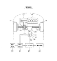
まず、図1に基づいてハイブリッド車の制御システムの概略構成を説明する。
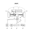
車両の動力源となるエンジン11と、このエンジン11に接続された変速機12とが車両の前側部に搭載されている。変速機12は、機械式の変速機であり、複数の変速段の中から変速段を段階的に切り換える有段変速機であっても良いし、無段階に変速する無段変速機(いわゆるCVT)であっても良い。これらのエンジン11及び変速機12は、エンジン11の出力軸(つまりクランク軸)の軸方向が車両の左右方向となるように横置きで配置されている。エンジン11の出力軸の動力が変速機12に伝達され、この変速機12の出力軸の動力がディファレンシャルギヤ機構13等を介して車輪15の駆動軸14に伝達される。
A first embodiment of the present invention will be described with reference to FIGS.
First, a schematic configuration of a hybrid vehicle control system will be described with reference to FIG.
An
更に、車両の動力源となる小径のモータジェネレータ(以下「MG」と表記する)16と、このMG16に接続された小径の減速機17とがエンジン11及び変速機12の後方に搭載されている。MG16及び減速機17は、出力軸の軸方向が車両の前後方向となるように縦置きで配置されている。ディファレンシャルギヤ機構13のリングギヤ19(つまり変速機12の出力軸の動力が入力されるギヤ)にトランスファ20を介して減速機17の出力軸が連結されている。これにより、MG16の出力軸の動力が減速機17に伝達され、この減速機17の出力軸の動力がトランスファ20やディファレンシャルギヤ機構13等を介して車輪15の駆動軸14に伝達される。
Further, a small-diameter motor generator (hereinafter referred to as “MG”) 16 serving as a power source for the vehicle and a small-
また、MG16を駆動するインバータ21が高圧電池22に接続され、MG16がインバータ21を介して高圧電池22と電力を授受するようになっている。高圧電池22は、二次電池等からなる直流電源である。インバータ21は、高圧電池22の直流電圧を交流電圧に変換してMG16を後述するHV−ECU23からのトルク指令値に従って駆動するとともに、必要に応じて前記トルク指令値を制限して駆動する。
An
HV−ECU23は、車両全体を総合的に制御する制御装置であり、各種のセンサやスイッチ(例えば、アクセルセンサ、シフトスイッチ、ブレーキスイッチ、車速センサ等)の出力信号を読み込んで、車両の運転状態を検出する。このHV−ECU23は、MG−ECU24や図示しないエンジンECU等との間で制御信号やデータ信号を送受信する。MG−ECU24は、インバータ21を制御してMG16を制御する制御装置であり、エンジンECUは、エンジン11の運転を制御する制御装置である。
The HV-
HV−ECU23は、各ECUによって車両の運転状態に応じて、エンジン11、MG16等を制御する。その際、HV−ECU23は、走行モードを、例えば、エンジン走行モードとアシスト走行モードとEV走行モードとの間で切り換える。エンジン走行モードでは、エンジン11とMG16のうちエンジン11の動力のみで車輪15を駆動して車両を走行させるエンジン走行を行う。アシスト走行モードでは、エンジン11の動力とMG16の動力の両方で車輪15を駆動して車両を走行させるアシスト走行を行う。EV走行モードでは、エンジン11とMG16のうちMG16の動力のみで車輪15を駆動して車両を走行させるEV走行を行う。
The HV-
また、HV−ECU23は、車両を制動する際(例えばアクセルオフ時やブレーキオン時に制動力を発生させる際)に、走行モードを回生発電モードに切り換える。この回生発電モードでは、車輪15の動力でMG16を駆動することで、車両の運動エネルギをMG16で電気エネルギに変換する回生発電を行い、その発電電力である回生電力を高圧電池22に充電する。
Further, the HV-
次に、図2に基づいてMG16のトルク制御を説明する。
MG16は、例えば三相永久磁石式同期モータで、永久磁石が内蔵されたものであり、ロータ27の回転位置θ(つまり回転角)を検出する回転位置センサ38が搭載されている。インバータ21は、MG−ECU24から出力される三相の6アーム電圧指令信号UU,UL,VU,VL,WU,WLに基づいて、高圧電池22の直流電圧を三相の交流電圧U,V,Wに変換してMG16を駆動する。MG16のU相に流れるU相電流iu やW相に流れるW相電流iw が電流センサ34によって検出される。
Next, torque control of the
The
MG−ECU24は、MG16の出力トルクが要求トルク(つまりトルク指令値)となるようにインバータ21を制御してMG16に印加する交流電圧を調整するトルク制御を実行する。このトルク制御では、HV−ECU23から出力される要求トルクに基づいた電流指令値と、電流センサ34の出力に基づいた電流検出値との偏差が小さくなるようにMG16の通電をフィードバック制御する電流F/B制御を次のようにして実行する。その際、MG16のロータ回転座標として設定された回転座標系であるd−q座標系において、d軸電流id とq軸電流iq をそれぞれ独立にフィードバック制御する。
The MG-
MG−ECU24は、まず、電流指令変換部35で、MG16の要求トルクと回転速度とに基づいて、指令電流ベクトル(d軸電流指令値Id ,q軸電流指令値Iq )をマップ又は数式等により演算する。
First, the MG-
この後、電流F/B制御部36で、電流センサ34で検出したMG16のU相電流iu とW相電流iw と、回転位置センサ38で検出したMG16のロータ回転位置θとに基づいて、MG16に流れる電流の検出値である検出電流ベクトル(d軸電流検出値id ,q軸電流検出値iq )を演算する。そして、d軸電流指令値Id とd軸電流検出値id との偏差Δid が小さくなるようにPI制御等によりd軸電圧指令値Vd を演算すると共に、q軸電流指令値Iq とq軸電流検出値iq との偏差Δiq が小さくなるようにPI制御等によりq軸電圧指令値Vq を演算して、指令電圧ベクトル(d軸電圧指令値Vd ,q軸電圧指令値Vq )を求める。
Thereafter, the current F /
この後、PWM変換部37で、指令電圧ベクトル(d軸電圧指令値Vd ,q軸電圧指令値Vq )と、MG16のロータ回転位置θとに基づいて、三相変調又は二相変調で三相電圧指令値Vu ,Vv ,Vw を演算し、これらの三相電圧指令値Vu ,Vv ,Vw を、正弦波PWM制御方式で三相の6アーム電圧指令信号UU,UL,VU,VL,WU,WLに変換する。これらの三相の6アーム電圧指令信号UU,UL,VU,VL,WU,WLをインバータ21に出力する。
Thereafter, the
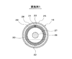
次に、図3及び図4に基づいてMG16の概略構成を説明する。
図3及び図4に示すように、MG16のハウジング25内には、回転軸26と一体的に回転するロータ27と、このロータ27の外周側に配置されたステータ28とが設けられている。ステータ28には、複数の相巻線よりなるコイル29が巻装されている。
Next, a schematic configuration of the
As shown in FIGS. 3 and 4, in the
また、ハウジング25内の密閉空間に、MG16を冷却するための冷却油30が封入されている。この冷却油30は、MG16の回転停止状態でロータ27の最下位面よりも上方で且つロータ27の回転軸26よりも下方の高さ位置まで貯溜されている。MG16が回転したときに、ロータ27の回転によって冷却油30が掻き上げられてハウジング25内に拡散するようになっている。冷却油30は、絶縁性を有する液体であり、例えば自動変速機用の作動油(いわゆるATF)等の自動車用の潤滑油が用いられる。
Further, a cooling
更に、ハウジング25内には、コイル29の温度を検出するコイル温度センサ31と、冷却油30の温度を検出する冷却油温度センサ32が設けられている。コイル温度センサ31は、コイル29のうちMG16の回転停止時に冷却油30に浸漬しない位置に設置されている。更に、コイル温度センサ31は、コイル29の内部(つまり内周側)で且つコイル29の中性点33に位置するように設置されている。冷却油温度センサ32は、冷却油30に浸漬し且つコイル29から離れた位置(つまりコイル29に接触しない位置)に設置されている。更に、冷却油温度センサ32は、ロータ27の最下位面よりも下方に位置するように設置されている。
Furthermore, a
図1に示すように、コイル温度センサ31の出力信号と冷却油温度センサ32の出力信号は、MG−ECU24に入力される。本実施例1では、MG16のコイル29や冷却油30の過熱を防止するために、MG−ECU24により後述する図6及び図7の過熱防止用のルーチンを実行することで、次のような過熱防止制御を行う。コイル温度センサ31で検出したコイル29の温度Tc がコイル保護用の閾値Aを越えた場合にMG16のトルクを制限するコイル保護用トルク制限を実行する。また、冷却油温度センサ32で検出した冷却油30の温度To が冷却油保護用の閾値Cを越えた場合にMG16のトルクを制限する冷却油保護用トルク制限を実行する。
As shown in FIG. 1, the output signal of the
すなわちコイル保護用トルク制限または冷却油保護用トルク制限が実行されると、前述したMG−ECU24がインバータ21を制御して、MG16に印加する交流電圧を減少させる。なお、MG16に印加する交流電圧を減少させると、MG16が出力するトルクが減少する。そこで、MG16から出力されるトルクの減少分を補うように、HV−ECU23がエンジンECUにエンジン出力を増大させるように指示することが望ましい。
That is, when the coil protection torque limit or the cooling oil protection torque limit is executed, the MG-
ところで、ハウジング25内の冷却油30で冷却されるMG16は、運転領域によって過熱し易い部位が異なってくる。つまり、ロータ27の回転によって冷却油30が掻き揚げられるため、MG16の回転速度(つまりロータ27の回転速度)が低い領域では、冷却油30が十分に拡散せずコイル29が過熱し易くなる。一方、MG16の回転速度が高い領域では、冷却油30が十分に拡散してコイル29は過熱し難くなるが、コイル29の発熱量が大きいため、冷却油30が過熱し易くなる。
By the way, the part where MG16 cooled with the cooling
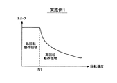
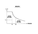
そこで、本実施例1では、図5に示すように、MG16の運転領域を、MG16が所定回転速度N1 以下の低回転で動作する低回転動作領域と、MG16が所定回転速度N1 よりも高回転で動作する高回転動作領域とに区分する。
Therefore, in the first embodiment, as shown in FIG. 5, the operating range of the
そして、低回転動作領域では、コイル保護用トルク制限が冷却油保護用トルク制限よりも優先的に実行され易くする。具体的には、低回転動作領域でコイル保護用の閾値Aを高回転動作領域よりも低い値に設定することでコイル保護用トルク制限が冷却油保護用トルク制限よりも優先的(例えば早め)に実行され易くする。これにより、コイル29が過熱し易い低回転動作領域でコイル保護用トルク制限を優先的に実行してコイル29の過熱を確実に防止できるようにする。すなわちMG16に印加する交流電圧を減少させることで、コイル29の単位時間あたりの発熱量を低下させ、コイル29の過熱を防止する。
In the low-rotation operation region, the coil protection torque limit is more easily executed preferentially than the cooling oil protection torque limit. Specifically, the coil protection torque limit is prioritized (for example, earlier) than the cooling oil protection torque limit by setting the coil protection threshold A to a value lower than the high rotation operation area in the low rotation operation area. To make it easier to implement. This preferentially executes the coil protection torque limit in the low-rotation operation region where the
一方、高回転動作領域では、冷却油保護用トルク制限がコイル保護用トルク制限よりも優先的に実行され易くする。具体的には、高回転動作領域で冷却油保護用の閾値Cを低回転動作領域よりも低い値に設定することで冷却油保護用トルク制限がコイル保護用トルク制限よりも優先的(例えば早め)に実行され易くする。これにより、冷却油30が過熱し易い高回転動作領域で冷却油保護用トルク制限を優先的に実行して冷却油30の過熱を確実に防止できるようにする。すなわちMG16に印加する交流電圧を減少させるため、コイル29の単位時間あたりの発熱量が低下する。そしてコイル29から冷却油30へ伝達する熱量も低下するため、冷却油30の過熱を防止する。
On the other hand, in the high rotation operation region, the torque limitation for cooling oil protection is more preferentially executed than the torque limitation for coil protection. Specifically, by setting the cooling oil protection threshold C to a value lower than that in the low rotation operation region in the high rotation operation region, the cooling oil protection torque limit has priority over the coil protection torque limit (for example, earlier). ) To be executed easily. Thus, the cooling oil protection torque limit is preferentially executed in the high-rotation operation region where the cooling
以下、本実施例1でMG−ECU24が実行する図6及び図7の過熱防止用のルーチンの処理内容を説明する。
図6に示す過熱防止制御ルーチンは、MG−ECU24の電源オン期間中に所定周期で繰り返し実行され、特許請求の範囲でいう制御部としての役割を果たす。また、図7に示す閾値設定ルーチンは、図6のステップ101で実行されるサブルーチンであり、特許請求の範囲でいう制御部としての役割を果たす。
Hereinafter, the processing contents of the overheat prevention routine of FIGS. 6 and 7 executed by the MG-
The overheat prevention control routine shown in FIG. 6 is repeatedly executed at a predetermined cycle during the power-on period of the MG-
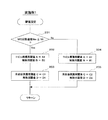
図6の過熱防止制御ルーチンが起動されると、まず、ステップ101で、図7の閾値設定ルーチンを実行する。この閾値設定ルーチンが起動されると、まず、ステップ201で、MG16の回転速度Nm が所定回転速度N1 以下か否かによって低回転動作領域か否かを判定する。
When the overheat prevention control routine of FIG. 6 is started, first, in
このステップ201で、MG16の回転速度Nm が所定回転速度N1 以下と判定された場合には、低回転動作領域と判定する。この場合、ステップ202に進み、コイル保護用閾値AをA2 (例えば180℃)に設定し、このコイル保護用閾値Aよりも低い解除用閾値BをB2 に設定する。
コイル保護用閾値A=A2
解除用閾値B=B2
If it is determined in
Coil protection threshold A = A2
Release threshold B = B2
ここで、A2 はA1 よりも低い値(つまりA2 <A1 )に設定され、B2 はB1 よりも低い値(つまりB2 <B1 )に設定されている。これにより、コイルが発熱し易い低回転動作領域では、コイル保護用閾値Aを高回転動作領域よりも低い値に設定されるため、コイル保護用トルク制限が冷却油保護用トルク制限よりも優先的に実行され易くすることができる。上記「優先的に実行され易くする」とは必ず優先的に実行されることを意味しない。コイルの温度と冷却油の温度は常に同じ関係式で表されるものではなく、環境条件に応じて両者の温度差にはばらつきが生じる。よって、低回転動作領域であっても冷却油保護用トルク制限が実行され、コイル保護用トルク制限が実行されない場合を皆無とはしない。本実施例においてはコイル保護用トルク制限が冷却油保護用トルク制限よりも優先的に実行され易いとは、コイル保護用トルク制限が冷却油保護用トルク制限よりも先に実行される条件が広いことを意味する。以下についても考え方は同様である。 Here, A2 is set to a value lower than A1 (that is, A2 <A1), and B2 is set to a value lower than B1 (that is, B2 <B1). Thus, in the low rotation operation region where the coil is likely to generate heat, the coil protection threshold A is set to a value lower than that in the high rotation operation region, so the coil protection torque limit has priority over the cooling oil protection torque limit. Can be easily implemented. The above-mentioned “make it preferentially executed” does not mean that it is always executed preferentially. The temperature of the coil and the temperature of the cooling oil are not always expressed by the same relational expression, and the temperature difference between the two varies depending on the environmental conditions. Therefore, there is no case where the torque limitation for cooling oil protection is executed and the torque limitation for coil protection is not executed even in the low rotation operation region. In the present embodiment, the fact that the coil protection torque limit is more likely to be executed preferentially than the cooling oil protection torque limit is that the conditions under which the coil protection torque limit is executed before the cooling oil protection torque limit are wide. Means that. The same is true for the following.
この後、ステップ203に進み、冷却油保護用閾値CをC1 (例えば120℃)に設定し、この冷却油保護用閾値Cよりも低い解除用閾値DをD1 に設定する。
冷却油保護用閾値C=C1
解除用閾値D=D1
Thereafter, the process proceeds to step 203, where the cooling oil protection threshold C is set to C1 (for example, 120 ° C.), and the release threshold D lower than the cooling oil protection threshold C is set to D1.
Cooling oil protection threshold C = C1
Release threshold D = D1
ここで、C1 はC2 よりも高い値(つまりC1 >C2 )に設定され、D1 はD2 よりも高い値(つまりD1 >D2 )に設定されている。これにより、低回転動作領域では、冷却油保護用閾値Cを高回転動作領域よりも高い値に設定する。 Here, C1 is set to a value higher than C2 (that is, C1> C2), and D1 is set to a value higher than D2 (that is, D1> D2). Thereby, in the low rotation operation region, the cooling oil protection threshold C is set to a higher value than in the high rotation operation region.
一方、上記ステップ201で、MG16の回転速度Nm が所定回転速度N1 よりも高いと判定された場合には、高回転動作領域と判定する。この場合、ステップ204に進み、コイル保護用閾値AをA1 (例えば200℃)に設定し、このコイル保護用閾値Aよりも低い解除用閾値BをB1 に設定する。
コイル保護用閾値A=A1
解除用閾値B=B1
On the other hand, if it is determined in
Coil protection threshold A = A1
Release threshold B = B1
ここで、A1 はA2 よりも高い値(つまりA1 >A2 )に設定され、B1 はB2 よりも高い値(つまりB1 >B2 )に設定されている。これにより、高回転動作領域では、コイル保護用閾値Aを低回転動作領域よりも高い値に設定する。 Here, A1 is set to a value higher than A2 (that is, A1> A2), and B1 is set to a value higher than B2 (that is, B1> B2). Thus, in the high rotation operation region, the coil protection threshold A is set to a value higher than that in the low rotation operation region.
この後、ステップ205に進み、冷却油保護用閾値CをC2 (例えば100℃)に設定し、この冷却油保護用閾値Cよりも低い解除用閾値DをD2 に設定する。
冷却油保護用閾値C=C2
解除用閾値D=D2
Thereafter, the routine proceeds to step 205, where the cooling oil protection threshold C is set to C2 (for example, 100 ° C.), and the release threshold D lower than the cooling oil protection threshold C is set to D2.
Cooling oil protection threshold C = C2
Release threshold D = D2
ここで、C2 はC1 よりも低い値(つまりC2 <C1 )に設定され、D2 はD1 よりも低い値(つまりD2 <D1 )に設定されている。これにより、冷却油が発熱し易い高回転動作領域では、冷却油保護用閾値Cを低回転動作領域よりも低い値に設定されるため、冷却油保護用トルク制限がコイル保護用トルク制限よりも優先的に実行され易くすることができる。 Here, C2 is set to a value lower than C1 (that is, C2 <C1), and D2 is set to a value lower than D1 (that is, D2 <D1). Thus, in the high rotation operation region where the cooling oil is likely to generate heat, the cooling oil protection threshold C is set to a value lower than that in the low rotation operation region, so that the cooling oil protection torque limit is greater than the coil protection torque limit. It is possible to facilitate execution with priority.
以上のようにして各閾値A〜Dを設定した後、図6のステップ102に進む。このステップ102で、コイル温度センサ31で検出したコイル29の温度Tc がコイル保護用閾値Aよりも高いか否かを判定する。
After setting the thresholds A to D as described above, the process proceeds to step 102 in FIG. In this
このステップ102で、コイル29の温度Tc がコイル保護用閾値Aよりも高いと判定された場合には、ステップ103に進む。このステップ103で、コイル保護用トルク制限を実行して、MG16のトルクを所定の上限ガード値で制限する(例えばMG16のトルクが上限ガード値を越えないようにMG16の通電を制御する)。
If it is determined in
一方、上記ステップ102で、コイル29の温度Tc がコイル保護用閾値A以下と判定された場合には、ステップ104に進む。このステップ104で、コイル温度センサ31で検出したコイル29の温度Tc が解除用閾値Bよりも低いか否かを判定する。
On the other hand, if it is determined in
このステップ104で、コイル29の温度Tc が解除用閾値Bよりも低いと判定された場合には、ステップ105に進み、コイル保護用トルク制限を解除する。
ステップ106では、冷却油温度センサ32で検出した冷却油30の温度To が冷却油保護用閾値Cよりも高いか否かを判定する。
If it is determined in
In
このステップ106で、冷却油30の温度To が冷却油保護用閾値Cよりも高いと判定された場合には、ステップ107に進む。このステップ107で、冷却油保護用トルク制限を実行して、MG16のトルクを所定の上限ガード値で制限する(例えばMG16のトルクが上限ガード値を越えないようにMG16の通電を制御する)。
If it is determined in
一方、上記ステップ106で、冷却油30の温度To が冷却油保護用閾値C以下と判定された場合には、ステップ108に進む。このステップ108で、冷却油温度センサ32で検出した冷却油30の温度To が解除用閾値Dよりも低いか否かを判定する。
このステップ108で、冷却油30の温度To が解除用閾値Dよりも低いと判定された場合には、ステップ109に進み、冷却油保護用トルク制限を解除する。
On the other hand, if it is determined in
If it is determined in
以上説明した本実施例1では、コイル温度センサ31で検出したコイル29の温度Tc がコイル保護用閾値Aを越えた場合にMG16のトルクを制限するコイル保護用トルク制限を実行することで、コイル29の過熱を防止することができる。また、冷却油温度センサ32で検出した冷却油30の温度To が冷却油保護用閾値Cを越えた場合にMG16のトルクを制限する冷却油保護用トルク制限を実行することで、冷却油30の過熱を防止することができる。
In the first embodiment described above, the coil protection torque limit that limits the torque of the
しかも、低回転動作領域では、コイル保護用トルク制限が優先的に実行され易くするようにしている。これにより、コイル29が過熱し易い低回転動作領域でコイル保護用トルク制限を優先的に実行してコイル29の過熱を確実に防止することができ、コイル29を適切に保護することができる。一方、高回転動作領域では、冷却油保護用トルク制限が優先的に実行され易くするようにしている。これにより、冷却油30が過熱し易い高回転動作領域で冷却油保護用トルク制限を優先的に実行して冷却油30の過熱を確実に防止することができ、冷却油30を適切に保護することができる。このため、動作領域が頻繁に変化する車両用のMG16であっても確実にコイル29及び冷却油30を保護することができる。また、冷却油30の過熱防止を行うことで、冷却油30の交換頻度を少なくすることができる、或は、冷却油30の交換を不要にすることができるという利点もある。
In addition, in the low-rotation operation region, the coil protection torque limit is easily executed with priority. As a result, it is possible to preferentially execute the coil protection torque limit in the low-rotation operation region where the
また、本実施例1では、低回転動作領域でコイル保護用閾値Aを高回転動作領域よりも低い値に設定することでコイル保護用トルク制限が優先的に実行され易くするようにしている。これにより、低回転動作領域では、コイル温度センサ31で検出したコイル29の温度Tc が高回転動作領域よりも低いコイル保護用閾値Aを越えたときに、コイル保護用トルク制限を開始することができる。これにより、コイル29が過熱し易い低回転動作領域でコイル保護用トルク制限を優先的に実行することができ、コイル29を確実に保護することができる。
In the first embodiment, the coil protection threshold value A is set to a value lower than that in the high rotation operation region in the low rotation operation region, so that the coil protection torque limitation is easily performed preferentially. Thus, in the low rotation operation region, when the temperature Tc of the
一方、高回転動作領域で冷却油保護用閾値Cを低回転動作領域よりも低い値に設定することで冷却油保護用トルク制限が優先的に実行され易くするようにしている。これにより、高回転動作領域では、冷却油温度センサ32で検出した冷却油30の温度が低回転動作領域よりも低い冷却油保護用閾値Cを越えたときに、冷却油保護用トルク制限を開始することができる。これにより、冷却油30が過熱し易い高回転動作領域で冷却油保護用トルク制限を優先的に実行することができ、冷却油30を確実に保護することができる。
On the other hand, the cooling oil protection threshold value C is set to a value lower than that in the low rotation operation region in the high rotation operation region, so that the cooling oil protection torque limit is easily executed preferentially. Thereby, in the high rotation operation region, when the temperature of the cooling
ところで、コイル29のうちMG16の回転停止時に冷却油30に浸漬しない部分は、冷却油30に浸漬する部分よりも高温になり易い。更に、コイル29の内部は、コイル29の外部よりも高温になり易い。また、コイル29の中性点は、コイル29のうち最も発熱する部分である。
By the way, the part of the
そこで、本実施例1では、コイル温度センサ31を、コイル29のうちMG16の回転停止時に冷却油30に浸漬しない位置で、更に、コイル29の内部で且つコイル29の中性点に位置するように設置するようにしている。これにより、コイル29のうち高温になり易い部分の温度をコイル温度センサ31で検出することができるため、コイル温度センサ31の検出値に基づいたコイル保護用トルク制限を適切なタイミングで開始して、適切な過熱防止を行うことができる。
Therefore, in the first embodiment, the
また、本実施例1では、冷却油温度センサ32を、冷却油30に浸漬し且つコイル29から離れた位置に設置するようにしている。これにより、冷却油温度センサ32で冷却油30の温度を常に検出することができる。更に、ロータ27の回転によって冷却油30が掻き揚げられるため、冷却油30の油面がロータ27の最下位面よりも下がることはないことを考慮して、冷却油温度センサ32を、ロータ27の最下位面よりも下方に設置するようにしている。これにより、冷却油温度センサ32が常に冷却油30に浸漬するようにできる。
In the first embodiment, the cooling
また、本実施例1では、冷却油30は、ハウジング25内の密閉空間に封入され、ロータ27の最下位面よりも上方で且つロータ27の回転軸26よりも下方の高さ位置まで貯溜されている。冷却油30をロータ27の最下位面よりも上方の高さ位置まで貯溜することで、MG16の内部の熱を冷却油30を介して効率的にハウジング25に伝導させてMG16の外部に放出することができ、MG16を効果的に冷却することができる。しかも、冷却油30をロータ27の回転軸26よりも下方の高さ位置まで貯溜することで、封入する冷却油30の量を適度に抑えて冷却油30によるMG16の回転負荷を適度に抑えることができる。
Further, in the first embodiment, the cooling
尚、上記実施例1では、コイル温度センサ31をコイル29の内部で且つコイル29の中性点に設置するようにしている。しかし、これに限定されず、コイル温度センサ31をコイル29の外部やコイル29の中性点以外に設置するようにしても良い。
In the first embodiment, the
次に、図8及び図9を用いて本発明の実施例2を説明する。但し、前記実施例1と実質的に同一又は類似部分については説明を省略又は簡略化し、主として前記実施例1と異なる部分について説明する。 Next, Embodiment 2 of the present invention will be described with reference to FIGS. However, description of parts that are substantially the same as or similar to those in the first embodiment will be omitted or simplified, and parts different from those in the first embodiment will be mainly described.
本実施例2では、図8に示すように、低回転動作領域をMG16のトルクTm が所定値Tr1よりも大きい領域と所定値Tr1以下の領域とに区分するようにしている。ここで、所定値Tr1は、例えば、MG16が過熱することなく連続動作可能なトルクの上限値又はそれよりも少し低い値に設定される。
In the second embodiment, as shown in FIG. 8, the low rotation operation region is divided into a region where the torque Tm of the
更に、高回転動作領域をMG16の回転速度Nm が所定値N2 よりも高い領域と所定値N2 以下の領域とに区分するようにしている。ここで、所定値N2 は、例えば、ロータ27の回転により冷却油30と空気が混合して拡散した状態(例えば泡状態)となる回転速度の上限値又はそれよりも少し低い値に設定される。
Further, the high speed operation region is divided into a region where the rotational speed Nm of the
そして、前記実施例1で説明した図7のルーチンに代えて図9のルーチンをMG−ECU24により実行する。これにより、低回転動作領域で且つMG16のトルクTm が所定値Tr1以下の領域ではコイル保護用閾値Aを高回転動作領域と同じ値に設定するようにしている。また、高回転動作領域で且つMG16の回転速度Nm が所定値N2 以下の領域では冷却油保護用閾値Cを低回転動作領域と同じ値に設定するようにしている。
Then, instead of the routine of FIG. 7 described in the first embodiment, the routine of FIG. 9 is executed by the MG-
図9の閾値設定ルーチンでは、まず、ステップ301で、MG16の回転速度Nm が所定回転速度N1 以下か否かによって低回転動作領域か否かを判定する。
このステップ301で、MG16の回転速度Nm が所定回転速度N1 以下と判定された場合には、低回転動作領域と判定する。この場合、ステップ302に進み、MG16のトルクTm が所定値Tr1よりも大きいか否かを判定する。
In the threshold value setting routine of FIG. 9, first, in
If it is determined in this
このステップ302で、MG16のトルクTm が所定値Tr1よりも大きいと判定された場合には、ステップ303に進み、コイル保護用閾値AをA2 に設定し、解除用閾値BをB2 に設定する。
コイル保護用閾値A=A2
解除用閾値B=B2
If it is determined in
Coil protection threshold A = A2
Release threshold B = B2
これにより、低回転動作領域で且つMG16のトルクTm が所定値Tr1よりも大きい領域では、コイル保護用閾値Aを高回転動作領域よりも低い値に設定して、コイル保護用トルク制限が冷却油保護用トルク制限よりも優先的に実行され易くする。
Thus, in the low rotation operation region and in the region where the torque Tm of the
この後、ステップ304に進み、冷却油保護用閾値CをC1 に設定し、解除用閾値DをD1 に設定する。
冷却油保護用閾値C=C1
解除用閾値D=D1
Thereafter, the routine proceeds to step 304, where the cooling oil protection threshold C is set to C1, and the release threshold D is set to D1.
Cooling oil protection threshold C = C1
Release threshold D = D1
これに対して、上記ステップ302で、MG16のトルクTm が所定値Tr1以下と判定された場合には、ステップ308に進み、コイル保護用閾値AをA1 に設定し、解除用閾値BをB1 に設定する。
コイル保護用閾値A=A1
解除用閾値B=B1
これにより、低回転動作領域で且つMG16のトルクTm が所定値Tr1以下の領域では、コイル保護用閾値Aを高回転動作領域と同じ値に設定する。
On the other hand, if it is determined in
Coil protection threshold A = A1
Release threshold B = B1
Thereby, in the low rotation operation region and the region where the torque Tm of the
この後、ステップ309に進み、冷却油保護用閾値CをC1 に設定し、解除用閾値DをD1 に設定する。
冷却油保護用閾値C=C1
解除用閾値D=D1
Thereafter, the process proceeds to step 309, where the cooling oil protection threshold C is set to C1, and the release threshold D is set to D1.
Cooling oil protection threshold C = C1
Release threshold D = D1
一方、上記ステップ301で、MG16の回転速度Nm が所定回転速度N1 よりも高いと判定された場合には、高回転動作領域と判定する。この場合、ステップ305に進み、MG16の回転速度Nm が所定値N2 よりも高いか否かを判定する。
On the other hand, if it is determined in
このステップ305で、MG16の回転速度Nm が所定値N2 よりも高いと判定された場合には、ステップ306に進み、コイル保護用閾値AをA1 に設定し、解除用閾値BをB1 に設定する。
If it is determined in
コイル保護用閾値A=A1
解除用閾値B=B1
Coil protection threshold A = A1
Release threshold B = B1
この後、ステップ307に進み、冷却油保護用閾値CをC2 に設定し、解除用閾値DをD2 に設定する。
冷却油保護用閾値C=C2
解除用閾値D=D2
Thereafter, the process proceeds to step 307, where the cooling oil protection threshold C is set to C2, and the release threshold D is set to D2.
Cooling oil protection threshold C = C2
Release threshold D = D2
これにより、高回転動作領域で且つMG16の回転速度Nm が所定値N2 よりも高い領域では、冷却油保護用閾値Cを低回転動作領域よりも低い値に設定して、冷却油保護用トルク制限がコイル保護用トルク制限よりも優先的に実行され易くする。
As a result, in the high rotation operation region and in the region where the rotation speed Nm of the
これに対して、上記ステップ305で、MG16の回転速度Nm が所定値N2 以下と判定された場合には、ステップ308に進み、コイル保護用閾値AをA1 に設定し、解除用閾値BをB1 に設定する。
コイル保護用閾値A=A1
解除用閾値B=B1
On the other hand, if it is determined in
Coil protection threshold A = A1
Release threshold B = B1
この後、ステップ309に進み、冷却油保護用閾値CをC1 に設定し、解除用閾値DをD1 に設定する。
冷却油保護用閾値C=C1
解除用閾値D=D1
これにより、高回転動作領域で且つMG16の回転速度Nm が所定値N2 以下の領域では、冷却油保護用閾値Cを低回転動作領域と同じ値に設定する。
Thereafter, the process proceeds to step 309, where the cooling oil protection threshold C is set to C1, and the release threshold D is set to D1.
Cooling oil protection threshold C = C1
Release threshold D = D1
Thus, in the high rotation operation region and the region where the rotation speed Nm of the
以上説明した本実施例2では、低回転動作領域で且つMG16のトルクTm が所定値Tr1以下の領域ではコイル保護用閾値Aを高回転動作領域と同じ値に設定するようにしている。これにより、低回転動作領域で且つMG16のトルクTm が所定値Tr1以下の領域、つまり低回転動作領域のうちコイル29の発熱量が少ない領域での不要なトルク制限を避けることができ、MG16の運転状態に応じた適切な過熱防止を行うことができる。
In the second embodiment described above, the coil protection threshold A is set to the same value as in the high rotation operation region in the low rotation operation region and in the region where the torque Tm of the
更に、本実施例2では、高回転動作領域で且つMG16の回転速度Nm が所定値N2 以下の領域では冷却油保護用閾値Cを低回転動作領域と同じ値に設定するようにしている。これにより、高回転動作領域で且つMG16の回転速度Nm が所定値N2 以下の領域、つまり高回転動作領域のうちコイル29の発熱量が少なく冷却油30の冷却効果が大きい領域での不要なトルク制限を避けることができ、MG16の運転状態に応じた適切な過熱防止を行うことができる。
Further, in the second embodiment, the cooling oil protection threshold C is set to the same value as that in the low rotation operation region in the high rotation operation region and in the region where the rotation speed Nm of the
尚、上記実施例2では、低回転動作領域で且つMG16のトルクTm が所定値Tr1以下の領域でコイル保護用閾値Aを高回転動作領域と同じ値に設定する処理と、高回転動作領域で且つMG16の回転速度Nm が所定値N2 以下の領域で冷却油保護用閾値Cを低回転動作領域と同じ値に設定する処理とを両方とも実施するようにしているが、これに限定されず、一方の処理のみを実施するようにしても良い。
In the second embodiment, the coil protection threshold A is set to the same value as the high rotation operation region in the low rotation operation region and the torque Tm of the
次に、図10を用いて本発明の実施例3を説明する。但し、前記実施例1と実質的に同一又は類似部分については説明を省略又は簡略化し、主として前記実施例1と異なる部分について説明する。 Next, Embodiment 3 of the present invention will be described with reference to FIG. However, description of parts that are substantially the same as or similar to those in the first embodiment will be omitted or simplified, and parts different from those in the first embodiment will be mainly described.
本実施例3では、図10に示すように、MG16の回転速度、トルク、電圧等に応じて、MG16の運転領域を、MG16の弱め界磁制御を実施しない非弱め界磁領域と、MG16の弱め界磁制御を実施する弱め界磁領域とに区分するようにしている。ここで、弱め界磁制御は、例えば、負のd軸電流(つまり励磁電流)を流すことで電機子反作用による減磁効果を利用してd軸方向の磁束を減少させる制御である。 In the third embodiment, as shown in FIG. 10, according to the rotational speed, torque, voltage, etc. of MG16, the operating area of MG16 is a non-weakening field area where MG16 does not perform field weakening control, and field weakening control of MG16. Are divided into field-weakening regions in which Here, the field weakening control is, for example, control for decreasing the magnetic flux in the d-axis direction by using a demagnetization effect due to the armature reaction by flowing a negative d-axis current (that is, an excitation current).
非弱め界磁領域は、弱め界磁領域との境界線Lよりも低回転側でMG16が動作する低回転動作領域である。この非弱め界磁領域では、MG−ECU24は、例えば正弦波PWM制御でMG16の通電を制御する。弱め界磁領域は、非弱め界磁領域との境界線Lよりも高回転側でMG16が動作する高回転動作領域である。この弱め界磁領域では、MG−ECU24は、例えば矩形波制御や過変調制御でMG16の通電を制御する。
The non-weak field region is a low rotation operation region in which the
また、MG−ECU24は、非弱め界磁領域でコイル保護用トルク制限が優先的に実行され易くする(例えばコイル保護用閾値を弱め界磁領域よりも低い値に設定する)。非弱め界磁領域は、弱め界磁領域よりもMG16が低回転で動作する領域となる。従って、非弱め界磁領域でコイル保護用トルク制限が優先的に実行され易くすることで、コイル29が過熱し易い低回転動作領域でコイル保護用トルク制限を優先的に実行して、コイル29を適切に保護することができる。
In addition, the MG-
更に、MG−ECU24は、弱め界磁領域で冷却油保護用トルク制限が優先的に実行され易くする(例えば冷却油保護用閾値を非弱め界磁領域よりも低い値に設定する)。弱め界磁領域は、非弱め界磁領域よりもMG16が高回転で動作する領域となる。従って、弱め界磁領域で冷却油保護用トルク制限が優先的に実行され易くすることで、冷却油30が過熱し易い高回転動作領域で冷却油保護用トルク制限を優先的に実行して、冷却油30を適切に保護することができる。
Further, the MG-
次に、図11を用いて本発明の実施例4を説明する。但し、前記実施例1と実質的に同一又は類似部分には同一符号を付して説明を省略又は簡略化し、主として前記実施例1と異なる部分について説明する。 Next, Embodiment 4 of the present invention will be described with reference to FIG. However, parts that are substantially the same as or similar to those of the first embodiment are denoted by the same reference numerals, description thereof is omitted or simplified, and parts different from those of the first embodiment are mainly described.
ロータ27の回転によって冷却油30が掻き揚げられるため、コイル29のうち冷却油30に浸漬しない範囲ではロータ27の回転方向の進み側ほど冷却油30がかかり難く高温になり易い。そこで、本実施例4では、図11に示すように、コイル温度センサ31は、コイル29のうちMG16の回転停止時に冷却油30に浸漬しない範囲内でロータ27の回転方向(例えば車両前進方向に相当する回転方向)の進み側に設置されている。これにより、コイル29のうち高温になり易い部分の温度をコイル温度センサ31で検出することができる。
Since the cooling
また、ロータ27の回転によって冷却油30が掻き揚げられるため、冷却油30がロータ27の回転方向の進み側に偏り易い。そこで、本実施例4では、図11に示すように、冷却油温度センサ32は、冷却油30に浸漬する範囲内でロータ27の回転方向(例えば車両前進方向に相当する回転方向)の進み側に設置されている。これにより、冷却油温度センサ32が常に冷却油30に浸漬するようにできる。
Further, since the cooling
更に、本実施例4では、図11に示すように、コイル29の中性点33が冷却油30に浸漬するようにコイル29が配置されている。冷却油30がハウジング25内の密閉空間に封入された油密構成では、冷却油30をMG16の外部と循環させる構成に比べて冷却性能が低下するが、コイル29のうち最も発熱する部分である中性点33を冷却油30に浸漬することで、コイル29を効果的に冷却することができる。
Further, in the fourth embodiment, as shown in FIG. 11, the
尚、本実施例4においても、コイル温度センサ31をコイル29の内部に設置するようにしても良い。或は、コイル温度センサ31をコイル29の外部に設置するようにしても良い。また、複数の中性点を有する場合には、一方の中性点が冷却油30に浸漬すると共に他方の中性点が冷却油30に浸漬しない範囲内でロータ27の回転方向の進み側に位置するようにコイルを配置して、コイル温度センサ31を他方の中性点に設置するようにしても良い。
In the fourth embodiment, the
次に、図12を用いて本発明の実施例5を説明する。但し、前記実施例1と実質的に同一又は類似部分には同一符号を付して説明を省略又は簡略化し、主として前記実施例1と異なる部分について説明する。 Next, Embodiment 5 of the present invention will be described with reference to FIG. However, parts that are substantially the same as or similar to those of the first embodiment are denoted by the same reference numerals, description thereof is omitted or simplified, and parts different from those of the first embodiment are mainly described.
本実施例5では、図12に示すように、MG16の軸方向(つまり回転軸26と平行な方向)が車両の前後方向となるようにMG16が配置されている。そして、ハウジング25内のうち軸方向の前方側(例えばロータ27及びステータ28よりも前方側)に冷却油温度センサ32を設置することで、冷却油温度センサ32がハウジング25内のうち車両の前方側に設置されている。これにより、図12(b)に示すように、MG16の使用頻度の多い減速時(例えば回生発電時)に冷却油30が車両の前方側(つまりハウジング25内の前方側)に移動しても、冷却油温度センサ32で冷却油30の温度を確実に検出することができる。
In the fifth embodiment, as shown in FIG. 12, the
次に、図13を用いて本発明の実施例6を説明する。但し、前記実施例1と実質的に同一又は類似部分には同一符号を付して説明を省略又は簡略化し、主として前記実施例1と異なる部分について説明する。 Next, Embodiment 6 of the present invention will be described with reference to FIG. However, parts that are substantially the same as or similar to those of the first embodiment are denoted by the same reference numerals, description thereof is omitted or simplified, and parts different from those of the first embodiment are mainly described.
本実施例6では、図13に示すように、MG16の軸直方向(つまり回転軸26と直角な方向)が車両の前後方向となるようにMG16が配置されている。そして、ハウジング25内のうち軸直方向の前方側(例えば回転軸26よりも前方側)に冷却油温度センサ32を設置することで、冷却油温度センサ32がハウジング25内のうち車両の前方側に設置されている。これにより、図13(b)に示すように、MG16の使用頻度の多い減速時(例えば回生発電時)に冷却油30が車両の前方側(つまりハウジング25内の前方側)に移動しても、冷却油温度センサ32で冷却油30の温度を確実に検出することができる。
In the sixth embodiment, as shown in FIG. 13, the
次に、図14を用いて本発明の実施例7を説明する。但し、前記実施例1と実質的に同一又は類似部分には同一符号を付して説明を省略又は簡略化し、主として前記実施例1と異なる部分について説明する。 Next, Embodiment 7 of the present invention will be described with reference to FIG. However, parts that are substantially the same as or similar to those in the first embodiment are denoted by the same reference numerals, description thereof is omitted or simplified, and parts different from those in the first embodiment are mainly described.
本実施例7では、図14に示すように、コイル温度センサ31の出力信号と冷却油温度センサ32の出力信号がHV−ECU23に入力される。そして、このHV−ECU23により前記実施例1〜3で説明した過熱防止制御を行うようにしている。このようにしても、前記実施例と同じ効果を得ることができる。
尚、上記各実施例において、MG−ECU24やHV−ECU23が実行する機能の一部又は全部を、一つ或は複数のIC等によりハードウェア的に構成しても良い。
In the seventh embodiment, as shown in FIG. 14, the output signal of the
In each of the above-described embodiments, some or all of the functions executed by the MG-
また、上記各実施例では、冷却油30をロータ27の回転軸26よりも下方の高さ位置まで貯溜するようにしたが、これに限定されず、冷却油30をロータ27の回転軸26よりも上方の高さ位置まで貯溜するようにしても良い。また、冷却油30をMG16の外部と循環させる構成としても良い。
Further, in each of the above embodiments, the cooling
また、上記各実施例では、冷却油温度センサ32を用いて冷却油30の温度を検出していた。しかし、冷却油温度検出手段は、冷却油温度センサ32に限定されない。例えば、ハウジング25の壁内に温度センサを配置して、ハウジング25の壁面の温度に基づき冷却油30の温度を推定しても良い。コイル温度センサ31についても同様であり、コイル温度検出手段は、コイル温度センサ31に限定されない。具体的には、コイル温度を推定する構成であっても良い。
In each of the above embodiments, the temperature of the cooling
また、上記各実施例において、冷却油30はハウジング25の内部に封入され、ハウジングの内外を流通しない構成であった。しかし、ハウジングに開口を設け、この開口にオイルクーラやオイルポンプに繋がるオイル配管を接続しても良い。この場合、冷却油30は、ハウジングの内外を行き来する構成となる。
Further, in each of the above embodiments, the cooling
その他、本発明は、図1、図14に示す構成のハイブリッド車に限定されず、車両の動力源としてエンジンとモータとを搭載した種々の構成のハイブリッド車のモータに適用して実施できる。また、ハイブリッド車に限定されず、車両の動力源としてモータのみを搭載した電気自動車のモータに本発明を適用しても良い。更に、車両の動力源以外のモータに本発明を適用しても良い。 In addition, the present invention is not limited to the hybrid vehicle having the configuration shown in FIGS. 1 and 14, and can be implemented by being applied to a hybrid vehicle motor having various configurations in which an engine and a motor are mounted as a power source of the vehicle. Further, the present invention is not limited to a hybrid vehicle, and the present invention may be applied to a motor of an electric vehicle equipped with only a motor as a power source of the vehicle. Furthermore, you may apply this invention to motors other than the motive power source of a vehicle.
16…MG、24…MG−ECU、25…ハウジング、27…ロータ、28…ステータ、29…コイル、30…冷却油、31…コイル温度センサ、32…冷却油温度センサ
DESCRIPTION OF
Claims (18)
前記冷却油は、前記ハウジング内の密閉空間に封入されており、
前記モータの回転停止時に、前記冷却油は、前記ハウジング内において、前記ロータの最下位面よりも上方であり、且つ前記ロータの回転軸よりも下方の高さ位置まで貯溜されており、
前記ステータに設けられたコイル(29)の温度を検出するコイル温度検出手段(31)と、
前記冷却油の温度を検出する冷却油温度検出手段(32)と、
前記コイル温度検出手段で検出した前記コイルの温度がコイル保護用の閾値を越えた場合に前記モータのトルクを制限するコイル保護用トルク制限と、前記冷却油温度検出手段で検出した前記冷却油の温度が冷却油保護用の閾値を越えた場合に前記モータのトルクを制限する冷却油保護用トルク制限とを実行する制御部(24)とを備え、
前記制御部は、前記モータが所定以下の低回転で動作する低回転動作領域では、前記コイル保護用トルク制限が優先的に実行され易くし、前記モータが前記低回転動作領域よりも高回転で動作する高回転動作領域では、前記冷却油保護用トルク制限が優先的に実行され易くするモータの制御装置。 In the motor (16) configured by arranging the stator (28) and the rotor (27) in the housing (25), and the motor control device cooled by the cooling oil (30) in the housing,
The cooling oil is enclosed in a sealed space in the housing,
When the rotation of the motor is stopped, the cooling oil is stored in the housing at a height above the lowest surface of the rotor and below the rotation axis of the rotor ,
Coil temperature detecting means (31) for detecting the temperature of the coil (29) provided in the stator;
A cooling oil temperature detection means (32) for detecting the temperature of the cooling oil;
A coil protection torque limit for limiting the torque of the motor when the coil temperature detected by the coil temperature detection means exceeds a coil protection threshold; and the cooling oil detected by the cooling oil temperature detection means. A control unit (24) that executes a cooling oil protection torque limit that limits the torque of the motor when the temperature exceeds a cooling oil protection threshold;
In the low rotation operation region where the motor operates at a low rotation below a predetermined value, the control unit preferentially executes the coil protection torque limit preferentially, and the motor rotates at a higher rotation than the low rotation operation region. A motor control device that facilitates preferential execution of the cooling oil protection torque limitation in a high-speed operation region in which the motor operates.
Priority Applications (5)
| Application Number | Priority Date | Filing Date | Title |
|---|---|---|---|
| JP2016061358A JP6597441B2 (en) | 2016-03-25 | 2016-03-25 | Motor control device |
| US16/087,676 US10601359B2 (en) | 2016-03-25 | 2017-01-30 | Motor-control device |
| EP17769656.4A EP3435541B1 (en) | 2016-03-25 | 2017-01-30 | Control device of motor |
| CN201780019702.6A CN108886337B (en) | 2016-03-25 | 2017-01-30 | Control device for motor |
| PCT/JP2017/003117 WO2017163609A1 (en) | 2016-03-25 | 2017-01-30 | Control device of motor |
Applications Claiming Priority (1)
| Application Number | Priority Date | Filing Date | Title |
|---|---|---|---|
| JP2016061358A JP6597441B2 (en) | 2016-03-25 | 2016-03-25 | Motor control device |
Publications (3)
| Publication Number | Publication Date |
|---|---|
| JP2017175829A JP2017175829A (en) | 2017-09-28 |
| JP2017175829A5 JP2017175829A5 (en) | 2018-09-13 |
| JP6597441B2 true JP6597441B2 (en) | 2019-10-30 |
Family
ID=59901126
Family Applications (1)
| Application Number | Title | Priority Date | Filing Date |
|---|---|---|---|
| JP2016061358A Active JP6597441B2 (en) | 2016-03-25 | 2016-03-25 | Motor control device |
Country Status (5)
| Country | Link |
|---|---|
| US (1) | US10601359B2 (en) |
| EP (1) | EP3435541B1 (en) |
| JP (1) | JP6597441B2 (en) |
| CN (1) | CN108886337B (en) |
| WO (1) | WO2017163609A1 (en) |
Families Citing this family (4)
| Publication number | Priority date | Publication date | Assignee | Title |
|---|---|---|---|---|
| JP7229007B2 (en) * | 2018-12-19 | 2023-02-27 | 株式会社Subaru | rotary drive |
| US20230068986A1 (en) * | 2020-01-28 | 2023-03-02 | Hitachi Astemo, Ltd. | Control device |
| CN111987866B (en) * | 2020-08-14 | 2021-08-24 | 浙江大学 | Temperature monitoring method and device for permanent magnet motor, storage medium and wind turbine generator |
| DE102022003272A1 (en) | 2022-09-06 | 2024-03-07 | Valeo Eautomotive Germany Gmbh | Method for adjusting a coolant flow rate of a permanently excited synchronous machine |
Family Cites Families (10)
| Publication number | Priority date | Publication date | Assignee | Title |
|---|---|---|---|---|
| JP4441340B2 (en) * | 2004-06-23 | 2010-03-31 | 本田技研工業株式会社 | Motor cooling system and hybrid vehicle |
| JP4626479B2 (en) * | 2005-10-19 | 2011-02-09 | 株式会社日立製作所 | Rotating electric machine |
| JP4910634B2 (en) * | 2006-10-27 | 2012-04-04 | 日産自動車株式会社 | Motor temperature protection device and motor temperature protection method |
| JP2008178243A (en) * | 2007-01-19 | 2008-07-31 | Toyota Motor Corp | Magnet temperature estimating device, magnet protecting device, magnet temperature estimating method, and magnet protecting method |
| US8339082B2 (en) * | 2010-05-21 | 2012-12-25 | GM Global Technology Operations LLC | Methods and systems for induction motor control |
| JP5413424B2 (en) * | 2011-08-24 | 2014-02-12 | パナソニック株式会社 | Motor drive device and brushless motor |
| JP5811755B2 (en) | 2011-10-11 | 2015-11-11 | 日産自動車株式会社 | Motor temperature detection device and driving force control device |
| JP6065397B2 (en) * | 2012-03-22 | 2017-01-25 | 三菱自動車工業株式会社 | Electric motor |
| JP6274886B2 (en) * | 2014-01-28 | 2018-02-07 | Ntn株式会社 | In-wheel motor drive device |
| US10208649B2 (en) * | 2016-06-24 | 2019-02-19 | Toyota Jidosha Kabushiki Kaisha | Estimator and estimator system |
-
2016
- 2016-03-25 JP JP2016061358A patent/JP6597441B2/en active Active
-
2017
- 2017-01-30 EP EP17769656.4A patent/EP3435541B1/en active Active
- 2017-01-30 US US16/087,676 patent/US10601359B2/en active Active
- 2017-01-30 WO PCT/JP2017/003117 patent/WO2017163609A1/en active Application Filing
- 2017-01-30 CN CN201780019702.6A patent/CN108886337B/en active Active
Also Published As
| Publication number | Publication date |
|---|---|
| US20190115865A1 (en) | 2019-04-18 |
| JP2017175829A (en) | 2017-09-28 |
| US10601359B2 (en) | 2020-03-24 |
| EP3435541A1 (en) | 2019-01-30 |
| EP3435541B1 (en) | 2022-10-19 |
| CN108886337B (en) | 2021-12-14 |
| EP3435541A4 (en) | 2019-08-07 |
| WO2017163609A1 (en) | 2017-09-28 |
| CN108886337A (en) | 2018-11-23 |
Similar Documents
| Publication | Publication Date | Title |
|---|---|---|
| US20170294865A1 (en) | Apparatus for controlling motor | |
| US10351002B2 (en) | Inverter control device and vehicle control device | |
| US7615948B2 (en) | Controller for motor and control method for motor | |
| JP5200991B2 (en) | Motor control method and apparatus for electric vehicle | |
| JP6597441B2 (en) | Motor control device | |
| JP6079437B2 (en) | Electric vehicle control method | |
| JP4225293B2 (en) | Control device for vehicle driving motor | |
| JP5494159B2 (en) | Warm-up control device for vehicle drive system | |
| JP2013055822A (en) | Vehicle | |
| JP4715675B2 (en) | Method for raising the temperature of a permanent magnet provided on a vehicle and a rotor of a motor generator mounted on the vehicle | |
| JP4380605B2 (en) | Control device for hybrid vehicle | |
| JP3934130B2 (en) | Motor controller for hybrid vehicle | |
| JP2016208687A (en) | Electric vehicle | |
| JP2012095390A (en) | Motor control system | |
| JP2009240087A (en) | Control unit of rotating electric machine | |
| JP6907506B2 (en) | car | |
| JP2007267514A (en) | Electric four-wheel drive vehicle and electric motor for use therein | |
| JP2016140167A (en) | Cooling system | |
| JP5515334B2 (en) | Control device for hybrid vehicle | |
| JP2008167633A (en) | Vehicle and control method therefor | |
| JP2008087649A (en) | Motor traction controller for hybrid car | |
| JP2011024349A (en) | Vehicle having motor capable of inputting/outputting power from/to drive shaft connected to drive wheel, and vehicle including inverter driving drive motor | |
| JP2016208686A (en) | Electric vehicle | |
| WO2023002809A1 (en) | Control device, and program | |
| JP2006042575A (en) | Control unit of motor for vehicle |
Legal Events
| Date | Code | Title | Description |
|---|---|---|---|
| RD01 | Notification of change of attorney |
Free format text: JAPANESE INTERMEDIATE CODE: A7421 Effective date: 20160427 |
|
| RD01 | Notification of change of attorney |
Free format text: JAPANESE INTERMEDIATE CODE: A7421 Effective date: 20160510 |
|
| A521 | Request for written amendment filed |
Free format text: JAPANESE INTERMEDIATE CODE: A523 Effective date: 20180802 |
|
| A621 | Written request for application examination |
Free format text: JAPANESE INTERMEDIATE CODE: A621 Effective date: 20180802 |
|
| A131 | Notification of reasons for refusal |
Free format text: JAPANESE INTERMEDIATE CODE: A131 Effective date: 20190702 |
|
| A521 | Request for written amendment filed |
Free format text: JAPANESE INTERMEDIATE CODE: A523 Effective date: 20190819 |
|
| TRDD | Decision of grant or rejection written | ||
| A01 | Written decision to grant a patent or to grant a registration (utility model) |
Free format text: JAPANESE INTERMEDIATE CODE: A01 Effective date: 20190903 |
|
| A61 | First payment of annual fees (during grant procedure) |
Free format text: JAPANESE INTERMEDIATE CODE: A61 Effective date: 20190916 |
|
| R151 | Written notification of patent or utility model registration |
Ref document number: 6597441 Country of ref document: JP Free format text: JAPANESE INTERMEDIATE CODE: R151 |
|
| R250 | Receipt of annual fees |
Free format text: JAPANESE INTERMEDIATE CODE: R250 |
|
| R250 | Receipt of annual fees |
Free format text: JAPANESE INTERMEDIATE CODE: R250 |