JP6596643B2 - Container transfer device - Google Patents
Container transfer device Download PDFInfo
- Publication number
- JP6596643B2 JP6596643B2 JP2015253952A JP2015253952A JP6596643B2 JP 6596643 B2 JP6596643 B2 JP 6596643B2 JP 2015253952 A JP2015253952 A JP 2015253952A JP 2015253952 A JP2015253952 A JP 2015253952A JP 6596643 B2 JP6596643 B2 JP 6596643B2
- Authority
- JP
- Japan
- Prior art keywords
- movable
- preform
- container
- support member
- star wheel
- Prior art date
- Legal status (The legal status is an assumption and is not a legal conclusion. Google has not performed a legal analysis and makes no representation as to the accuracy of the status listed.)
- Active
Links
Images


Description
本発明は、ペットボトルや、その予備成形品であるプリフォームなどの容器を搬送するための容器搬送装置に係り、特に容器を高速で搬送することができる容器搬送装置に関するものである。 The present invention relates to a container transport device for transporting containers such as PET bottles and preforms which are preformed products thereof, and more particularly to a container transport device capable of transporting containers at high speed.
ペットボトルやプリフォームなどの容器の検査は、その外観を撮像装置で撮像する検査装置によって行われる。近年、容器の搬送速度は高速化しつつある。それに伴い、容器の検査装置にも高速運転が求められている。検査装置に到達した容器は、入口ガイドによってかき込みスターホイールに案内され、かき込みスターホイールの複数の爪によって1つずつ検査装置内に取り込まれる。 Inspection of containers such as PET bottles and preforms is performed by an inspection device that images the appearance of the container with an imaging device. In recent years, the conveyance speed of containers has been increasing. Accordingly, high-speed operation is also required for container inspection devices. The containers that have reached the inspection device are guided to the stirrer star wheel by the inlet guide and are taken into the inspection device one by one by the plurality of claws of the stirrer star wheel.
しかしながら、容器が高速で搬送されると、検査装置に到達した容器の姿勢が不安定になる。これに起因して、容器を検査装置に取り込む上記かき込みスターホイールが、容器を噛み込むことがある。容器の噛み込みが発生すると、かき込みスターホイールや入口ガイドなどにダメージを与えてしまう。 However, when the container is transported at a high speed, the posture of the container reaching the inspection apparatus becomes unstable. As a result, the stir star wheel that takes the container into the inspection apparatus may bite the container. If the container bites, it will damage the biting star wheel and the inlet guide.
また、噛み込まれた容器を撤去する作業も発生し、その作業を行っている間は生産がストップする。さらには、バイパスラインに容器を流す必要が生じる。結果として、生産の歩留まりが低下し、容器の再検査などの作業が発生する。これに加え、噛み込まれた容器は、傷などのダメージを受けているので、廃棄処分しなければならない。 Also, there is an operation for removing the bitten container, and production is stopped while the operation is being performed. Furthermore, the container needs to flow through the bypass line. As a result, the production yield decreases, and operations such as re-inspection of containers occur. In addition to this, the bitten containers are damaged, such as scratches, and must be disposed of.
特許文献1には、入口ガイドの端部が開放可能な開閉部材から構成されている装置が開示されている。この装置によれば、被搬送物(ワーク)がスターホイール(回転テーブル)に接触すると、開閉部材が被搬送物に押されて開放され、被搬送物の噛み込みを発生させずに被搬送物がスターホイールに送られる。被搬送物がスターホイールに送られると、開閉部材は、ばねによって元の位置に戻される。 Japanese Patent Application Laid-Open No. 2004-228561 discloses an apparatus that includes an opening / closing member that can open an end portion of an inlet guide. According to this apparatus, when the object to be conveyed (workpiece) comes into contact with the star wheel (rotary table), the opening / closing member is pushed by the object to be opened and the object to be conveyed is not caused to be caught. Is sent to the star wheel. When the conveyed object is sent to the star wheel, the opening / closing member is returned to the original position by the spring.
しかしながら、特許文献1に記載の構成では、多数の被搬送物が高速かつ短い間隔で搬送されている場合には、開閉部材が元の位置に戻る前に次の被搬送物が開閉部材に到達してしまうために、次の被搬送物をスターホイールに送ることができない。
However, in the configuration described in
本発明は、上述した従来の問題点を解決するためになされたものであり、容器を噛み込まずに、容器を高速で搬送することができる容器搬送装置を提供することを目的とする。 The present invention has been made to solve the above-described conventional problems, and an object of the present invention is to provide a container transport device that can transport a container at high speed without biting the container.
上述した目的を達成するために、本発明の一態様は、回転可能な支持部材と、前記支持部材と一体に回転可能であり、かつ前記支持部材の回転中心から離れる方向および前記回転中心に近づく方向に移動可能であり、かつ容器に接触可能な複数の可動部材と、前記複数の可動部材を前記回転中心から離れる方向にそれぞれ付勢する複数の付勢手段と、前記支持部材に固定された複数の支持軸を備え、前記複数の可動部材は、前記複数の支持軸にそれぞれ回動可能に支持されており、各可動部材の一端は、対応する前記支持軸に回動可能に支持されており、当該可動部材の他端は、隣接する可動部材を支持する支持軸に接触していることを特徴とする容器搬送装置である。 In order to achieve the above-described object, according to one embodiment of the present invention, a rotatable support member, a rotatable rotation with the support member, and a direction away from the rotation center of the support member and the rotation center are approached. Fixed to the support member, a plurality of movable members movable in a direction and capable of contacting the container, a plurality of urging means for urging the plurality of movable members in directions away from the rotation center , and A plurality of support shafts are provided, and the plurality of movable members are rotatably supported by the plurality of support shafts, respectively, and one end of each movable member is rotatably supported by the corresponding support shaft. The other end of the movable member is in contact with a support shaft that supports the adjacent movable member .
本発明によれば、可動部材が容器を噛み込みそうになったとき、可動部材は支持部材の内側に向かって逃げるので、容器の噛み込みは発生しない。結果として、容器の生産を停止することが回避され、容器をバイパスラインへ流す作業も不要となる。また、容器自体のダメージや、容器の噛み込みに起因した容器搬送装置の構成要素(例えば、入口ガイドなど)のダメージを防止することができる。さらには、複数の可動部材の各々が容器と接触することにより、1つの可動部材が逃げて1つの容器の噛み込みを防いだ場合に次の被搬送物を別の可動部材で搬送することができ、容器を噛み込まずに、容器を高速で搬送することができる。 According to the present invention, when the movable member is about to bite the container, the movable member escapes toward the inside of the support member, so that the bite of the container does not occur. As a result, stopping the production of the container is avoided, and the work of flowing the container to the bypass line is also unnecessary. In addition, damage to the container itself and damage to the components of the container transport device (for example, an inlet guide) due to the biting of the container can be prevented. Furthermore, when each movable member comes into contact with the container and one movable member escapes and prevents one container from being bitten, the next object to be conveyed can be conveyed by another movable member. The container can be conveyed at high speed without biting the container.
以下、本発明の実施形態について図面を参照して説明する。以下に記載される実施形態では、容器としてプリフォームが使用されているが、本発明は以下の実施形態に限定されず、ペットボトルなどの他の容器にも本発明を適用することができる。 Embodiments of the present invention will be described below with reference to the drawings. In the embodiment described below, a preform is used as a container. However, the present invention is not limited to the following embodiment, and the present invention can be applied to other containers such as a plastic bottle.
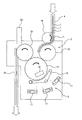
図1は、本発明の一実施形態に係る容器搬送装置を備えた容器検査装置を示す模式図である。図1に示すように、容器検査装置は、容器の一例であるプリフォーム1を搬送するための容器搬送装置2と、容器搬送装置2によって搬送されるプリフォーム1を検査する検査部3とを備えている。容器搬送装置2は、シュートレール4に接続されている。このシュートレール4の上流部は傾斜しており、プリフォーム1は、その首部に形成されたサポートリングがシュートレール4に支持された状態で、シュートレール4上を滑るようにして容器検査装置内に搬送される。シュートレール4の下流部は水平であり、下流部でのプリフォーム1はエアブロワ(図示せず)からの気流を受けてシュートレール4上を進む。
FIG. 1 is a schematic diagram showing a container inspection apparatus provided with a container transport device according to an embodiment of the present invention. As shown in FIG. 1, the container inspection apparatus includes a container conveyance device 2 for conveying a
容器搬送装置2は、シュートレール4に接続された入口ガイド7と、入口ガイド7に進入したプリフォーム1を所定間隔で1つずつ送るかき込みスターホイール10と、かき込みスターホイール10からプリフォーム1を受け取り、プリフォーム1をさらに移送する転送スターホイール12と、転送スターホイール12から受け渡されたプリフォーム1の口部を吸着ヘッドで真空吸着した状態でプリフォーム1を移送するメインロータ13と、プリフォーム1をメインロータ13から出口シュート21に移送する出口スターホイール20とを備えている。
The container transport device 2 includes an
プリフォーム1は、シュートレール4を通って容器検査装置の入口ガイド7に移送される。入口ガイド7に進入したプリフォーム1は、かき込みスターホイール10によって所定の間隔に整列され、入口ガイド7に沿ってかき込みスターホイール10により送られる。プリフォーム1は、かき込みスターホイール10から転送スターホイール12に渡され、さらに転送スターホイール12からメインロータ13に渡される。
The
検査部3は、メインロータ13に保持されたプリフォーム1を撮像し、その外観を検査する。より具体的には、メインロータ13に保持されたプリフォーム1を、自転用タイミングベルト15によって回転させながら、照明器16によってプリフォーム1を照明し、この状態でプリフォーム1を、照明器16の反対側からカメラなどの撮像手段17で撮像することでプリフォーム1の外観を検査する。
The
検査後のプリフォーム1は出口スターホイール20によって出口シュート21に移送される。正常なプリフォームは出口スターホイール20により吸着保持されて出口シュート21に移送されるが、不良なプリフォームは不良品排出シュート22の位置で出口スターホイール20による吸着保持が解除され、不良品排出シュート22を通じて排出される。
The
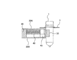
図2は、かき込みスターホイール10を示す上面図であり、図3は、図2のA−A線断面図であり、図4は、図2のB−B線断面図である。かき込みスターホイール10は、回転可能な支持部材30と、支持部材30の回転中心Oの周りに等間隔に配列された複数の可動爪(可動部材)33と、これら複数の可動爪33をそれぞれ独立に外方向に付勢する複数の付勢手段としての複数のばね40とを備えている。本実施形態では、支持部材30は、上側支持部材30Aおよび下側支持部材30Bを有する。入口ガイド7の下流部は、かき込みスターホイール10の周縁部に沿って延びている。
2 is a top view showing the stir-in
上側支持部材30Aおよび下側支持部材30Bは、互いに対向して配置されており、実質的に同じ形状を有している。上側支持部材30Aおよび下側支持部材30Bは、回転軸41に固定されており、この回転軸41と一体に回転するようになっている。したがって、上側支持部材30Aおよび下側支持部材30Bの回転中心Oは、回転軸41上に位置している。
The
複数の可動爪33は、上側支持部材30Aと下側支持部材30Bとの間に配置されている。上側支持部材30Aおよび下側支持部材30Bには、その回転中心Oの周りに配列された複数の支持軸45が固定されている。支持軸45は、回転中心Oの周りに等間隔に配列されていてもよい。各支持軸45の上端は上側支持部材30Aに固定され、各支持軸45の下端は下側支持部材30Bに固定されている。各可動爪33は各支持軸45にそれぞれ回動可能に支持されている。支持軸45の延びる方向は、上側支持部材30Aおよび下側支持部材30Bに対して垂直(すなわち、回転軸41の延びる方向と平行)である。
The plurality of
このような構成により、可動爪33は、支持部材30A,30Bの回転中心Oから離れる方向および回転中心Oに近づく方向に移動することが可能となっている。ばねホルダ49は、上側支持部材30Aおよび下側支持部材30Bに固定されている(図3参照)。ばねホルダ49に保持されたばね40は、可動爪33を回転中心Oから離れる方向に付勢している。
With such a configuration, the
図2に示すように、可動爪33は、上側支持部材30Aおよび下側支持部材30Bと一体に回転中心Oの周りを回転しながら、入口ガイド7に進入したプリフォーム1に接触し、プリフォーム1を1つずつ切り離し、そして、入口ガイド7に沿ってプリフォーム1を移送する。
As shown in FIG. 2, the
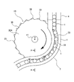
図5は、かき込みスターホイール10の内部構造を示す上面図である。図5では、上側支持部材30Aと下側支持部材30Bの図示は省略されている。図5に示すように、複数の可動爪33は、回転中心Oの周りに等間隔に配列されている。ばね40の一端は、各可動爪33に固定されたばねストッパ48に接続されており、ばね40の他端はばねホルダ49に保持されている。
FIG. 5 is a top view showing the internal structure of the
図5に示すように、ばね40は、可動爪33の数と同じ数だけ設けられ、一対一に対応付けられている。同様に、支持軸45は、可動爪33の数と同じ数だけ設けられ、一対一に対応付けられている。各ばね40は、対応する可動爪33を回転中心Oから離れる方向に向かって押圧している。この方向は、上側支持部材30Aおよび下側支持部材30Bの半径方向外側に向かう方向に概ね一致する。以下の説明では、回転中心Oから離れる方向を単に外方向といい、回転中心Oに向かう方向を内方向という。
As shown in FIG. 5, the same number of
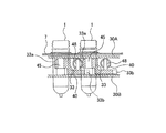
図6は、かき込みスターホイール10の可動爪33を示す拡大図である。図6に示すように、各可動爪33の一方の端部33aは、対応する支持軸45に回動可能に支持されており、各可動爪33の他端(先端)33bは、隣接する可動爪33を支持する支持軸45に当接している。より具体的には、可動爪33の一方の端部33aは、支持軸45の上半分に支持され、他端(先端)33bは、隣接する可動爪33を支持する支持軸45の下半分に当接する(図4参照)。
FIG. 6 is an enlarged view showing the
このような構成により、ばね40によって付勢された可動爪33の外方向への移動は、隣接する可動爪33を支持する支持軸45によって制限される。本実施形態では、可動爪33の外方向への移動を制限する制限部材は、隣接する可動爪33を支持する支持軸45によって構成されている。一実施形態では、可動爪33の外方向への移動を制限する制限部材は、支持軸45とは別の部材から構成されてもよい。
With such a configuration, the outward movement of the
可動爪33に大きな外力が加わると、図7に示すように、可動爪33はばね40の力に抗って内方向に変位する。ばね40および支持軸45は、可動爪33の数と同じだけ設けられている。したがって、各可動爪33は、他の可動爪33から独立して動くことができる。本実施形態では、付勢手段として、安定した付勢力を発生でき、耐久性が高く、コストが低いなどの観点から、ばね40が使用されているが、一実施形態では、付勢手段としてゴムなどの弾性材、またはエアシリンダを使用してもよい。
When a large external force is applied to the
各可動爪33は、プリフォーム1に接触する接触部33cを有している。プリフォーム1の胴部は、この接触部33cで押されることにより、入口ガイド7に沿って搬送される。本実施形態では、接触部33cは、プリフォーム1の胴部の形状に沿った湾曲形状を有しているが、他の形状を有してもよい。
Each
プリフォーム1が正常に搬送されているときは、プリフォーム1から受ける反力は小さいので、ばね40の力はその反力に勝り、可動爪33は外方向に押し出された状態を維持する。したがって、図5に示すように、かき込みスターホイール10は、入口ガイド7に移送されたプリフォーム1を可動爪33で1つずつ切り離しながら、入口ガイド7に沿ってプリフォーム1を1つずつ可動爪33で搬送することができる。
When the
図8に示すように、シュートレール4から搬送されるプリフォーム1の流れが悪くなるなどの理由により、プリフォーム1が入口ガイド7の導入部で停滞すると、プリフォーム1は、かき込みスターホイール10の可動爪33と入口ガイド7との間に挟まれる。このとき、プリフォーム1から受ける反力は通常よりも大きくなる。この反力がばね40の力よりも大きくなったとき、可動爪33はばね40の力に抗して内方向に変位する。
As shown in FIG. 8, when the
このように、かき込みスターホイール10がプリフォーム1を噛み込みそうになったとき、可動爪33は内方向に逃げるので、プリフォーム1の噛み込みは発生しない。結果として、プリフォーム1の生産を停止することが回避され、プリフォーム1をバイパスラインへ流す作業も不要となる。また、プリフォーム1の噛み込みに起因したかき込みスターホイール10および/または入口ガイド7などのダメージを防止することができる。さらには、可動爪33が逃げることにより、プリフォーム1自体がダメージを受けることを防止することができる。
In this way, when the biting
上述した実施形態では、容器としてのプリフォーム1に接触してプリフォーム1を搬送する可動部材は可動爪33から構成されているが、本発明は上記実施形態には限定されず、可動部材が容器に接触して当該容器を搬送することができる形状であれば、可動部材は爪の形状でなくてもよい。
In the above-described embodiment, the movable member that contacts the
これまで本発明の実施形態について説明したが、本発明は上述の実施形態に限定されず、その技術思想の範囲内において、種々の異なる形態で実施されてよいことは勿論である。 Although the embodiment of the present invention has been described so far, the present invention is not limited to the above-described embodiment, and it is needless to say that the present invention may be implemented in various different forms within the scope of the technical idea.
1 プリフォーム
2 容器搬送装置
3 検査部
4 シュートレール
7 入口ガイド
10 かき込みスターホイール
12 転送スターホイール
13 メインロータ
15 自転用タイミングベルト
16 照明器
17 撮像手段
20 出口スターホイール
21 出口シュート
30 支持部材
30A 上側支持部材
30B 下側支持部材
33 可動爪(可動部材)
40 ばね
41 回転軸
45 支持軸
48 ばねストッパ
49 ばねホルダ
DESCRIPTION OF
40
Claims (1)
前記支持部材と一体に回転可能であり、かつ前記支持部材の回転中心から離れる方向および前記回転中心に近づく方向に移動可能であり、かつ容器に接触可能な複数の可動部材と、
前記複数の可動部材を前記回転中心から離れる方向にそれぞれ付勢する複数の付勢手段と、
前記支持部材に固定された複数の支持軸を備え、
前記複数の可動部材は、前記複数の支持軸にそれぞれ回動可能に支持されており、
各可動部材の一端は、対応する前記支持軸に回動可能に支持されており、当該可動部材の他端は、隣接する可動部材を支持する支持軸に接触していることを特徴とする容器搬送装置。 A rotatable support member;
A plurality of movable members capable of rotating integrally with the support member, movable in a direction away from the rotation center of the support member and in a direction approaching the rotation center, and capable of contacting the container;
A plurality of urging means for urging each of the plurality of movable members in a direction away from the rotation center ;
A plurality of support shafts fixed to the support member;
The plurality of movable members are rotatably supported by the plurality of support shafts,
One end of each movable member is rotatably supported by the corresponding support shaft, and the other end of the movable member is in contact with a support shaft that supports an adjacent movable member. Conveying device.
Priority Applications (1)
| Application Number | Priority Date | Filing Date | Title |
|---|---|---|---|
| JP2015253952A JP6596643B2 (en) | 2015-12-25 | 2015-12-25 | Container transfer device |
Applications Claiming Priority (1)
| Application Number | Priority Date | Filing Date | Title |
|---|---|---|---|
| JP2015253952A JP6596643B2 (en) | 2015-12-25 | 2015-12-25 | Container transfer device |
Publications (2)
| Publication Number | Publication Date |
|---|---|
| JP2017114657A JP2017114657A (en) | 2017-06-29 |
| JP6596643B2 true JP6596643B2 (en) | 2019-10-30 |
Family
ID=59233125
Family Applications (1)
| Application Number | Title | Priority Date | Filing Date |
|---|---|---|---|
| JP2015253952A Active JP6596643B2 (en) | 2015-12-25 | 2015-12-25 | Container transfer device |
Country Status (1)
| Country | Link |
|---|---|
| JP (1) | JP6596643B2 (en) |
Families Citing this family (3)
| Publication number | Priority date | Publication date | Assignee | Title |
|---|---|---|---|---|
| DE102018005609A1 (en) * | 2018-07-17 | 2020-01-23 | Heuft Systemtechnik Gmbh | Transport device with rotating cylinder and clamping belt |
| IL268713B2 (en) * | 2019-08-14 | 2024-02-01 | Velox Puredigital Ltd | System and method for transferring and processing objects |
| CN115417066A (en) * | 2022-09-19 | 2022-12-02 | 昆明理工大学 | Tobacco leaf separating and conveying device based on vacuum adsorption conveying belt and self-adaptive storage bin |
Family Cites Families (4)
| Publication number | Priority date | Publication date | Assignee | Title |
|---|---|---|---|---|
| JPH10101193A (en) * | 1996-09-30 | 1998-04-21 | Shibuya Kogyo Co Ltd | Container grasping apparatus of rotary type filling machine |
| FR2772359B1 (en) * | 1997-12-16 | 2000-01-21 | Ads | TRANSFER WHEEL FOR PREFORMS OR CONTAINERS |
| US20030106778A1 (en) * | 2001-12-11 | 2003-06-12 | Hurst Richard Francis | Bottle indexing wheel with radially resilient teeth |
| ATE439320T1 (en) * | 2006-12-29 | 2009-08-15 | Sidel Holdings & Technology Sa | DEVICE FOR TRANSPORTING CONTAINERS OF NON-CIRCULAR SECTION |
-
2015
- 2015-12-25 JP JP2015253952A patent/JP6596643B2/en active Active
Also Published As
| Publication number | Publication date |
|---|---|
| JP2017114657A (en) | 2017-06-29 |
Similar Documents
| Publication | Publication Date | Title |
|---|---|---|
| JP6596643B2 (en) | Container transfer device | |
| US8646591B2 (en) | Apparatus for handling capsules and capsule processing equipment including such an apparatus | |
| US9352507B2 (en) | Separator device for preforms | |
| TW201720410A (en) | Tablet printing device | |
| JP2012509127A5 (en) | ||
| JP2012078120A (en) | Container cap inspection apparatus | |
| CN108430898B (en) | Device for receiving and conveying a stream of eggs | |
| TWI732600B (en) | Transporting apparatus and tablet printing apparatus | |
| TW201641001A (en) | Electronic component package carrier tape feeding method and device | |
| JP2023121822A (en) | Conveyance processing device and conveyance processing method | |
| JP6725795B2 (en) | Transport device | |
| JP6606655B2 (en) | Container transport device and inspection device provided with the container transport device | |
| JP4251242B2 (en) | PET bottle conveyor | |
| JP2012112835A (en) | Inspection apparatus of resin cap | |
| JP2007315794A (en) | Inspection device of molding container, and inspection method of the molding container | |
| JP2012025516A (en) | Transfer device and inspection apparatus for cap for vessel | |
| JP6735523B2 (en) | Tablet printing equipment | |
| CN105058748B (en) | A kind of claw for bottle discharging device | |
| CN105092601A (en) | Container erecting mechanism for automatic lamp inspection machine, and automatic lamp inspection machine | |
| JPH03248047A (en) | Method and apparatus for inspecting conveyed material | |
| WO2020085187A1 (en) | Transport device and transport method | |
| JP2004203598A (en) | Interval formation device for vessel | |
| JP7154596B2 (en) | Conveyor | |
| JP6782883B2 (en) | Transport equipment and inspection equipment | |
| JP2016000642A (en) | Inspection equipment container unloading method |
Legal Events
| Date | Code | Title | Description |
|---|---|---|---|
| A621 | Written request for application examination |
Free format text: JAPANESE INTERMEDIATE CODE: A621 Effective date: 20180912 |
|
| A977 | Report on retrieval |
Free format text: JAPANESE INTERMEDIATE CODE: A971007 Effective date: 20190614 |
|
| A131 | Notification of reasons for refusal |
Free format text: JAPANESE INTERMEDIATE CODE: A131 Effective date: 20190702 |
|
| A521 | Request for written amendment filed |
Free format text: JAPANESE INTERMEDIATE CODE: A523 Effective date: 20190808 |
|
| TRDD | Decision of grant or rejection written | ||
| A01 | Written decision to grant a patent or to grant a registration (utility model) |
Free format text: JAPANESE INTERMEDIATE CODE: A01 Effective date: 20190827 |
|
| A61 | First payment of annual fees (during grant procedure) |
Free format text: JAPANESE INTERMEDIATE CODE: A61 Effective date: 20190829 |
|
| R150 | Certificate of patent or registration of utility model |
Ref document number: 6596643 Country of ref document: JP Free format text: JAPANESE INTERMEDIATE CODE: R150 |
|
| R250 | Receipt of annual fees |
Free format text: JAPANESE INTERMEDIATE CODE: R250 |