JP6595258B2 - Lamp - Google Patents
Lamp Download PDFInfo
- Publication number
- JP6595258B2 JP6595258B2 JP2015167174A JP2015167174A JP6595258B2 JP 6595258 B2 JP6595258 B2 JP 6595258B2 JP 2015167174 A JP2015167174 A JP 2015167174A JP 2015167174 A JP2015167174 A JP 2015167174A JP 6595258 B2 JP6595258 B2 JP 6595258B2
- Authority
- JP
- Japan
- Prior art keywords
- projection lens
- light
- base plate
- shade
- light source
- Prior art date
- Legal status (The legal status is an assumption and is not a legal conclusion. Google has not performed a legal analysis and makes no representation as to the accuracy of the status listed.)
- Active
Links
Images


Classifications
-
- F—MECHANICAL ENGINEERING; LIGHTING; HEATING; WEAPONS; BLASTING
- F21—LIGHTING
- F21S—NON-PORTABLE LIGHTING DEVICES; SYSTEMS THEREOF; VEHICLE LIGHTING DEVICES SPECIALLY ADAPTED FOR VEHICLE EXTERIORS
- F21S41/00—Illuminating devices specially adapted for vehicle exteriors, e.g. headlamps
- F21S41/20—Illuminating devices specially adapted for vehicle exteriors, e.g. headlamps characterised by refractors, transparent cover plates, light guides or filters
- F21S41/25—Projection lenses
- F21S41/255—Lenses with a front view of circular or truncated circular outline
-
- F—MECHANICAL ENGINEERING; LIGHTING; HEATING; WEAPONS; BLASTING
- F21—LIGHTING
- F21S—NON-PORTABLE LIGHTING DEVICES; SYSTEMS THEREOF; VEHICLE LIGHTING DEVICES SPECIALLY ADAPTED FOR VEHICLE EXTERIORS
- F21S41/00—Illuminating devices specially adapted for vehicle exteriors, e.g. headlamps
- F21S41/10—Illuminating devices specially adapted for vehicle exteriors, e.g. headlamps characterised by the light source
- F21S41/14—Illuminating devices specially adapted for vehicle exteriors, e.g. headlamps characterised by the light source characterised by the type of light source
- F21S41/141—Light emitting diodes [LED]
- F21S41/147—Light emitting diodes [LED] the main emission direction of the LED being angled to the optical axis of the illuminating device
- F21S41/148—Light emitting diodes [LED] the main emission direction of the LED being angled to the optical axis of the illuminating device the main emission direction of the LED being perpendicular to the optical axis
-
- F—MECHANICAL ENGINEERING; LIGHTING; HEATING; WEAPONS; BLASTING
- F21—LIGHTING
- F21S—NON-PORTABLE LIGHTING DEVICES; SYSTEMS THEREOF; VEHICLE LIGHTING DEVICES SPECIALLY ADAPTED FOR VEHICLE EXTERIORS
- F21S41/00—Illuminating devices specially adapted for vehicle exteriors, e.g. headlamps
- F21S41/20—Illuminating devices specially adapted for vehicle exteriors, e.g. headlamps characterised by refractors, transparent cover plates, light guides or filters
- F21S41/29—Attachment thereof
- F21S41/295—Attachment thereof specially adapted to projection lenses
-
- F—MECHANICAL ENGINEERING; LIGHTING; HEATING; WEAPONS; BLASTING
- F21—LIGHTING
- F21S—NON-PORTABLE LIGHTING DEVICES; SYSTEMS THEREOF; VEHICLE LIGHTING DEVICES SPECIALLY ADAPTED FOR VEHICLE EXTERIORS
- F21S41/00—Illuminating devices specially adapted for vehicle exteriors, e.g. headlamps
- F21S41/30—Illuminating devices specially adapted for vehicle exteriors, e.g. headlamps characterised by reflectors
- F21S41/32—Optical layout thereof
- F21S41/321—Optical layout thereof the reflector being a surface of revolution or a planar surface, e.g. truncated
-
- F—MECHANICAL ENGINEERING; LIGHTING; HEATING; WEAPONS; BLASTING
- F21—LIGHTING
- F21S—NON-PORTABLE LIGHTING DEVICES; SYSTEMS THEREOF; VEHICLE LIGHTING DEVICES SPECIALLY ADAPTED FOR VEHICLE EXTERIORS
- F21S41/00—Illuminating devices specially adapted for vehicle exteriors, e.g. headlamps
- F21S41/30—Illuminating devices specially adapted for vehicle exteriors, e.g. headlamps characterised by reflectors
- F21S41/39—Attachment thereof
-
- F—MECHANICAL ENGINEERING; LIGHTING; HEATING; WEAPONS; BLASTING
- F21—LIGHTING
- F21S—NON-PORTABLE LIGHTING DEVICES; SYSTEMS THEREOF; VEHICLE LIGHTING DEVICES SPECIALLY ADAPTED FOR VEHICLE EXTERIORS
- F21S41/00—Illuminating devices specially adapted for vehicle exteriors, e.g. headlamps
- F21S41/40—Illuminating devices specially adapted for vehicle exteriors, e.g. headlamps characterised by screens, non-reflecting members, light-shielding members or fixed shades
- F21S41/43—Illuminating devices specially adapted for vehicle exteriors, e.g. headlamps characterised by screens, non-reflecting members, light-shielding members or fixed shades characterised by the shape thereof
-
- F—MECHANICAL ENGINEERING; LIGHTING; HEATING; WEAPONS; BLASTING
- F21—LIGHTING
- F21S—NON-PORTABLE LIGHTING DEVICES; SYSTEMS THEREOF; VEHICLE LIGHTING DEVICES SPECIALLY ADAPTED FOR VEHICLE EXTERIORS
- F21S45/00—Arrangements within vehicle lighting devices specially adapted for vehicle exteriors, for purposes other than emission or distribution of light
- F21S45/10—Protection of lighting devices
-
- F—MECHANICAL ENGINEERING; LIGHTING; HEATING; WEAPONS; BLASTING
- F21—LIGHTING
- F21S—NON-PORTABLE LIGHTING DEVICES; SYSTEMS THEREOF; VEHICLE LIGHTING DEVICES SPECIALLY ADAPTED FOR VEHICLE EXTERIORS
- F21S45/00—Arrangements within vehicle lighting devices specially adapted for vehicle exteriors, for purposes other than emission or distribution of light
- F21S45/40—Cooling of lighting devices
- F21S45/42—Forced cooling
- F21S45/43—Forced cooling using gas
- F21S45/435—Forced cooling using gas circulating the gas within a closed system
Description
本発明は、灯具に関する。 The present invention relates to a lamp.
灯具として、例えば、光源と当該光源から出射する光を透過させて所望の箇所に光を投射する投影レンズとを備えるものがある。このような灯具として、例えば、車両用灯具が挙げられる。 Some lamps include, for example, a light source and a projection lens that transmits light emitted from the light source and projects the light to a desired location. An example of such a lamp is a vehicular lamp.
下記特許文献1には、車両用灯具の一種である車両用前照灯に関する技術が開示されている。特許文献1に開示されている車両用前照灯は、レンズホルダ、レンズホルダに固定される投影レンズ、リフレクタ、及び、リフレクタで反射させて投影レンズに光を投射する光源等を備えている。この車両用前照灯において、光源には発光ダイオード(LED)が用いられている。光源として発光ダイオードが用いられる場合、ハロゲンランプやディスチャージドランプのような従来の光源に比べて発熱量が低減する。その結果、レンズホルダや投影レンズを樹脂で構成することが可能とされる。 Patent Document 1 listed below discloses a technique related to a vehicle headlamp that is a type of vehicle lamp. The vehicle headlamp disclosed in Patent Document 1 includes a lens holder, a projection lens fixed to the lens holder, a reflector, and a light source that reflects light from the reflector and projects light onto the projection lens. In this vehicle headlamp, a light emitting diode (LED) is used as a light source. When a light emitting diode is used as the light source, the amount of heat generation is reduced as compared with a conventional light source such as a halogen lamp or a discharged lamp. As a result, the lens holder and the projection lens can be made of resin.
上記のようにレンズホルダや投影レンズが樹脂で構成されることによって、灯具の軽量化や製造コストの低減等が図られる。その一方で、本発明者らは以下のような現象が生じる可能性を検討した。すなわち、灯具が屋外で利用される場合、投影レンズを通して外側から入射する太陽光が樹脂製のレンズホルダの一部に集光してレンズホルダが損傷される可能性について検討した。 Since the lens holder and the projection lens are made of resin as described above, the weight of the lamp can be reduced and the manufacturing cost can be reduced. On the other hand, the present inventors examined the possibility of the following phenomenon. That is, when the lamp is used outdoors, the possibility that sunlight incident from the outside through the projection lens is condensed on a part of the resin lens holder and the lens holder is damaged is examined.
本発明者らは、上記検討の結果、太陽光がレンズホルダに照射することを妨げる遮光部が投影レンズとレンズホルダとの間に設けられることによって、太陽光によるレンズホルダの損傷を抑制できることを見出した。 As a result of the above studies, the present inventors have found that a light-shielding portion that prevents sunlight from irradiating the lens holder is provided between the projection lens and the lens holder, so that damage to the lens holder due to sunlight can be suppressed. I found it.
そこで、本発明は、太陽光によるレンズホルダの損傷が抑制される灯具を提供しようとするものである。 Therefore, the present invention intends to provide a lamp in which damage to the lens holder due to sunlight is suppressed.
上記課題を解決するため、本発明の灯具は、光源と、一方の面に前記光源からの光が入射すると共に他方の面から前記光が出射する投影レンズと、前記投影レンズが固定され前記投影レンズから出射する前記光の方向とは反対側に延在するレンズホルダと、前記レンズホルダの前記投影レンズが固定される側とは反対側に配置され前記光源からの光が通る開口を有するベースプレートと、を備え、前記ベースプレートは前記投影レンズと前記レンズホルダとの間において前記投影レンズ側に延在する遮光部を有し、前記遮光部は前記ベースプレートの一部を折り曲げて形成されることを特徴とする。 In order to solve the above-described problems, a lamp according to the present invention includes a light source, a projection lens in which light from the light source is incident on one surface and the light is emitted from the other surface, and the projection lens is fixed to the projection lens. A base plate having a lens holder extending on a side opposite to the direction of the light emitted from the lens, and an opening arranged on a side opposite to the side on which the projection lens is fixed of the lens holder and through which the light from the light source passes. The base plate has a light shielding portion extending toward the projection lens between the projection lens and the lens holder, and the light shielding portion is formed by bending a part of the base plate. Features.
上記のように投影レンズとレンズホルダとの間に遮光部が備えられることによって、灯具の外側から投影レンズを通して入射する太陽光の少なくとも一部はレンズホルダに照射されずに遮光部に照射される。その結果、太陽光によるレンズホルダの損傷が抑制される。また、ベースプレートの一部が折り曲げられて遮光部が形成されることによって、灯具の製造コストの増大が抑制される。 By providing the light shielding part between the projection lens and the lens holder as described above, at least a part of the sunlight incident through the projection lens from the outside of the lamp is irradiated to the light shielding part without being irradiated to the lens holder. . As a result, damage to the lens holder due to sunlight is suppressed. Further, since the light shielding part is formed by bending a part of the base plate, an increase in the manufacturing cost of the lamp is suppressed.
また、前記ベースプレートの前記投影レンズが備えられる側とは反対側に、前記光源からの光の一部を遮るシェードが固定されることが好ましい。このようなシェードが備えられることによって、光源から出射される光が制御されて投影レンズに入射するので、投影レンズから出射する光を所望の配光パターンとすることができる。また、投影レンズとレンズホルダとの相対的位置が固定されており、シェードとベースプレートとの相対的位置も固定されているので、ベースプレートとレンズホルダとの相対的位置が固定されれば、投影レンズとシェードとの相対的位置が正確に決められる。その結果、所望の配光パターンが正確に形成され易くなる。 Moreover, it is preferable that a shade that blocks a part of the light from the light source is fixed to the side of the base plate opposite to the side on which the projection lens is provided. By providing such a shade, the light emitted from the light source is controlled and enters the projection lens, so that the light emitted from the projection lens can have a desired light distribution pattern. In addition, since the relative position between the projection lens and the lens holder is fixed, and the relative position between the shade and the base plate is also fixed, if the relative position between the base plate and the lens holder is fixed, the projection lens And the relative position of the shade are accurately determined. As a result, a desired light distribution pattern is easily formed accurately.
また、前記シェードは金型を用いて成型されることが好ましい。上記のようにシェードは光源からの光を制御する役割を有している。投影レンズから出射する光の配光パターンを正確にするためには、シェードの形状が精密である必要がある。シェードが金型を用いて成型されることによって高精度な形状のシェードが得られる。なお、ベースプレートとシェードとが金型で一体成型されることも可能であるが、特に精度が要求されるシェードは金型で成型されると共にベースプレートは板金等から成形されることによって、灯具の製造コストの増大が抑制される。 The shade is preferably molded using a mold. As described above, the shade has a role of controlling light from the light source. In order to make the light distribution pattern of the light emitted from the projection lens accurate, the shape of the shade needs to be precise. A highly accurate shade is obtained by molding the shade using a mold. Although the base plate and the shade can be integrally formed with a mold, a shade that requires particularly high precision is molded with a mold and the base plate is formed with a sheet metal to manufacture a lamp. Increase in cost is suppressed.
また、前記シェードと前記ベースプレートとが固定される固定部は、前記ベースプレートの一部が折り曲げられて前記遮光部が形成されるときにできる折り曲げ線に対して直交する方向に位置することが好ましい。ベースプレートの一部が折り曲げられて遮光部が形成されることによって、そのときにできる折り曲げ線に対して直交する方向では、その折り曲げ線に平行な方向の曲げ剛性が増す。従って、上記のような位置でシェードとベースプレートとが固定されることによって、シェードとベースプレートとが固定される際にベースプレートに加えられる力によってベースプレートが変形することが抑制される。その結果、シェードの設置位置がずれることが抑制される。 Moreover, it is preferable that the fixed part to which the shade and the base plate are fixed is located in a direction perpendicular to a folding line formed when a part of the base plate is bent to form the light shielding part. By bending a part of the base plate to form the light shielding portion, the bending rigidity in the direction parallel to the bending line is increased in the direction orthogonal to the bending line formed at that time. Therefore, by fixing the shade and the base plate at the position as described above, it is possible to prevent the base plate from being deformed by the force applied to the base plate when the shade and the base plate are fixed. As a result, it is suppressed that the installation position of the shade is shifted.
また、前記シェードは、前記光源から出射する光が前記投影レンズで反射されて照射される照射部を有し、前記照射部は前記投影レンズで反射されて照射される光の少なくとも一部を前記投影レンズに再び到達させないことが好ましい。光源から出射する光が投影レンズで反射されてシェードに照射され、シェードで反射して再び投影レンズを透過した場合、意図しない箇所に光が照射される虞がある。上記のようにシェードに照射される光の少なくとも一部が再び投影レンズに到達しないようにされることによって、意図しない光が投影レンズから出射することが抑制される。 The shade includes an irradiating unit that emits light emitted from the light source by being reflected by the projection lens, and the irradiating unit receives at least a part of the light that is reflected by the projecting lens and is emitted. It is preferable not to reach the projection lens again. When light emitted from the light source is reflected by the projection lens and applied to the shade, and reflected by the shade and transmitted through the projection lens again, there is a possibility that light is irradiated to an unintended location. By preventing at least a part of the light irradiated on the shade from reaching the projection lens again as described above, it is possible to prevent unintended light from being emitted from the projection lens.
また、前記照射部は前記投影レンズで反射されて照射される光の少なくとも一部を前記投影レンズに再び到達させないように反射させられる方向に延在することが好ましい。このような形状のシェードを作製することは容易なので、灯具の製造コストの増大が抑制されつつ、意図しない光が投影レンズから出射することが抑制される。 The irradiation unit preferably extends in a direction in which at least a part of light reflected and irradiated by the projection lens is reflected so as not to reach the projection lens again. Since it is easy to manufacture a shade having such a shape, an increase in the manufacturing cost of the lamp is suppressed, and unintended light is suppressed from being emitted from the projection lens.
以上のように、本発明によれば、太陽光によるレンズホルダの損傷が抑制される灯具が提供される。 As mentioned above, according to this invention, the lamp with which damage to the lens holder by sunlight is suppressed is provided.
以下、本発明に係る灯具の好適な実施形態について図面を参照しながら詳細に説明する。なお、各図において各部材の縮尺や寸法比等は実際とは異なる場合がある。 Hereinafter, a preferred embodiment of a lamp according to the present invention will be described in detail with reference to the drawings. In each figure, the scale and size ratio of each member may differ from the actual ones.
図1は本発明の実施形態に係る灯具の構成を概略的に示す断面図である。図1には、灯具の一例として車両用前照灯が示されている。図1に示す車両用前照灯1は、灯具ユニット2と、灯具ユニット2を収容する外筐3と、を備えている。以下、車両用前照灯1を構成するこれらの構成要素について詳細に説明する。
FIG. 1 is a cross-sectional view schematically showing a configuration of a lamp according to an embodiment of the present invention. FIG. 1 shows a vehicle headlamp as an example of a lamp. A vehicle headlamp 1 shown in FIG. 1 includes a
<外筐3>
外筐3は、ランプハウジング4及びフロントカバー5を有する。ランプハウジング4及びフロントカバー5によって形成される灯室3aに灯具ユニット2が収容される。ランプハウジング4は後述する光源11からの光が出射する側に開口を有する。フロントカバー5は、ランプハウジング4の当該開口を塞ぐように配置される。フロントカバー5は透光性を有する材料で構成されており、光源11から出射する光はフロントカバー5を透過する。また、ランプハウジング4は開孔4aを有している。開孔4aは灯具ユニット2の構成部品を交換する際に使用される。そして、外筐3はランプハウジング4の開孔4aを塞ぐバックカバー6を更に備えている。
<Outer casing 3>
The outer casing 3 has a
<灯具ユニット2>
図2は灯具ユニット2を示す斜視図である。また、図3は灯具ユニット2を構成する部材を示す分解斜視図である。図1から図3に示すように、灯具ユニット2は、光源ユニット10、リフレクタ20、ベースプレート30、シェード35、レンズホルダ40、及び、投影レンズ45を主な構成として備えている。
<
FIG. 2 is a perspective view showing the
(光源ユニット10)
光源ユニット10は、光源11、発光制御回路12、ヒートシンク13、及び冷却ファン15を備えている。本実施形態の車両用前照灯1において、光源11はLEDである。発光制御回路12は光源11の発光を制御する。ヒートシンク13はベース13a及び複数の放熱フィン13bを備えている。ベース13aは板状の部材であり、一方の面側には光源11及び発光制御回路12が載置され、他方の面側には放熱フィン13bが設けられる。また、ヒートシンク13の放熱フィン13bが設けられる側には、冷却ファン15が配置されている。光源11及び発光制御回路12が発する熱はヒートシンク13のベース13aから放熱フィン13bへと伝わり、放熱フィン13bが冷却ファン15によって冷却されることにより、効率良く光源ユニット10から熱が放出される。
(Light source unit 10)
The
(リフレクタ20)
リフレクタ20は光源11に被さるように設けられており、ねじ24によって光源ユニット10に固定されている。また、リフレクタ20は光源11と対向する面に反射面20aを有している。反射面20aは光源11の発光中心を第1焦点とする略楕円面状の曲面である。光源11から出射する光の少なくとも一部は反射面20aによって投影レンズ45側へ反射される。
(Reflector 20)
The
(投影レンズ45)
光源11から出射する光は上記のように反射面20aで反射され、投影レンズ45の一方の面45bに入射して他方の面45aから出射する。投影レンズ45は非球面平凸レンズであり、光源11からの光が入射する側の面である入射面45bは平面状であり、光源11からの光が出射する側の面である出射面45aは当該光の出射方向に膨らむ凸面状である。また、投影レンズ45は外周にフランジ部46を有している。そして、投影レンズ45は後側焦点を含む焦点面である後側焦点面上に形成される光源像を反転像として投影する。従って、後述するシェード35が当該後側焦点面上に配置されることによって、シェード35の形態に応じた配光パターンの光が投影レンズ45から出射される。
(Projection lens 45)
The light emitted from the
(レンズホルダ40)
レンズホルダ40は投影レンズ45を保持する部材である。投影レンズ45のフランジ部46がレンズホルダ40に固定される。上述したように光源11はLEDであり、ハロゲンランプやディスチャージドランプ等に比べて光源11からの発熱量が低減している。そのため、投影レンズ45及びレンズホルダ40をポリカーボネート等の樹脂で構成することが可能であり、本実施形態の車両用前照灯1では投影レンズ45及びレンズホルダ40は樹脂で構成される。投影レンズ45及びレンズホルダ40が樹脂で構成されることによって、投影レンズ45とレンズホルダ40とを溶着によって固定することができる。また、投影レンズ45及びレンズホルダ40が樹脂で構成されることによって、車両用前照灯1の軽量化や製造コストの低減を図ることができる。
(Lens holder 40)
The
レンズホルダ40は投影レンズ45側に備えられる筒状部41と、光源11側に備えられる一対の脚部42と、を有している。一対の脚部42は水平方向に並んで配置されている。図1から図3には一対の脚部42のうち一方のみが表れている。筒状部41は外形が円錐台状の中空部材であり、投影レンズ45から出射する上記光の方向とは反対側に向かって内径及び外径が広がりつつ延在する。筒状部41の投影レンズ45側の端部は上記のように投影レンズ45のフランジ部46に溶着される。また、一対の脚部42は筒状部41に連続して形成される部位である。一対の脚部42は投影レンズ45から出射する上記光の方向とは反対側に向かって脚部42同士の間隔が広がりつつ延在する。一対の脚部42のそれぞれの端部にはフランジ部43が形成されており、当該フランジ部43がねじ44によって光源ユニット10に固定される。
The
(ベースプレート30及びシェード35)
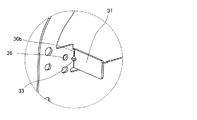
図4はベースプレート30とシェード35とを分解して示す斜視図である。図5は図4とは異なる方向から見たベースプレート30の斜視図である。図6はベースプレート30のうち図5に示すVIの部分を拡大して示す斜視図である。
(
FIG. 4 is an exploded perspective view showing the
ベースプレート30はねじ34,44によって光源ユニット10に固定され、レンズホルダ40と光源ユニット10との間に配置される。すなわち、ベースプレート30はレンズホルダ40の投影レンズ45が固定される側とは反対側に配置される。
The
ベースプレート30は光源11から出射する光が通る開口30aを有している。光源11から出射する光はベースプレート30の開口30aを通り、投影レンズ45に入射する。
The
また、ベースプレート30はベースプレート30の一部が折り曲げられて形成される板状の遮光部31を有している。遮光部31は投影レンズ45とレンズホルダ40との間において投影レンズ45側に延在している。より具体的には、遮光部31は水平方向に並んで二つ配置されおり、それぞれの遮光部31がレンズホルダ40の一対の脚部42のそれぞれと投影レンズ45との間において投影レンズ45側に延在している。このように遮光部31が備えられることによって、車両用前照灯1の外側から投影レンズ45を通して入射する太陽光の少なくとも一部はレンズホルダ40の脚部42に照射されずに遮光部31に照射される。その結果、太陽光によるレンズホルダ40の損傷が抑制される。例えば、投影レンズ45を通して入射する太陽光の焦点がレンズホルダ40上に形成される場合であっても、当該焦点へ太陽光が照射されることを遮光部31で遮ることによって、レンズホルダ40の損傷が抑制される。
The
また、別部材がベースプレート30に取り付けられて遮光部31が形成されるのではなく、ベースプレート30の一部が折り曲げられて遮光部31が形成されることによって、車両用前照灯1の製造コストの増大が抑制される。
In addition, a separate member is not attached to the
なお、遮光部31はレンズホルダ40から離間している。遮光部31とレンズホルダ40とが離間していることによって、遮光部31が太陽光から与えられた熱がレンズホルダ40に伝えられにくくなるので、レンズホルダ40が熱によって損傷することがより抑制され易くなる。
The
遮光部31は投影レンズ45を通して灯具ユニット2の外側から内側に入射する太陽光がレンズホルダ40に照射されることを抑制できる形態であれば良い。例えば、ベースプレート30の一部を直角に折り曲げることによって遮光部31が形成されても良く、レンズホルダ40の脚部42の内側の面に沿うように遮光部31が形成されても良い。
The light-shielding
また、ベースプレート30は、灯具ユニット2をランプハウジング4に取り付けるための取付部32を有する。取付部32は、灯具ユニット2を投影レンズ45側から見たときにベースプレート30が灯具ユニット2を構成する他の部材と重ならない位置に形成される貫通孔である。取付部32に通されるねじ(不図示)がランプハウジング4に形成されるねじ穴(不図示)に螺合されることによって、当該ねじの頭部とランプハウジング4とでベースプレート30が挟持されて固定され、灯具ユニット2がランプハウジング4に固定される。
Further, the
ベースプレート30を構成する材料は特に限定されない。ただし、ベースプレート30は太陽光を受ける遮光部31を有しているため、ベースプレート30は金属等の熱に強い材料で構成されることが好ましい。
The material constituting the
次にシェード35について説明する。シェード35は光源11からの光の一部を遮る部材である。シェード35はベースプレート30の投影レンズ45が配置される側とは反対側に固定される。光源11から出射する光がシェード35によって制御されて投影レンズ45に入射することにより、投影レンズ45から出射する光を所望の配光パターンとすることができる。光源11から出射する光はリフレクタ20で反射され、当該光の一部はシェード35に照射される。シェード35に照射される光のうち一部はシェード35によって遮蔽されて投影レンズ45に入射しない。また、シェード35に照射される光のうち他の一部はシェード35によって反射されて投影レンズ45に入射する。このとき、シェード35が所望の配光パターンに合わせた形態とされていることによって、所望のカットラインが形成されたりオーバーヘッドサインが形成されたりして、所望の配光パターンとなるように光が投影レンズ45に入射する。従って、シェード35の形態を適宜変更するだけで様々な配光パターンを形成することができる。
Next, the
上記のようにシェード35は投影レンズ45に入射する光源11からの光を制御する役割を有している。投影レンズ45から出射する光の配光パターンを正確にするためには、シェード35の形状が精密であることが好ましい。従って、シェード35は金型を用いて成型されることが好ましく、特にアルミダイキャストで成型されることが好ましい。シェード35が金型を用いて成型されることによって高精度な形状のシェード35が得られる。なお、ベースプレート30とシェード35とが金型で一体成型されることも可能であるが、特に精度が要求されるシェード35は金型で成型されると共にベースプレート30は板金等から成形されることによって、車両用前照灯1の製造コストの増大が抑制される。
As described above, the
上述したように投影レンズ45とレンズホルダ40とは固定されており、シェード35とベースプレート30とも固定されている。また、ベースプレート30はレンズホルダ40と光源ユニット10に挟まれて固定されることから、ベースプレート30とレンズホルダ40とも固定されるので、投影レンズ45とシェード35との相対的位置が正確に決められる。さらに、ベースプレート30及びリフレクタ20は光源ユニット10に固定されているので、光源11、リフレクタ20、シェード35、及び、投影レンズ45の相対的位置も正確に決められる。従って、本実施形態の車両用前照灯1によれば、光源11からシェード35を経て投影レンズ45へと入射する光を所望の経路通りに通すことが容易になり、所望の配光パターンを正確に形成することが容易になる。
As described above, the
シェード35とベースプレート30との固定方法は特に限定されないが、例えばカシメやねじ止めによって固定される。シェード35とベースプレート30とが固定される固定部36は、ベースプレート30の一部を折り曲げて遮光部31を形成するときにできる折り曲げ線30bに対して直交する方向に位置する。ベースプレート30の一部を折り曲げて遮光部31が形成されることによって、そのときにできる折り曲げ線30bに対して直交する方向では、その折り曲げ線30bに平行な方向の曲げ剛性が増す。従って、上記のような位置でシェード35とベースプレート30とが固定されることによって、シェード35とベースプレート30とが固定される際にベースプレート30に加えられる力によってベースプレート30が変形することが抑制される。ベースプレート30の変形が抑制されることにより、シェード35の位置がずれることが抑制される。従って、シェード35によって所望の配光パターンを正確に形成することがより容易になる。
The method for fixing the
なお、本実施形態の車両用前照灯1では、遮光部31の根元、すなわち折り曲げ線30bが形成される位置にビード33が形成されている。このようにビード33が形成されることによって、シェード35とベースプレート30とが固定される際のベースプレート30の変形がより抑制され易くなる。従って、シェード35の位置がずれることがより抑制され易くなり、シェード35によって所望の配光パターンを正確に形成することがより容易になる。
In the vehicle headlamp 1 of the present embodiment, the
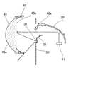
また、シェード35は、光源11から出射する光が投影レンズ45で反射されて照射される照射部37を有する。図7及び図8を参照しつつ照射部37について説明する。図7は灯具ユニット2を構成する一部の部材の切断面および光源11から出射する光の光路の例を示す図である。図7において光路の例は矢印で示されている。また、図8はシェード35の切断面を示す図である。
The
光源11から出射してリフレクタ20で反射されて投影レンズ45の入射面45bに達する光の多くは出射面45aから出射する。ただし、図7に示すように、光源11から出射してリフレクタ20で反射されて投影レンズ45の入射面45bに達する光の一部は入射面45bによってシェード35側に反射される場合がある。このように入射面45bによって反射される光の一部は、シェード35の照射部37に照射される。照射部37は入射面45bで反射されて照射される光の少なくとも一部を投影レンズ45に再び到達させない形態を有している。具体的には、照射部37は入射面45bに対して所定の角度θで傾斜して形成されている。図8に示す破線は入射面45bに平行な面を示している。このように照射部37が傾斜して形成されていることによって、投影レンズ45で反射されて照射部37に照射される光の少なくとも一部は投影レンズ45には入射しない方向に反射される。照射部37の入射面45bに対する傾斜角θは、投影レンズ45と照射部37との位置関係等によって適宜変更可能であるが、例えば10°程度とすることができる。
Most of the light emitted from the
光源11から出射する光が投影レンズ45で反射されてシェード35に照射され、シェード35で反射して再び投影レンズ45を透過した場合、意図しない箇所に光が照射される虞がある。上記のようにシェード35に照射される光の少なくとも一部が再び投影レンズ45に到達しないようにされることによって、意図しない光が投影レンズ45から出射することが抑制される。また、入射面45bに対して所定の角度θで傾斜している照射部37を有するシェード35を作製することは容易なので、本実施形態の車両用前照灯1によれば、製造コストの増大が抑制されつつ、意図しない光が投影レンズ45から出射することが抑制される。
When light emitted from the
以上、本発明について好適な実施形態を例に説明したが、本発明はこれに限定されるものではない。例えば、遮光部の形態は上述した例に限定されない。遮光部はベースプレートの一部を折り曲げて形成されており、レンズホルダに太陽光が照射されること抑制できる形態であれば良い。従って、遮光部の形状、大きさ、及び設置位置はレンズホルダの形状等に応じて適宜変更可能である。 As mentioned above, although preferred embodiment was described as an example about this invention, this invention is not limited to this. For example, the form of the light shielding part is not limited to the above-described example. The light-shielding part is formed by bending a part of the base plate, and may have any form that can suppress the lens holder from being irradiated with sunlight. Therefore, the shape, size, and installation position of the light shielding portion can be changed as appropriate according to the shape of the lens holder.
また、上記実施形態の車両用前照灯1ではシェード35がベースプレート30に固定される形態が例示されているが、本発明の灯具は係る形態に限定されない。シェードは、光源からシェードを経て投影レンズから出射される光の配光パターンを制御できる位置に配置されていればよく、ベースプレートに固定されていなくてもよい。
Moreover, although the form in which the
また、上記実施形態の車両用前照灯1ではシェード35が金型を用いて成型される形態が例示されているが、シェードの製造方法は特に限定されない。ただし、上述したようにシェードが金型で成型されることによってシェードの形状が精密になるので、シェードは金型を用いて成型されることが好ましい。
Moreover, in the vehicle headlamp 1 of the said embodiment, although the form in which the
また、上記実施形態の車両用前照灯1ではシェード35とベースプレート30とが固定される固定部36が折り曲げ線30bに対して直交する方向に位置する形態が例示されているが、シェードとベースプレートとが固定される位置は特に限定されない。ただし、上述したように、固定部36が折り曲げ線30bに対して直交する方向に位置することによって、シェード35がベースプレート30に固定されるときにベースプレート30の変形が抑制される。
Further, in the vehicle headlamp 1 of the above embodiment, the configuration in which the fixing
また、シェードの照射部の形態は上述した例に限定されない。照射部は、投影レンズで反射されて照射される光の少なくとも一部を投影レンズに再び到達させない形態であれば良い。すなわち、照射部は、投影レンズで反射されて照射される光の少なくとも一部を投影レンズに再び到達させないように反射させられる方向に延在していれば良く、途中で傾斜方向や傾斜角度が変わる形態であっても良い。また、照射部はローレット等のように照射される光を乱反射させる形状を有していても良く、光を吸収する色に塗装されていてもよい。 Moreover, the form of the irradiation part of a shade is not limited to the example mentioned above. The irradiation unit may be in any form that does not allow at least a part of the light reflected and irradiated by the projection lens to reach the projection lens again. In other words, the irradiation unit only needs to extend in a direction in which at least a part of the light reflected and irradiated by the projection lens is reflected so as not to reach the projection lens again. It may be a changed form. Moreover, the irradiation part may have a shape that diffusely reflects the irradiated light, such as knurls, and may be painted in a color that absorbs light.
また、投影レンズ及びレンズホルダを構成する材料は樹脂に限定されない。ただし、レンズホルダが熱に対して弱い樹脂等で構成されている場合に本発明の効果、すなわち、太陽光によるレンズホルダの損傷が抑制されるという効果をより顕著に得られる。また、投影レンズも樹脂で構成されることによって、投影レンズを樹脂からなるレンズホルダに溶着によって固定することが容易になる。 Moreover, the material which comprises a projection lens and a lens holder is not limited to resin. However, the effect of the present invention, that is, the effect that the damage of the lens holder due to sunlight is suppressed when the lens holder is made of heat-sensitive resin or the like can be obtained more remarkably. Further, since the projection lens is also made of resin, it becomes easy to fix the projection lens to the lens holder made of resin by welding.
また、本発明の灯具は車両用前照灯に限定されない。ただし、本発明の課題は太陽光によるレンズホルダの損傷を抑制することであるから、本発明の灯具は屋外での使用される可能性があるものである。従って、車両用前照灯のように太陽光が照射される屋外で使用される灯具に本発明の灯具が適用されることが好ましい。車両用前照灯以外の例としては、プロジェクタ等が挙げられる。 The lamp of the present invention is not limited to a vehicle headlamp. However, since the subject of this invention is suppressing the damage of the lens holder by sunlight, the lamp of this invention may be used outdoors. Therefore, it is preferable that the lamp of the present invention is applied to a lamp used outdoors such as a vehicle headlamp that is irradiated with sunlight. Examples other than the vehicle headlamp include a projector.
本発明によれば、太陽光によるレンズホルダの損傷が抑制される灯具が提供される。当該灯具は車両用前照灯等の屋外で利用される灯具に好適に利用される。 ADVANTAGE OF THE INVENTION According to this invention, the lamp with which damage to the lens holder by sunlight is suppressed is provided. The lamp is suitably used for a lamp used outdoors such as a vehicle headlamp.
1・・・車両用前照灯(灯具)
2・・・灯具ユニット
3・・・外筐
4・・・ランプハウジング
5・・・フロントカバー
6・・・バックカバー
10・・・光源ユニット
11・・・光源
12・・・発光制御回路
13・・・ヒートシンク
15・・・冷却ファン
20・・・リフレクタ
30・・・ベースプレート
30a・・・開口
30b・・・折り曲げ線
31・・・遮光部
35・・・シェード
36・・・固定部
37・・・照射部
40・・・レンズホルダ
45・・・投影レンズ
45a・・・出射面
45b・・・入射面
1 ... Vehicle headlamps
2 ... Lamp unit 3 ...
Claims (9)
一方の面に前記光源からの光が入射すると共に他方の面から前記光が出射する投影レンズと、
前記投影レンズが固定され前記投影レンズから出射する前記光の方向とは反対側に延在するレンズホルダと、
前記レンズホルダの前記投影レンズが固定される側とは反対側に配置され前記光源からの光が通る開口を有するベースプレートと、
を備え、
前記ベースプレートは、前記投影レンズと前記レンズホルダとの間において前記レンズホルダの内壁面に隣り合って設けられて前記投影レンズ側に延在する遮光部を有し、
前記遮光部は、前記ベースプレートの一部を折り曲げて形成され、灯具の外側から前記投影レンズを通して前記レンズホルダに進行する太陽光の少なくとも一部を遮光する
ことを特徴とする灯具。 A light source;
A projection lens in which light from the light source is incident on one surface and the light is emitted from the other surface;
A lens holder that is fixed to the projection lens and extends opposite to the direction of the light emitted from the projection lens;
A base plate disposed on the opposite side of the lens holder to the side on which the projection lens is fixed and having an opening through which light from the light source passes;
With
The base plate has a light blocking portion extending in the projection lens provided adjacent the inner wall of the lens holder between said lens holder and said projection lens,
The lamp , wherein the light-shielding part is formed by bending a part of the base plate, and shields at least part of sunlight that travels from the outside of the lamp to the lens holder through the projection lens .
ことを特徴とする請求項1に記載の灯具。 The lamp according to claim 1, wherein a shade that blocks a part of light from the light source is fixed to a side of the base plate opposite to a side on which the projection lens is provided.
ことを特徴とする請求項2に記載の灯具。 The lamp according to claim 2, wherein the shade is molded using a mold.
ことを特徴とする請求項2又は3に記載の灯具。 The fixing part to which the shade and the base plate are fixed is located in a direction orthogonal to a folding line formed when a part of the base plate is bent to form the light shielding part. Item 4. A lamp according to item 2 or 3.
前記照射部は前記投影レンズで反射されて照射される光の少なくとも一部を前記投影レンズに再び到達させない
ことを特徴とする請求項2から4のいずれか1項に記載の灯具。 The shade includes an irradiating unit that is irradiated with light emitted from the light source by being reflected by the projection lens;
5. The lamp according to claim 2, wherein the irradiation unit does not allow at least a part of the light reflected and irradiated by the projection lens to reach the projection lens again. 6.
ことを特徴とする請求項5に記載の灯具。 The lamp according to claim 5, wherein the irradiation unit extends in a direction in which at least a part of light reflected and irradiated by the projection lens is reflected so as not to reach the projection lens again.
傾斜する前記照射部は、前記入射面に直交する前記投影レンズの中心軸に直交する直交方向において前記投影レンズの中心軸から離れるにしたがって前記中心軸方向において前記入射面から離れて配置される The inclined irradiating unit is disposed away from the incident surface in the central axis direction as it is away from the central axis of the projection lens in an orthogonal direction orthogonal to the central axis of the projection lens orthogonal to the incident surface.
ことを特徴とする請求項6に記載の灯具。The lamp according to claim 6.
前記投影レンズ側に備えられ、前記投影レンズが固定される筒状部と、 A cylindrical portion provided on the projection lens side, to which the projection lens is fixed;
前記光源側に備えられ、前記筒状部に連続し、前記投影レンズから出射する前記光源からの前記光の出射方向とは反対側に延在し、並んで配置される一対の脚部と、 A pair of legs provided on the light source side, extending to the opposite side of the light emitting direction from the light source that is emitted from the projection lens, continuous with the cylindrical portion, and arranged side by side;
を備え、 With
前記遮光部は、対向して一対配置されており、 A pair of the light shielding portions are arranged opposite to each other,
一対の前記遮光部は、前記一対の脚部それぞれと前記投影レンズとの間において前記一対の脚部の内側の面に沿うように配置される The pair of light-shielding portions are arranged along the inner surfaces of the pair of leg portions between each of the pair of leg portions and the projection lens.
ことを特徴とする請求項1に記載の灯具。The lamp according to claim 1.
ことを特徴とする請求項1に記載の灯具。The lamp according to claim 1.
Priority Applications (5)
| Application Number | Priority Date | Filing Date | Title |
|---|---|---|---|
| JP2015167174A JP6595258B2 (en) | 2015-08-26 | 2015-08-26 | Lamp |
| DE102016216031.1A DE102016216031A1 (en) | 2015-08-26 | 2016-08-25 | lamp |
| FR1657923A FR3040468B1 (en) | 2015-08-26 | 2016-08-25 | LAMP |
| US15/247,301 US10125944B2 (en) | 2015-08-26 | 2016-08-25 | Lamp |
| CN201610730903.4A CN106482062B (en) | 2015-08-26 | 2016-08-26 | Lamps and lanterns |
Applications Claiming Priority (1)
| Application Number | Priority Date | Filing Date | Title |
|---|---|---|---|
| JP2015167174A JP6595258B2 (en) | 2015-08-26 | 2015-08-26 | Lamp |
Publications (2)
| Publication Number | Publication Date |
|---|---|
| JP2017045616A JP2017045616A (en) | 2017-03-02 |
| JP6595258B2 true JP6595258B2 (en) | 2019-10-23 |
Family
ID=58010694
Family Applications (1)
| Application Number | Title | Priority Date | Filing Date |
|---|---|---|---|
| JP2015167174A Active JP6595258B2 (en) | 2015-08-26 | 2015-08-26 | Lamp |
Country Status (5)
| Country | Link |
|---|---|
| US (1) | US10125944B2 (en) |
| JP (1) | JP6595258B2 (en) |
| CN (1) | CN106482062B (en) |
| DE (1) | DE102016216031A1 (en) |
| FR (1) | FR3040468B1 (en) |
Families Citing this family (12)
| Publication number | Priority date | Publication date | Assignee | Title |
|---|---|---|---|---|
| CN108916797B (en) * | 2017-03-31 | 2021-03-23 | 诚益光电科技股份有限公司 | Car light device and shielding plate structure thereof |
| CN207364902U (en) * | 2017-04-11 | 2018-05-15 | 法雷奥照明湖北技术中心有限公司 | Light emitting module and the motor vehicles including the light emitting module |
| US10544915B2 (en) * | 2017-04-27 | 2020-01-28 | Valeo North America, Inc. | Vehicle lamp assembly having an improved heat sink with light shield |
| JP2019046714A (en) * | 2017-09-05 | 2019-03-22 | 株式会社小糸製作所 | Lamp unit and vehicular lamp |
| EP3527875A1 (en) * | 2018-02-15 | 2019-08-21 | ZKW Group GmbH | Motor vehicle headlamp with a burning lens sheet |
| JP2019149284A (en) * | 2018-02-27 | 2019-09-05 | 株式会社小糸製作所 | Optical unit |
| JP2019194947A (en) * | 2018-05-01 | 2019-11-07 | 株式会社小糸製作所 | Lamp unit |
| CN111751952A (en) * | 2019-03-29 | 2020-10-09 | 三营超精密光电(晋城)有限公司 | Lens module and electronic device with same |
| CN110985990A (en) * | 2019-10-31 | 2020-04-10 | 江苏恒瑞车灯有限公司 | Adjusting and fixing device for lens of combined headlamp and combined headlamp |
| JP7351225B2 (en) * | 2020-01-07 | 2023-09-27 | 市光工業株式会社 | Vehicle lights |
| FR3137154A1 (en) * | 2022-06-22 | 2023-12-29 | Valeo Vision | AUTOMOBILE LIGHTING MODULE WITH PARTIALLY GRAINED SURFACE REFLECTOR |
| US11890984B1 (en) * | 2022-12-29 | 2024-02-06 | Sonar Auto Parts Co., Ltd. | Vehicle lamp having switching structure for low-beam and high-beam headlights |
Family Cites Families (13)
| Publication number | Priority date | Publication date | Assignee | Title |
|---|---|---|---|---|
| DE3540130C1 (en) | 1985-11-13 | 1987-04-02 | Hella Kg Hueck & Co | Headlights for motor vehicles |
| DE10217785C1 (en) | 2002-04-21 | 2003-10-16 | Matthias Brand | Light distribution module for automobile headlamp has variable light stop provided as part of carrier attached to headlamp reflector and supporting setting drive |
| JP2006253098A (en) | 2005-03-14 | 2006-09-21 | Koito Mfg Co Ltd | Vehicular headlamp |
| JP2009064713A (en) * | 2007-09-07 | 2009-03-26 | Koito Mfg Co Ltd | Vehicle headlight |
| JP5414246B2 (en) * | 2008-11-19 | 2014-02-12 | 株式会社小糸製作所 | Vehicle headlamp |
| JP5700818B2 (en) * | 2011-05-30 | 2015-04-15 | 株式会社小糸製作所 | Vehicle headlamp |
| FR2983279B1 (en) | 2011-11-24 | 2015-08-21 | Valeo Vision | OPAQUE AND MOBILE ELEMENT PREVENTING THE FOCUSING OF SOLAR RAYS IN A PROJECTOR |
| KR101460729B1 (en) | 2012-05-02 | 2014-11-12 | 현대모비스 주식회사 | Lamp apparatus for an automobile |
| JP5977111B2 (en) * | 2012-07-31 | 2016-08-24 | 株式会社小糸製作所 | Vehicle headlamp |
| JPWO2014057863A1 (en) * | 2012-10-09 | 2016-09-05 | 株式会社小糸製作所 | Vehicle lighting |
| JP6147510B2 (en) | 2013-01-28 | 2017-06-14 | 株式会社小糸製作所 | Vehicle headlamp |
| CN203857382U (en) | 2014-05-23 | 2014-10-01 | 上海通用汽车有限公司 | Vehicle lens-type headlamp decorative ring and lens-type headlamp |
| JP6510330B2 (en) * | 2015-06-10 | 2019-05-08 | 株式会社小糸製作所 | Vehicle lighting system |
-
2015
- 2015-08-26 JP JP2015167174A patent/JP6595258B2/en active Active
-
2016
- 2016-08-25 DE DE102016216031.1A patent/DE102016216031A1/en not_active Withdrawn
- 2016-08-25 FR FR1657923A patent/FR3040468B1/en not_active Expired - Fee Related
- 2016-08-25 US US15/247,301 patent/US10125944B2/en active Active
- 2016-08-26 CN CN201610730903.4A patent/CN106482062B/en active Active
Also Published As
| Publication number | Publication date |
|---|---|
| DE102016216031A1 (en) | 2017-03-02 |
| CN106482062A (en) | 2017-03-08 |
| US20170059109A1 (en) | 2017-03-02 |
| FR3040468B1 (en) | 2018-11-16 |
| FR3040468A1 (en) | 2017-03-03 |
| US10125944B2 (en) | 2018-11-13 |
| CN106482062B (en) | 2019-09-06 |
| JP2017045616A (en) | 2017-03-02 |
Similar Documents
| Publication | Publication Date | Title |
|---|---|---|
| JP6595258B2 (en) | Lamp | |
| JP6061638B2 (en) | Vehicle lighting | |
| JP6441823B2 (en) | Vehicle lighting | |
| EP2719941B1 (en) | Vehicular headlamp comprising a projection lens | |
| JP5666882B2 (en) | High beam lamp unit | |
| JP2010080075A (en) | Lighting fixture for vehicle | |
| JP2008226706A (en) | Vehicle lamp | |
| JP2009064729A (en) | Lighting fixture unit for vehicle | |
| JP6709802B2 (en) | Vehicle lighting | |
| EP2518393B1 (en) | Vehicular lamp | |
| CN107543116B (en) | Vehicle headlamp and light source unit | |
| JP2011082005A (en) | Lighting fixture for vehicle | |
| JP2010272422A (en) | Vehicular lighting fixture | |
| JP6764257B2 (en) | Vehicle lighting | |
| JP2017212169A (en) | Vehicular lighting fixture | |
| JP2011181279A (en) | Headlight for vehicle | |
| JP5435213B2 (en) | Vehicle lighting | |
| JP2017208208A (en) | Lamp | |
| JP6078276B2 (en) | Lamp unit | |
| US9482400B2 (en) | Light-emitting device for a motor vehicle headlamp and headlamp equipped with said device | |
| JP2017010639A (en) | Vehicle headlamp | |
| JP6575344B2 (en) | Vehicle lighting | |
| JP7183876B2 (en) | lighting equipment | |
| JP7354570B2 (en) | Vehicle lights | |
| JP6155714B2 (en) | Vehicle lighting |
Legal Events
| Date | Code | Title | Description |
|---|---|---|---|
| A621 | Written request for application examination |
Free format text: JAPANESE INTERMEDIATE CODE: A621 Effective date: 20180706 |
|
| A131 | Notification of reasons for refusal |
Free format text: JAPANESE INTERMEDIATE CODE: A131 Effective date: 20190507 |
|
| A977 | Report on retrieval |
Free format text: JAPANESE INTERMEDIATE CODE: A971007 Effective date: 20190425 |
|
| A521 | Written amendment |
Free format text: JAPANESE INTERMEDIATE CODE: A523 Effective date: 20190628 |
|
| TRDD | Decision of grant or rejection written | ||
| A01 | Written decision to grant a patent or to grant a registration (utility model) |
Free format text: JAPANESE INTERMEDIATE CODE: A01 Effective date: 20190903 |
|
| A61 | First payment of annual fees (during grant procedure) |
Free format text: JAPANESE INTERMEDIATE CODE: A61 Effective date: 20190926 |
|
| R150 | Certificate of patent or registration of utility model |
Ref document number: 6595258 Country of ref document: JP Free format text: JAPANESE INTERMEDIATE CODE: R150 |