JP6595161B2 - Image processing apparatus, image processing method, and imaging apparatus - Google Patents
Image processing apparatus, image processing method, and imaging apparatus Download PDFInfo
- Publication number
- JP6595161B2 JP6595161B2 JP2014155662A JP2014155662A JP6595161B2 JP 6595161 B2 JP6595161 B2 JP 6595161B2 JP 2014155662 A JP2014155662 A JP 2014155662A JP 2014155662 A JP2014155662 A JP 2014155662A JP 6595161 B2 JP6595161 B2 JP 6595161B2
- Authority
- JP
- Japan
- Prior art keywords
- filter
- image
- color
- color filter
- observation
- Prior art date
- Legal status (The legal status is an assumption and is not a legal conclusion. Google has not performed a legal analysis and makes no representation as to the accuracy of the status listed.)
- Active
Links
- 238000012545 processing Methods 0.000 title claims description 106
- 238000003384 imaging method Methods 0.000 title claims description 18
- 238000003672 processing method Methods 0.000 title claims description 10
- 238000000034 method Methods 0.000 claims description 37
- 239000011159 matrix material Substances 0.000 claims description 23
- 239000003086 colorant Substances 0.000 claims description 20
- 230000006835 compression Effects 0.000 claims description 11
- 238000007906 compression Methods 0.000 claims description 11
- 238000006243 chemical reaction Methods 0.000 claims description 8
- 108091006146 Channels Proteins 0.000 description 20
- 238000005516 engineering process Methods 0.000 description 14
- 230000006870 function Effects 0.000 description 10
- 230000000295 complement effect Effects 0.000 description 6
- 239000000654 additive Substances 0.000 description 4
- 230000000996 additive effect Effects 0.000 description 4
- 239000012466 permeate Substances 0.000 description 4
- 238000010586 diagram Methods 0.000 description 3
- 238000005070 sampling Methods 0.000 description 3
- 239000004065 semiconductor Substances 0.000 description 3
- 230000006837 decompression Effects 0.000 description 2
- 230000000694 effects Effects 0.000 description 2
- 238000005401 electroluminescence Methods 0.000 description 2
- 230000010365 information processing Effects 0.000 description 2
- 230000002093 peripheral effect Effects 0.000 description 2
- 238000004891 communication Methods 0.000 description 1
- 238000007796 conventional method Methods 0.000 description 1
- 239000004973 liquid crystal related substance Substances 0.000 description 1
- 229910044991 metal oxide Inorganic materials 0.000 description 1
- 150000004706 metal oxides Chemical class 0.000 description 1
- 238000012986 modification Methods 0.000 description 1
- 230000004048 modification Effects 0.000 description 1
- 230000003287 optical effect Effects 0.000 description 1
- 230000005855 radiation Effects 0.000 description 1
Images


Classifications
-
- H—ELECTRICITY
- H01—ELECTRIC ELEMENTS
- H01L—SEMICONDUCTOR DEVICES NOT COVERED BY CLASS H10
- H01L27/00—Devices consisting of a plurality of semiconductor or other solid-state components formed in or on a common substrate
- H01L27/14—Devices consisting of a plurality of semiconductor or other solid-state components formed in or on a common substrate including semiconductor components sensitive to infrared radiation, light, electromagnetic radiation of shorter wavelength or corpuscular radiation and specially adapted either for the conversion of the energy of such radiation into electrical energy or for the control of electrical energy by such radiation
- H01L27/144—Devices controlled by radiation
- H01L27/146—Imager structures
- H01L27/14601—Structural or functional details thereof
- H01L27/1462—Coatings
- H01L27/14621—Colour filter arrangements
-
- H—ELECTRICITY
- H04—ELECTRIC COMMUNICATION TECHNIQUE
- H04N—PICTORIAL COMMUNICATION, e.g. TELEVISION
- H04N13/00—Stereoscopic video systems; Multi-view video systems; Details thereof
- H04N13/20—Image signal generators
- H04N13/204—Image signal generators using stereoscopic image cameras
- H04N13/207—Image signal generators using stereoscopic image cameras using a single 2D image sensor
- H04N13/214—Image signal generators using stereoscopic image cameras using a single 2D image sensor using spectral multiplexing
-
- G—PHYSICS
- G02—OPTICS
- G02B—OPTICAL ELEMENTS, SYSTEMS OR APPARATUS
- G02B5/00—Optical elements other than lenses
- G02B5/20—Filters
- G02B5/201—Filters in the form of arrays
-
- G—PHYSICS
- G02—OPTICS
- G02B—OPTICAL ELEMENTS, SYSTEMS OR APPARATUS
- G02B5/00—Optical elements other than lenses
- G02B5/20—Filters
- G02B5/208—Filters for use with infrared or ultraviolet radiation, e.g. for separating visible light from infrared and/or ultraviolet radiation
-
- H—ELECTRICITY
- H04—ELECTRIC COMMUNICATION TECHNIQUE
- H04N—PICTORIAL COMMUNICATION, e.g. TELEVISION
- H04N23/00—Cameras or camera modules comprising electronic image sensors; Control thereof
- H04N23/10—Cameras or camera modules comprising electronic image sensors; Control thereof for generating image signals from different wavelengths
-
- H—ELECTRICITY
- H04—ELECTRIC COMMUNICATION TECHNIQUE
- H04N—PICTORIAL COMMUNICATION, e.g. TELEVISION
- H04N25/00—Circuitry of solid-state image sensors [SSIS]; Control thereof
- H04N25/10—Circuitry of solid-state image sensors [SSIS]; Control thereof for transforming different wavelengths into image signals
- H04N25/11—Arrangement of colour filter arrays [CFA]; Filter mosaics
- H04N25/13—Arrangement of colour filter arrays [CFA]; Filter mosaics characterised by the spectral characteristics of the filter elements
- H04N25/131—Arrangement of colour filter arrays [CFA]; Filter mosaics characterised by the spectral characteristics of the filter elements including elements passing infrared wavelengths
-
- H—ELECTRICITY
- H04—ELECTRIC COMMUNICATION TECHNIQUE
- H04N—PICTORIAL COMMUNICATION, e.g. TELEVISION
- H04N25/00—Circuitry of solid-state image sensors [SSIS]; Control thereof
- H04N25/10—Circuitry of solid-state image sensors [SSIS]; Control thereof for transforming different wavelengths into image signals
- H04N25/11—Arrangement of colour filter arrays [CFA]; Filter mosaics
- H04N25/13—Arrangement of colour filter arrays [CFA]; Filter mosaics characterised by the spectral characteristics of the filter elements
- H04N25/133—Arrangement of colour filter arrays [CFA]; Filter mosaics characterised by the spectral characteristics of the filter elements including elements passing panchromatic light, e.g. filters passing white light
-
- H—ELECTRICITY
- H04—ELECTRIC COMMUNICATION TECHNIQUE
- H04N—PICTORIAL COMMUNICATION, e.g. TELEVISION
- H04N25/00—Circuitry of solid-state image sensors [SSIS]; Control thereof
- H04N25/10—Circuitry of solid-state image sensors [SSIS]; Control thereof for transforming different wavelengths into image signals
- H04N25/11—Arrangement of colour filter arrays [CFA]; Filter mosaics
- H04N25/13—Arrangement of colour filter arrays [CFA]; Filter mosaics characterised by the spectral characteristics of the filter elements
- H04N25/134—Arrangement of colour filter arrays [CFA]; Filter mosaics characterised by the spectral characteristics of the filter elements based on three different wavelength filter elements
-
- H—ELECTRICITY
- H04—ELECTRIC COMMUNICATION TECHNIQUE
- H04N—PICTORIAL COMMUNICATION, e.g. TELEVISION
- H04N25/00—Circuitry of solid-state image sensors [SSIS]; Control thereof
- H04N25/10—Circuitry of solid-state image sensors [SSIS]; Control thereof for transforming different wavelengths into image signals
- H04N25/11—Arrangement of colour filter arrays [CFA]; Filter mosaics
- H04N25/13—Arrangement of colour filter arrays [CFA]; Filter mosaics characterised by the spectral characteristics of the filter elements
- H04N25/135—Arrangement of colour filter arrays [CFA]; Filter mosaics characterised by the spectral characteristics of the filter elements based on four or more different wavelength filter elements
-
- G—PHYSICS
- G06—COMPUTING; CALCULATING OR COUNTING
- G06T—IMAGE DATA PROCESSING OR GENERATION, IN GENERAL
- G06T7/00—Image analysis
- G06T7/50—Depth or shape recovery
Description
本技術は、画像処理装置、画像処理方法、及び、撮像装置に関し、特に、受光面への十分な入射光量を確保してS/N比を改善しつつ、モアレを軽減することができるようにした画像処理装置、画像処理方法、及び、撮像装置に関する。 The present technology relates to an image processing device, an image processing method, and an imaging device, and in particular, can secure a sufficient amount of incident light on a light receiving surface to improve a S / N ratio and reduce moire. The present invention relates to an image processing apparatus, an image processing method, and an imaging apparatus.
従来、イメージセンサを使用して、被写体の画像を取得しつつ、パッシブに奥行き情報を得る方法として、レンズ部の開口部にカラーフィルタを設けたColor-Filtered Apertureと呼ばれる技術が提案されている(例えば、非特許文献1参照)。特許文献1には、Color-Filtered Apertureの原理を利用して、シーンの奥行きを推定する方法が開示されている。 Conventionally, a technique called Color-Filtered Aperture in which a color filter is provided at the opening of a lens unit has been proposed as a method for passively obtaining depth information while acquiring an image of a subject using an image sensor ( For example, refer nonpatent literature 1). Patent Document 1 discloses a method for estimating the depth of a scene using the principle of Color-Filtered Aperture.
ところで、従来の技術であると、レンズ部に入射した光が、当該レンズ部の開口部に設けられたカラーフィルタの4分割された領域のうち、1つの領域しか透過しないため、その光量が1/4となって、S/N比(Signal to Noise Ratio)が悪化していた。同様にまた、レンズ部に入射した光が、カラーフィルタの1つの領域しか透過しないため、その解像度が縦横で半分になって、モアレが発生する恐れがあった。 By the way, according to the conventional technique, the light incident on the lens portion transmits only one region among the four divided regions of the color filter provided at the opening of the lens portion, and thus the light amount is 1 / 4, and the S / N ratio (Signal to Noise Ratio) was deteriorated. Similarly, since the light incident on the lens part transmits only one area of the color filter, the resolution is halved in the vertical and horizontal directions, and moire may occur.
そのため、Color-Filtered Apertureの原理を利用した場合において、受光面への十分な入射光量を確保してS/N比を改善しつつ、モアレを軽減するための技術が求められていた。 Therefore, when the principle of Color-Filtered Aperture is used, a technique for reducing the moire while ensuring a sufficient amount of incident light on the light receiving surface and improving the S / N ratio has been demanded.
本技術はこのような状況に鑑みてなされたものであり、受光面への十分な入射光量を確保してS/N比を改善しつつ、モアレを軽減することができるようにするものである。 The present technology has been made in view of such a situation, and is capable of reducing moiré while securing a sufficient amount of incident light on the light receiving surface to improve the S / N ratio. .
本技術の一側面の画像処理装置は、被写体からの光を集光するレンズ部と、前記レンズ部の開口部に配置され、所定の特性を有する第1のカラーフィルタと、前記レンズ部からの光を光電変換して、画像信号として出力するイメージセンサと、前記イメージセンサの前面に配置され、前記第1のカラーフィルタと異なる特性を有するとともに、各色がランダムに配列された第2のカラーフィルタと、前記イメージセンサから出力される前記画像信号に対して圧縮センシングを適用することで、前記被写体の画像を復元する画像処理部とを備え、前記第1のカラーフィルタは、シアン(Cy)、マゼンタ(Mg)、黄(Ye)、白(W)の各色からなるフィルタであり、前記第2のカラーフィルタは、赤(R)、緑(G)、青(B)の各色と、赤外線光を透過させることが可能なIR(Infrared Ray)パスフィルタからなるフィルタであり、前記圧縮センシングにおいては、前記第1のカラーフィルタと前記第2のカラーフィルタを通る過程が観測行列とされ、色チャンネルごとの前記観測行列と観測画像を用いて、各色チャンネルにおける前記被写体の画像の復元処理が行われ、前記観測画像は、前記シアン(Cy)のフィルタを透過した光が、前記緑(G)、前記青(B)のフィルタと前記IRパスフィルタをさらに透過することで得られる第1の観測画像と、前記マゼンタ(Mg)のフィルタを透過した光が、前記赤(R)、前記青(B)のフィルタと前記IRパスフィルタをさらに透過することで得られる第2の観測画像と、前記黄(Ye)のフィルタを透過した光が、前記赤(R)、前記緑(G)のフィルタと前記IRパスフィルタをさらに透過することで得られる第3の観測画像と、前記白(W)のフィルタを透過した光が、前記赤(R)、前記緑(G)、前記青(B)のフィルタと前記IRパスフィルタをさらに透過することで得られる第4の観測画像とを含む画像処理装置である。 An image processing apparatus according to an aspect of the present technology includes a lens unit that collects light from a subject, a first color filter that is disposed in an opening of the lens unit and has predetermined characteristics, and An image sensor that photoelectrically converts light and outputs it as an image signal, and a second color filter that is disposed in front of the image sensor and has characteristics different from those of the first color filter and in which each color is randomly arranged And an image processing unit that restores the image of the subject by applying compression sensing to the image signal output from the image sensor, wherein the first color filter is cyan (Cy), magenta (Mg), a filter composed of the respective colors of yellow (Ye), white (W), the second color filter, and each color of red (R), green (G), and blue (B), Ri filter Der consisting capable IR (Infrared Ray) pass filter that transmits the external light, in the compressed sensing, a process through the first color filter and the second color filter is the observation matrix Then, using the observation matrix and the observation image for each color channel, restoration processing of the image of the subject in each color channel is performed. In the observation image, the light transmitted through the cyan (Cy) filter is converted into the green ( G), the first observation image obtained by further passing through the blue (B) filter and the IR path filter, and the light transmitted through the magenta (Mg) filter are the red (R), The second observation image obtained by further passing through the blue (B) filter and the IR path filter, and the light transmitted through the yellow (Ye) filter are converted into the red ( ), A third observation image obtained by further passing through the green (G) filter and the IR path filter, and light transmitted through the white (W) filter are the red (R) and green (G) An image processing apparatus including the blue (B) filter and a fourth observation image obtained by further passing through the IR path filter .
前記画像処理部は、前記イメージセンサから出力される画像信号に対して所定の画像処理を施すことで得られる視差情報を用いて、奥行き情報を算出することができる。 The image processing unit can calculate depth information using parallax information obtained by performing predetermined image processing on an image signal output from the image sensor.
前記画像処理装置は、独立した装置であってもよいし、1つの装置を構成している内部ブロックであってもよい。 The image processing apparatus may be an independent apparatus or an internal block constituting one apparatus.
本技術の一側面の画像処理方法は、画像処理装置の画像処理方法において、前記画像処理装置が、所定の特性を有する第1のカラーフィルタが開口部に配置されるレンズ部であって被写体からの光を集光する前記レンズ部からの光が、前記第1のカラーフィルタと異なる特性を有するとともに各色がランダムに配列された第2のカラーフィルタが前面に配置されるイメージセンサにより光電変換されることで得られる画像信号に対して圧縮センシングを適用することで、前記被写体の画像を復元するステップを含み、前記第1のカラーフィルタは、シアン(Cy)、マゼンタ(Mg)、黄(Ye)、白(W)の各色からなるフィルタであり、前記第2のカラーフィルタは、赤(R)、緑(G)、青(B)の各色と、赤外線光を透過させることが可能なIRパスフィルタからなるフィルタであり、前記圧縮センシングにおいては、前記第1のカラーフィルタと前記第2のカラーフィルタを通る過程が観測行列とされ、色チャンネルごとの前記観測行列と観測画像を用いて、各色チャンネルにおける前記被写体の画像の復元処理が行われ、前記観測画像は、前記シアン(Cy)のフィルタを透過した光が、前記緑(G)、前記青(B)のフィルタと前記IRパスフィルタをさらに透過することで得られる第1の観測画像と、前記マゼンタ(Mg)のフィルタを透過した光が、前記赤(R)、前記青(B)のフィルタと前記IRパスフィルタをさらに透過することで得られる第2の観測画像と、前記黄(Ye)のフィルタを透過した光が、前記赤(R)、前記緑(G)のフィルタと前記IRパスフィルタをさらに透過することで得られる第3の観測画像と、前記白(W)のフィルタを透過した光が、前記赤(R)、前記緑(G)、前記青(B)のフィルタと前記IRパスフィルタをさらに透過することで得られる第4の観測画像とを含む画像処理方法である。 According to an image processing method of an aspect of the present technology, in the image processing method of the image processing device, the image processing device is a lens unit in which a first color filter having a predetermined characteristic is disposed in an opening, and The light from the lens unit that collects the light of the first color is photoelectrically converted by an image sensor having a second color filter having a different characteristic from the first color filter and randomly arranged in each color. And applying the compressed sensing to the image signal obtained by the above-described processing, thereby restoring the image of the subject. The first color filter includes cyan (Cy), magenta (Mg), yellow (Ye). ) is a filter consisting of the colors of white (W), the second color filter is red (R), green (G), and the respective colors of blue (B), that transmits infrared radiation beam Ri filter Der consisting capable IR pass filter, in the compressed sensing, the first color filter and the process of passing through the second color filter is the observation matrix, the observation matrix and the observed image of each color channel Is used to restore the image of the subject in each color channel, and the observed image includes light transmitted through the cyan (Cy) filter and the green (G) and blue (B) filters. The first observation image obtained by further passing through the IR pass filter, and the light transmitted through the magenta (Mg) filter are the red (R), blue (B) filters, and the IR pass filter. The second observation image obtained by further transmitting the light and the light transmitted through the yellow (Ye) filter are the red (R) and green (G) filters and the I The third observation image obtained by further passing through the pass filter and the light transmitted through the white (W) filter are the red (R), green (G), and blue (B) filters. And a fourth observation image obtained by further passing through the IR pass filter .
本技術の一側面の撮像装置は、被写体からの光を集光するレンズ部と、前記レンズ部の開口部に配置され、所定の特性を有する第1のカラーフィルタと、前記レンズ部からの光を光電変換して、画像信号として出力するイメージセンサと、前記イメージセンサの前面に配置され、前記第1のカラーフィルタと異なる特性を有するとともに、各色がランダムに配列された第2のカラーフィルタと、前記イメージセンサから出力される前記画像信号に対して圧縮センシングを適用することで、前記被写体の画像を復元する画像処理部とを備え、前記第1のカラーフィルタは、シアン(Cy)、マゼンタ(Mg)、黄(Ye)、白(W)の各色からなるフィルタであり、前記第2のカラーフィルタは、赤(R)、緑(G)、青(B)の各色と、赤外線光を透過させることが可能なIRパスフィルタからなるフィルタであり、前記圧縮センシングにおいては、前記第1のカラーフィルタと前記第2のカラーフィルタを通る過程が観測行列とされ、色チャンネルごとの前記観測行列と観測画像を用いて、各色チャンネルにおける前記被写体の画像の復元処理が行われ、前記観測画像は、前記シアン(Cy)のフィルタを透過した光が、前記緑(G)、前記青(B)のフィルタと前記IRパスフィルタをさらに透過することで得られる第1の観測画像と、前記マゼンタ(Mg)のフィルタを透過した光が、前記赤(R)、前記青(B)のフィルタと前記IRパスフィルタをさらに透過することで得られる第2の観測画像と、前記黄(Ye)のフィルタを透過した光が、前記赤(R)、前記緑(G)のフィルタと前記IRパスフィルタをさらに透過することで得られる第3の観測画像と、前記白(W)のフィルタを透過した光が、前記赤(R)、前記緑(G)、前記青(B)のフィルタと前記IRパスフィルタをさらに透過することで得られる第4の観測画像とを含む撮像装置である
。
An imaging apparatus according to an aspect of the present technology includes a lens unit that collects light from a subject, a first color filter that is disposed in an opening of the lens unit and has predetermined characteristics, and light from the lens unit. An image sensor that photoelectrically converts and outputs as an image signal; a second color filter that is disposed in front of the image sensor, has different characteristics from the first color filter, and each color is randomly arranged; An image processing unit that restores the image of the subject by applying compression sensing to the image signal output from the image sensor, wherein the first color filter includes cyan (Cy), magenta (Mg), yellow (Ye), a filter composed of respective colors white (W), the second color filter, and each color of red (R), green (G), and blue (B), infrared Filter der consisting IR pass filter capable of transmitting light is, in the compressed sensing, the process through the second color filter and the first color filter is the observation matrix, for each color channel Using the observation matrix and the observation image, restoration processing of the image of the subject in each color channel is performed. In the observation image, the light transmitted through the cyan (Cy) filter is converted into the green (G) and the blue. The first observation image obtained by further passing through the filter of (B) and the IR path filter and the light transmitted through the magenta (Mg) filter are the red (R) and blue (B). The second observation image obtained by further passing through the filter and the IR path filter, and the light transmitted through the yellow (Ye) filter are the red (R), green (G The third observation image obtained by further passing through the filter and the IR path filter, and the light transmitted through the white (W) filter are red (R), green (G), blue ( The image pickup apparatus includes the filter of B) and a fourth observation image obtained by further passing through the IR path filter .
本技術の一側面の画像処理装置、画像処理方法、及び、撮像装置においては、所定の特性を有する第1のカラーフィルタが開口部に配置されるレンズ部であって被写体からの光を集光する前記レンズ部からの光が、前記第1のカラーフィルタと異なる特性を有するとともに各色がランダムに配列された第2のカラーフィルタが前面に配置されるイメージセンサにより光電変換されることで得られる画像信号に対して圧縮センシングを適用することで、前記被写体の画像が復元される。また、前記第1のカラーフィルタは、シアン(Cy)、マゼンタ(Mg)、黄(Ye)、白(W)の各色からなるフィルタとされ、前記第2のカラーフィルタは、赤(R)、緑(G)、青(B)の各色と、赤外線光を透過させることが可能なIR(Infrared Ray)パスフィルタからなるフィルタとされる。さらに、前記圧縮センシングにおいては、前記第1のカラーフィルタと前記第2のカラーフィルタを通る過程が観測行列とされ、色チャンネルごとの前記観測行列と観測画像を用いて、各色チャンネルにおける前記被写体の画像の復元処理が行われ、前記観測画像には、前記シアン(Cy)のフィルタを透過した光が、前記緑(G)、前記青(B)のフィルタと前記IRパスフィルタをさらに透過することで得られる第1の観測画像と、前記マゼンタ(Mg)のフィルタを透過した光が、前記赤(R)、前記青(B)のフィルタと前記IRパスフィルタをさらに透過することで得られる第2の観測画像と、前記黄(Ye)のフィルタを透過した光が、前記赤(R)、前記緑(G)のフィルタと前記IRパスフィルタをさらに透過することで得られる第3の観測画像と、前記白(W)のフィルタを透過した光が、前記赤(R)、前記緑(G)、前記青(B)のフィルタと前記IRパスフィルタをさらに透過することで得られる第4の観測画像とが含まれる。 In the image processing device, the image processing method, and the imaging device according to an aspect of the present technology, the first color filter having a predetermined characteristic is a lens unit disposed in the opening, and collects light from the subject. The light from the lens unit is obtained by photoelectric conversion by an image sensor in which a second color filter having characteristics different from those of the first color filter and having each color randomly arranged is arranged on the front surface. By applying compressed sensing to the image signal , the image of the subject is restored . The first color filter is a filter composed of each color of cyan (Cy), magenta (Mg), yellow (Ye), and white (W), and the second color filter is red (R), The filter is composed of each color of green (G) and blue (B) and an IR (Infrared Ray) pass filter capable of transmitting infrared light . Further, in the compressed sensing, a process passing through the first color filter and the second color filter is an observation matrix, and the observation matrix and the observation image for each color channel are used to detect the object in each color channel. Image restoration processing is performed, and light that has passed through the cyan (Cy) filter further passes through the green (G) and blue (B) filters and the IR path filter in the observed image. The first observation image obtained in the above and the light transmitted through the magenta (Mg) filter further pass through the red (R), blue (B) filter, and the IR pass filter. 2 and the light transmitted through the yellow (Ye) filter are further transmitted through the red (R), green (G) and IR path filters. And the light that has passed through the white (W) filter further passes through the red (R), green (G), and blue (B) filters and the IR path filter. And the fourth observation image obtained in (1).
本技術の一側面によれば、受光面への十分な入射光量を確保してS/N比を改善しつつ、モアレを軽減することができる。 According to one aspect of the present technology, moire can be reduced while securing a sufficient amount of incident light on the light receiving surface to improve the S / N ratio.
なお、ここに記載された効果は必ずしも限定されるものではなく、本開示中に記載されたいずれかの効果であってもよい。 Note that the effects described here are not necessarily limited, and may be any of the effects described in the present disclosure.
以下、図面を参照しながら本技術の実施の形態について説明する。なお、説明は以下の順序で行うものとする。 Hereinafter, embodiments of the present technology will be described with reference to the drawings. The description will be made in the following order.
1.画像処理装置の構成
2.入射光量確保の原理
3.圧縮センシングを利用した復元処理
4.画像処理の流れ
5.撮像装置の構成
1. 1. Configuration of image processing apparatus 2. Principle of securing incident light quantity 3. Restoration processing using compressed sensing 4. Flow of image processing Configuration of imaging device
<1.画像処理装置の構成> <1. Configuration of Image Processing Device>
図1は、本技術を適用した画像処理装置の一実施の形態の構成を示す図である。 FIG. 1 is a diagram illustrating a configuration of an embodiment of an image processing apparatus to which the present technology is applied.
図1の画像処理装置10は、レンズ部の開口部にカラーフィルタを配置して、Color-Filtered Apertureの原理を利用した構成を採用している。図1において、画像処理装置10は、レンズ部111、1次カラーフィルタ112、イメージセンサ113、2次カラーフィルタ114、及び、画像処理部115から構成される。なお、図1においては、説明の都合上、レンズ部111と1次カラーフィルタ112は別々に図示されているが、実際には、1次カラーフィルタ112は、レンズ部111の内部に設けられる。また、2次カラーフィルタ114は、イメージセンサ113と一体になって構成される。
The
レンズ部111は、1又は複数のレンズ群等から構成され、背景2の手前に位置する被写体1からの光(像光)を、イメージセンサ113の受光面上に入射させる。また、レンズ部111の内部には、1次カラーフィルタ112が配置されている。
The
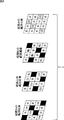
ここで、図2には、レンズ部111の外観が示されている。図2において、レンズ部111の開口部(絞りの部分)には、1次カラーフィルタ112が配置されており、被写体1からの光は、1次カラーフィルタ112を介して、後段のイメージセンサ113に入射されることになる。また、図2において、1次カラーフィルタ112は、その菱形形状が4つの領域に分割されており、各領域はそれぞれ、シアン(Cy)、マゼンタ(Mg)、黄(Ye)、又は白(W)の各色のフィルタからなる。
Here, FIG. 2 shows the appearance of the
図1の説明に戻り、イメージセンサ113は、CMOS(Complementary Metal Oxide Semiconductor)イメージセンサやCCD(Charge Coupled Device)イメージセンサ等の固体撮像装置である。イメージセンサ113は、光電変換素子(フォトダイオード)を有する複数の画素が行列状に2次元配置される画素アレイ部と、画素の駆動やA/D(Analog/Digital)変換などを行う周辺回路部から構成される。
Returning to the description of FIG. 1, the
イメージセンサ113は、レンズ部111からの光を光電変換して、画像信号として画像処理部115に出力する。また、イメージセンサ113の前面には、2次カラーフィルタ114が配置されている。
The
ここで、図3には、2次カラーフィルタ114の外観が示されている。図3において、2次カラーフィルタ114は、赤(R)、緑(G)、青(B)の各色のフィルタからなる。また、2次カラーフィルタ114には、赤外線光を透過させることが可能なIR(Infrared Ray)パスフィルタ(IR)が含まれている。この2次カラーフィルタ114においては、赤(R)、緑(G)、青(B)の各色からなるフィルタと、IRパスフィルタ(IR)がランダムに配列されている。
Here, FIG. 3 shows the appearance of the
すなわち、レンズ開口部に配置される1次カラーフィルタ112と、センサ画素上に配置される2次カラーフィルタ114は、異なる特性を有しており、1次カラーフィルタ112が透過させる色(減法混合の場合における三原色である、シアン(Cy)、マゼンタ(Mg)、黄(Ye))は、2次カラーフィルタ114が透過させる色(加法混合の場合における三原色である、赤(R)、緑(G)、青(B))と、補色の関係にある。
That is, the
なお、以下の説明では、1次カラーフィルタ112における、シアン(Cy)、マゼンタ(Mg)、黄(Ye)、白(W)の各フィルタをそれぞれ、Cyフィルタ、Mgフィルタ、Yeフィルタ、Wフィルタと称する。また、2次カラーフィルタ114における、赤(R)、緑(G)、青(B)の各フィルタをそれぞれ、Rフィルタ、Gフィルタ、Bフィルタと称する。
In the following description, cyan (Cy), magenta (Mg), yellow (Ye), and white (W) filters in the
さらに、以下の説明では、シアン(Cy)、マゼンタ(Mg)、黄(Ye)からなるカラーフィルタを、CMYフィルタとも称する。また、赤(R)、緑(G)、青(B)からなるカラーフィルタを、RGBフィルタとも称する。 Furthermore, in the following description, a color filter composed of cyan (Cy), magenta (Mg), and yellow (Ye) is also referred to as a CMY filter. A color filter composed of red (R), green (G), and blue (B) is also referred to as an RGB filter.
図1の説明に戻り、画像処理部115は、イメージセンサ113から出力される画像信号に対する所定の画像処理を行う。この画像処理としては、例えば、イメージセンサ113から出力される画像信号に対して圧縮センシングを適用して、被写体1の画像(被写体画像)を復元する処理が行われる。なお、圧縮センシングを利用した被写体1の画像(被写体画像)の復元処理の詳細な内容は後述する。
Returning to the description of FIG. 1, the
図1の画像処理装置10は、以上のように構成される。この画像処理装置10においては、その開口部に1次カラーフィルタ112が配置されるレンズ部111により集光された被写体1からの光が、その前面に2次カラーフィルタ114が配置されるイメージセンサ113により光電変換されて、それにより得られる画像信号が、画像処理部115により処理される。
The
<2.入射光量確保の原理> <2. Principle of securing incident light intensity>
次に、図1の画像処理装置10において、イメージセンサ113の受光面が、十分な入射光量を確保する原理について説明する。
Next, the principle that the light receiving surface of the
図4に示すように、図1の画像処理装置10において、イメージセンサ113は、画像信号として、レンズ部111の開口部に配置される1次カラーフィルタ112の各色のフィルタを透過する光の経路に応じた観測画像を出力することになる。
As shown in FIG. 4, in the
ここでは、1次カラーフィルタ112の各色のフィルタを透過する光の経路ごとに、Yeフィルタを透過した光から得られる経路Yeの観測画像、Cyフィルタを透過した光から得られる経路Cyの観測画像、Mgフィルタを透過した光から得られる経路Mgの観測画像、及び、Wフィルタを透過した光から得られる経路Wの観測画像の4つの観測画像が出力されることになる。なお、実際には、画像処理部115においては、これらの4つの観測画像を、重ね合わせて(足し合わせて)得られる画像が観測されることになる。また、以下の説明では、この観測結果を、yとして説明するものとする。
Here, for each path of light that passes through the filters of the respective colors of the
具体的には、1次カラーフィルタ112において、Yeフィルタを透過する経路を通った光が、2次カラーフィルタ114を介してイメージセンサ113により受光されて得られる観測画像(図4の経路Yeの観測画像)は、2次カラーフィルタ114にランダムに配置されたR、Gフィルタを透過した光から得られる赤(R)、緑(G)の画素と、IRパスフィルタを透過した光から得られる黄(Ye)の画素とから構成される。
Specifically, in the
ここで、図5は、減法混合の場合における三原色である、シアン(Cy)、マゼンタ(Mg)、及び、黄(Ye)の各フィルタの特性を示している。一方、図6には、加法混合の場合における三原色である、赤(R)、緑(G)、青(B)の各フィルタの特性を示している。ただし、図5及び図6においては、横軸は各色の波長を示し、縦軸は各色のフィルタを透過する光量を示している。 Here, FIG. 5 shows the characteristics of each filter of cyan (Cy), magenta (Mg), and yellow (Ye), which are the three primary colors in the case of subtractive mixing. On the other hand, FIG. 6 shows the characteristics of each filter of red (R), green (G), and blue (B), which are the three primary colors in the case of additive mixing. In FIGS. 5 and 6, the horizontal axis indicates the wavelength of each color, and the vertical axis indicates the amount of light transmitted through the filter of each color.
これらのフィルタの特性によれば、図5の黄(Ye)の波長域と、図6の赤(R)及び緑(G)の波長域とが対応する関係となっている。したがって、1次カラーフィルタ112のYeフィルタが、赤(R)の成分と、緑(G)の成分を透過するフィルタとしても機能して、2次カラーフィルタ114にランダムに配列されたR、Gフィルタを透過した光から、赤(R)、緑(G)の画素が得られる。一方、1次カラーフィルタ112のYeフィルタは、青(B)の成分を透過するフィルタとしては機能しないので、図中の黒い四角で表すように、青(B)の画素は得られない。
According to the characteristics of these filters, the wavelength range of yellow (Ye) in FIG. 5 and the wavelength range of red (R) and green (G) in FIG. 6 correspond to each other. Therefore, the Ye filter of the
また、これらのフィルタの特性によれば、図5のシアン(Cy)の波長域と、図6の緑(G)及び青(B)の波長域とが対応する関係となっているので、1次カラーフィルタ112のCyフィルタは、緑(G)の成分と、青(B)の成分を透過するフィルタとしても機能することになるが、赤(R)の成分を透過するフィルタとしては機能しないことになる。
Further, according to the characteristics of these filters, the cyan (Cy) wavelength region in FIG. 5 and the green (G) and blue (B) wavelength regions in FIG. The Cy filter of the
このようなCyフィルタの特性から、経路Cyの観測画像(図4)は、2次カラーフィルタ114にランダムに配列されたG、Bフィルタを透過した光から得られる緑(G)、青(B)の画素と、IRパスフィルタを透過した光から得られるシアン(Cy)の画素とから構成される。なお、経路Cyの観測画像(図4)の場合、Cyフィルタが赤(R)の成分を透過させないため、図中の黒い四角で表すように、赤(R)の画素は得られない。 Due to the characteristics of the Cy filter, the observation image (FIG. 4) of the path Cy is green (G), blue (B) obtained from light transmitted through the G and B filters randomly arranged on the secondary color filter 114. ) Pixels and cyan (Cy) pixels obtained from light transmitted through the IR pass filter. Note that in the case of the observation image of the path Cy (FIG. 4), the Cy filter does not transmit the red (R) component, so that the red (R) pixel cannot be obtained as represented by the black square in the drawing.
また、これらのフィルタの特性によれば、図5のマゼンタ(Mg)の波長域と、図6の赤(R)及び青(B)の波長域とが対応する関係となっているので、1次カラーフィルタ112のMgフィルタは、赤(R)の成分と、青(B)の成分を透過するフィルタとしても機能することになるが、緑(G)の成分を透過するフィルタとしては機能しないことになる。
Further, according to the characteristics of these filters, the magenta (Mg) wavelength range in FIG. 5 corresponds to the red (R) and blue (B) wavelength ranges in FIG. The Mg filter of the
このようなMgフィルタの特性から、経路Mgの観測画像(図4)は、2次カラーフィルタ114にランダムに配列されたR、Bフィルタを透過した光から得られる赤(R)、青(B)の画素と、IRパスフィルタを透過した光から得られるマゼンタ(Mg)の画素とから構成される。なお、経路Mgの観測画像(図4)の場合、Mgフィルタが緑(G)の成分を透過させないため、図中の黒い四角で表すように、緑(G)の画素は得られない。 Due to the characteristics of the Mg filter, the observation image of the path Mg (FIG. 4) is red (R), blue (B) obtained from light transmitted through the R and B filters randomly arranged in the secondary color filter 114. ) Pixels and magenta (Mg) pixels obtained from light transmitted through the IR pass filter. In the case of the observation image of the path Mg (FIG. 4), since the Mg filter does not transmit the green (G) component, the green (G) pixel cannot be obtained as represented by the black square in the drawing.
さらに、1次カラーフィルタ112の白(W)のフィルタは、赤(R)、緑(G)、及び、青(B)の全ての成分を透過するフィルタとして機能するので、経路Wの観測画像(図4)は、2次カラーフィルタ114にランダムに配列されたR、G、Bフィルタを透過した光から得られる赤(R)、緑(G)、及び、青(B)の画素と、IRパスフィルタを透過した光から得られる画素とから構成される。
Further, since the white (W) filter of the
このように、レンズ部111の開口部に、減法混合の場合の三原色(シアン(Cy)、マゼンタ(Mg)、黄(Ye))の各色からなる1次カラーフィルタ112を配置し、イメージセンサ113の前面に、加法混合の場合の三原色(赤(R)、緑(G)、青(B))の各色からなる2次カラーフィルタ114を配置する構成を採用することで、図4に示すような、4つの観測画像(観測結果y)が得られることになる。
As described above, the
以上をまとめると、図7の上段に示すように、レンズ部111から、イメージセンサ113の受光面に入射される被写体1からの光は、1次カラーフィルタ112のYeフィルタによって、赤(R)の成分と緑(G)の成分が透過され、さらに、2次カラーフィルタ114のRフィルタにより赤(R)の成分が、Gフィルタにより緑(G)の成分がそれぞれ透過される。これにより、経路Yeの観測画像(図4)として、赤(R)及び緑(G)の画素を含む画像が得られる。
In summary, as shown in the upper part of FIG. 7, the light from the subject 1 incident on the light receiving surface of the
また、図7の中段に示すように、被写体1からの光は、1次カラーフィルタ112のCyフィルタによって、緑(G)の成分と青(B)の成分が透過され、さらに、2次カラーフィルタ114のGフィルタにより緑(G)の成分が、Bフィルタにより青(B)の成分がそれぞれ透過される。これにより、経路Cyの観測画像(図4)として、緑(G)と青(B)の画素を含む画像が得られる。
As shown in the middle part of FIG. 7, the light from the subject 1 is transmitted with the green (G) component and the blue (B) component by the Cy filter of the
また、図7の下段に示すように、被写体1からの光は、1次カラーフィルタ112のMgフィルタによって、赤(R)の成分と青(B)の成分が透過され、さらに、2次カラーフィルタ114のRフィルタにより赤(R)の成分が、Bフィルタにより青(B)の成分がそれぞれ透過される。これにより、経路Mgの観測画像(図4)として、赤(R)及び青(B)の画素を含む画像が得られる。
Further, as shown in the lower part of FIG. 7, the light from the subject 1 is transmitted with the red (R) component and the blue (B) component by the Mg filter of the
なお、ここで、比較のために、レンズ部111の開口部と、イメージセンサ113の前面の両方に、加法混合の場合の三原色(赤(R)、緑(G)、青(B))の各色からなるカラーフィルタが配置される構成を採用した場合に取得される観測画像についてまとめると、図8に示すようになる。
Here, for comparison, the three primary colors (red (R), green (G), and blue (B)) in the case of additive mixing are added to both the opening of the
すなわち、図8の上段に示すように、レンズ部111から、イメージセンサ113の受光面に入射される被写体1からの光は、レンズ部111の開口部に配置された1次カラーフィルタ112のRフィルタによって、赤(R)の成分のみが透過され、さらに、イメージセンサ113の前面に配置された2次カラーフィルタ114のRフィルタにより赤(R)の成分のみが透過される。これにより、経路Rの観測画像として、赤(R)の画素のみを含む画像が得られる。
That is, as shown in the upper part of FIG. 8, the light from the subject 1 incident on the light receiving surface of the
また、図8の中段に示すように、被写体1からの光は、1次カラーフィルタ112のGフィルタによって、緑(G)の成分のみが透過され、さらに、2次カラーフィルタ114のGフィルタにより緑(G)の成分のみが透過される。これにより、経路Gの観測画像として、緑(G)の画素のみを含む画像が得られる。
8, only the green (G) component of the light from the subject 1 is transmitted by the G filter of the
また、図8の下段に示すように、被写体1からの光は、1次カラーフィルタ112のBフィルタにより青(B)の成分のみが透過され、さらに、2次カラーフィルタ114のBフィルタにより青(B)の成分のみが透過される。これにより、経路Bの観測画像として、青(B)の画素のみを含む画像が得られる。
Further, as shown in the lower part of FIG. 8, only blue (B) component of the light from the subject 1 is transmitted by the B filter of the
このように、1次カラーフィルタ112と2次カラーフィルタ114として、共にRGBフィルタを用いてその特性を同一にした場合、各色のフィルタごとに、単一の色成分しか透過されないため、RGBフィルタと補色の関係にあるCMYフィルタを用いてその特性を異ならせた場合と比べて、イメージセンサ113の受光面で受光される光量が減少してしまい、S/N比が悪化することになる。
As described above, when the RGB color filter is used as the
これに対して、図1の画像処理装置10においては、レンズ部111の開口部に配置される1次カラーフィルタ112として、RGBフィルタと補色の関係のあるCMYフィルタを用いる一方、イメージセンサ113の前面に配置される2次カラーフィルタ114としてRGBフィルタを用いることで、1次カラーフィルタと2次カラーフィルタの特性を異ならせている。このような構成を採用した場合、CMYフィルタは、RGBフィルタに対して複数の色成分を透過させることができるので、RGBフィルタのみを用いている場合と比べて、フィルタの組み合わせによる光量のロスを低減して、イメージセンサ113の受光面で受光される光量を確保し、S/N比を改善させることができる。
On the other hand, in the
<3.圧縮センシングを利用した復元処理> <3. Restoration using compressed sensing>
次に、図1の画像処理装置10により実行される、圧縮センシングを利用した復元処理について説明する。
Next, a restoration process using compressed sensing executed by the
上述したように、図1の画像処理装置10においては、画像処理部115によって、イメージセンサ113から出力される画像信号(観測画像)に対して圧縮センシングが適用されることで、被写体1の画像(被写体画像(自然画像))を復元する処理が行われる。
As described above, in the
圧縮センシング(Compressed Sensing, Compressive Sampling)とは、スパース性(零要素が多いという性質)を有する高次元の信号を、少ない観測数から復元する枠組みである。ここでは、復元される高次元の信号が、被写体1の画像(被写体画像)に相当し、観測数が、観測画像を重ね合わせて得られる観測結果yに相当している。 Compressed sensing (Compressed Sensing, Compressive Sampling) is a framework that restores high-dimensional signals with sparsity (the nature of having many zero elements) from a small number of observations. Here, the restored high-dimensional signal corresponds to the image of the subject 1 (subject image), and the number of observations corresponds to the observation result y obtained by superimposing the observation images.
すなわち、図9に示すように、イメージセンサ113から出力される画像信号(図4の4つの観測画像を重ね合わせて得られる画像)を観測結果yとし、被写体1の画像(被写体画像)を原信号xとし、レンズ部111の開口部に配置された1次カラーフィルタ112と、イメージセンサ113の前面に配置された2次カラーフィルタ114を通る過程を観測行列Aとすると、下記の式(1)が成立することになる。
That is, as shown in FIG. 9, the image signal output from the image sensor 113 (image obtained by superimposing the four observation images in FIG. 4) is taken as the observation result y, and the image of the subject 1 (subject image) is the original. Assuming that a process passing through the
![]()
![]()
この式(1)の連立方程式を解くことで、観測結果yと観測行列Aから、原信号xを求めることができる。 The original signal x can be obtained from the observation result y and the observation matrix A by solving the simultaneous equations of Equation (1).
なお、図10に示すように、観測結果yの観測数Mは、N次元の原信号xよりも低次元となるため、一般に解を一意に定めることはできないが、ここでは、N次元の原信号xが、k−スパースであって、非零要素の個数がk個とされることを利用する。つまり、自然画像の特性として、零要素が多いことが知られており、例えば、観測結果yの次元よりも、原信号xの非零要素の数が小さいときに、ランダム性を有する観測行列Aを用いてL1復元法(L1再構成法)を適用することにより、ある確率で、原信号xが復元されることになる。換言すれば、自然画像は、空間周波数方向に対して冗長であるため、サンプリング量を間引いたとしても復元することが可能であるので、ここではそれを利用している。 As shown in FIG. 10, since the observation number M of the observation result y is lower than the N-dimensional original signal x, the solution cannot generally be uniquely determined. It is used that the signal x is k-sparse and the number of non-zero elements is k. That is, it is known that there are many zero elements as the characteristics of the natural image. For example, when the number of non-zero elements of the original signal x is smaller than the dimension of the observation result y, the observation matrix A having randomness By applying the L1 restoration method (L1 reconstruction method) using, the original signal x is restored with a certain probability. In other words, since the natural image is redundant in the spatial frequency direction, it can be restored even if the sampling amount is thinned out.
ここで、Rチャンネルに注目した場合、図11に示すように、レンズ部111の開口部に配置される1次カラーフィルタ112において、Mgフィルタ、Yeフィルタ、及びWフィルタは、赤(R)の成分を透過するが、Cyフィルタは、図中の黒い四角で表すように、赤(R)の成分は透過させないことになる。ここでは、この1次カラーフィルタ112を光が透過する過程をBRと定義する。ただし、このBRは、フォーカス位置に依存することになる。
Here, when attention is paid to the R channel, as shown in FIG. 11, in the
また、図12に示すように、イメージセンサ113の前面に配置される2次カラーフィルタ114において、Rチャンネルに注目した場合には、Rフィルタは、赤(R)の成分を透過するが、図中の黒い四角で表すように、GフィルタとBフィルタは、赤(R)の成分は透過させないことになる。ここでは、この2次カラーフィルタ114を光が透過する過程をCRと定義する。
Further, as shown in FIG. 12, in the
このようにして、BRとCRを定義すれば、1次カラーフィルタ112と2次カラーフィルタ114を通る過程を表す観測行列Aは、BRとCRにより表すことができるので、Rチャンネルにおける被写体画像の復元処理は、下記の式(2)の連立方程式を解くことで実現される。
In this manner, by defining the B R and C R, the observation matrix A representing a process through the
![]()
![]()
なお、図12の2次カラーフィルタ114の配列からも明らかなように、Rチャンネルに注目した場合に、Rフィルタがランダムに配列されているため、サンプリングにランダム性を持たせることが可能となる。また、この復元処理は、局所的な情報を用いるのではなく、画像全体の情報を用いて行われるため、通常のデモザイク処理を行った場合と比べて、モアレを軽減することができる。
As is clear from the arrangement of the
また、ここでは、Rチャンネルに注目した場合を説明したが、Gチャンネル又はBチャンネルに注目した場合も同様に、観測行列Aを、BGとCG又はBBとCBにより表すことができる。 Although the case where the R channel is focused has been described here, the observation matrix A can be similarly expressed by B G and C G or B B and C B when the G channel or the B channel is focused. .
すなわち、Gチャンネルにおける被写体画像の復元処理は、下記の式(3)の連立方程式を解くことで表現される。 That is, the restoration process of the subject image in the G channel is expressed by solving simultaneous equations of the following equation (3).
![]()
![]()
また、Bチャンネルにおける被写体画像の復元処理は、下記の式(4)の連立方程式を解くことで表現される。 The subject image restoration process in the B channel is expressed by solving the simultaneous equations of the following equation (4).
![]()
![]()
以上のように、図1の画像処理装置10は、レンズ部111の開口部に1次カラーフィルタ112を設けたColor-Filtered Apertureの原理を利用した構成を採用しているが、当該1次カラーフィルタ112として、RGBフィルタと補色の関係のあるCMYフィルタを用いる一方、イメージセンサ113の前面に配置される2次カラーフィルタ114としてRGBフィルタを用いることで、1次カラーフィルタと2次カラーフィルタの特性を異ならせている。このようなCMYフィルタとRGBフィルタの組み合わせを用いることで、RGBフィルタのみを用いる場合と比べて、フィルタの組み合わせによる光量のロスを低減することができるため、イメージセンサ113の受光面への十分な入射光量を確保して、S/N比を改善させることができる。
As described above, the
また、画像処理装置10において、イメージセンサ113の前面に配置される2次カラーフィルタ114には、赤(R)、緑(G)、青(B)の各色からなるフィルタと、IRパスフィルタ(IR)がランダムに配列されているため、復元処理により復元される被写体画像におけるモアレを軽減することができる。その結果、画像処理装置10では、イメージセンサ113の受光面への十分な入射光量を確保してS/N比を改善しつつ、モアレを軽減することができる。
In the
なお、上述した説明では、1次カラーフィルタ112と2次カラーフィルタ114の組み合わせとして、CMYフィルタとRGBフィルタの組み合わせを説明したが、カラーフィルタの組み合わせはこれに限らず、例えば、同一の色で波長域を異ならせるなど、特性の異なるカラーフィルタの組み合わせであれば、他の組み合わせを採用するようにしてもよい。
In the above description, the combination of the CMY filter and the RGB filter is described as the combination of the
また、イメージセンサ113の前面に配置される2次カラーフィルタ114には、赤外線光を透過させることが可能なIRパスフィルタが含まれているため、例えば暗い場所等においては、赤外線画像が生成されるようにして、切り替えるようにしてもよい。ただし、2次カラーフィルタ114において、RGBフィルタ以外に、IRパスフィルタを含めるかどうかは任意である。
Further, since the
<4.画像処理の流れ> <4. Flow of image processing>
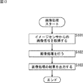
次に、図13のフローチャートを参照して、図1の画像処理装置10により実行される画像処理の流れについて説明する。
Next, the flow of image processing executed by the
ステップS101において、画像処理部115は、イメージセンサ113から出力される画像信号を取得する。
In step S <b> 101, the
ステップS102において、画像処理部115は、イメージセンサ113からの画像信号に対する所定の画像処理を行う。上述したように、この画像処理としては、イメージセンサ113からの画像信号(観測画像)に対して圧縮センシングを適用することで、被写体1の画像(被写体画像)を復元する処理が行われる。
In step S102, the
なお、画像処理としては、被写体画像の復元処理のみならず、例えば、Color-Filtered Apertureの原理を利用して得られる視差情報(色ごとのずれ量)を用いて、奥行き情報などが求められるようにしてもよい。また、奥行き情報は、上述した圧縮センシングを利用して算出されるようにしてもよい。 As image processing, not only subject image restoration processing, but also, for example, depth information or the like is obtained using parallax information (shift amount for each color) obtained using the principle of Color-Filtered Aperture. It may be. Further, the depth information may be calculated using the compressed sensing described above.
ステップS103において、画像処理部115は、ステップS102の画像処理の結果を、後段の回路等に出力する。ステップS103の処理が終了すると、図13の画像処理は終了する。
In step S103, the
以上、図1の画像処理装置10により実行される画像処理について説明した。この画像処理においては、その開口部に1次カラーフィルタ112が配置されるレンズ部111により集光された被写体からの光が、その前面に2次カラーフィルタ114が配置されるイメージセンサ113により光電変換されて、それにより得られる画像信号が、画像処理部115によって、処理されることになる。
The image processing executed by the
<5.撮像装置の構成> <5. Configuration of Imaging Device>
図14は、本技術を適用した撮像装置の一実施の形態を示す図である。 FIG. 14 is a diagram illustrating an embodiment of an imaging apparatus to which the present technology is applied.
図14において、撮像装置300は、レンズ部301、イメージセンサ302、画像処理部303、フレームメモリ304、表示部305、記録部306、操作部307、及び、電源部308から構成される。また、撮像装置300において、画像処理部303、フレームメモリ304、表示部305、記録部306、操作部307、及び、電源部308は、バスライン309を介して相互に接続されている。
In FIG. 14, the
レンズ部301は、上述したレンズ部111(図1)に相当するものである。レンズ部301は、1又は複数のレンズ群等から構成され、被写体からの光(像光)を、イメージセンサ302の受光面上に入射させる。なお、図示はしていないが、レンズ部301の開口部には、4つの領域に分割された各領域がそれぞれ、シアン(Cy)、マゼンタ(Mg)、黄(Ye)、又は白(W)の各色のフィルタからなる1次カラーフィルタ(図1の1次カラーフィルタ112)が配置されている。
The
イメージセンサ302は、例えばCMOSイメージセンサ等からなる上述のイメージセンサ113(図1)に相当するものである。イメージセンサ302は、光電変換素子を有する複数の画素が行列状に2次元配置される画素アレイ部とその周辺回路部とを有する。イメージセンサ302は、レンズ部301によって受光面上に結像された入射光の光量を、画素単位で電気信号に変換して、画像信号として、画像処理部303に出力する。なお、図示はしていないが、イメージセンサ302の前面には、赤(R)、緑(G)、青(B)の各色のフィルタからなる2次カラーフィルタ(図1の2次カラーフィルタ114)が配置されている。
The
画像処理部303は、上述した画像処理部115(図1)に相当するものである。画像処理部303は、イメージセンサ113から出力される画像信号に対する所定の画像処理を行う。この画像処理としては、例えば、イメージセンサ113から出力される画像信号に対して圧縮センシングを適用することで、被写体画像を復元する処理が行われる。
The
また、画像処理部303は、イメージセンサ302から出力される画像信号に対してカメラ信号処理を施す。当該信号処理により得られる画像データは、フレームメモリ304に一時的に格納され、表示部305又は記録部306に供給される。
Further, the
表示部305は、例えば、液晶パネルや有機EL(Electro Luminescence)パネル等から構成され、イメージセンサ302で撮像された動画又は静止画を表示する。記録部306は、イメージセンサ302で撮像された動画又は静止画の画像データを、半導体メモリやビデオテープ等の記録媒体に記録する。
The
操作部307は、ユーザからの操作に従い、撮像装置300が有する各種の機能についての操作指令を発する。電源部308は、画像処理部303、フレームメモリ304、表示部305、記録部306、及び、操作部307の動作に必要となる電力を、これらの供給対象に対して適宜供給する。
The
なお、本技術を適用した撮像装置は、上述した構成に限らず、他の構成であってもよい。例えば、デジタルスチルカメラやデジタルビデオカメラだけでなく、携帯電話機、スマートフォン、タブレット型デバイス、又はパーソナルコンピュータ等の、撮像機能を有する情報処理装置であってもよい。また、本技術を適用した撮像装置は、他の情報処理装置に装着して使用される(又は組み込みデバイスとして搭載される)カメラモジュールであってもよい。 Note that the imaging apparatus to which the present technology is applied is not limited to the configuration described above, and may have another configuration. For example, not only a digital still camera and a digital video camera but also an information processing apparatus having an imaging function, such as a mobile phone, a smartphone, a tablet device, or a personal computer. In addition, the imaging apparatus to which the present technology is applied may be a camera module that is used by being mounted on another information processing apparatus (or mounted as an embedded device).
また、上述した一連の処理(例えば、図13の画像処理)は、ハードウェアにより実行させることもできるし、ソフトウェアにより実行させることもできる。当該一連の処理をソフトウェアにより実行させる場合には、そのソフトウェアを構成するプログラムが、専用のハードウェアに組み込まれているコンピュータ、又は、各種のプログラムをインストールすることで、各種の機能を実行することが可能な、例えば汎用のパーソナルコンピュータ等に、記録媒体からインストールされる。 Further, the above-described series of processing (for example, the image processing of FIG. 13) can be executed by hardware or can be executed by software. When the series of processing is executed by software, a program constituting the software executes various functions by installing a computer incorporated in dedicated hardware or various programs. For example, it is installed from a recording medium in a general-purpose personal computer or the like.
この記録媒体は、コンピュータとは別に、ユーザにプログラムを提供するために配布される、プログラムが記録されている磁気ディスク、光ディスク、光磁気ディスク、若しくは半導体メモリ等よりなるリムーバブルメディアにより構成されるだけでなく、コンピュータに予め組み込まれた状態でユーザに提供される、プログラムが記録されているROMや記録部等で構成される。 This recording medium is composed of a removable medium made of a magnetic disk, an optical disk, a magneto-optical disk, a semiconductor memory, or the like on which the program is recorded, which is distributed to provide the program to the user, separately from the computer. Instead, it is configured by a ROM, a recording unit, and the like that are provided to the user in a state of being pre-installed in the computer and in which a program is recorded.
また、上述した一連の処理を実行させるプログラムは、必要に応じてルータ、モデム等のインターフェースを介して、ローカルエリアネットワーク、インターネット、デジタル衛星放送といった、有線又は無線の通信媒体を介してコンピュータにインストールされるようにしてもよい。 The program for executing the series of processes described above is installed in a computer via a wired or wireless communication medium such as a local area network, the Internet, or digital satellite broadcasting via an interface such as a router or a modem as necessary. You may be made to do.
なお、本技術の実施の形態は、上述した実施の形態に限定されるものではなく、本技術の要旨を逸脱しない範囲において種々の変更が可能である。 The embodiments of the present technology are not limited to the above-described embodiments, and various modifications can be made without departing from the gist of the present technology.
また、本技術は、以下のような構成をとることができる。 Moreover, this technique can take the following structures.
(1)
被写体からの光を集光するレンズ部と、
前記レンズ部の開口部に配置され、所定の特性を有する第1のカラーフィルタと、
前記レンズ部からの光を光電変換して、画像信号として出力するイメージセンサと、
前記イメージセンサの前面に配置され、前記第1のカラーフィルタと異なる特性を有するとともに、各色がランダムに配列された第2のカラーフィルタと、
前記イメージセンサから出力される前記画像信号を処理する画像処理部と
を備える画像処理装置。
(2)
前記第1のカラーフィルタが透過させる色は、前記第2のカラーフィルタが透過させる色と補色の関係にある
(1)に記載の画像処理装置。
(3)
前記第1のカラーフィルタは、シアン(Cy)、マゼンタ(Mg)、黄(Ye)の各色からなるフィルタであり、
前記第2のカラーフィルタは、赤(R)、緑(G)、青(B)の各色からなるフィルタである
(2)に記載の画像処理装置。
(4)
前記第2のカラーフィルタは、赤外線光を透過させることが可能なIR(Infrared Ray)パスフィルタを含んでいる
(3)に記載の画像処理装置。
(5)
前記画像処理部は、前記イメージセンサから出力される画像信号に対して圧縮センシングを適用することで、前記被写体の画像を復元する
(1)乃至(4)のいずれかに記載の画像処理装置。
(6)
前記圧縮センシングにおいては、前記第1のカラーフィルタと前記第2のカラーフィルタを通る過程が観測行列とされ、色チャンネルごとの前記観測行列を用いて、各色チャンネルにおける前記被写体の画像の復元処理が行われる
(5)に記載の画像処理装置。
(7)
画像処理装置の画像処理方法において、
前記画像処理装置が、
その開口部に所定の特性を有する第1のカラーフィルタが配置され、被写体からの光を集光するレンズ部からの光が、その前面に前記第1のカラーフィルタと異なる特性を有するとともに各色がランダムに配列された第2のカラーフィルタが配置されるイメージセンサにより光電変換されることで得られる画像信号を処理する
ステップを含む画像処理方法。
(8)
被写体からの光を集光するレンズ部と、
前記レンズ部の開口部に配置され、所定の特性を有する第1のカラーフィルタと、
前記レンズ部からの光を光電変換して、画像信号として出力するイメージセンサと、
前記イメージセンサの前面に配置され、前記第1のカラーフィルタと異なる特性を有するとともに、各色がランダムに配列された第2のカラーフィルタと、
前記イメージセンサから出力される前記画像信号を処理する画像処理部と
を備える撮像装置。
(1)
A lens unit that collects light from the subject;
A first color filter disposed at an opening of the lens unit and having a predetermined characteristic;
An image sensor that photoelectrically converts light from the lens unit and outputs it as an image signal;
A second color filter disposed on the front surface of the image sensor, having different characteristics from the first color filter and in which each color is randomly arranged;
An image processing apparatus comprising: an image processing unit that processes the image signal output from the image sensor.
(2)
The image processing apparatus according to (1), wherein the color transmitted by the first color filter has a complementary color relationship with the color transmitted by the second color filter.
(3)
The first color filter is a filter composed of each color of cyan (Cy), magenta (Mg), and yellow (Ye),
The image processing apparatus according to (2), wherein the second color filter is a filter including red (R), green (G), and blue (B) colors.
(4)
The image processing apparatus according to (3), wherein the second color filter includes an IR (Infrared Ray) pass filter capable of transmitting infrared light.
(5)
The image processing device according to any one of (1) to (4), wherein the image processing unit restores the image of the subject by applying compression sensing to an image signal output from the image sensor.
(6)
In the compressed sensing, the process passing through the first color filter and the second color filter is an observation matrix, and using the observation matrix for each color channel, restoration processing of the image of the subject in each color channel is performed. The image processing apparatus according to (5).
(7)
In the image processing method of the image processing apparatus,
The image processing apparatus is
A first color filter having a predetermined characteristic is disposed in the opening, and light from the lens unit that collects light from the subject has characteristics different from those of the first color filter on the front surface, and each color is An image processing method including a step of processing an image signal obtained by photoelectric conversion by an image sensor in which second color filters arranged at random are arranged.
(8)
A lens unit that collects light from the subject;
A first color filter disposed at an opening of the lens unit and having a predetermined characteristic;
An image sensor that photoelectrically converts light from the lens unit and outputs it as an image signal;
A second color filter disposed on the front surface of the image sensor, having different characteristics from the first color filter, wherein each color is randomly arranged;
An image processing apparatus comprising: an image processing unit that processes the image signal output from the image sensor.
10 画像処理装置, 111 レンズ部, 112 1次カラーフィルタ, 113 イメージセンサ, 114 2次カラーフィルタ, 115 画像処理部, 300 撮像装置, 301 レンズ部, 302 イメージセンサ, 303 画像処理部
DESCRIPTION OF
Claims (4)
前記レンズ部の開口部に配置され、所定の特性を有する第1のカラーフィルタと、
前記レンズ部からの光を光電変換して、画像信号として出力するイメージセンサと、
前記イメージセンサの前面に配置され、前記第1のカラーフィルタと異なる特性を有するとともに、各色がランダムに配列された第2のカラーフィルタと、
前記イメージセンサから出力される前記画像信号に対して圧縮センシングを適用することで、前記被写体の画像を復元する画像処理部と
を備え、
前記第1のカラーフィルタは、シアン(Cy)、マゼンタ(Mg)、黄(Ye)、白(W)の各色からなるフィルタであり、
前記第2のカラーフィルタは、赤(R)、緑(G)、青(B)の各色と、赤外線光を透過させることが可能なIR(Infrared Ray)パスフィルタからなるフィルタであり、
前記圧縮センシングにおいては、前記第1のカラーフィルタと前記第2のカラーフィルタを通る過程が観測行列とされ、色チャンネルごとの前記観測行列と観測画像を用いて、各色チャンネルにおける前記被写体の画像の復元処理が行われ、
前記観測画像は、
前記シアン(Cy)のフィルタを透過した光が、前記緑(G)、前記青(B)のフィルタと前記IRパスフィルタをさらに透過することで得られる第1の観測画像と、
前記マゼンタ(Mg)のフィルタを透過した光が、前記赤(R)、前記青(B)のフィルタと前記IRパスフィルタをさらに透過することで得られる第2の観測画像と、
前記黄(Ye)のフィルタを透過した光が、前記赤(R)、前記緑(G)のフィルタと前記IRパスフィルタをさらに透過することで得られる第3の観測画像と、
前記白(W)のフィルタを透過した光が、前記赤(R)、前記緑(G)、前記青(B)のフィルタと前記IRパスフィルタをさらに透過することで得られる第4の観測画像と
を含む
画像処理装置。 A lens unit that collects light from the subject;
A first color filter disposed at an opening of the lens unit and having a predetermined characteristic;
An image sensor that photoelectrically converts light from the lens unit and outputs it as an image signal;
A second color filter disposed on the front surface of the image sensor, having different characteristics from the first color filter and in which each color is randomly arranged;
An image processing unit that restores the image of the subject by applying compression sensing to the image signal output from the image sensor;
The first color filter is a filter composed of each color of cyan (Cy), magenta (Mg), yellow (Ye), and white (W),
Said second color filters, red (R), green (G), and Ri filter der consisting colors and, which can transmit infrared light IR (Infrared Ray) pass filters and blue (B),
In the compressed sensing, a process passing through the first color filter and the second color filter is an observation matrix, and using the observation matrix and the observation image for each color channel, the image of the subject in each color channel is detected. Restoration process is performed,
The observed image is
A first observation image obtained by further transmitting the light transmitted through the cyan (Cy) filter through the green (G) and blue (B) filters and the IR path filter;
A second observation image obtained by further transmitting the light transmitted through the magenta (Mg) filter through the red (R) and blue (B) filters and the IR path filter;
A third observation image obtained by further transmitting the light transmitted through the yellow (Ye) filter through the red (R), green (G) filter and the IR path filter;
A fourth observation image obtained by further transmitting the light transmitted through the white (W) filter through the red (R), green (G), and blue (B) filters and the IR path filter. When
An image processing apparatus.
請求項1に記載の画像処理装置。 The image processing apparatus according to claim 1 , wherein the image processing unit calculates depth information using disparity information obtained by performing predetermined image processing on an image signal output from the image sensor.
前記画像処理装置が、
所定の特性を有する第1のカラーフィルタが開口部に配置されるレンズ部であって被写体からの光を集光する前記レンズ部からの光が、前記第1のカラーフィルタと異なる特性を有するとともに各色がランダムに配列された第2のカラーフィルタが前面に配置されるイメージセンサにより光電変換されることで得られる画像信号に対して圧縮センシングを適用することで、前記被写体の画像を復元する
ステップを含み、
前記第1のカラーフィルタは、シアン(Cy)、マゼンタ(Mg)、黄(Ye)、白(W)の各色からなるフィルタであり、
前記第2のカラーフィルタは、赤(R)、緑(G)、青(B)の各色と、赤外線光を透過させることが可能なIRパスフィルタからなるフィルタであり、
前記圧縮センシングにおいては、前記第1のカラーフィルタと前記第2のカラーフィルタを通る過程が観測行列とされ、色チャンネルごとの前記観測行列と観測画像を用いて、各色チャンネルにおける前記被写体の画像の復元処理が行われ、
前記観測画像は、
前記シアン(Cy)のフィルタを透過した光が、前記緑(G)、前記青(B)のフィルタと前記IRパスフィルタをさらに透過することで得られる第1の観測画像と、
前記マゼンタ(Mg)のフィルタを透過した光が、前記赤(R)、前記青(B)のフィルタと前記IRパスフィルタをさらに透過することで得られる第2の観測画像と、
前記黄(Ye)のフィルタを透過した光が、前記赤(R)、前記緑(G)のフィルタと前記IRパスフィルタをさらに透過することで得られる第3の観測画像と、
前記白(W)のフィルタを透過した光が、前記赤(R)、前記緑(G)、前記青(B)のフィルタと前記IRパスフィルタをさらに透過することで得られる第4の観測画像と
を含む
画像処理方法。 In the image processing method of the image processing apparatus,
The image processing apparatus is
The first color filter having a predetermined characteristic is a lens part disposed in the opening, and the light from the lens part that collects light from the subject has a characteristic different from that of the first color filter. A step of restoring the image of the subject by applying compression sensing to an image signal obtained by photoelectric conversion by an image sensor having a second color filter in which each color is randomly arranged arranged in front. Including
The first color filter is a filter composed of each color of cyan (Cy), magenta (Mg), yellow (Ye), and white (W),
Said second color filters, red (R), green (G), and the respective colors of blue (B), Ri filter der which consists of IR-pass filter capable able to transmit infrared light,
In the compressed sensing, a process passing through the first color filter and the second color filter is an observation matrix, and using the observation matrix and the observation image for each color channel, the image of the subject in each color channel is detected. Restoration process is performed,
The observed image is
A first observation image obtained by further transmitting the light transmitted through the cyan (Cy) filter through the green (G) and blue (B) filters and the IR path filter;
A second observation image obtained by further transmitting the light transmitted through the magenta (Mg) filter through the red (R) and blue (B) filters and the IR path filter;
A third observation image obtained by further transmitting the light transmitted through the yellow (Ye) filter through the red (R), green (G) filter and the IR path filter;
A fourth observation image obtained by further transmitting the light transmitted through the white (W) filter through the red (R), green (G), and blue (B) filters and the IR path filter. When
An image processing method including :
前記レンズ部の開口部に配置され、所定の特性を有する第1のカラーフィルタと、
前記レンズ部からの光を光電変換して、画像信号として出力するイメージセンサと、
前記イメージセンサの前面に配置され、前記第1のカラーフィルタと異なる特性を有するとともに、各色がランダムに配列された第2のカラーフィルタと、
前記イメージセンサから出力される前記画像信号に対して圧縮センシングを適用することで、前記被写体の画像を復元する画像処理部と
を備え、
前記第1のカラーフィルタは、シアン(Cy)、マゼンタ(Mg)、黄(Ye)、白(W)の各色からなるフィルタであり、
前記第2のカラーフィルタは、赤(R)、緑(G)、青(B)の各色と、赤外線光を透過させることが可能なIRパスフィルタからなるフィルタであり、
前記圧縮センシングにおいては、前記第1のカラーフィルタと前記第2のカラーフィルタを通る過程が観測行列とされ、色チャンネルごとの前記観測行列と観測画像を用いて、各色チャンネルにおける前記被写体の画像の復元処理が行われ、
前記観測画像は、
前記シアン(Cy)のフィルタを透過した光が、前記緑(G)、前記青(B)のフィルタと前記IRパスフィルタをさらに透過することで得られる第1の観測画像と、
前記マゼンタ(Mg)のフィルタを透過した光が、前記赤(R)、前記青(B)のフィルタと前記IRパスフィルタをさらに透過することで得られる第2の観測画像と、
前記黄(Ye)のフィルタを透過した光が、前記赤(R)、前記緑(G)のフィルタと前記IRパスフィルタをさらに透過することで得られる第3の観測画像と、
前記白(W)のフィルタを透過した光が、前記赤(R)、前記緑(G)、前記青(B)のフィルタと前記IRパスフィルタをさらに透過することで得られる第4の観測画像と
を含む
撮像装置。 A lens unit that collects light from the subject;
A first color filter disposed at an opening of the lens unit and having a predetermined characteristic;
An image sensor that photoelectrically converts light from the lens unit and outputs it as an image signal;
A second color filter disposed on the front surface of the image sensor, having different characteristics from the first color filter and in which each color is randomly arranged;
An image processing unit that restores the image of the subject by applying compression sensing to the image signal output from the image sensor;
The first color filter is a filter composed of each color of cyan (Cy), magenta (Mg), yellow (Ye), and white (W),
Said second color filters, red (R), green (G), and the respective colors of blue (B), Ri filter der which consists of IR-pass filter capable able to transmit infrared light,
In the compressed sensing, a process passing through the first color filter and the second color filter is an observation matrix, and using the observation matrix and the observation image for each color channel, the image of the subject in each color channel is detected. Restoration process is performed,
The observed image is
A first observation image obtained by further transmitting the light transmitted through the cyan (Cy) filter through the green (G) and blue (B) filters and the IR path filter;
A second observation image obtained by further transmitting the light transmitted through the magenta (Mg) filter through the red (R) and blue (B) filters and the IR path filter;
A third observation image obtained by further transmitting the light transmitted through the yellow (Ye) filter through the red (R), green (G) filter and the IR path filter;
A fourth observation image obtained by further transmitting the light transmitted through the white (W) filter through the red (R), green (G), and blue (B) filters and the IR path filter. When
An imaging apparatus including:
Priority Applications (3)
| Application Number | Priority Date | Filing Date | Title |
|---|---|---|---|
| JP2014155662A JP6595161B2 (en) | 2014-07-31 | 2014-07-31 | Image processing apparatus, image processing method, and imaging apparatus |
| US15/328,241 US10593717B2 (en) | 2014-07-31 | 2015-07-21 | Image processing apparatus, image processing method, and imaging apparatus |
| PCT/JP2015/003640 WO2016017107A1 (en) | 2014-07-31 | 2015-07-21 | Image processing apparatus, image processing method, and imaging apparatus |
Applications Claiming Priority (1)
| Application Number | Priority Date | Filing Date | Title |
|---|---|---|---|
| JP2014155662A JP6595161B2 (en) | 2014-07-31 | 2014-07-31 | Image processing apparatus, image processing method, and imaging apparatus |
Publications (3)
| Publication Number | Publication Date |
|---|---|
| JP2016034055A JP2016034055A (en) | 2016-03-10 |
| JP2016034055A5 JP2016034055A5 (en) | 2017-09-07 |
| JP6595161B2 true JP6595161B2 (en) | 2019-10-23 |
Family
ID=53801133
Family Applications (1)
| Application Number | Title | Priority Date | Filing Date |
|---|---|---|---|
| JP2014155662A Active JP6595161B2 (en) | 2014-07-31 | 2014-07-31 | Image processing apparatus, image processing method, and imaging apparatus |
Country Status (3)
| Country | Link |
|---|---|
| US (1) | US10593717B2 (en) |
| JP (1) | JP6595161B2 (en) |
| WO (1) | WO2016017107A1 (en) |
Families Citing this family (3)
| Publication number | Priority date | Publication date | Assignee | Title |
|---|---|---|---|---|
| JP6655790B2 (en) * | 2016-06-16 | 2020-02-26 | パナソニックIpマネジメント株式会社 | Imaging device and imaging system |
| KR102543392B1 (en) | 2017-12-05 | 2023-06-13 | 애어리3디 인크. | Brightfield image processing method for depth acquisition |
| US11721031B2 (en) * | 2020-10-28 | 2023-08-08 | Stmicroelectronics (Research & Development) Limited | Scalable depth sensor |
Family Cites Families (19)
| Publication number | Priority date | Publication date | Assignee | Title |
|---|---|---|---|---|
| JPH03289293A (en) * | 1990-04-04 | 1991-12-19 | Mitsubishi Electric Corp | Image pickup device |
| JP4027441B2 (en) * | 1995-12-18 | 2007-12-26 | オリンパス株式会社 | Color image pickup device |
| US6657663B2 (en) * | 1998-05-06 | 2003-12-02 | Intel Corporation | Pre-subtracting architecture for enabling multiple spectrum image sensing |
| TW448340B (en) * | 2000-12-12 | 2001-08-01 | Ind Tech Res Inst | Single-lens instantaneous three-dimensional image taking apparatus |
| US7426271B2 (en) * | 2003-04-25 | 2008-09-16 | Palo Alto Research Center Incorporated | System and method for establishing secondary channels |
| JP2005354610A (en) * | 2004-06-14 | 2005-12-22 | Canon Inc | Image processing apparatus, image processing method and image processing program |
| SE0402576D0 (en) * | 2004-10-25 | 2004-10-25 | Forskarpatent I Uppsala Ab | Multispectral and hyperspectral imaging |
| JP4949806B2 (en) | 2006-11-10 | 2012-06-13 | オンセミコンダクター・トレーディング・リミテッド | Imaging apparatus and image signal processing apparatus |
| US20090124037A1 (en) * | 2007-11-13 | 2009-05-14 | United Microelectronics Corp. | Method of preventing color striation in fabricating process of image sensor and fabricating process of image sensor |
| JP2009276294A (en) * | 2008-05-16 | 2009-11-26 | Toshiba Corp | Image processing method |
| CN102812709B (en) * | 2009-11-20 | 2015-11-25 | M·辛格 | Compressed color image sampling and the method and system rebuild |
| JP5227368B2 (en) * | 2010-06-02 | 2013-07-03 | パナソニック株式会社 | 3D imaging device |
| JP5507362B2 (en) | 2010-06-30 | 2014-05-28 | パナソニック株式会社 | Three-dimensional imaging device and light transmission plate |
| JP5772446B2 (en) | 2010-09-29 | 2015-09-02 | 株式会社ニコン | Image processing apparatus and image processing program |
| CN103636199B (en) * | 2011-04-07 | 2015-12-23 | 松下电器产业株式会社 | Three-dimensional image pickup device, image processing apparatus, image processing method |
| FR2974449A1 (en) * | 2011-04-22 | 2012-10-26 | Commissariat Energie Atomique | IMAGEUR INTEGRATED CIRCUIT AND STEREOSCOPIC IMAGE CAPTURE DEVICE |
| US8902281B2 (en) * | 2012-06-29 | 2014-12-02 | Alcatel Lucent | System and method for image stabilization in videoconferencing |
| CN102801984B (en) | 2012-07-31 | 2016-04-20 | 陶霖密 | The method of color image sensor and acquisition color digital image |
| US9343491B2 (en) * | 2013-05-06 | 2016-05-17 | Gonzalo Arce | Spectral imaging sensors and methods |
-
2014
- 2014-07-31 JP JP2014155662A patent/JP6595161B2/en active Active
-
2015
- 2015-07-21 WO PCT/JP2015/003640 patent/WO2016017107A1/en active Application Filing
- 2015-07-21 US US15/328,241 patent/US10593717B2/en active Active
Also Published As
| Publication number | Publication date |
|---|---|
| WO2016017107A1 (en) | 2016-02-04 |
| JP2016034055A (en) | 2016-03-10 |
| US20170214890A1 (en) | 2017-07-27 |
| US10593717B2 (en) | 2020-03-17 |
Similar Documents
| Publication | Publication Date | Title |
|---|---|---|
| WO2022088311A1 (en) | Image processing method, camera assembly and mobile terminal | |
| US20110228097A1 (en) | Image Sensor Including Color and Infrared Pixels | |
| US20120154596A1 (en) | Reducing noise in a color image | |
| JP5493054B2 (en) | Image pickup device for picking up three-dimensional moving image and plane moving image, and image pickup apparatus equipped with the image pickup device | |
| WO2017104411A1 (en) | Imaging element, image processing device and method, and program | |
| JP6622481B2 (en) | Imaging apparatus, imaging system, signal processing method for imaging apparatus, and signal processing method | |
| US8111298B2 (en) | Imaging circuit and image pickup device | |
| US9219894B2 (en) | Color imaging element and imaging device | |
| CN210143059U (en) | Image sensor integrated circuit, image sensor, and imaging system | |
| JP4968527B2 (en) | Imaging device | |
| US11275296B2 (en) | Signal processing apparatus and imaging apparatus | |
| US9185375B2 (en) | Color imaging element and imaging device | |
| US20150116554A1 (en) | Color imaging element and imaging device | |
| JP2011176710A (en) | Imaging apparatus | |
| JP2019103129A (en) | Solid state imaging apparatus, method of driving solid state imaging apparatus, and electronic equipment | |
| JP6595161B2 (en) | Image processing apparatus, image processing method, and imaging apparatus | |
| JP2015185943A (en) | Microlens with filter array and solid state image sensor | |
| JPWO2015133130A1 (en) | Video imaging device, signal separation device, and video imaging method | |
| US10075687B2 (en) | Imaging apparatus and imaging method to obtain high quality luminance images | |
| JP2015103971A (en) | Solid-state imaging device and digital camera | |
| JP5108013B2 (en) | Color imaging device, imaging device using the same, and filter | |
| JP2012169705A (en) | Imaging device | |
| US11218679B2 (en) | Image processing device, image processing method, and imaging device | |
| RU2579003C1 (en) | Computer system device for panoramic colour image scanning | |
| JP2008035090A (en) | Signal processing method and camera |
Legal Events
| Date | Code | Title | Description |
|---|---|---|---|
| A711 | Notification of change in applicant |
Free format text: JAPANESE INTERMEDIATE CODE: A712 Effective date: 20160720 |
|
| A521 | Request for written amendment filed |
Free format text: JAPANESE INTERMEDIATE CODE: A523 Effective date: 20170725 |
|
| A621 | Written request for application examination |
Free format text: JAPANESE INTERMEDIATE CODE: A621 Effective date: 20170725 |
|
| A977 | Report on retrieval |
Free format text: JAPANESE INTERMEDIATE CODE: A971007 Effective date: 20180813 |
|
| A131 | Notification of reasons for refusal |
Free format text: JAPANESE INTERMEDIATE CODE: A131 Effective date: 20180828 |
|
| A521 | Request for written amendment filed |
Free format text: JAPANESE INTERMEDIATE CODE: A523 Effective date: 20181022 |
|
| A131 | Notification of reasons for refusal |
Free format text: JAPANESE INTERMEDIATE CODE: A131 Effective date: 20190305 |
|
| A521 | Request for written amendment filed |
Free format text: JAPANESE INTERMEDIATE CODE: A523 Effective date: 20190409 |
|
| TRDD | Decision of grant or rejection written | ||
| A01 | Written decision to grant a patent or to grant a registration (utility model) |
Free format text: JAPANESE INTERMEDIATE CODE: A01 Effective date: 20190829 |
|
| A61 | First payment of annual fees (during grant procedure) |
Free format text: JAPANESE INTERMEDIATE CODE: A61 Effective date: 20190926 |
|
| R150 | Certificate of patent or registration of utility model |
Ref document number: 6595161 Country of ref document: JP Free format text: JAPANESE INTERMEDIATE CODE: R150 |