JP6594174B2 - Image forming apparatus - Google Patents
Image forming apparatus Download PDFInfo
- Publication number
- JP6594174B2 JP6594174B2 JP2015226874A JP2015226874A JP6594174B2 JP 6594174 B2 JP6594174 B2 JP 6594174B2 JP 2015226874 A JP2015226874 A JP 2015226874A JP 2015226874 A JP2015226874 A JP 2015226874A JP 6594174 B2 JP6594174 B2 JP 6594174B2
- Authority
- JP
- Japan
- Prior art keywords
- image forming
- temperature
- forming apparatus
- color misregistration
- color
- Prior art date
- Legal status (The legal status is an assumption and is not a legal conclusion. Google has not performed a legal analysis and makes no representation as to the accuracy of the status listed.)
- Expired - Fee Related
Links
Images


Landscapes
- Facsimile Scanning Arrangements (AREA)
- Laser Beam Printer (AREA)
- Exposure Or Original Feeding In Electrophotography (AREA)
- Electrophotography Configuration And Component (AREA)
- Control Or Security For Electrophotography (AREA)
- Color Electrophotography (AREA)
Description
本発明は、光走査装置を備える画像形成装置に関する。 The present invention relates to an image forming apparatus including an optical scanning device.
電子写真方式を用いた画像形成装置は、光走査装置から出射される光ビームで感光体を露光することにより、感光体上に潜像を形成し、形成された潜像をトナーによって現像することでトナー像として顕像化する。感光体上に形成されたトナー像は記録材、又は中間転写体上に転写され、定着器の熱や圧力により記録材に定着され、画像形成が完了した記録材が装置外に排出される。光走査装置は、光源、光源から出射された光ビームを偏向するために回転駆動される回転多面鏡、回転多面鏡によって偏向された光ビームを感光体に導くレンズやミラー等が光学箱(筐体)に収容、保持された構成となっている。 An image forming apparatus using an electrophotographic system forms a latent image on a photosensitive member by exposing the photosensitive member with a light beam emitted from an optical scanning device, and develops the formed latent image with toner. To visualize the toner image. The toner image formed on the photosensitive member is transferred onto a recording material or an intermediate transfer member, fixed on the recording material by heat or pressure of a fixing device, and the recording material on which image formation has been completed is discharged out of the apparatus. The optical scanning device includes a light source, a rotating polygon mirror that is rotationally driven to deflect the light beam emitted from the light source, and a lens and a mirror that guide the light beam deflected by the rotating polygon mirror to a photoconductor. Body).
現在、カラー複写機では、各色それぞれに対応する光走査装置を配置するのでなく、1つの光走査装置によって複数色の感光体を露光する方式が主流となりつつある。この方式では、画像形成装置内の温度が変化すると光走査装置の光学箱等が熱膨張するおそれがある。加えて、光学箱内に発生する熱分布の影響により、光学箱の材質に含有されるガラスフィラー等の異方性により、光学箱内は複雑な熱膨張変形を起こすおそれがある。このため、レンズやミラーの位置が変化し、各色の感光体へ導かれる光ビームの位置がそれぞれ変化するおそれがある。この状態で画像形成を行うと、色ずれが発生するおそれがある。このため、光走査装置内及び光走査装置周囲の複数個所に温度検知手段を設け、両者の温度を参照して、色ずれ量を補正する手法が提案されている(例えば、特許文献1参照)。このような構成では、色ずれの主要因である光走査装置内と、画像形成装置内の2カ所に温度検知手段が設けられている。これにより、回転多面鏡を回転させるスキャナモータの自己昇温だけでなく、画像形成装置の他の発熱源の温度上昇や、画像形成装置の設置環境の温度変動を検知することができる。その結果、画像形成装置の稼動状況に依らず、高精度な色ずれ補正を行っている。 At present, in color copying machines, instead of arranging optical scanning devices corresponding to the respective colors, a method of exposing a plurality of color photoreceptors by one optical scanning device is becoming mainstream. In this method, when the temperature in the image forming apparatus changes, the optical box of the optical scanning apparatus may thermally expand. In addition, due to the influence of the heat distribution generated in the optical box, there is a possibility that complicated thermal expansion deformation may occur in the optical box due to anisotropy of a glass filler or the like contained in the material of the optical box. For this reason, the position of the lens or mirror may change, and the position of the light beam guided to the photoreceptor of each color may change. If image formation is performed in this state, color misregistration may occur. For this reason, a method has been proposed in which temperature detection means is provided at a plurality of locations in the optical scanning device and around the optical scanning device, and the color misregistration amount is corrected by referring to the temperatures of both (see, for example, Patent Document 1). . In such a configuration, temperature detection means are provided in two places in the optical scanning apparatus and the image forming apparatus which are main causes of color misregistration. Accordingly, it is possible to detect not only the self-temperature increase of the scanner motor that rotates the rotary polygon mirror but also the temperature rise of other heat sources of the image forming apparatus and the temperature fluctuation of the installation environment of the image forming apparatus. As a result, highly accurate color misregistration correction is performed regardless of the operating status of the image forming apparatus.
しかし、光走査装置内や画像形成装置内に複数の温度検知手段を設けることで、コストアップするおそれがある。このため、光走査装置内及び画像形成装置の雰囲気の両者の温度変動を的確に検知し、かつ色ずれと相関のある箇所に温度検知手段を配置し、温度検知手段が一つでも精度の高い色ずれ補正を可能とする構成が求められている。 However, the provision of a plurality of temperature detection means in the optical scanning device or the image forming apparatus may increase the cost. For this reason, temperature fluctuations in both the optical scanning device and the atmosphere of the image forming apparatus are accurately detected, and the temperature detection means is disposed at a location correlated with the color misregistration, so that even one temperature detection means has high accuracy. There is a need for a configuration that enables color misregistration correction.
また、画像形成装置には、感光体周辺に結露ヒータを設ける構成があり、画像形成装置が停止状態にあるときも感光体の温度を低下させない方法を採用することがある。感光体の周辺に備えられる光走査装置は、結露ヒータの位置によっては局所的な煽り熱を受けるため、スキャナモータの自己昇温や画像形成装置内の雰囲気温度の変動とは異なる色ずれを示すことがある。したがって、一つの温度検知手段を設ける構成では、これらすべての温度変動を一つの温度検知手段により検知することが求められる。 In addition, the image forming apparatus has a configuration in which a dew condensation heater is provided around the photoconductor, and a method that does not lower the temperature of the photoconductor even when the image forming apparatus is in a stopped state may be employed. Since the optical scanning device provided around the photosensitive member is subjected to local scorching heat depending on the position of the dew condensation heater, it exhibits a color shift different from the self-temperature rise of the scanner motor and the fluctuation of the ambient temperature in the image forming apparatus. Sometimes. Therefore, in a configuration in which one temperature detecting means is provided, it is required to detect all these temperature fluctuations by one temperature detecting means.
本発明は、このような状況のもとでなされたもので、一つの温度検知手段によって、光走査装置、画像形成装置の雰囲気、結露ヒータ等の温度変動を検知することを目的とする。 The present invention has been made under such circumstances, and an object thereof is to detect temperature fluctuations of an optical scanning device, an atmosphere of an image forming apparatus, a dew condensation heater, and the like by a single temperature detection unit.
上述した課題を解決するために、本発明は、以下の構成を備える。 In order to solve the above-described problems, the present invention has the following configuration.
(1)それぞれ異なる色のトナー像を担持する複数の感光体と、前記複数の感光体を露光するための光ビームを出射する複数の光源と、前記複数の光源から出射された複数の光ビームがそれぞれ対応する感光体を走査するように前記複数の光ビームを偏向する回転多面鏡と、前記回転多面鏡を回転させるモータと、前記モータが取り付けられた基板と、を有する偏向手段と、前記偏向手段によって偏向された前記複数の光ビームをそれぞれ対応する感光体に導く光学部材と、前記偏向手段及び前記光学部材が設置される設置面と、前記設置面から立設し前記偏向手段及び前記光学部材を取り囲む第一の側壁と、前記第一の側壁を取り囲む第二の側壁と、を有する筐体と、前記光ビームの走査方向において前記筐体に隣接して配置された熱源と、前記第一の側壁と前記第二の側壁の間に設けられた温度検知手段と、前記複数の感光体上のトナー像を記録紙に転写するための転写手段と、前記温度検知手段の検知結果に基づいて前記複数の感光体から記録紙上に転写されるトナー像間の色ずれを補正する制御手段と、を備え、前記温度検知手段は、前記第二の側壁のうちの前記熱源と対向する部分と、前記第一の側壁のうち前記第二の側壁のうちの前記熱源と対向する部分と対向する部分と、の間に配置されていることを特徴とする画像形成装置。 (1) A plurality of photoconductors that carry toner images of different colors, a plurality of light sources that emit light beams for exposing the plurality of photoconductors, and a plurality of light beams emitted from the plurality of light sources. Each of the rotating polygon mirror for deflecting the plurality of light beams so as to scan the corresponding photosensitive member, a motor for rotating the rotating polygon mirror, and a substrate on which the motor is attached, An optical member that guides the plurality of light beams deflected by the deflecting means to the corresponding photosensitive members, an installation surface on which the deflecting means and the optical member are installed, an erected from the installation surface, and the deflecting means and the a first side wall surrounding the optical member, and the front Stories second sidewall surrounding the first sidewall, a housing having a heat source disposed adjacent to the housing in the scanning direction of the light beam And transfer means for transferring a temperature detecting means provided between said second side wall and said first side wall, a toner image on the plurality of photosensitive member to the recording paper, the detection result of said temperature detecting means And a control unit that corrects color misregistration between toner images transferred from the plurality of photosensitive members onto the recording paper, and the temperature detection unit faces the heat source in the second side wall. part and an image forming apparatus, wherein said heat source and a portion facing a portion facing, that you have arranged between one of said second side wall of said first side wall.
本発明によれば、一つの温度検知手段によって、光走査装置、画像形成装置の雰囲気、結露ヒータ等の温度変動を検知することができる。 According to the present invention, it is possible to detect temperature fluctuations in the optical scanning device, the atmosphere of the image forming apparatus, the dew condensation heater, and the like by a single temperature detection unit.
以下、図面に沿って本発明の実施例を説明する。なお、以下の説明において、後述する回転多面鏡の回転軸方向をZ軸方向、光ビームの走査方向である主走査方向又は反射ミラーの長手方向をY軸方向、Y軸及びZ軸に垂直な方向をX軸方向とする。 Embodiments of the present invention will be described below with reference to the drawings. In the following description, the rotation axis direction of the rotary polygon mirror described later is the Z-axis direction, the main scanning direction that is the scanning direction of the light beam, or the longitudinal direction of the reflection mirror is the Y-axis direction, perpendicular to the Y-axis and the Z-axis. Let the direction be the X-axis direction.
[画像形成装置の構成]
図1は、実施例の電子写真方式の画像形成装置100の概略断面図である。図1に示す画像形成装置100は、イエロー(Y)、マゼンタ(M)、シアン(C)、ブラック(Bk)の各色のトナー像を形成する4基の画像形成部101Y、101M、101C、101Bkを備える。以降、各色を表す符号Y、M、C、Bkは、必要な場合を除き省略する。画像形成部101は、それぞれ感光体である感光ドラム102を備える。感光ドラム102は、水平方向(X軸方向)において異なる位置に配置されている。また、各画像形成部101は、感光ドラム102を帯電する帯電装置103、感光ドラム102上(感光体上)の静電潜像をトナーにより現像する現像装置104を備える。更に、各画像形成部101は、感光ドラム102上の残留したトナーを感光ドラム102上から除去するクリーニング装置111を備える。
[Configuration of Image Forming Apparatus]
FIG. 1 is a schematic sectional view of an electrophotographic
画像形成装置100の本体には、転写ローラ105Y、105M、105C、105Bk、中間転写ベルト106、クリーニング装置112、排紙部110、転写ローラ107、定着装置108が備えられている。画像形成装置100には、記録材が収容される収容部109、光走査装置200が備えられ、光走査装置200は、Z方向において画像形成部101と収容部109との間に配置されている。光走査装置200は、各感光ドラム102に対して重力方向下側(−Z軸方向)に配置されている。なお、光走査装置200は、重力方向上側(+Z軸方向)から感光ドラム102を露光するように配置されてもよい。中間転写ベルト106は、図中、矢印方向(反時計回り方向)に回転する。
The main body of the
次に、画像形成プロセスについて説明する。光走査装置200は、帯電装置103Y、103Mによってそれぞれ帯電された第一の感光体である感光ドラム102Y、102Mを露光する光ビームLY、LMを出射する。光走査装置200は、帯電装置103C、103Bkによってそれぞれ帯電された第二の感光体である感光ドラム102C、102Bkを露光する光ビームLC、LBkを出射する。光ビームが照射される(露光される)ことで感光ドラム102Y、102M、102C、102Bk上には静電潜像が形成される。
Next, the image forming process will be described. The
現像装置104Yは、感光ドラム102Y上に形成された静電潜像をイエローのトナーによって現像する。現像装置104Mは、感光ドラム102M上に形成された静電潜像をマゼンタのトナーによって現像する。現像装置104Cは、感光ドラム102C上に形成された静電潜像をシアンのトナーによって現像する。現像装置104Bkは、感光ドラム102Bk上に形成された静電潜像をブラックのトナーによって現像する。
The developing
感光ドラム102Y上に形成されたイエローのトナー像は、転写部Tyにおいて転写ローラ105Yによって中間転写体である中間転写ベルト106に転写される。クリーニング装置111Yは、感光ドラム102Yの回転方向の転写部Tyと帯電装置103Yの帯電部との間において、中間転写ベルト106に転写されずに感光ドラム102Y上に残留したトナーを回収する。感光ドラム102M上に形成されたマゼンタのトナー像は、転写部Tmにおいて転写ローラ105Mによって中間転写ベルト106に転写される。クリーニング装置111Mは、感光ドラム102Mの回転方向の転写部Tmと帯電装置103Mの帯電部との間において、中間転写ベルト106に転写されずに感光ドラム102M上に残留したトナーを回収する。
The yellow toner image formed on the
感光ドラム102C上に形成されたシアンのトナー像は、転写部Tcにおいて転写ローラ105Cによって中間転写ベルト106に転写される。クリーニング装置111Cは、感光ドラム102Cの回転方向の転写部Tcと帯電装置103Cの帯電部との間において、中間転写ベルト106に転写されずに感光ドラム102C上に残留したトナーを回収する。感光ドラム102Bk上に形成されたブラックのトナー像は、転写部TBkにおいて転写ローラ105Bkによって中間転写ベルト106に転写される。クリーニング装置111Bkは、感光ドラム102Bkの回転方向の転写部TBkと帯電装置103Bkの帯電部との間において、中間転写ベルト106に転写されずに感光ドラム102Bk上に残留したトナーを回収する。本実施例のクリーニング装置111は、感光ドラム102に当接するブレードを備え、このブレードによって感光ドラム上に残留したトナーを掻き取ることによって、残留トナーを回収する。画像形成部101が各色成分に対応するトナー像を中間転写ベルト106上に順次重ねて転写することで、中間転写ベルト106上にはフルカラーのトナー像が形成される。
The cyan toner image formed on the
中間転写ベルト106上に転写されたトナー像は、中間転写ベルト106の矢印方向への回転に伴い、転写部Tsへと搬送される。このとき、収容部109内の記録紙が給紙ローラ120により1枚ずつ給紙され、搬送ローラ121により転写部Tsへと搬送される。給紙ローラ120によって搬送される記録紙は、搬送ローラ121によって記録紙の位置と転写部Tsへの送り出しのタイミングが調整され、中間転写ベルト106上のトナー像と接触するように転写部Tsに供給される。即ち、給紙ローラ120及び搬送ローラ121は、収容部109から排紙部110に向けて記録紙を搬送する搬送手段として機能する。更に、記録紙が収容部109から排紙部110に搬送される経路が搬送経路に相当する。
The toner image transferred onto the
中間転写ベルト106上に転写されたトナー像と、搬送ローラ121から搬送された記録紙が転写部Tsに搬送されると、転写ローラ107に転写電圧が印加され、中間転写ベルト106上のトナー像が記録紙に転写される。転写部Tsにおいてトナー像が転写された記録紙は、定着装置108へと搬送される。定着装置108は、記録紙を搬送しながら、記録材を加熱することによって、トナー像を記録紙に定着させる。その後、トナー像を定着した記録材は排紙部110に排紙される。即ち、画像形成部101Y、101M、101C、101Bkと中間転写ベルト106と転写ローラ107は、Z軸方向において収容部109と排紙部110との間に配置される画像形成手段として機能する。光走査装置200、画像形成部101、中間転写ベルト106、転写ローラ107及び定着装置108は、協働して画像形成を行う。
When the toner image transferred onto the
画像形成装置100は、中間転写ベルト106の回転方向に関し、転写部Tsと転写部Tyとの間に、クリーニング装置112を備える。クリーニング装置112は、中間転写ベルト106に当接するブレードを備え、ブレードによって中間転写ベルト106上に残留したトナーを掻き取る。これにより、クリーニング装置112は、転写部Tsにおいて記録紙に転写されずに中間転写ベルト106上に残留したトナーを清掃する。
The
[光走査装置]
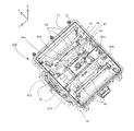
図2は本実施例の光走査装置200を示す概略斜視図である。光走査装置200の内部及び外周部には、レーザ光を出射する光源が搭載された光源ユニット61、レーザ光を反射、偏向する回転多面鏡41、回転多面鏡41を駆動させるスキャナモータ42が設置されている。回転多面鏡41及びスキャナモータ42は、基板45に取り付けられており、回転多面鏡41、スキャナモータ42及び基板45は、偏向手段である偏向器として機能する。また、光走査装置200の内部には、レーザ光を被走査面上へ案内し、結像するために必要な光学レンズ60(60a、60b)、反射ミラー62が設置されている。これらは、筐体である光学箱90に設置されている。
[Optical scanning device]
FIG. 2 is a schematic perspective view showing the
回転多面鏡41により偏向走査された光は、主走査方向に強くパワーを有する第一のレンズ60aを通過した後、副走査方向に強くパワーを有する第二のレンズ60bに案内されるよう構成されている。その後、反射ミラー62により少なくとも1回反射された光は、被走査面である感光ドラム102へと案内されて結像される。第一のレンズ60a、第二のレンズ60b及び反射ミラー62は、光学部材を構成する。第一のレンズ60aは、回転多面鏡41によって偏向されたレーザ光LY、LM、LC、LBkを感光ドラム102Y、102M、102C、102Bkに導くレンズ及び反射ミラーのうち、レーザ光LY、LM、LC、LBkが最初に入射するレンズである。
The light deflected and scanned by the
光学箱90は、偏向器及び光学部材が設置される設置面と、設置面から立設し偏向器及び光学部材を取り囲む第一の側壁である内壁72と、内壁72を取り囲む第二の側壁である外壁71とを有する。光学箱90を構成する側壁は、スキャナモータ42又は画像形成装置100の様々な駆動源から発生する振動に対して強くするために、外壁71と内壁72の二重壁構造になっている。スキャナモータ42を駆動させるモータ束線43は外壁71と内壁72の間を通してレーザ光の発光を制御するレーザ基板872に連結されており、スキャナモータ42の駆動も併せて制御している。
The
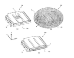
図3は図2で示した光走査装置200にカバー201を装着した図である。カバー201には4つのガラス窓202が備えられており、それぞれからY、M、C、Bkの感光ドラム102に対応するレーザ光LY、LM、LC、LBk(図1参照)が出射される。光走査装置200は、カバー201を装着した状態で画像形成装置100に設置される。
FIG. 3 is a view in which a
また、図3では熱源である結露ヒータ500の位置も併せて示す。結露ヒータ500は、回転多面鏡41に対して光源が設けられた側とは反対側に取り付けられる。画像形成装置100では、例えばユーザが低温環境から暖房等によって部屋の温度を上昇させたときに、感光ドラム102が結露して画像不良が発生する場合がある。その対策として、感光ドラム102周辺に結露ヒータ500を設け、画像形成装置100が画像形成を行っていないような停止状態にあるときも感光ドラム102の温度を低下させないようにしている。結露ヒータ500は、不図示の結露ヒータホルダによって画像形成装置100内に取り付けられ、光走査装置200の側面(外壁71)から隙間を空けた位置、言い換えれば所定の距離をおいて配置される。この位置に配置することで、感光ドラム102の結露を防止する効果を奏すると共に、画像形成装置100を大型化することなく結露ヒータ500の設置を可能とする。結露ヒータ500は上述したように、画像形成動作を行っていないような画像形成装置100の温度が低いときに感光ドラム102を温め、感光ドラム102の結露を防止する。このため、画像形成装置100が停止しているときに結露ヒータ500はオンされ、画像形成装置100が稼働しており画像形成装置100内の温度が昇温する際には、結露ヒータ500は不要となるため、結露ヒータ500はオフされる。これにより、結露ヒータ500による保温が不要な場合には、省電力を実現できる。
FIG. 3 also shows the position of the
[温度センサの位置]
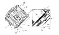
図4は本実施例の温度センサを示した図である。なお、見易さのため、図2で説明した符号の一部を省略している。図4(a)は光走査装置200のカバー201を外した状態を示し、図4(b)は図4(a)の四角い枠線で囲った部分を拡大した図である。本実施例の温度センサ300は、次の3つの条件を満たす位置に設けられている。
〔1〕光学箱90の外壁71と内壁72の間
〔2〕結露ヒータ500が設置された側面側
〔3〕回転多面鏡41からの距離Lが最も近い位置
〔1〕の条件は、画像形成装置100内の雰囲気温度の温度変動を検知することを目的としている。〔2〕の条件は、結露ヒータ500の温度変動を検知することを目的としている。〔3〕の、結露ヒータ500が設けられた側の位置の中で、回転多面鏡41からの距離が最も短くなる位置という条件は、光走査装置200内の温度変動を検知することを目的としている。なお、温度センサ300は、光学箱90の外壁71と内壁72の間の、結露ヒータ500が設置された側面側で、2つの第一のレンズ60aの長手方向の延長線で囲まれる範囲内に設置されてもよい。
[Temperature sensor position]
FIG. 4 is a view showing the temperature sensor of this embodiment. For ease of viewing, some of the reference numerals described in FIG. 2 are omitted. 4A shows a state in which the
[1] Between the
温度センサ300には束線310が連結されており、束線310がばらけることがないように、不図示の結束バンドによって、モータ束線43と共にまとめられている。また、外壁71には、温度センサ300が画像形成装置100の雰囲気温度及び結露ヒータ500の温度を正しく検知できるよう、外壁71を貫通する穴である貫通穴210が備えられている。図5は、外壁71に設けられた貫通穴210を示す図である。本実施例では、貫通穴210は、角丸の矩形となっているが、温度センサ300が画像形成装置100の雰囲気温度及び結露ヒータ500の温度を正しく検知できるような形状であれば、他の形状の貫通穴であってもよい。このように、本実施例では、光走査装置200の二重壁である外壁71及び内壁72の間に温度センサ300を設け、外壁71に貫通穴210を備える構成である。これにより、温度センサ300が、画像形成装置100内の雰囲気温度及び結露ヒータ500の温度変動を測定できるようにしている。
A bundled
[色ずれと温度変化量の相関性]
図6は本実施例において想定している光走査装置200の温度変動の要因となる3つの昇温パターンを示す図である。図6(a)は、温度変動のうち、光走査装置200のスキャナモータ42による自己昇温を示しており、昇温部は光走査装置200の中央に設けられたスキャナモータ42による領域Aとなる。図6(b)は、温度変動のうち、画像形成装置100内の雰囲気温度が変化した様子を示しており、光走査装置200全体が昇温する場合を示し、昇温部は光走査装置200全体の領域Bとなる。図6(c)は、温度変動のうち、結露ヒータ500による昇温を示しており、結露ヒータ500が設けられた光走査装置200の側面が局所的に昇温し、昇温部は領域Cとなる。なお、図6(a)のように領域Aが昇温する状態をモードA、図6(b)のように領域Bが昇温する状態をモードB、図6(c)のように領域Cが昇温する状態をモードCという。
[Correlation between color shift and temperature change]
FIG. 6 is a diagram showing three temperature rising patterns that cause the temperature fluctuation of the
図7は、図6(a)のモードAから図6(c)のモードCにおける、外壁71と内壁72の間(以下、二重壁内ともいう)に設置された温度センサ300により検知した昇温量と色ずれ量(変動量)を示した図である。いずれも横軸は温度変動[℃]を示し、縦軸は色ずれ量[μm]を示す。比較のため、光走査装置200内の回転多面鏡41近傍に温度センサを設置した場合に検知した昇温量(温度変動)と色ずれ量も併せて示す。
FIG. 7 is detected by the
図7(a)では、画像形成装置100の電源をオフにして十分に時間が経過した状態から、印刷動作を連続して行った場合の昇温量と色ずれの変動を示した結果である。ややばらつきはあるものの、回転多面鏡41の近傍及び二重壁内のどちらにおいても、温度が上昇するにつれて色ずれ量が線形に変動していることがわかる。図7(a)では、二重壁内及び回転多面鏡41のいずれで検知した場合でも、温度変動が大きくなるほど色ずれ量も大きくなっている。また、実際の昇温量で見てみると、回転多面鏡近傍では4.5℃程度昇温しているのに対し、二重壁内での昇温量は3℃弱程度である。このことから、モードAの温度変動に対しては、回転多面鏡41近傍の方がより温度変動を捉えていることがわかる。
FIG. 7A shows the results of the temperature rise and the color misregistration when the printing operation is continuously performed from a state where a sufficient time has elapsed after the power of the
図7(b)では、画像形成装置100を設置した環境温度(雰囲気温度)を15℃変動させたときの色ずれ量と回転多面鏡41近傍及び二重壁内の温度変動を示したものである。図7(a)と同様に、両者共に昇温量と色ずれ量には線形相関があることがわかる。図7(b)では、二重壁内及び回転多面鏡41のいずれで検知した場合でも、温度変動が大きくなるほど色ずれ量も大きくなっている。温度変動を見てみると、回転多面鏡41近傍よりも、二重壁内の方が昇温しており、画像形成装置100の雰囲気温度が変化する場合には、二重壁内の方が温度変動を捉えていることがわかる。
FIG. 7B shows the color shift amount and the temperature fluctuation in the vicinity of the
図7(c)は、画像形成装置100の電源がオフされた状態で結露ヒータ500をオンし、十分に時間が経過してから、印刷を連続で行った際の昇温量と色ずれ量を示した図である。画像形成装置100の電源がオンされると共に結露ヒータ500はオフされる。そのため、光走査装置200は結露ヒータ500がオフした影響を受けて温度が低下していき、画像形成装置100が十分に稼働するとその温度は一定になる。図7(c)に示す結果は、その温度低下域での状態を示している。回転多面鏡41近傍の温度と色ずれ量の関係を見ると、回転多面鏡41近傍では温度が略変化していないにも関わらず、色ずれ量が変動していることがわかる。即ち、回転多面鏡41近傍では、結露ヒータ500に起因する温度変動を捉えていないことがわかる。
FIG. 7C shows the amount of temperature rise and color misregistration when the
光走査装置200は、図6(a)に示したように、回転多面鏡41の回転と共に光走査装置200の中央(領域A)から昇温していく。一方で、結露ヒータ500によって全体的に昇温していた光走査装置200が、結露ヒータ500がオフされたことによって、全体的に冷却していく。このため、スキャナモータ42の昇温が光学箱90全体に伝わって色ずれが発生するよりも前に、光学箱90が冷却してしまう。そのため、回転多面鏡41近傍は、結露ヒータ500がオフされたことによる冷却と同等の昇温をするものの、色ずれ量はスキャナモータ42の昇温よりも結露ヒータ500がオフされたことの影響を受けて変動してしまう。
As shown in FIG. 6A, the temperature of the
一方で、二重壁内の温度センサ300により検知された温度は、図7(a)で示したようにスキャナモータ42の昇温の影響が少ないため、結露ヒータ500がオフされたことによる影響の方が支配的になる。これにより、図7(c)の矢印で示すように、結露ヒータ500がオフされた影響を受け温度が低下するため、色ずれ量との相関が高くなっている。
On the other hand, the temperature detected by the
以上のことから、回転多面鏡41近傍で温度変動を検知した場合は、モードA及びモードBの温度変動に対しては高い相関を示すが、モードCの温度変動に対しては相関が低くなる。一方、本実施例の二重壁内で温度変動を検知した場合には、モードA及びモードBの温度変動に対して高い相関を示すだけでなく、モードCの温度変動に対しても高い相関を示すことがわかる。
From the above, when temperature fluctuation is detected in the vicinity of the
[色ずれ補正効果]
図8は、図7で示した色ずれ量と温度変動の関係に加え、温度変動による色ずれ補正を実施した後の色ずれ補正残差を示した図である。図8(a)から図8(c)は、図7(a)から図7(c)に対応している。また、図8の左側は、回転多面鏡41近傍で温度変動を検知した場合に、その検知結果に基づき色ずれ補正を実施した場合を示す。図8の右側は、本実施例の二重壁内で温度変動を検知した場合に、その検知結果に基づき色ずれ補正を実施した場合を示す。
[Color shift correction effect]
FIG. 8 is a diagram showing a color misregistration correction residual after performing color misregistration correction due to temperature variation in addition to the relationship between the color misregistration amount and temperature variation shown in FIG. FIGS. 8A to 8C correspond to FIGS. 7A to 7C. Further, the left side of FIG. 8 shows a case where color shift correction is performed based on the detection result when a temperature variation is detected in the vicinity of the
まず、左上の図8(a)「回転多面鏡近傍」のグラフについて説明する。図7(a)のモードAの昇温に対して、回転多面鏡41近傍の温度変動と色ずれ量を再掲したものが「補正前」のグラフである。回転多面鏡41近傍の「補正前」のグラフを線形近似すると、「補正前」のグラフは、「y=14x」で近似することができる。ここで、「y=14x」は、温度変動1℃あたり14μmの色ずれが発生することを意味し、以下の線形近似も同様である。また、図7(b)のモードBの昇温に対して、回転多面鏡41近傍の温度変動と色ずれ量を再掲したものが図8(b)「回転多面鏡近傍」の「補正前」のグラフであり、「y=32x」で近似することができる。更に、図7(c)のモードCの昇温に対して、回転多面鏡41近傍の温度変動と色ずれ量を再掲したものが図8(c)「回転多面鏡近傍」の「補正前」のグラフであり、「y=−83x」で近似することができる。これらの「補正前」のグラフを、ある一つの式により近似し、温度変動に応じて色ずれ量を線形補正した後の色ずれ量が、「補正後」の各グラフである。即ち、回転多面鏡41近傍で検知した温度変動に基づき色ずれ量を補正した後の最終的な色ずれ量が、「補正後」のグラフに相当する。
First, the graph of FIG. 8A “near rotating polygon mirror” in the upper left will be described. The graph “before correction” shows the temperature fluctuation and color misregistration amount in the vicinity of the
このようにして色ずれ量を補正した場合、図8(a)「回転多面鏡近傍」では、補正後の色ずれ量が概ね±10μmの範囲内に抑えられていることがわかる。また、図8(b)「回転多面鏡近傍」では、補正後の色ずれ量が概ね±25μmの範囲内に抑えられていることがわかる。ところが、図8(c)「回転多面鏡近傍」では、上述したように回転多面鏡41近傍での温度変動と色ずれ量の相関性が低い。このため、図8(c)「回転多面鏡近傍」の温度に基づいて色ずれ量を補正しても、−100〜50μm程度の補正残差が生じてしまう。
When the color misregistration amount is corrected in this way, it can be seen that the corrected color misregistration amount is suppressed within a range of approximately ± 10 μm in FIG. 8A “near the rotating polygon mirror”. In addition, in FIG. 8B “near the rotating polygon mirror”, it can be seen that the corrected color misregistration amount is suppressed within a range of approximately ± 25 μm. However, in FIG. 8C “in the vicinity of the rotating polygon mirror”, as described above, the correlation between the temperature variation near the
次に、本実施例の二重壁内に温度センサ300を設けた場合について説明する。図7(a)のモードAの昇温に対して、二重壁内の温度変動と色ずれ量を再掲したものが図8(a)「二重壁内」の補正前のグラフであり、「y=27x」で近似することができる。また、図7(b)のモードBの昇温に対して、二重壁内の温度変動と色ずれ量を再掲したものが図8(b)「二重壁内」の補正前のグラフであり、「y=23x」で近似することができる。更に、図7(c)のモードCの昇温に対して、二重壁内の温度変動と色ずれ量を再掲したものが図8(c)「二重壁内」の補正前のグラフであり、「y=22x」で近似することができる。これらの「補正前」のグラフを、例えば「y=26x」で線形近似し、温度変動に応じて色ずれ量を線形補正した後の色ずれ量が、「補正後」の各グラフである。
Next, the case where the
このようにして色ずれ量を補正した場合、図8(a)「二重壁内」では、補正後の色ずれ量が±10μmの範囲内に抑えられることがわかる。また、図7(b)のモードBの昇温に対しては、図8(b)「二重壁内」では、補正後の色ずれ量が概ね±25μmの範囲内に抑えられていることがわかる。更に、図8(c)「二重壁内」に設置された温度センサ300による検知結果に基づいて色ずれ量を補正した場合にも、補正後の色ずれ量が±10μmの範囲内に低減されていることがわかる。
When the color misregistration amount is corrected in this way, it can be seen that the corrected color misregistration amount is suppressed within a range of ± 10 μm in FIG. 8A “inside the double wall”. For the temperature rise in mode B in FIG. 7B, the corrected color misregistration amount is suppressed within the range of ± 25 μm in FIG. 8B “inside the double wall”. I understand. Further, even when the color misregistration amount is corrected based on the detection result of the
以上のことから、どのモードにおいても色ずれ量と相関の高い二重壁内に温度センサ300を設けることで、光走査装置200の昇温(モードA)、画像形成装置100の雰囲気温度の昇温(モードB)による色ずれを精度よく補正することができる。更に、本実施例では、結露ヒータ500による昇温(モードC)にも対応することができ、画像形成装置100における色ずれが発生するあらゆる昇温モードにおいても高精度な色ずれ補正を実施することが可能となる。
From the above, by providing the
[色ずれ量の補正]
(画像形成装置のブロック図)
ここで、本実施例の色ずれ補正処理について説明する。図9は、本実施例の画像形成装置100のブロック図である。コントローラユニット800は、画像形成装置100各部の制御を行うCPU801を備えている。CPU801は、ROM802に記憶された各種プログラムに従って、各種プログラムを実行する際の作業領域としてRAM803を使用しながら、画像形成装置100各部を制御する。また、ROM802には、上述した近似式(例えば、y=26x)が記憶されており、CPU801は、温度センサ300の検知結果と近似式とから色ずれ量を求める。なお、ROM802に温度変動と色ずれ量を対応づけたテーブルが保持されている構成としてもよい。CPU801は、温度センサ300により温度を検知すると、ROM802に保持されているテーブルから色ずれ量を求める。CPU801は、入力された画像データに基づいて、光走査装置200や作像エンジン10を制御して、記録材Pに画像形成を行う。
[Correction of color misregistration]
(Block diagram of image forming apparatus)
Here, the color misregistration correction processing of the present embodiment will be described. FIG. 9 is a block diagram of the
光走査装置200は、ASIC804を有しており、ASIC804は、レーザドライバ805や駆動制御IC809を制御する。具体的には、ASIC804は、レーザダイオード(以下、LDとする)807の発光又は非発光を、レーザドライバ805を介して制御する。ここで、LD807は、光ビームLY、LMを出射するLD807(Y、M)と、光ビームLC、LBkを出射するLD807(C、Bk)のことをいう(図10参照)。また、ASIC804は、スキャナモータ42から入力されたFG(Frequency Generator)信号に基づいて、駆動制御IC809に加速信号(ACCと図示)又は減速信号(DECと図示)を出力する。駆動制御IC809は、入力された加速信号又は減速信号に基づいてスキャナモータ42を制御することで、回転多面鏡41の駆動を制御する。
The
光走査装置200は、BD808を有している。本実施例のBD808は、図10に示すように、シアン色及びブラック色のLD807(C、Bk)が搭載されたレーザ基板872上に搭載されている。ここで、図10は、光走査装置200をZ軸の+方向から見た主要な構成のみを示した図である。図10には、光ビームの光路を一点鎖線で示している。本実施例では、BD808には、ブラック色の光ビームLBkが入射される。ASIC804は、BD808から出力されるBD信号に基づいて、シアン色の光ビームLCの出射のタイミング及びブラック色の光ビームLBkの出射のタイミングをそれぞれ制御する。これらの出射タイミングを制御することによって、Y軸方向におけるイエローのトナー像の書き出し位置、マゼンタのトナー像の書き出し位置、シアンのトナー像の書き終わり位置、及びブラックのトナー像の書き終わり位置を互いに略一致させることができる。また、これらの出射タイミングを制御することによって、Y軸方向におけるイエローのトナー像の書き終わり位置、マゼンタのトナー像の書き終わり位置、シアンのトナー像の書き出し位置、及びブラックのトナー像の書き出し位置を略一致させることができる。また、CPU801からASIC804に転送されるシアン色及びブラック色の画像データの転送タイミングもBD信号に基づき開始されるため、BD信号は、CBk用転送信号ともいえる。
The
また、ASIC804は、BD808から出力されたBD信号をCPU801に出力し、CPU801は、ASIC804から入力されたBD信号に基づいて、YM用転送信号を生成してASIC804に出力する。ASIC804は、入力されたYM用転送信号に基づいて、イエロー色の光ビームLYの出射タイミング及びマゼンタ色の光ビームLMの出射タイミングをそれぞれ制御する。また、CPU801からASIC804に転送されるイエロー色及びマゼンタ色の画像データの転送タイミングもYM用転送信号に基づき開始される。ここで、YM用転送信号は、ASIC804がBD信号に基づいて生成する構成としてもよい。なお、図10に示すように、光ビームLY、LMは回転多面鏡41に対して斜めに入射するため、光ビームLBkが入射するBD808から出力されるBD信号に同期して光ビームY、Mを出射するとずれが生じてしまう。このため、光ビームY、Mの出射タイミングは、BD信号に基づいて生成されるYM用転送信号に同期させている。イエロー色及びマゼンタ色の画像データの転送タイミングについても同様である。Y、Mの回転多面鏡41への入射角は設計上決まっているため、YM用転送信号の生成タイミングも予め決定される。センサ30については後述する。
The
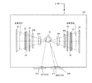
(色ずれ検出用トナー像)
図11は、本実施例の色ずれ検出用トナー像を示す図であり、図1のZ軸−方向から見た中間転写ベルト106を示す図である。CPU801は、色ずれ補正を行う際には、中間転写ベルト106上に図11に示す色ずれ検出用トナー像を形成する。なお、色ずれ検出用トナー像の情報は、予めROM802に記憶されているものとする。中間転写ベルト106上に形成された色ずれ検出用トナー像は、センサ30により検出される。
(Toner image for color misregistration detection)
FIG. 11 is a diagram illustrating a color misregistration detection toner image according to the present exemplary embodiment, and is a diagram illustrating the
色ずれ検出用トナー像は、例えば、中間転写ベルト106の主走査方向(Y軸方向)における両端部と中央部に形成され、色ずれ検出用トナー像が形成された位置に対向して設けられたセンサ30により検出される。センサ30は、より詳細には、中間転写ベルト106の両端部に形成された色ずれ検出用トナー像を検出するセンサ30F、30Rと、中央部に形成された色ずれ検出用トナー像を検出するセンサ30Cを有している。
For example, the color misregistration detection toner images are formed at both ends and the center of the
色ずれ検出用トナー像は、例えば、中間転写ベルト106の搬送方向先頭から、イエロー色のパッチ130Y、マゼンタ色のパッチ130M、シアン色のパッチ130C、ブラック色のパッチ130Bkから構成されている。これらのパッチ130Y〜130Bkが主走査方向に対して所定の傾きをもって形成されたパターン130が、中間転写ベルト106の搬送方向に所定の長さ分繰り返し形成される。
The color misregistration detection toner image includes, for example, a
センサ30は、各パッチ130Y〜130Bkのエッジを検出し、検出結果をCPU801に出力する。CPU801は、例えば、イエロー色のパッチ130Yを基準として、他の色のパッチ130M〜130Bkまでのエッジをそれぞれ検出し、イエロー色に対する各色の色ずれ量を求める。CPU801は、求めた色ずれ量に基づいて、イエロー色に対する各色の補正量(以下、色ずれ補正基準値という)を設定する。なお、色ずれ検出用トナー像をセンサ30により検出することによってCPU801が設定した色ずれ補正基準値には、上述したモードAからモードCの温度変化に起因する色ずれの情報は考慮されていない。
The
(色ずれ補正処理)
図12(a)は、CPU801が実行する本実施例の色ずれ補正処理を示すフローチャートである。CPU801は、画像形成装置100の電源が投入されると以下の処理を開始する。ステップ(以下、Sとする)111でCPU801は、画像形成装置100の各ユニットの動作を開始させる。S112でCPU801は、画像形成を行うことが可能となったか否かを判断し、可能となっていないと判断した場合は処理をS112に戻す。S112でCPU801は、画像形成を行うことが可能になったと判断した場合、S113で中間転写ベルト106上に図11に示す色ずれ検出用トナー像を形成する。S114でCPU801は、上述したように、センサ30により色ずれ検出用トナー像を検出した結果に基づいて、色ずれ補正基準値を設定する。S115でCPU801は、画像形成を行う。なお、S115の処理は後述する。
(Color shift correction processing)
FIG. 12A is a flowchart showing the color misregistration correction processing of this embodiment executed by the
S116でCPU801は、色ずれ検出用トナー像の画像形成が必要か否かを判断する。S116でCPU801は、色ずれ検出用トナー像の画像形成が必要であると判断した場合には、S113の処理に戻る。例えば、CPU801は、不図示のカウンタによりカウントした画像形成が行われた記録シートPの枚数が、1000枚等、所定の枚数に達した場合に、色ずれ検出用トナー像の画像形成が必要であると判断する。また、CPU801は、温度センサ300とは異なる画像形成装置100内に設置された温度検知手段による検知結果に基づいて、色ずれ検出用トナー像の画像形成が必要であると判断する。S116でCPU801は、色ずれ検出用トナー像の画像形成が必要ではないと判断した場合には、S117の処理に進む。S117でCPU801は、次の画像形成のジョブがないか否かを判断し、次のジョブがあると判断した場合は処理をS115に戻す。S117でCPU801は、次のジョブがないと判断した場合は処理を終了する。
In step S116, the
図12(b)は、CPU801が図12(a)のS115の処理で実行する画像形成処理を示すフローチャートである。S115−1でCPU801は、図7、図8で説明したように、温度センサ300の検知結果に基づいて、モードAからモードCの温度変化に起因する色ずれ量を算出する。例えば、温度センサ300の検知結果から温度変動が約4℃であった場合、色ずれ量が約0.1mmと算出されたとする。なお、図9では、温度センサ300の検知結果は、ASIC804を介してCPU801に出力されているが、温度センサ300の検知結果を直接CPU801に出力する構成としてもよい。
FIG. 12B is a flowchart showing the image forming process executed by the
S115−2でCPU801は、S114で求めた色ずれ補正基準値と、S115−1で算出した温度センサ300の検知結果に基づく色ずれ量に基づいて、色ずれ補正条件を決定する。S115−3でCPU801は、S115−2で決定された色ずれ補正条件に基づいて、ASIC804への画像データの出力のタイミング(転送タイミングともいう)を設定する。
In S115-2, the
ここで、図13を用いて、CPU801からASIC804への各色の画像データの転送タイミングの制御について説明する。図13(a)は、図12(a)のS114の処理を実行して得られた色ずれ補正基準値に基づく補正後の各色の画像データの転送タイミングを示す図である。即ち、図13(a)では、モードAからモードCの温度変化に起因する色ずれ量は考慮されていない。図13(a)(i)は、BD808が出力するBD信号(CBk用転送信号)を示す。図13(a)(ii)は、CPU801が生成するYM用転送信号を示す。
Here, the control of the transfer timing of the image data of each color from the
図13(a)(iii)は、CPU801からASIC804に出力される各色の画像データの転送タイミングを示す図である。より詳細には、DATA_Yはイエロー色の画像データ、DATA_Mはマゼンタ色の画像データ、DATA_Cはシアン色の画像データ、DATA_Bkはブラック色の画像データをそれぞれ示す。六角形は各色用転送信号に応じてCPU801からASIC804に転送される1走査分のデータを示す。「scan1」等は記録材Pに形成される画像に対応する画像データを示し、「D」は記録材Pに形成される画像に対応する画像データがないことを示す。
FIGS. 13A and 13I are diagrams illustrating the transfer timing of image data of each color output from the
例えば、CPU801は、S114で色ずれ補正基準値に基づいて、マゼンタ色の画像データの転送を、イエロー色の画像データの転送開始から2走査分遅らせて開始させている。また、CPU801は、シアン色の画像データの転送を、イエロー色の画像データの転送開始から10走査分、ブラック色の画像データの転送を15走査分遅らせて、それぞれ開始させている。なお、図13(a)(i)、図13(a)(ii)の「Y書き出し開始周期」等は、各色の光ビームの照射を開始するタイミングを示している。図13(a)(iii)の画像データの転送を開始するタイミングは、画像データの転送における時間遅延等を考慮して、各色の書き出し開始周期よりも少なくとも1周期前に開始されるようにしている。
For example, in step S114, the
図13(b)は、S115−3で設定された画像データの出力タイミングを示す図であり、図13(b)(i)〜図13(b)(iii)は、図13(a)(i)〜図13(a)(iii)に対応している。例えば、温度センサ300の検知結果に基づき求められた色ずれ量が約0.1mmとなったとする。例えば、600dpiの画像形成装置を想定している場合、色ずれ量0.1mmは約2走査分に相当する。このため、図13(b)(iii)に示すように、マゼンタ色の画像データの転送は、図13(a)(iii)から更に2走査分遅らせて、イエロー色の画像データの転送開始から4走査分後のタイミングで開始される。
FIG. 13B is a diagram showing the output timing of the image data set in S115-3, and FIGS. 13B to 13I are shown in FIG. This corresponds to i) to FIGS. 13 (a) and (iii). For example, it is assumed that the amount of color shift obtained based on the detection result of the
なお、シアン色、ブラック色の走査方向は、図10に示すようにイエロー色、マゼンタ色の走査方向とは逆向きであるため、マゼンタ色をずらす方向と、シアン色、ブラック色をずらす方向は逆になる。このため、シアン色、ブラック色の画像データの転送は、図13(a)(iii)からそれぞれ2走査分早くして開始される。具体的には、シアン色の画像データの転送は、図13(a)(iii)から2走査分早くして、イエロー色の画像データの転送開始から8走査分後のタイミングで開始される。ブラック色の画像データの転送は、図13(a)(iii)から2走査分早くして、イエロー色の画像データの転送開始から13走査分後のタイミングで開始される。なお、図13では、説明を簡易にするために、各感光ドラム102間の距離を差し引いて記載している。 The cyan and black scanning directions are opposite to the yellow and magenta scanning directions, as shown in FIG. 10. Therefore, the direction of shifting the magenta color and the direction of shifting the cyan and black colors are different. Vice versa. For this reason, the transfer of cyan and black image data is started two scans earlier from FIGS. 13 (a) and (iii). Specifically, the transfer of cyan image data is started two scans earlier than that shown in FIGS. 13A and 13 (iii), and is started at a timing eight scans after the start of transfer of yellow image data. The transfer of the black color image data is started by two scans earlier than those in FIGS. 13A and 13 (iii), and is started at a timing 13 scans after the start of the transfer of the yellow color image data. In FIG. 13, the distance between the photosensitive drums 102 is subtracted for the sake of simplicity.
図12(b)の説明に戻る。S115−4でCPU801は、図13(b)(iii)で説明したように、センサ30により色ずれ検出用トナー画像を検出した結果と、温度センサ300により温度を検知した結果とに基づく色ずれ補正量に基づいて、ASIC804に画像データを出力する。
Returning to the description of FIG. In S115-4, the
なお、本実施例では、中間転写ベルト106上に図11の色ずれ検出用トナー像を形成して色ずれの検知結果に基づき、色ずれ補正基準値を求め、更に、温度センサ300の検知結果に基づく補正を行っている。しかし、例えば、中間転写ベルト106上に色ずれ検出用トナー像を形成しない構成としてもよい。即ち、温度センサ300の検知結果に基づき、色ずれ補正を行う構成としてもよい。これにより、色ずれ検出用トナー像を形成することによるトナーの使用量を低減でき、また、この工程によるダウンタイムを低減できる。
In this embodiment, the color misregistration detection toner image shown in FIG. 11 is formed on the
また、本実施例では、温度センサ300の検知結果を、色ずれの補正に用いている。しかし、例えば、画像形成装置100における印刷濃度や、階調性といった画質調整、又はトナーの熱凝固を防ぐための昇温制御等、色ずれ以外の補正、調整に用いてもよい。したがって、本実施例の構成は、カラー画像形成装置に限定されるものではなく、二重壁内に設置された温度検知手段による検知結果に基づき制御を行う画像形成装置であれば適用できる。
In the present embodiment, the detection result of the
以上、本実施例によれば、一つの温度検知手段によって、光走査装置、画像形成装置の雰囲気、結露ヒータ等の温度変動を検知することができる。 As described above, according to the present embodiment, it is possible to detect temperature fluctuations of the optical scanning device, the atmosphere of the image forming apparatus, the dew condensation heater, and the like by one temperature detection unit.
41 回転多面鏡
42 スキャナモータ
71 外壁
72 内壁
90 光学箱
300 温度センサ
500 結露ヒータ
801 CPU
41
Claims (8)
前記複数の感光体を露光するための光ビームを出射する複数の光源と、
前記複数の光源から出射された複数の光ビームがそれぞれ対応する感光体を走査するように前記複数の光ビームを偏向する回転多面鏡と、前記回転多面鏡を回転させるモータと、前記モータが取り付けられた基板と、を有する偏向手段と、
前記偏向手段によって偏向された前記複数の光ビームをそれぞれ対応する感光体に導く光学部材と、
前記偏向手段及び前記光学部材が設置される設置面と、前記設置面から立設し前記偏向手段及び前記光学部材を取り囲む第一の側壁と、前記第一の側壁を取り囲む第二の側壁と、を有する筐体と、
前記光ビームの走査方向において前記筐体に隣接して配置された熱源と、
前記第一の側壁と前記第二の側壁の間に設けられた温度検知手段と、
前記複数の感光体上のトナー像を記録紙に転写するための転写手段と、
前記温度検知手段の検知結果に基づいて前記複数の感光体から記録紙上に転写されるトナー像間の色ずれを補正する制御手段と、
を備え、
前記温度検知手段は、前記第二の側壁のうちの前記熱源と対向する部分と、前記第一の側壁のうち前記第二の側壁のうちの前記熱源と対向する部分と対向する部分と、の間に配置されていることを特徴とする画像形成装置。 A plurality of photoreceptors each carrying a toner image of a different color ;
A plurality of light sources that emit light beams for exposing the plurality of photosensitive members;
A rotating polygon mirror that deflects the plurality of light beams so that a plurality of light beams emitted from the plurality of light sources respectively scan corresponding photoreceptors, a motor that rotates the rotating polygon mirror, and the motor are attached A deflecting means comprising:
Optical members for guiding the plurality of light beams deflected by the deflecting means to corresponding photoreceptors,
A mounting surface of said deflecting means and the optical member is mounted, a first side wall erected from the mounting surface surrounding the said deflection means and said optical member, and the front Stories second sidewall surrounding the first sidewall A housing having
A heat source disposed adjacent to the housing in the scanning direction of the light beam ;
Temperature detecting means provided between the first side wall and the second side wall;
Transfer means for transferring toner images on the plurality of photosensitive members to a recording paper;
Control means for correcting color misregistration between toner images transferred onto the recording paper from the plurality of photoconductors based on the detection result of the temperature detection means;
Equipped with a,
The temperature detection means includes: a portion of the second side wall facing the heat source; and a portion of the first side wall facing the portion of the second side wall facing the heat source. an image forming apparatus comprising that you have placed between.
前記光学部材は、複数のレンズ及び反射ミラーからなり、前記偏向手段によって偏向された光ビームを前記感光体に導くレンズ及び反射ミラーのうち、前記光ビームが最初に入射する2つの第1のレンズを有し、
前記偏向手段は、前記2つの第1のレンズの間に位置することを特徴とする請求項1から請求項6のいずれか1項に記載の画像形成装置。 A plurality of the photoreceptors;
The optical member includes a plurality of lenses and a reflecting mirror, and among the lens and the reflecting mirror that guides the light beam deflected by the deflecting unit to the photosensitive member, two first lenses on which the light beam first enters. Have
The image forming apparatus according to claim 1, wherein the deflecting unit is located between the two first lenses.
Priority Applications (1)
| Application Number | Priority Date | Filing Date | Title |
|---|---|---|---|
| JP2015226874A JP6594174B2 (en) | 2015-11-19 | 2015-11-19 | Image forming apparatus |
Applications Claiming Priority (1)
| Application Number | Priority Date | Filing Date | Title |
|---|---|---|---|
| JP2015226874A JP6594174B2 (en) | 2015-11-19 | 2015-11-19 | Image forming apparatus |
Publications (3)
| Publication Number | Publication Date |
|---|---|
| JP2017097070A JP2017097070A (en) | 2017-06-01 |
| JP2017097070A5 JP2017097070A5 (en) | 2018-12-27 |
| JP6594174B2 true JP6594174B2 (en) | 2019-10-23 |
Family
ID=58817717
Family Applications (1)
| Application Number | Title | Priority Date | Filing Date |
|---|---|---|---|
| JP2015226874A Expired - Fee Related JP6594174B2 (en) | 2015-11-19 | 2015-11-19 | Image forming apparatus |
Country Status (1)
| Country | Link |
|---|---|
| JP (1) | JP6594174B2 (en) |
Families Citing this family (4)
| Publication number | Priority date | Publication date | Assignee | Title |
|---|---|---|---|---|
| JP6938215B2 (en) * | 2017-05-16 | 2021-09-22 | 株式会社イノアック住環境 | Heat exchanger |
| JP2018205659A (en) * | 2017-06-09 | 2018-12-27 | キヤノン株式会社 | Image formation apparatus |
| JP7199899B2 (en) * | 2018-10-09 | 2023-01-06 | キヤノン株式会社 | image forming device |
| JP7096530B2 (en) | 2018-10-17 | 2022-07-06 | セイコーエプソン株式会社 | Recording device |
Family Cites Families (10)
| Publication number | Priority date | Publication date | Assignee | Title |
|---|---|---|---|---|
| JPH04127116A (en) * | 1990-06-25 | 1992-04-28 | Ricoh Co Ltd | Image forming device |
| JP2003295739A (en) * | 2002-04-04 | 2003-10-15 | Canon Inc | Color image forming apparatus |
| JP2006227577A (en) * | 2005-01-19 | 2006-08-31 | Ricoh Co Ltd | Optical scanner and image forming apparatus |
| JP5239211B2 (en) * | 2006-07-31 | 2013-07-17 | 株式会社リコー | Image forming apparatus |
| JP2012128068A (en) * | 2010-12-14 | 2012-07-05 | Canon Inc | Scanning type optical device |
| JP5490061B2 (en) * | 2011-07-12 | 2014-05-14 | シャープ株式会社 | Registration method for image forming apparatus and image forming apparatus |
| JP6305160B2 (en) * | 2014-03-31 | 2018-04-04 | キヤノン株式会社 | Optical scanning apparatus and image forming apparatus |
| JP6170461B2 (en) * | 2014-04-10 | 2017-07-26 | 京セラドキュメントソリューションズ株式会社 | Optical scanning device and image forming apparatus including the optical scanning device |
| JP6452380B2 (en) * | 2014-10-22 | 2019-01-16 | キヤノン株式会社 | Image forming apparatus |
| US9298160B1 (en) * | 2015-05-28 | 2016-03-29 | Kabushiki Kaisha Toshiba | Image forming apparatus and cooling control method for image forming apparatus |
-
2015
- 2015-11-19 JP JP2015226874A patent/JP6594174B2/en not_active Expired - Fee Related
Also Published As
| Publication number | Publication date |
|---|---|
| JP2017097070A (en) | 2017-06-01 |
Similar Documents
| Publication | Publication Date | Title |
|---|---|---|
| JP6594174B2 (en) | Image forming apparatus | |
| US9389533B2 (en) | Image forming apparatus capable of correcting position of image to be formed | |
| JP6879374B2 (en) | Image forming device | |
| JP6305160B2 (en) | Optical scanning apparatus and image forming apparatus | |
| US10126689B2 (en) | Image forming apparatus | |
| US9851655B2 (en) | Image forming apparatus and optical scanning apparatus | |
| JP5478650B2 (en) | Optical scanning apparatus and image forming apparatus | |
| JP6043380B2 (en) | Optical scanning apparatus, image forming apparatus including the optical scanning apparatus, and position adjustment method for synchronization detection sensor mounted on the optical scanning apparatus | |
| JP6304067B2 (en) | Image forming apparatus | |
| JP6292960B2 (en) | Image forming apparatus | |
| JP6031418B2 (en) | Optical scanning device and image forming apparatus using the same | |
| JP4617731B2 (en) | Image forming apparatus | |
| JP4935323B2 (en) | Image forming apparatus | |
| JP2019188734A (en) | Image formation device and method for controlling the same | |
| JP6663136B2 (en) | Optical scanning device and image forming apparatus provided with the optical scanning device | |
| JP2007163765A (en) | Image forming apparatus | |
| JP2006030731A (en) | Optical scanning device and image forming apparatus | |
| JP2006184650A (en) | Scanning optical apparatus and image forming apparatus | |
| JP6414494B2 (en) | Image forming apparatus | |
| JP6264252B2 (en) | Optical scanning device and image forming apparatus having the same | |
| JP2020020968A (en) | Image forming apparatus | |
| JP2020046647A (en) | Image formation apparatus | |
| JP2020013039A (en) | Image forming apparatus | |
| JP2009126002A (en) | Image forming apparatus | |
| US20150277271A1 (en) | Image Forming Apparatus, Method for Controlling Image Forming Conditions, and Non-Transitory Computer-Readable Medium Storing Computer-Readable Instructions |
Legal Events
| Date | Code | Title | Description |
|---|---|---|---|
| RD03 | Notification of appointment of power of attorney |
Free format text: JAPANESE INTERMEDIATE CODE: A7423 Effective date: 20160215 |
|
| RD04 | Notification of resignation of power of attorney |
Free format text: JAPANESE INTERMEDIATE CODE: A7424 Effective date: 20160215 |
|
| RD04 | Notification of resignation of power of attorney |
Free format text: JAPANESE INTERMEDIATE CODE: A7424 Effective date: 20171201 |
|
| A521 | Request for written amendment filed |
Free format text: JAPANESE INTERMEDIATE CODE: A523 Effective date: 20181116 |
|
| A621 | Written request for application examination |
Free format text: JAPANESE INTERMEDIATE CODE: A621 Effective date: 20181116 |
|
| TRDD | Decision of grant or rejection written | ||
| A01 | Written decision to grant a patent or to grant a registration (utility model) |
Free format text: JAPANESE INTERMEDIATE CODE: A01 Effective date: 20190827 |
|
| A977 | Report on retrieval |
Free format text: JAPANESE INTERMEDIATE CODE: A971007 Effective date: 20190828 |
|
| A61 | First payment of annual fees (during grant procedure) |
Free format text: JAPANESE INTERMEDIATE CODE: A61 Effective date: 20190924 |
|
| R151 | Written notification of patent or utility model registration |
Ref document number: 6594174 Country of ref document: JP Free format text: JAPANESE INTERMEDIATE CODE: R151 |
|
| LAPS | Cancellation because of no payment of annual fees |