JP6593754B2 - Hydrogen generator and fuel cell system - Google Patents
Hydrogen generator and fuel cell system Download PDFInfo
- Publication number
- JP6593754B2 JP6593754B2 JP2015211700A JP2015211700A JP6593754B2 JP 6593754 B2 JP6593754 B2 JP 6593754B2 JP 2015211700 A JP2015211700 A JP 2015211700A JP 2015211700 A JP2015211700 A JP 2015211700A JP 6593754 B2 JP6593754 B2 JP 6593754B2
- Authority
- JP
- Japan
- Prior art keywords
- gas
- hydrogen
- flow rate
- raw material
- recycle
- Prior art date
- Legal status (The legal status is an assumption and is not a legal conclusion. Google has not performed a legal analysis and makes no representation as to the accuracy of the status listed.)
- Active
Links
Images


Classifications
-
- H—ELECTRICITY
- H01—ELECTRIC ELEMENTS
- H01M—PROCESSES OR MEANS, e.g. BATTERIES, FOR THE DIRECT CONVERSION OF CHEMICAL ENERGY INTO ELECTRICAL ENERGY
- H01M8/00—Fuel cells; Manufacture thereof
- H01M8/06—Combination of fuel cells with means for production of reactants or for treatment of residues
- H01M8/0606—Combination of fuel cells with means for production of reactants or for treatment of residues with means for production of gaseous reactants
- H01M8/0612—Combination of fuel cells with means for production of reactants or for treatment of residues with means for production of gaseous reactants from carbon-containing material
- H01M8/0618—Reforming processes, e.g. autothermal, partial oxidation or steam reforming
-
- B—PERFORMING OPERATIONS; TRANSPORTING
- B01—PHYSICAL OR CHEMICAL PROCESSES OR APPARATUS IN GENERAL
- B01J—CHEMICAL OR PHYSICAL PROCESSES, e.g. CATALYSIS OR COLLOID CHEMISTRY; THEIR RELEVANT APPARATUS
- B01J19/00—Chemical, physical or physico-chemical processes in general; Their relevant apparatus
- B01J19/24—Stationary reactors without moving elements inside
-
- C—CHEMISTRY; METALLURGY
- C01—INORGANIC CHEMISTRY
- C01B—NON-METALLIC ELEMENTS; COMPOUNDS THEREOF; METALLOIDS OR COMPOUNDS THEREOF NOT COVERED BY SUBCLASS C01C
- C01B3/00—Hydrogen; Gaseous mixtures containing hydrogen; Separation of hydrogen from mixtures containing it; Purification of hydrogen
- C01B3/02—Production of hydrogen or of gaseous mixtures containing a substantial proportion of hydrogen
- C01B3/32—Production of hydrogen or of gaseous mixtures containing a substantial proportion of hydrogen by reaction of gaseous or liquid organic compounds with gasifying agents, e.g. water, carbon dioxide, air
- C01B3/34—Production of hydrogen or of gaseous mixtures containing a substantial proportion of hydrogen by reaction of gaseous or liquid organic compounds with gasifying agents, e.g. water, carbon dioxide, air by reaction of hydrocarbons with gasifying agents
-
- H—ELECTRICITY
- H01—ELECTRIC ELEMENTS
- H01M—PROCESSES OR MEANS, e.g. BATTERIES, FOR THE DIRECT CONVERSION OF CHEMICAL ENERGY INTO ELECTRICAL ENERGY
- H01M8/00—Fuel cells; Manufacture thereof
- H01M8/06—Combination of fuel cells with means for production of reactants or for treatment of residues
- H01M8/0662—Treatment of gaseous reactants or gaseous residues, e.g. cleaning
- H01M8/0675—Removal of sulfur
-
- B—PERFORMING OPERATIONS; TRANSPORTING
- B01—PHYSICAL OR CHEMICAL PROCESSES OR APPARATUS IN GENERAL
- B01J—CHEMICAL OR PHYSICAL PROCESSES, e.g. CATALYSIS OR COLLOID CHEMISTRY; THEIR RELEVANT APPARATUS
- B01J2219/00—Chemical, physical or physico-chemical processes in general; Their relevant apparatus
- B01J2219/00049—Controlling or regulating processes
- B01J2219/00164—Controlling or regulating processes controlling the flow
-
- B—PERFORMING OPERATIONS; TRANSPORTING
- B01—PHYSICAL OR CHEMICAL PROCESSES OR APPARATUS IN GENERAL
- B01J—CHEMICAL OR PHYSICAL PROCESSES, e.g. CATALYSIS OR COLLOID CHEMISTRY; THEIR RELEVANT APPARATUS
- B01J2219/00—Chemical, physical or physico-chemical processes in general; Their relevant apparatus
- B01J2219/24—Stationary reactors without moving elements inside
-
- C—CHEMISTRY; METALLURGY
- C01—INORGANIC CHEMISTRY
- C01B—NON-METALLIC ELEMENTS; COMPOUNDS THEREOF; METALLOIDS OR COMPOUNDS THEREOF NOT COVERED BY SUBCLASS C01C
- C01B2203/00—Integrated processes for the production of hydrogen or synthesis gas
- C01B2203/02—Processes for making hydrogen or synthesis gas
- C01B2203/0205—Processes for making hydrogen or synthesis gas containing a reforming step
-
- C—CHEMISTRY; METALLURGY
- C01—INORGANIC CHEMISTRY
- C01B—NON-METALLIC ELEMENTS; COMPOUNDS THEREOF; METALLOIDS OR COMPOUNDS THEREOF NOT COVERED BY SUBCLASS C01C
- C01B2203/00—Integrated processes for the production of hydrogen or synthesis gas
- C01B2203/06—Integration with other chemical processes
- C01B2203/066—Integration with other chemical processes with fuel cells
-
- C—CHEMISTRY; METALLURGY
- C01—INORGANIC CHEMISTRY
- C01B—NON-METALLIC ELEMENTS; COMPOUNDS THEREOF; METALLOIDS OR COMPOUNDS THEREOF NOT COVERED BY SUBCLASS C01C
- C01B2203/00—Integrated processes for the production of hydrogen or synthesis gas
- C01B2203/12—Feeding the process for making hydrogen or synthesis gas
- C01B2203/1258—Pre-treatment of the feed
- C01B2203/1264—Catalytic pre-treatment of the feed
- C01B2203/127—Catalytic desulfurisation
-
- C—CHEMISTRY; METALLURGY
- C01—INORGANIC CHEMISTRY
- C01B—NON-METALLIC ELEMENTS; COMPOUNDS THEREOF; METALLOIDS OR COMPOUNDS THEREOF NOT COVERED BY SUBCLASS C01C
- C01B2203/00—Integrated processes for the production of hydrogen or synthesis gas
- C01B2203/14—Details of the flowsheet
- C01B2203/148—Details of the flowsheet involving a recycle stream to the feed of the process for making hydrogen or synthesis gas
-
- C—CHEMISTRY; METALLURGY
- C01—INORGANIC CHEMISTRY
- C01B—NON-METALLIC ELEMENTS; COMPOUNDS THEREOF; METALLOIDS OR COMPOUNDS THEREOF NOT COVERED BY SUBCLASS C01C
- C01B2203/00—Integrated processes for the production of hydrogen or synthesis gas
- C01B2203/16—Controlling the process
- C01B2203/1614—Controlling the temperature
- C01B2203/1619—Measuring the temperature
-
- C—CHEMISTRY; METALLURGY
- C01—INORGANIC CHEMISTRY
- C01B—NON-METALLIC ELEMENTS; COMPOUNDS THEREOF; METALLOIDS OR COMPOUNDS THEREOF NOT COVERED BY SUBCLASS C01C
- C01B2203/00—Integrated processes for the production of hydrogen or synthesis gas
- C01B2203/16—Controlling the process
- C01B2203/169—Controlling the feed
-
- Y—GENERAL TAGGING OF NEW TECHNOLOGICAL DEVELOPMENTS; GENERAL TAGGING OF CROSS-SECTIONAL TECHNOLOGIES SPANNING OVER SEVERAL SECTIONS OF THE IPC; TECHNICAL SUBJECTS COVERED BY FORMER USPC CROSS-REFERENCE ART COLLECTIONS [XRACs] AND DIGESTS
- Y02—TECHNOLOGIES OR APPLICATIONS FOR MITIGATION OR ADAPTATION AGAINST CLIMATE CHANGE
- Y02E—REDUCTION OF GREENHOUSE GAS [GHG] EMISSIONS, RELATED TO ENERGY GENERATION, TRANSMISSION OR DISTRIBUTION
- Y02E60/00—Enabling technologies; Technologies with a potential or indirect contribution to GHG emissions mitigation
- Y02E60/30—Hydrogen technology
- Y02E60/50—Fuel cells
Description
本発明は、原料ガスに含まれる硫黄を水素含有ガスの一部と反応させて除去する水添脱硫器を備えている水素生成装置および燃料電池システムに関するものである。 The present invention relates to a hydrogen generator and a fuel cell system including a hydrodesulfurizer that removes sulfur contained in a raw material gas by reacting with part of a hydrogen-containing gas.
原料ガス(原燃料ガス)として炭化水素を用いた燃料電池システムでは、たとえば、改質触媒の存在の下、水蒸気を用いた水蒸気改質により原料ガスを改質している。この原料ガスには付臭剤としての硫黄化合物や原料由来の硫黄化合物が含まれている。これらの硫黄が改質触媒を被毒するため、硫黄化合物を原料ガスから除去する必要がある。 In a fuel cell system using hydrocarbons as a source gas (raw fuel gas), for example, the source gas is reformed by steam reforming using steam in the presence of a reforming catalyst. This source gas contains a sulfur compound as an odorant and a source-derived sulfur compound. Since these sulfur poison the reforming catalyst, it is necessary to remove the sulfur compound from the raw material gas.
硫黄を除去する脱硫装置としては、たとえば、水添脱硫装置が挙げられる。この水添脱硫装置では、触媒(Ni−Mo系、Co−Mo系)の存在下で硫黄を水素と反応させ、生成された硫化水素を酸化亜鉛に吸着させる水添脱硫反応が行われている。このように水添脱硫反応では水素が必要であるため、改質器で生成された燃料ガスの一部を脱硫器に供給するように構成されている(たとえば、特許文献1参照)。 Examples of the desulfurization apparatus that removes sulfur include a hydrodesulfurization apparatus. In this hydrodesulfurization apparatus, a hydrodesulfurization reaction is performed in which sulfur is reacted with hydrogen in the presence of a catalyst (Ni-Mo system, Co-Mo system), and the generated hydrogen sulfide is adsorbed on zinc oxide. . As described above, since hydrogen is required in the hydrodesulfurization reaction, a part of the fuel gas generated in the reformer is supplied to the desulfurizer (see, for example, Patent Document 1).
しかしながら、上記特許文献1に記載された従来技術には、水素生成装置の効率低下を抑制するという観点から未だ改善の余地がある。本発明は、この従来の課題を解決するもので、水素生成装置の効率低下を抑制することができる水素生成装置および燃料電池システムを提供することを目的とする。
However, there is still room for improvement in the prior art described in
本発明のある態様に係る燃料電池システムは、原料ガスを用いて改質反応により水素含有ガスを生成する改質器と、前記改質器の温度を検知する温度検知器と、前記原料ガスに含まれる硫黄を水添脱硫反応により除去する水添脱硫器と、前記水素含有ガスの一部のリサイクルガスを前記水添脱硫器に供給するリサイクル流路と、前記リサイクルガスと前記原料ガスとが合流する部分より上流の前記原料ガスが流れる流路に設けられ、前記原料ガスの流量を検知する原料ガス流量検知器と、前記改質器の温度、前記原料ガスの流量および前記リサイクルガスの流量に基づいて前記リサイクルガスの流量を調整する制御器と、を備えている。 A fuel cell system according to an aspect of the present invention includes a reformer that generates a hydrogen-containing gas by a reforming reaction using a raw material gas, a temperature detector that detects the temperature of the reformer, and the raw material gas. A hydrodesulfurizer that removes sulfur contained in the hydrodesulfurization reaction; a recycle flow path for supplying a part of the hydrogen-containing gas recycle gas to the hydrodesulfurizer; and the recycle gas and the source gas. A raw material gas flow detector for detecting the flow rate of the raw material gas provided in a flow path through which the raw material gas flows upstream from the joining portion, the temperature of the reformer, the flow rate of the raw material gas, and the flow rate of the recycle gas And a controller for adjusting the flow rate of the recycle gas based on the above.
本発明は、水素生成装置および燃料電池システムにおいて効率の低下を抑制することが可能であるという効果を奏する。 The present invention has an effect that it is possible to suppress a decrease in efficiency in a hydrogen generator and a fuel cell system.
本発明の上記目的、他の目的、特徴、および利点は、添付図面参照の下、以下の好適な実施態様の詳細な説明から明らかにされる。 The above object, other objects, features, and advantages of the present invention will become apparent from the following detailed description of preferred embodiments with reference to the accompanying drawings.
(本発明の基礎となった知見)
本発明者らは、水素生成装置および燃料電池システムの効率低下を抑制することについて検討した。上記特許文献1の燃料改質システムでは、原燃料とリサイクルガスとの流量比が一定になるようにリサイクルガスの流量を調整している。しかしながら、燃料ガスの水素含有率は改質部の温度により変動する。このため、脱硫部に供給される水素量が水添脱硫反応に必要な水素量より少ないと、水添脱硫反応が十分に行われない。よって、原燃料ガスに残った硫黄により改質触媒が劣化して、水素生成装置における効率が低下してしまう。
(Knowledge that became the basis of the present invention)
The present inventors have studied to suppress the efficiency reduction of the hydrogen generator and the fuel cell system. In the fuel reforming system of
そこで、本発明者などは、改質器の温度、原料ガスの流量およびリサイクルガスの流量に基づいてリサイクルガスの流量を調整することにより、水素生成装置の効率の低下の抑制、延いては、燃料電池システムの効率の低下の抑制を図ることができることを見出した。本発明はこの知見に基づいてなされたものである。 Therefore, the present inventors, for example, adjust the flow rate of the recycle gas based on the temperature of the reformer, the flow rate of the raw material gas, and the flow rate of the recycle gas, thereby suppressing the decrease in efficiency of the hydrogen generator, It has been found that the reduction in the efficiency of the fuel cell system can be suppressed. The present invention has been made based on this finding.
本発明の第1の態様に係る水素生成装置は、原料ガスを用いて改質反応により水素含有ガスを生成する改質器と、前記改質器の温度を検知する温度検知器と、前記原料ガスに含まれる硫黄を水添脱硫反応により除去する水添脱硫器と、前記水素含有ガスの一部のリサイクルガスを前記水添脱硫器に供給するリサイクル流路と、前記リサイクルガスと前記原料ガスとが合流する部分より上流の前記原料ガスが流れる流路に設けられ、前記原料ガスの流量を検知する原料ガス流量検知器と、前記改質器の温度、前記原料ガスの流量および前記リサイクルガスの流量に基づいて前記リサイクルガスの流量を調整する制御器と、を備えている。 The hydrogen generator according to the first aspect of the present invention includes a reformer that generates a hydrogen-containing gas by a reforming reaction using a raw material gas, a temperature detector that detects the temperature of the reformer, and the raw material A hydrodesulfurizer for removing sulfur contained in the gas by a hydrodesulfurization reaction; a recycle passage for supplying a part of the hydrogen-containing gas recycle gas to the hydrodesulfurizer; the recycle gas and the source gas A source gas flow rate detector for detecting the flow rate of the source gas, a temperature of the reformer, a flow rate of the source gas, and the recycle gas. And a controller for adjusting the flow rate of the recycled gas based on the flow rate of the recycle gas.
これにより、改質器の温度などの変化によりリサイクルガスの水素含有率が変化しても、それに伴いリサイクルガスの流量が制御される。よって、リサイクルガスの水素含有量が水添脱硫反応に必要な水素量を満たすため、水添脱硫反応により原料ガスから硫黄をより確実に除去することができる。よって、硫黄による触媒等の劣化を抑え、水素生成装置の効率低下を抑制することができる。 As a result, even if the hydrogen content of the recycle gas changes due to a change in the temperature of the reformer, the flow rate of the recycle gas is controlled accordingly. Therefore, since the hydrogen content of the recycle gas satisfies the hydrogen amount necessary for the hydrodesulfurization reaction, sulfur can be more reliably removed from the raw material gas by the hydrodesulfurization reaction. Therefore, it is possible to suppress deterioration of the catalyst and the like due to sulfur and to suppress a decrease in efficiency of the hydrogen generator.
本発明の第2の態様に係る水素生成装置は、第1の態様において、前記制御器は、前記改質器の温度および前記リサイクルガスの流量に基づいた前記リサイクルガスに含まれる水素の量が、還流後の前記原料ガスに含有される水素の量が一定となるように、前記リサイクルガスの流量を調整するよう構成されている。これにより、水添脱硫反応により原料ガスから硫黄をより確実に除去し、水素生成装置の効率低下を抑制することができる。 The hydrogen generator according to a second aspect of the present invention is the hydrogen generator according to the first aspect, wherein the controller has an amount of hydrogen contained in the recycle gas based on the temperature of the reformer and the flow rate of the recycle gas. The flow rate of the recycle gas is adjusted so that the amount of hydrogen contained in the source gas after reflux is constant. Thereby, sulfur can be more reliably removed from the raw material gas by the hydrodesulfurization reaction, and a reduction in efficiency of the hydrogen generator can be suppressed.
本発明の第3の態様に係る水素生成装置は、第1または第2の態様において、前記制御器は、前記リサイクルガスに含まれる水素の量が所定値以下になるように、前記リサイクルガスの流量を調整するよう構成されている。これにより、たとえば、原料ガス流量調整器の能力に基づいた所定値に設定すると、この所定値以下にリサイクルガスの水素含有量がなるようにリサイクルガスの流量が調整される。このため、リサイクルガスの流量増加により原料ガスの流量が原料ガス流量調整器の能力より大きくなることが防がれる。
本発明の第4の態様に係る水素生成装置は、第1〜第3のいずれか1つの態様において、前記リサイクルガスの流量を検知するリサイクルガス流量検知器を備える。
The hydrogen generator according to a third aspect of the present invention is the hydrogen generator according to the first or second aspect, wherein the controller controls the recycle gas so that the amount of hydrogen contained in the recycle gas is a predetermined value or less. It is configured to adjust the flow rate. Thereby, for example, when a predetermined value based on the capability of the raw material gas flow regulator is set, the flow rate of the recycle gas is adjusted so that the hydrogen content of the recycle gas is below this predetermined value. For this reason, it is prevented that the flow rate of the source gas becomes larger than the capacity of the source gas flow rate regulator due to the increase in the flow rate of the recycle gas.
A hydrogen generation device according to a fourth aspect of the present invention includes, in any one of the first to third aspects, a recycle gas flow rate detector that detects a flow rate of the recycle gas.
本発明の第5の態様に係る燃料電池システムは、第1〜第4のいずれか1つの態様の水素生成装置と、前記水素生成装置から供給される水素含有ガスを用いて発電する燃料電池と、を備えている。これにより、水添脱硫反応により原料ガスから硫黄をより確実に除去されるため、硫黄による燃料電池の電極等の劣化が抑えられ、燃料電池システムの効率低下を抑制することができる。 A fuel cell system according to a fifth aspect of the present invention includes a hydrogen generator according to any one of the first to fourth aspects, and a fuel cell that generates power using a hydrogen-containing gas supplied from the hydrogen generator. It is equipped with. Thereby, since sulfur is more reliably removed from the raw material gas by the hydrodesulfurization reaction, deterioration of the electrode of the fuel cell due to sulfur can be suppressed, and a decrease in efficiency of the fuel cell system can be suppressed.
本発明の第6の態様に係る燃料電池システムは、第5の態様において、前記燃料電池は固体酸化物形燃料電池である。これにより、水素生成装置に変成器を設けない固体酸化物形燃料電池であっても、水添脱硫反応により原料ガスから硫黄をより確実に除去して、燃料電池システムの効率低下を抑制することができる。 In the fuel cell system according to a sixth aspect of the present invention, in the fifth aspect, the fuel cell is a solid oxide fuel cell. As a result, even in the case of a solid oxide fuel cell in which a hydrogen generator is not provided with a transformer, sulfur can be more reliably removed from the raw material gas by the hydrodesulfurization reaction, thereby suppressing a decrease in efficiency of the fuel cell system. Can do.
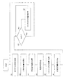
(実施の形態1)
実施の形態1に係る水素生成装置100の構成について図1を参照して説明する。図1は、実施の形態1に係る水素生成装置100の構成の一例を概略的に示すブロック図である。水素生成装置100は、水添脱硫器1、改質器2、温度検知器2a、原料ガス流量検知器4、原料ガス流量調整器5、リサイクルガス流量調整器6、原料ガス流路7a、水素含有ガス流路7b、リサイクル流路9および制御器10を備えている。
(Embodiment 1)
The configuration of the
原料ガス流路7aは、原料ガスを改質器2に供給するための流路である。原料ガス流路7aは、原料ガス源(図示せず)と改質器2とを接続する。原料ガス源としては、たとえば、原料ガスボンベ、原料ガスインフラなどが挙げられる。原料ガスは、所定の圧力で原料ガス源から供給される。
The
原料ガスは、少なくとも炭素および水素から構成されている有機化合物を含むガスであって、たとえば、メタンを主成分とする都市ガスおよび天然ガス、ならびに、LPGなどが挙げられる。原料ガスは、原料由来または付臭剤として硫黄化合物を含んでいる。たとえば、都市ガスは、ジメチルスルフィド(dimethyl sulfide ;C2H6S、DMS)を付
臭剤として含有している。DMS以外の付臭剤としては、TBM(C4H10S)およびTHT(C4H8S)などが例示される。
The source gas is a gas containing an organic compound composed of at least carbon and hydrogen, and examples thereof include city gas and natural gas mainly composed of methane, and LPG. The raw material gas contains a sulfur compound as a raw material-derived or odorant. For example, city gas contains dimethyl sulfide (C 2 H 6 S, DMS) as an odorant. Examples of odorants other than DMS include TBM (C 4 H 10 S) and THT (C 4 H 8 S).
原料ガス流量検知器4は、原料ガス源から供給される原料ガスの流量(単位時間当たりに流れる原料ガスの体積または質量)を検知するセンサである。原料ガス流量検知器4は、リサイクルガスと原料ガスとが合流する部分より上流において原料ガス流路7aに設けられている。
The source gas
原料ガス流量調整器5は、原料ガス流路7aを流れる原料ガスの流量を調整する機器である。原料ガス流量調整器5は、原料ガス流量検知器4の下流側において原料ガス流路7aに設けられている。原料ガス流量調整器5は、たとえば、昇圧器と流量調整弁により構成されているが、これらのいずれか一方により構成されていてもよい。昇圧器には、たとえば、定容積型ポンプが用いられるが、これに限定されるものではない。
The source gas
水添脱硫器1は、原料ガス中の硫黄を水添脱硫反応により除去する反応器である。水添脱硫器1は、原料ガス流量調整器5の下流側において原料ガス流路7aに設けられる。水添脱硫器1は、容器(図示せず)を備え、容器に水添脱硫用の脱硫剤が充填されている。
The
水添脱流用の脱硫剤は、たとえば、反応触媒および吸着触媒により構成されている。反応触媒は、原料ガス中の硫黄化合物が水素と反応する水添脱硫反応の触媒であって、たとえば、Ni−Mo系またはCo−Mo系触媒である。吸着触媒は、反応触媒より原料ガスの流れの下流に設けられている。吸着触媒は、水添脱硫反応により生成された硫化水素を吸着する硫黄吸着剤であって、たとえば、ZnO系触媒またはCuZn系触媒である。このような、Ni−Mo系触媒、Co−Mo系触媒、ZnO系触媒またはCuZn系触媒を用いた脱硫剤は、単位体積あたりの硫黄成分除去量が大きい。よって、所望の硫黄濃度まで硫黄を除去するために必要な脱硫剤の量は少なくてすむ。 The desulfurization agent for hydrodesulfurization is composed of, for example, a reaction catalyst and an adsorption catalyst. The reaction catalyst is a hydrodesulfurization reaction catalyst in which a sulfur compound in the raw material gas reacts with hydrogen, and is, for example, a Ni—Mo based or Co—Mo based catalyst. The adsorption catalyst is provided downstream of the flow of the raw material gas from the reaction catalyst. The adsorption catalyst is a sulfur adsorbent that adsorbs hydrogen sulfide generated by the hydrodesulfurization reaction, and is, for example, a ZnO-based catalyst or a CuZn-based catalyst. Such a desulfurization agent using a Ni—Mo based catalyst, a Co—Mo based catalyst, a ZnO based catalyst or a CuZn based catalyst has a large sulfur component removal amount per unit volume. Thus, less desulfurizing agent is required to remove sulfur to the desired sulfur concentration.
このCuZn系触媒の水添脱硫反応に適した温度は、たとえば、10〜400℃、好ましくは150〜300℃である。CuZn系触媒は、低温では主に物理吸着を行い、高温では化学吸着(H2S+ZnO→H2O+ZnS)を行う。この吸着によって、原料ガスに含まれる硫黄含有量は、たとえば、1vol ppb(parts per billion)以下になる。通常の硫黄含有量は、たとえば、0.1vol ppb以下になる。 The temperature suitable for the hydrodesulfurization reaction of this CuZn-based catalyst is, for example, 10 to 400 ° C, preferably 150 to 300 ° C. The CuZn-based catalyst mainly performs physical adsorption at a low temperature and performs chemical adsorption (H 2 S + ZnO → H 2 O + ZnS) at a high temperature. By this adsorption, the sulfur content contained in the raw material gas becomes, for example, 1 vol ppb (parts per billion) or less. The normal sulfur content is, for example, 0.1 vol ppb or less.
たとえば、DMSは、以下の反応式(1)、(2)に示す水添脱硫反応によって原料ガスから除去される。 For example, DMS is removed from the raw material gas by the hydrodesulfurization reaction shown in the following reaction formulas (1) and (2).
C2H6S+2H2→2CH4+H2S ・・・(1)
H2S+ZnO→H2O+ZnS ・・・(2)
なお、水添脱硫用の脱硫剤は、上記反応触媒および吸着触媒に限定されず、たとえば、CuZn系触媒のみを脱硫剤と用いることもできる。CuZn系触媒は、硫黄化合物を水素と水添脱硫反応させる機能、および、硫化水素を吸着する機能を併せ持つ。
C 2 H 6 S + 2H 2 → 2CH 4 + H 2 S (1)
H 2 S + ZnO → H 2 O + ZnS (2)
Note that the desulfurization agent for hydrodesulfurization is not limited to the reaction catalyst and the adsorption catalyst, and for example, only a CuZn-based catalyst can be used as the desulfurization agent. The CuZn-based catalyst has both a function of hydrodesulfurizing a sulfur compound with hydrogen and a function of adsorbing hydrogen sulfide.
改質器2は、原料ガスを改質反応して水素含有ガスを生成する反応器である。改質器2は、水添脱硫器1の下流側において原料ガス流路7aに接続され、また、水素含有ガス流路7bに接続されている。改質器2には、改質反応の触媒(改質触媒)が充填されている。改質触媒としては、たとえば、Al2O3(アルミナ)の球体表面にNiを含浸して担持したもの、または、Al2O3の球体表面にルテニウムを付与したものが例示される。
The
改質反応は、いずれの形態であってもよく、たとえば、水蒸気改質反応、オートサーマル反応および部分酸化反応などが挙げられる。ただし、水蒸気改質反応が他に比べて高い効率を有している。改質器2には、各改質反応に必要な機器が適宜設けられている。たとえば、水蒸気改質反応では、改質器2を加熱する燃焼器(図示せず)、水蒸気を生成する蒸発器(図示せず)、および、蒸発器に水を供給する水供給器(図示せず)が設けられる。オートサーマル反応では、改質器2に空気を供給する空気供給器(図示せず)が設けられる。
The reforming reaction may take any form, and examples thereof include a steam reforming reaction, an autothermal reaction, and a partial oxidation reaction. However, the steam reforming reaction has higher efficiency than others. The
温度検知器2aは、改質器2の温度を検知するセンサである。本実施形態では、温度検知器2aが改質器2に設けられている。温度検知器2aは、改質器2の改質触媒の温度を直接的または間接的に検知できれば、どのような構成であっても構わない。つまり、温度検知器2aを改質触媒に配置して、改質触媒の温度を直接的に検知しても構わないし、改質触媒の温度と相関する所定の箇所(例えば、改質器2の反応器の表面またはその周辺)に温度検知器2aを設け、改質触媒の温度を間接的に検知しても構わない。温度検知器2aとして、熱電対またはサーミスタが例示される。
The
リサイクル流路9は、水素含有ガスの一部(リサイクルガス)を水添脱硫器1よりも上流側の原料ガスに混合させるための流路である。リサイクル流路9の上流端は、水素含有ガス流路7bに接続されている。リサイクル流路9の下流端は、原料ガス流量検知器4と原料ガス流量調整器5との間において原料ガス流路7aに接続されている。
The
リサイクルガス流量調整器6は、リサイクル流路9を流れるリサイクルガスの流量を調整する機器である。リサイクルガス流量調整器6は、リサイクル流路9に設けられている。リサイクルガス流量調整器6は、リサイクルガスの流量調整できれば、いずれの構成であってもよい。リサイクルガス流量調整器6としては、たとえば、流量調整弁または圧力調整弁が挙げられる。
The recycle gas
なお、リサイクルガス流量調整器6は、リサイクルガスの流量を調整する機能だけでなく、リサイクルガスの流量を検知するリサイクルガス流量検知器としての機能を有していてもよい。また、リサイクルガス流量調整器6は、リサイクルガス流量調整器およびリサイクルガス流量検出器により構成されていてもよい。
The recycle gas
制御器10は、改質器2の温度、原料ガスの流量およびリサイクルガスの流量に基づいてリサイクルガスの流量を調整する制御機能を有している。制御器10は、演算処理部(図示せず)および記憶部(図示せず)を備えている。演算処理部としては、MPU、CPUが例示される。記憶部は、制御プログラムを記憶し、メモリーが例示される。制御器10は、集中制御を行う単独の制御器で構成されていてもよく、互いに協働して分散制御を行う複数の制御器で構成されていてもよい。
The
次に、水素生成装置100の動作方法(制御)の一例について図2を参照して説明する。この動作は、制御器10の制御により実行される。図2は、水素生成装置100の動作の一例を示すフロー図である。
Next, an example of an operation method (control) of the
制御器10は、まず、原料ガス源から供給される原料ガスの流量を原料ガス流量検知器4から取得する(ステップS1)。原料ガスに含まれている硫黄化合物の種類および含有率は予め求められている。このため、原料ガス中の硫黄化合物の含有率および種類に基づいて、上記反応式(1)に従って、原料ガスの流量と水添脱硫反応に必要な水素量(以下、「必要水素量A」と称する。)との関係は、データテーブルなどとして予め定められている。よって、この関係に基づいて原料ガスの流量から必要水素量Aを算出する(ステップS2)。
First, the
また、制御器10は、改質器2の温度を温度検知器2aから取得する(ステップS3)。改質器2における改質反応における原料ガスの転化率は改質器2の温度に依存する。原料ガスの転化率は、改質器2に供給される原料ガスの流量(つまり、原料ガス流量検知器4により検知された原料ガスの流量)に対する、改質反応に用いられた原料ガスの流量である。原料ガスの転化率と改質器2の温度との関係は、たとえば、データテーブルとして、実験などにより予め求められている。この転化率と温度との関係に基づいて、改質器2の温度から改質器2における原料ガスの転化率を求める(ステップS4)。
Moreover, the
さらに、制御器10は、リサイクルガスの流量をリサイクルガス流量調整器6から取得する(ステップS5)。リサイクルガスは、改質反応により生成された水素と、改質反応されずに残った原料ガスを含んでいる。この改質反応における原料ガスの転化率およびリサイクルガスの流量は既に求められている。また、原料ガスの組成(たとえば、メタン:CH4)および改質反応の形態は予め求められている。この原料ガスの組成および改質反応の形態に応じて、改質反応に用いられる原料ガスの量に対する、改質反応で生成される水素の量の割合が定められている。よって、この原料ガスの量に対する水素の量の割合、原料ガスの転化率およびリサイクルガスの流量に基づいて、リサイクルガスに含まれる水素の量(以下、「水素含有量B」と称する。)を求める(ステップS6)。なお、この原料ガスの転化率およびリサイクルガスの流量と水素含有量Bとの関係は、予め定められている。
Furthermore, the
そして、制御器10は、必要水素量Aと水素含有量Bとを比較する(ステップS7)。なお、必要水素量Aおよび水素含有量Bの単位としては、たとえば、モル(mol)などが
用いられる。
Then, the
ここで、水素含有量Bが必要水素量A未満であれば(ステップS7:NO)、リサイクルガスに含まれる水素の量が水添脱硫反応に必要な水素の量に足りない。よって、リサイクルガスの流量を増やすように、リサイクルガス流量調整器6を制御する。このリサイクルガスの流量が増加するに伴い、リサイクルガスに含まれる水素の量が増える。よって、水添脱硫器1に供給される水素の量は、増えて、水添脱硫反応に必要な水素の量に達する。
Here, if the hydrogen content B is less than the required hydrogen amount A (step S7: NO), the amount of hydrogen contained in the recycle gas is not sufficient for the hydrodesulfurization reaction. Therefore, the recycle gas
一方、水素含有量Bが必要水素量A以上であれば(ステップS7:YES)、リサイクルガスに含まれる水素の量が水添脱硫反応に必要な水素の量に足りている。よって、ステップS1の処理に戻って、ステップS1〜S8の処理を繰り返す。 On the other hand, if the hydrogen content B is greater than or equal to the required hydrogen amount A (step S7: YES), the amount of hydrogen contained in the recycle gas is sufficient for the amount of hydrogen required for the hydrodesulfurization reaction. Therefore, returning to the process of step S1, the processes of steps S1 to S8 are repeated.
上記実施の形態によれば、原料ガスの流量、改質器2の温度およびリサイクルガスの流量に基づいて、リサイクルガスの含有量が水添脱硫反応に必要な水素量より多くなるようにリサイクルガスの流量を調整している。よって、改質器2の温度変化によってリサイクルガス中の水素含有量が変動しても、水添脱硫反応に必要な量の水素が水添脱硫器1に供給される。このため、原料ガスから硫黄化合物が水素量の不足によって除去されずに残ってしまう事態を防止することができる。これにより、改質器2の改質触媒が原料ガス中の硫黄化合物により劣化することを低減して、改質触媒の劣化による水素生成装置100の効率低下を抑制することができる。
According to the above embodiment, based on the flow rate of the raw material gas, the temperature of the
なお、ステップS8の処理の後に水素含有量Bを所定値と比較してもよい。この所定値は、必要水素量Aより大きな値に定められる。そして、水素含有量Bが所定値より大きい場合に、リサイクルガスに含まれる水素の量が水添脱硫反応に必要な水素の量より多すぎる。よって、リサイクルガスの流量を減らすように、リサイクルガス流量調整器6を制御する。これにより、原料ガスの流量低下などにより必要水素量Aが減少したような場合に水素が無駄にリサイクル流路9に流れることを防止し、水素生成装置100の効率低下を低減することができる。以上により、リサイクルガスの還流後の原料ガス流路7aにおける原料ガスに含有される水素の量を一定とすることができる。
Note that the hydrogen content B may be compared with a predetermined value after the process of step S8. This predetermined value is set to a value larger than the required hydrogen amount A. When the hydrogen content B is greater than the predetermined value, the amount of hydrogen contained in the recycle gas is too much than the amount of hydrogen required for the hydrodesulfurization reaction. Therefore, the recycle
(実施の形態1の変形例)
実施の形態1の変形例に係る水素生成装置100は、図3に示すように、凝縮器8をさらに備えている。図3は、実施の形態1の変形例に係る水素生成装置100の構成の一例を概略的に示すブロック図である。
(Modification of Embodiment 1)
As shown in FIG. 3, the
凝縮器8は、リサイクルガスに含まれる水蒸気を凝縮させて除去する機器である。凝縮器8は、リサイクルガス流量調整器6の上流側においてリサイクル流路9に設けられている。凝縮器8は、水蒸気を凝縮させて生成された水分(凝縮水)を回収して貯める容器を備えていてもよい。この回収した凝縮水を改質器2の改質反応に利用するように構成されていてもよい。
The
なお、凝縮器8に代えて、凝縮水を回収する容器をリサイクル流路9に設けてもよい。この場合、水素含有ガスに含まれる水蒸気がリサイクル流路9を流れる間に冷却した際に生じる凝縮水を容器に回収する。この回収した凝縮水を改質器2の改質反応に利用するように構成されていてもよい。
Instead of the
上記変形例によれば、リサイクルガス中の水蒸気が凝縮器8により除去される。これにより、リサイクル流路9が凝縮水によって閉塞することが防がれる。このため、水添脱硫器1に供給されるリサイクルガス中の水素量がリサイクル流路9の閉塞によって減ることが防止される。この水素量の減少によって原料ガス中の硫黄化合物が十分に除去されずに、硫黄化合物により改質器2の改質触媒が劣化して、水素生成装置100の効率が低下する事態を抑制することができる。
According to the modified example, water vapor in the recycle gas is removed by the
(実施の形態2)
実施の形態2に係る水素生成装置100では、図4に示すように、ステップS8の処理の後にステップS9およびS10の処理を実行する。図4は、実施の形態2に係る水素生成装置100の動作を示すフローチャートである。
(Embodiment 2)
In the
具体的には、図4に示すフローにおいても、図2に示したステップS1〜S8の処理を実行する。そして、水素含有量Bが必要水素量A以上であれば(ステップS7:YES)、制御器10は、水素含有量Bと所定値Xとを比較する(ステップS9)。所定値Xは、原料ガス流量調整器5の出力範囲および消費電力などに基づいて任意に決められる。
Specifically, also in the flow shown in FIG. 4, the processes of steps S1 to S8 shown in FIG. 2 are executed. If the hydrogen content B is equal to or greater than the required hydrogen amount A (step S7: YES), the
たとえば、原料ガスの供給圧の変動などによりリサイクルガスの流量が増えると、これに連動して原料ガス流量調整器5が送出するガスの流量も増加する。これにより、水素含有量Bが所定値Xより多くなる(ステップS9:NO)。このような場合、原料ガス流量調整器5が送出するガスの流量が原料ガス流量調整器5の出力範囲を超え、原料ガス流量調整器5が原料ガスを適正に送出できない。また、リサイクルガスの流量が必要以上に増えることは、原料ガス流量調整器5の消費電力の増大につながる。よって、制御器10は、リサイクルガスの流量を減らすように、リサイクルガス流量調整器6を制御する(ステップS10)。
For example, when the flow rate of the recycle gas increases due to fluctuations in the supply pressure of the raw material gas, the flow rate of the gas delivered by the raw material gas
一方、水素含有量Bが所定値X以下であれば(ステップS9:YES)、リサイクルガスの流量が原料ガス流量調整器5の出力範囲などに基づいた流量より多すぎない。よって、ステップS1の処理に戻って、ステップS1〜S10の処理を繰り返す。
On the other hand, if the hydrogen content B is equal to or less than the predetermined value X (step S9: YES), the flow rate of the recycle gas is not too much than the flow rate based on the output range of the raw material gas
上記実施の形態によれば、リサイクルガスの水素含有量Bが所定値X以下になるように、リサイクルガスの流量を調整している。よって、リサイクルガスの流量増加により原料ガス流量調整器5が原料ガスを適正に送出できない事態を防ぐことにより、適切な量のリサイクルガスにより原料ガス中の硫黄がより確実に除去される。このため、原料ガス中の硫黄により改質器2の改質触媒が劣化することを低減して、改質触媒の劣化による水素生成装置100の効率低下を抑制することができる。また、リサイクルガスの流量増加による原料ガス流量調整器5の消費電力の増大を防ぐことにより、水素生成装置100の効率低下を抑制することができる。
According to the above embodiment, the flow rate of the recycle gas is adjusted so that the hydrogen content B of the recycle gas is equal to or less than the predetermined value X. Therefore, by preventing a situation in which the raw material
なお、実施の形態2の水素生成装置100においても図1の水素生成装置100のように凝縮器8を設けなくてもよい。また、図3の水素生成装置100のように凝縮器8を設けていてもよい。
In the
(実施の形態3)
実施の形態3に係る燃料電池システム200は、図5に示すように、水素生成装置100および燃料電池3を備えている。図5は、実施の形態3に係る燃料電池システム200の構成の一例を概略的に示すブロック図である。なお、図5の水素生成装置100は凝縮器8を備えているが、図1の水素生成装置100と同様に凝縮器8を備えていなくてもよい。また、水素生成装置100では、図2または図4に示す動作を行うことができる。
(Embodiment 3)
The
燃料電池3は、水素生成装置100より供給される水素含有ガスを用いて発電する発電部である。燃料電池3は、水素含有ガス流路7bにより水素生成装置100の改質器2と接続されている。燃料電池3は、いずれの種類の燃料電池であってもよいが、固体酸化物形燃料電池(SOFC)が好ましい。
The
すなわち、高分子電解質形燃料電池(PEFC)やりん酸形燃料電池などの燃料電池では、水素含有ガスに含まれる一酸化炭素により燃料電池の電極が被毒される。このため、水素生成装置には、一酸化炭素を変成反応により除去する変成器が設けられている。この変成反応により水素が生成されるため、水添脱硫器1には改質反応による水素に加えて変成器による水素も供給される。よって、改質器2の温度変化による水素含有量の変化は水添脱硫反応に大きく影響しない。これに対して、固体酸化物形燃料電池では、水素だけでなく一酸化炭素も発電に利用することができる。このため、水素生成装置には変成器が設けられず、改質器2の温度変化による水素含有量の変化は水添脱硫反応に影響する。したがって、改質器2の温度に基づいてリサイクルガスの流量を調整することによって、改質器2の温度変化による水添脱硫反応に必要な水素量の不足を防止することができる。これにより、燃料電池3の電極や改質器2の改質触媒が原料ガス中の硫黄化合物により劣化することを低減して、燃料電池システム200の効率低下を抑制することができる。
That is, in a fuel cell such as a polymer electrolyte fuel cell (PEFC) or a phosphoric acid fuel cell, the electrode of the fuel cell is poisoned by carbon monoxide contained in the hydrogen-containing gas. For this reason, the hydrogen generator is provided with a transformer for removing carbon monoxide by a shift reaction. Since hydrogen is generated by the shift reaction, the
なお、上記全実施の形態は、互いに相手を排除しない限り、互いに組み合わせてもよい。 Note that all the above embodiments may be combined with each other as long as they do not exclude each other.
上記説明から、当業者にとっては、本発明の多くの改良や他の実施の形態が明らかである。従って、上記説明は、例示としてのみ解釈されるべきであり、本発明を実行する最良の態様を当業者に教示する目的で提供されたものである。本発明の精神を逸脱することなく、その構造および/または機能の詳細を実質的に変更できる。 From the foregoing description, many modifications and other embodiments of the present invention are apparent to persons skilled in the art. Accordingly, the foregoing description should be construed as illustrative only and is provided for the purpose of teaching those skilled in the art the best mode of carrying out the invention. The details of the structure and / or function may be substantially changed without departing from the spirit of the invention.
本発明の水素生成装置および燃料電池システムは、水素生成装置の効率低下を抑制することができる水素生成装置および燃料電池システムなどとして有用である。 The hydrogen generator and the fuel cell system of the present invention are useful as a hydrogen generator and a fuel cell system that can suppress a decrease in efficiency of the hydrogen generator.
1 :水添脱硫器
2 :改質器
2a :温度検知器
3 :燃料電池
4 :原料ガス流量検知器
6 :リサイクルガス流量調整器(リサイクルガス流量検知器)
9 :リサイクル流路
10 :制御器
100 :水素生成装置
200 :燃料電池システム
1: Hydrodesulfurizer 2:
9: Recycle channel 10: Controller 100: Hydrogen generator 200: Fuel cell system
Claims (4)
前記改質器の温度を検知する温度検知器と、
前記原料ガスに含まれる硫黄を水添脱硫反応により除去する水添脱硫器と、
前記水素含有ガスの一部のリサイクルガスを前記水添脱硫器に供給するリサイクル流路と、
前記リサイクルガスと前記原料ガスとが合流する部分より上流の前記原料ガスが流れる流路に設けられ、前記原料ガスの流量を検知する原料ガス流量検知器と、
前記改質器の温度、前記原料ガスの流量および前記リサイクルガスの流量に基づいて前記リサイクルガスの流量を調整する制御器と、を備え、
前記制御器は、還流後の前記原料ガスに含有される水素の量が一定となるように、前記リサイクルガスの流量を調整するよう構成されている、水素生成装置。 A reformer that generates a hydrogen-containing gas by a reforming reaction using a raw material gas;
A temperature detector for detecting the temperature of the reformer;
A hydrodesulfurizer for removing sulfur contained in the raw material gas by a hydrodesulfurization reaction;
A recycle flow path for supplying a part of the recycle gas of the hydrogen-containing gas to the hydrodesulfurizer;
A raw material gas flow rate detector for detecting a flow rate of the raw material gas provided in a flow path through which the raw material gas flows upstream from a portion where the recycled gas and the raw material gas merge;
A controller that adjusts the flow rate of the recycle gas based on the temperature of the reformer, the flow rate of the raw material gas, and the flow rate of the recycle gas , and
The controller is configured to adjust the flow rate of the recycle gas so that the amount of hydrogen contained in the source gas after reflux is constant .
前記水素生成装置から供給される水素含有ガスを用いて発電する燃料電池と、を備えている燃料電池システム。 The hydrogen generator according to claim 1 or 2 ,
A fuel cell system comprising: a fuel cell that generates electricity using a hydrogen-containing gas supplied from the hydrogen generator.
Applications Claiming Priority (2)
| Application Number | Priority Date | Filing Date | Title |
|---|---|---|---|
| JP2014238068 | 2014-11-25 | ||
| JP2014238068 | 2014-11-25 |
Publications (2)
| Publication Number | Publication Date |
|---|---|
| JP2016104686A JP2016104686A (en) | 2016-06-09 |
| JP6593754B2 true JP6593754B2 (en) | 2019-10-23 |
Family
ID=54541959
Family Applications (1)
| Application Number | Title | Priority Date | Filing Date |
|---|---|---|---|
| JP2015211700A Active JP6593754B2 (en) | 2014-11-25 | 2015-10-28 | Hydrogen generator and fuel cell system |
Country Status (3)
| Country | Link |
|---|---|
| US (1) | US9966620B2 (en) |
| EP (1) | EP3028991B1 (en) |
| JP (1) | JP6593754B2 (en) |
Families Citing this family (6)
| Publication number | Priority date | Publication date | Assignee | Title |
|---|---|---|---|---|
| KR102587217B1 (en) * | 2016-05-24 | 2023-10-12 | 주식회사 미코파워 | Fuel-cell system |
| JP6838577B2 (en) * | 2017-05-18 | 2021-03-03 | 株式会社デンソー | Fuel cell system |
| WO2018212214A1 (en) * | 2017-05-18 | 2018-11-22 | 株式会社デンソー | Fuel cell system |
| JP7134019B2 (en) * | 2017-08-22 | 2022-09-09 | 大阪瓦斯株式会社 | Desulfurization device, hydrogen production device, desulfurization method, and hydrogen production method |
| JP7139900B2 (en) * | 2018-11-13 | 2022-09-21 | 株式会社デンソー | fuel cell system |
| JP7155907B2 (en) * | 2018-11-13 | 2022-10-19 | 株式会社デンソー | fuel cell system |
Family Cites Families (15)
| Publication number | Priority date | Publication date | Assignee | Title |
|---|---|---|---|---|
| JP2765950B2 (en) * | 1989-05-16 | 1998-06-18 | 大阪瓦斯株式会社 | Fuel cell power generation system |
| JPH0927337A (en) * | 1995-05-10 | 1997-01-28 | Tohoku Electric Power Co Inc | Fuel cell power generating system |
| JP3471513B2 (en) * | 1996-01-30 | 2003-12-02 | 日本電信電話株式会社 | Fuel cell power generator and fuel switching test method thereof |
| JP2000188121A (en) * | 1998-10-13 | 2000-07-04 | Nippon Telegr & Teleph Corp <Ntt> | Fuel cell generator, diagnosing method for deterioration of reformer, and computer-readable recording media with deterioration diagnosing program recorded therein |
| JP4493257B2 (en) * | 2001-03-26 | 2010-06-30 | 大阪瓦斯株式会社 | Fuel reforming system |
| JP3901631B2 (en) | 2002-12-09 | 2007-04-04 | 日本精密株式会社 | Watch band clasp and locking part used therefor |
| JP2008140686A (en) * | 2006-12-04 | 2008-06-19 | Toshiba Corp | Fuel cell power generation device and its control method |
| JP5098073B2 (en) * | 2007-12-12 | 2012-12-12 | コスモ石油株式会社 | Energy station |
| JP5636001B2 (en) | 2009-12-25 | 2014-12-03 | パナソニック株式会社 | Hydrogen generator, fuel cell system, and operation method of hydrogen generator |
| US9334164B2 (en) | 2009-12-25 | 2016-05-10 | Panasonic Intellectual Property Management Co., Ltd. | Hydrogen generator and fuel cell system |
| JP5480684B2 (en) * | 2010-03-19 | 2014-04-23 | 大阪瓦斯株式会社 | Method for operating hydrogen-containing gas generator at startup |
| US9090464B2 (en) * | 2011-04-26 | 2015-07-28 | Panasonic Intellectual Property Management Co., Ltd. | Hydrogen generation apparatus and fuel cell system |
| JP2012250876A (en) | 2011-06-03 | 2012-12-20 | Panasonic Corp | Hydrogen generator and fuel cell system |
| JP5867280B2 (en) * | 2012-05-08 | 2016-02-24 | アイシン精機株式会社 | Fuel cell system |
| JP2014049256A (en) * | 2012-08-30 | 2014-03-17 | Miura Co Ltd | Fuel cell system |
-
2015
- 2015-10-27 US US14/924,698 patent/US9966620B2/en active Active
- 2015-10-28 JP JP2015211700A patent/JP6593754B2/en active Active
- 2015-11-04 EP EP15192909.8A patent/EP3028991B1/en active Active
Also Published As
| Publication number | Publication date |
|---|---|
| EP3028991A1 (en) | 2016-06-08 |
| US20160149244A1 (en) | 2016-05-26 |
| US9966620B2 (en) | 2018-05-08 |
| EP3028991B1 (en) | 2020-09-02 |
| JP2016104686A (en) | 2016-06-09 |
Similar Documents
| Publication | Publication Date | Title |
|---|---|---|
| JP6593754B2 (en) | Hydrogen generator and fuel cell system | |
| JP5636001B2 (en) | Hydrogen generator, fuel cell system, and operation method of hydrogen generator | |
| JP5681211B2 (en) | HYDROGEN GENERATOR, FUEL CELL SYSTEM INCLUDING THE SAME, AND METHOD FOR OPERATING HYDROGEN GENERATOR | |
| JP5214076B1 (en) | Hydrogen generator and fuel cell system | |
| US9116528B2 (en) | Hydrogen generation apparatus, fuel cell system, and method of operating the same | |
| JP2012250876A (en) | Hydrogen generator and fuel cell system | |
| JP2012116666A (en) | Hydrogen generating apparatus and fuel cell system provided with the same | |
| WO2013150721A1 (en) | Hydrogen generating device and operation method for same, and fuel cell system | |
| JP6601734B2 (en) | Operation method of hydrogen generator, hydrogen generator and fuel cell system | |
| WO2013001753A1 (en) | Hydrogen generation device and fuel cell system | |
| JP6367719B2 (en) | Hydrogen generator, fuel cell system, and operation method thereof | |
| WO2014147991A1 (en) | Hydrogen generation apparatus, fuel cell system provided therewith, method for operating hydrogen generation apparatus, and method for operating fuel cell system | |
| JP2013224242A (en) | Hydrogen generator and fuel cell system | |
| JP2014101264A (en) | Operation method of hydrogen generator, and operation method of fuel cell system | |
| JP6590271B2 (en) | Fuel cell system | |
| JP6684610B2 (en) | Fuel cell system | |
| WO2013027411A1 (en) | Fuel cell system and operation method therefor | |
| JP2014203663A (en) | Fuel cell system | |
| JP2014116099A (en) | Fuel cell system | |
| JP2015137211A (en) | Hydrogen generation apparatus and method for operating the same, and fuel cell system | |
| JP2016132593A (en) | Hydrogen generation device and operation method thereof and fuel cell system | |
| JP2007087781A (en) | Method of purging anode of fuel cell power generation system | |
| JP2005294089A (en) | Method of supplying liquefied petroleum gas to hydrogen production system for fuel cell and fuel cell system using it | |
| JP2015003849A (en) | Hydrogen generator | |
| JP2013256396A (en) | Hydrogen generating apparatus and fuel cell system provided with the apparatus |
Legal Events
| Date | Code | Title | Description |
|---|---|---|---|
| A621 | Written request for application examination |
Free format text: JAPANESE INTERMEDIATE CODE: A621 Effective date: 20180822 |
|
| A977 | Report on retrieval |
Free format text: JAPANESE INTERMEDIATE CODE: A971007 Effective date: 20190415 |
|
| A131 | Notification of reasons for refusal |
Free format text: JAPANESE INTERMEDIATE CODE: A131 Effective date: 20190507 |
|
| A521 | Written amendment |
Free format text: JAPANESE INTERMEDIATE CODE: A523 Effective date: 20190607 |
|
| TRDD | Decision of grant or rejection written | ||
| A01 | Written decision to grant a patent or to grant a registration (utility model) |
Free format text: JAPANESE INTERMEDIATE CODE: A01 Effective date: 20190903 |
|
| A61 | First payment of annual fees (during grant procedure) |
Free format text: JAPANESE INTERMEDIATE CODE: A61 Effective date: 20190913 |
|
| R151 | Written notification of patent or utility model registration |
Ref document number: 6593754 Country of ref document: JP Free format text: JAPANESE INTERMEDIATE CODE: R151 |