JP6590684B2 - Fishing reel - Google Patents

Fishing reel Download PDF

Info

Publication number
JP6590684B2
JP6590684B2 JP2015247477A JP2015247477A JP6590684B2 JP 6590684 B2 JP6590684 B2 JP 6590684B2 JP 2015247477 A JP2015247477 A JP 2015247477A JP 2015247477 A JP2015247477 A JP 2015247477A JP 6590684 B2 JP6590684 B2 JP 6590684B2
Authority
JP
Japan
Prior art keywords
opening
protective cover
edge
seal member
reel
Prior art date
Legal status (The legal status is an assumption and is not a legal conclusion. Google has not performed a legal analysis and makes no representation as to the accuracy of the status listed.)
Active
Application number
JP2015247477A
Other languages
Japanese (ja)
Other versions
JP2017108719A5 (en
JP2017108719A (en
Inventor
清水 栄仁
栄仁 清水
Current Assignee (The listed assignees may be inaccurate. Google has not performed a legal analysis and makes no representation or warranty as to the accuracy of the list.)
Globeride Inc
Original Assignee
Globeride Inc
Priority date (The priority date is an assumption and is not a legal conclusion. Google has not performed a legal analysis and makes no representation as to the accuracy of the date listed.)
Filing date
Publication date
Priority to JP2015247477A priority Critical patent/JP6590684B2/en
Application filed by Globeride Inc filed Critical Globeride Inc
Priority to EP16875811.8A priority patent/EP3391743B1/en
Priority to PCT/JP2016/087656 priority patent/WO2017104837A1/en
Priority to KR1020187016641A priority patent/KR20180093929A/en
Priority to CN202011518215.4A priority patent/CN112674049A/en
Priority to US16/063,058 priority patent/US10856535B2/en
Priority to CN201680073937.9A priority patent/CN108471734B/en
Publication of JP2017108719A publication Critical patent/JP2017108719A/en
Publication of JP2017108719A5 publication Critical patent/JP2017108719A5/ja
Application granted granted Critical
Publication of JP6590684B2 publication Critical patent/JP6590684B2/en
Active legal-status Critical Current
Anticipated expiration legal-status Critical

Links

Images

Description

本発明は、魚釣用リールに関するものである。   The present invention relates to a fishing reel.

従来、リール本体の後部を保護する目的で、リール本体の後部を保護カバーで覆った魚釣用スピニングリールが知られている(例えば、特許文献1参照)。
特許文献1の魚釣用スピニングリールでは、リール本体の後部に設けられたカバー装着部に保護カバーが装着されている。保護カバーは、ねじを締め付けることによってリール本体の後部に固定される。
また、リール本体の後部に開口部を設けて、この開口部を保護カバーで塞ぐように構成した場合に、リール本体の後部と保護カバーとの間にシール部材を介設することが検討されている。シール部材を介設することによって、例えば、海水や塵埃等が開口部から侵入するのを防止することができる。
2. Description of the Related Art Conventionally, a fishing spinning reel in which a rear portion of a reel body is covered with a protective cover for the purpose of protecting the rear portion of the reel body is known (for example, see Patent Document 1).
In the fishing spinning reel of Patent Document 1, a protective cover is mounted on a cover mounting portion provided at the rear of the reel body. The protective cover is fixed to the rear part of the reel body by tightening a screw.
In addition, when an opening is provided at the rear of the reel body and the opening is closed with a protective cover, it is considered to provide a seal member between the rear of the reel body and the protective cover. Yes. By interposing the seal member, for example, seawater, dust or the like can be prevented from entering from the opening.

実開平6−13471号公報Japanese Utility Model Publication No. 6-13471

しかしながら、リール本体の後部と保護カバーとの間にシール部材を介設した場合には、ねじの締め付けによってシール部材の位置ずれや変形が生じるおそれがある。シール部材の位置ずれや変形が生じてしまうと、海水や塵埃等の侵入防止機能が十分でなくなるため、好ましくない。
このことは、リール本体の側部に設けられた側部開口部と、この側部開口部に装着される蓋部材と、の間にシール部材を介設する場合等にも、生じるおそれのある共通の課題である。
However, when a seal member is interposed between the rear portion of the reel body and the protective cover, the seal member may be displaced or deformed by tightening the screws. If the seal member is displaced or deformed, the function of preventing seawater or dust from entering is not sufficient, which is not preferable.
This may also occur when a sealing member is interposed between the side opening provided on the side of the reel body and the lid member attached to the side opening. It is a common issue.

本発明は、前記課題を解決するためになされたものであり、シール部材を用いた海水や塵埃等の侵入防止機能を適切な状態に設定することができる魚釣用リールを提供することを目的とする。   The present invention has been made to solve the above-described problems, and an object of the present invention is to provide a fishing reel capable of setting an invasion preventing function for seawater, dust, and the like using a seal member to an appropriate state. And

前記目的を達成するために本発明の魚釣用リールは、リール本体と、前記リール本体を構成するボディに設けられた開口部に装着される装着部材と、前記開口部と前記装着部材との間に挟着される環状のシール部材と、を備え、前記ボディの内部にスプール往復動装置が収容支持された魚釣用リールであって、前記開口部は、前記ボディの側部に設けられた側部開口部、および前記ボディの後部に設けられた後部開口部であり、前記装着部材は、前記側部開口部を塞ぐ蓋部材、および前記後部開口部を覆う保護カバーであり、前記環状のシール部材は、前記後部開口部と前記保護カバーとの間に挟着されており、前記側部開口部および前記蓋部材は円形であり、前記蓋部材は前記側部開口部に対して螺合により装着されるものであり、前記ボディと前記蓋部材とによりハンドル軸が回転自在に支持されており、前記スプール往復動装置を構成する部材の少なくとも一部は、前記後部開口部を通じて前記ボディの後部の後方に突出し、前記保護カバーで覆われる空間部に配置されており、前記保護カバーの周縁部および前記後部開口部の周縁部の少なくとも一方の周縁部には、前記シール部材に食い込む突部と、前記保護カバーの周縁部および前記後部開口部の周縁部に対する前記シール部材の相対移動を規制する規制部と、が設けられていることを特徴とする。 In order to achieve the above object, a fishing reel according to the present invention comprises a reel main body , a mounting member mounted on an opening provided in a body constituting the reel main body , and the opening and the mounting member. An annular seal member sandwiched therebetween, and a fishing reel in which a spool reciprocating device is accommodated and supported inside the body , wherein the opening is provided on a side portion of the body A side opening, and a rear opening provided at the rear of the body, wherein the mounting member is a lid member that closes the side opening, and a protective cover that covers the rear opening, The sealing member is sandwiched between the rear opening and the protective cover, the side opening and the lid member are circular, and the lid member is screwed with respect to the side opening. The above-mentioned And the lid member rotatably support the handle shaft, and at least a part of the member constituting the spool reciprocating device protrudes rearward of the rear portion of the body through the rear opening, and the protective cover At least one of the peripheral edge of the protective cover and the peripheral edge of the rear opening , and a protrusion that bites into the seal member; and a peripheral edge of the protective cover; And a restricting portion for restricting relative movement of the seal member with respect to a peripheral edge portion of the rear opening .

この魚釣用リールでは、シール部材を介して後部開口部に保護カバーを装着すると、後部開口部の周縁部および保護カバーの周縁部の少なくとも一方の周縁部に設けられた突部がシール部材に当接してこれに食い込む状態となる。これにより、シール部材の位置ずれや変形が好適に防止される。 In this fishing reel and through the seal member mounting the protective cover to the rear opening, the projections seal member provided on at least one peripheral portion of the peripheral portion and the peripheral edge portion of the protective cover of the rear opening It will be in the state which contacts and bites into this. Thereby, position shift and a deformation | transformation of a sealing member are prevented suitably.

本発明によれば、ボディの側部開口部を円形の蓋部材の螺合固定によって確実に閉塞できるとともに、シール部材の位置ずれや変形が好適に防止され後部開口部と保護カバーとの間の適切な位置にシール部材が保持され、シール部材を用いた海水や塵埃等の侵入防止機能を適切な状態に設定することができる。 According to the present invention, the side opening of the body can be reliably closed by screwing and fixing the circular lid member, and the displacement and deformation of the seal member are preferably prevented, so that the rear opening and the protective cover The seal member is held at an appropriate position in between, and the intrusion prevention function for seawater, dust, and the like using the seal member can be set to an appropriate state.

また、規制部によって後部開口部および保護カバーにシール部材が好適に保持されるので、シール部材を用いた海水や塵埃等の侵入防止機能をより適切な状態に設定することができる。 Further, since the sealing member is suitably held by the restricting portion at the rear opening and the protective cover , it is possible to set the function of preventing intrusion of seawater, dust and the like using the sealing member to a more appropriate state.

また、構成部材の少なくとも一部をボディの後部の後方に配置することができるので、ボディの小型化を図ることができる。また、空間部を利用して密閉された収容スペースを確保することができるので、スプール往復動装置のストロークを好適に確保しつつ、シール部材を用いた海水や塵埃等の侵入防止機能を適切な状態に設定することができる。 Furthermore, since at least part of the configuration members can be placed behind the rear of the body, it is possible to reduce the size of the body. In addition, since the sealed housing space can be secured using the space portion, the intrusion prevention function of seawater, dust, etc. using the seal member is appropriately secured while suitably securing the stroke of the spool reciprocating device. Can be set to state.

また、蓋部材が側部開口部の周方向に均一な締結力をもって固定されるので、蓋部材の取付強度を確保することができる。したがって、ボディや蓋部材の耐久性の向上、さらにはハンドル軸の支持強度の向上が期待できる。 Further , since the lid member is fixed with a uniform fastening force in the circumferential direction of the side opening, the mounting strength of the lid member can be ensured. Therefore, the durability of the body and the lid member can be improved, and further, the support strength of the handle shaft can be improved.

本発明の一実施形態に係る魚釣用スピニングリールの全体構成を示す側面図である。It is a side view showing the whole fishing spinning reel composition concerning one embodiment of the present invention. リール本体を示す側面図である。It is a side view which shows a reel main body. 蓋部材を取り外したリール本体の側面図である。It is a side view of the reel main body which removed the cover member. 要部の内部構造を示す横断面図である。It is a cross-sectional view showing the internal structure of the main part. (a)は蓋部材の一部を示した拡大側面図、(b)は蓋部材の横断面図、(c)はボディの側部開口部と蓋部材の周縁部との締結状態を示す拡大断面図である。(A) is an enlarged side view showing a part of the lid member, (b) is a cross-sectional view of the lid member, and (c) is an enlarged view showing a fastening state between the side opening of the body and the peripheral edge of the lid member. It is sectional drawing. (a)は蓋部材および保護カバーを取り外した状態のリール本体の側面図、(b)は保護カバーを取り外した状態のリール本体の後面図、(b)は保護カバーを取り付けたリール本体の後面図である。(A) is a side view of the reel body with the lid member and protective cover removed, (b) is a rear view of the reel body with the protective cover removed, and (b) is a rear view of the reel body with the protective cover attached. FIG. (a)は支持部材が取り付けられた状態を示すリール本体の側面図、(b)は支持部材の側面図、(c)は(b)のA−A線断面図である。(A) is a side view of a reel body showing a state where a support member is attached, (b) is a side view of the support member, and (c) is a cross-sectional view taken along line AA of (b). (a)は摺動子がストロークの最後端位置にある場合を示すリール本体の縦断面図、(b)はカバー装着部に対する保護カバーの上部の係止構造を示す縦断面図である。(A) is a longitudinal cross-sectional view of the reel body showing a case where the slider is at the end position of the stroke, and (b) is a longitudinal cross-sectional view showing a locking structure of the upper portion of the protective cover with respect to the cover mounting portion. 保護カバーを示す図であり、(a)は前面図、(b)は側面図、(c)は後面図である。It is a figure which shows a protective cover, (a) is a front view, (b) is a side view, (c) is a rear view. 保護カバーを示す図であり、(a)は図9(a)のB−B線断面図、(b)は図9(a)のC−C線断面図、(c)は図9(a)のD−D線断面図、(d)は図9(b)のE−E線断面図である。It is a figure which shows a protective cover, (a) is the BB sectional drawing of Fig.9 (a), (b) is CC sectional view taken on the line of Fig.9 (a), (c) is Fig.9 (a). ) Is a cross-sectional view taken along the line D-D of FIG. 9D, and FIG. シール部材を示す図であり、(a)は前面図、(b)は後面図、(c)は側面図である。It is a figure which shows a sealing member, (a) is a front view, (b) is a rear view, (c) is a side view. シール部材を示す図であり、(a)は前方右側方から見た斜視図、(b)は後方右側方から見た斜視図、(c)は図11(a)のF−F線断面図、(b)は図11(b)のG−G線断面図である。It is a figure which shows a sealing member, (a) is the perspective view seen from the front right side, (b) is the perspective view seen from back right side, (c) is the FF sectional view taken on the line of FIG. (B) is the GG sectional view taken on the line of FIG.11 (b). (a)はカバー装着部に対するシール部材と保護カバーとの組み付け状態を示す横断面図、(b)は要部の拡大断面図である。(A) is a cross-sectional view which shows the assembly state of the sealing member and protective cover with respect to a cover mounting part, (b) is an expanded sectional view of the principal part. (a)〜(c)はカバー装着部に対するシール部材と保護カバーとの組み付け状態の変形例を示す断面図である。(A)-(c) is sectional drawing which shows the modification of the assembly | attachment state of the sealing member and protective cover with respect to a cover mounting part.

以下、本発明に係る魚釣用リールとしての魚釣用スピニングリールの実施形態について図面を参照して説明する。各実施形態において、同一の部分には同一の符号を付し、重複する説明は省略する。なお、以下の説明において、「前後」「上下」を言うときは、図1に示した方向を基準とし、「左右」を言うときは、図4に示す方向を基準とする。   Hereinafter, an embodiment of a fishing spinning reel as a fishing reel according to the present invention will be described with reference to the drawings. In each embodiment, the same parts are denoted by the same reference numerals, and redundant description is omitted. In the following description, when referring to “front and back” and “up and down”, the direction shown in FIG. 1 is used as a reference, and when saying “left and right”, the direction shown in FIG. 4 is used as a reference.

(第1実施形態)
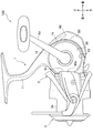
図1に示すように、主として、魚釣用スピニングリール100は、リール本体1と、リール本体1の前側に回転可能に設けられたロータ2と、ロータ2の回転運動と同期して前後方向移動可能に設けられたスプール3と、を備える。
(First embodiment)
As shown in FIG. 1, a fishing spinning reel 100 mainly moves in the front-rear direction in synchronization with the reel body 1, the rotor 2 rotatably provided on the front side of the reel body 1, and the rotational movement of the rotor 2. And a spool 3 provided in a possible manner.

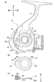
図2に示すように、リール本体1は、側面視で外形が略円形状に形成されたボディ10と、ボディ10の上部に一体形成され図示しない釣竿に装着される脚部11(図1参照)と、ボディ10の前側に設けられた筒状のボディ前部12と、を備える。ボディ10の左側部には、側部開口部13が形成されている。側部開口部13には、蓋部材30が取り付けられている。側部開口部13および蓋部材30は、側面視で円形に形成されている。
ボディ10の後部には、シール部材50を介して保護カバー40が装着されている。
なお、図2では蓋部材30の側面形状を簡略化している。
As shown in FIG. 2, the reel body 1 includes a body 10 whose outer shape is formed in a substantially circular shape in a side view, and a leg portion 11 that is integrally formed on the upper portion of the body 10 and is attached to a fishing rod (not shown). And a cylindrical body front portion 12 provided on the front side of the body 10. A side opening 13 is formed on the left side of the body 10. A lid member 30 is attached to the side opening 13. The side opening 13 and the lid member 30 are circular in a side view.
A protective cover 40 is attached to the rear portion of the body 10 via a seal member 50.
In FIG. 2, the side shape of the lid member 30 is simplified.

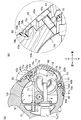
図3に示すように、ボディ10には、側部開口部13を開口として有底略円筒状の壁で囲まれた収容空間S1が形成されている(図4参照)。収容空間S1には、駆動軸筒7の後部、駆動軸筒7に挿通されるスプール軸8の後部、およびスプール軸8(スプール3、図1参照)を前後往復動させるためのスプール往復動装置70が配置されている。駆動軸筒7およびスプール軸8は、ボディ前部12の前方へ延出している。駆動軸筒7の後部には、ピニオンギヤ7aが形成されている。スプール軸8の後部は、ピニオンギヤ7a(駆動軸筒7)の後端よりも後方に延出している。
ここで、収容空間S1は、少なくともボディ10の内周壁10f(図8(a)参照)で仕切られている。
As shown in FIG. 3, the body 10 is formed with a housing space S1 surrounded by a substantially cylindrical wall with a bottom opening 13 as an opening (see FIG. 4). In the accommodation space S1, a rear portion of the drive shaft cylinder 7, a rear portion of the spool shaft 8 inserted through the drive shaft cylinder 7, and a spool reciprocating device for reciprocating the spool shaft 8 (spool 3, see FIG. 1). 70 is arranged. The drive shaft cylinder 7 and the spool shaft 8 extend forward of the front body portion 12. A pinion gear 7 a is formed at the rear portion of the drive shaft cylinder 7. The rear portion of the spool shaft 8 extends rearward from the rear end of the pinion gear 7a (drive shaft cylinder 7).
Here, the accommodation space S1 is partitioned by at least the inner peripheral wall 10f of the body 10 (see FIG. 8A).

スプール往復動装置70は、前後方向に延びるガイド軸71と、右側面に案内溝73が形成されてガイド軸71に沿って移動する摺動子72と、案内溝73に係合する偏芯突部75が形成された連動歯車74(構成部材)とを備える。スプール軸8の後端には、後方に突出して摺動子72に連結する連結部8a(図4参照)が設けられ、スプール軸8と摺動子72とが一体になっている。   The spool reciprocating device 70 includes a guide shaft 71 extending in the front-rear direction, a slider 72 having a guide groove 73 formed on the right side and moving along the guide shaft 71, and an eccentric protrusion engaging with the guide groove 73. The interlocking gear 74 (component member) in which the part 75 was formed is provided. A connecting portion 8a (see FIG. 4) that protrudes rearward and connects to the slider 72 is provided at the rear end of the spool shaft 8, and the spool shaft 8 and the slider 72 are integrated.

図4に示すように、ボディ10内には、左右方向に延在するハンドル軸5が設けられている。ハンドル軸5は、軸受5a,5bを介してボディ10と蓋部材30とに回転可能に支持されている。ハンドル軸5には機能部材としてのドライブギャ6および軸筒(歯車)6aが固定されている。ハンドル軸5の左端部には、連結軸5cを介してハンドル5d(図1参照)が取り付けられている。
ドライブギャ6は、ハンドル軸5の左側に固定されているとともに、前側でピニオンギヤ7aに噛合している。軸筒6aは、ハンドル軸5の右側に固定されているとともに、後側で連動歯車74に噛合している。
このため、ハンドル5dの巻き取り操作が行われると、巻き取り操作による駆動力がハンドル軸5、ドライブギャ6、ピニオンギャ7aを介して駆動軸筒7に伝達し、駆動軸筒7とともにロータ2が回転する。また、これとともにスプール3がスプール軸8やスプール往復動装置70を介して前後往復動される。これにより、釣糸は、ロータ2(図1参照)の図示しない釣糸案内部を介してスプール3の巻回胴部3a(図1参照)に均等に巻回される。
As shown in FIG. 4, a handle shaft 5 extending in the left-right direction is provided in the body 10. The handle shaft 5 is rotatably supported by the body 10 and the lid member 30 via bearings 5a and 5b. A drive gear 6 and a shaft cylinder (gear) 6a as functional members are fixed to the handle shaft 5. A handle 5d (see FIG. 1) is attached to the left end portion of the handle shaft 5 via a connecting shaft 5c.
The drive gear 6 is fixed to the left side of the handle shaft 5 and meshes with the pinion gear 7a on the front side. The shaft cylinder 6a is fixed to the right side of the handle shaft 5 and meshes with the interlocking gear 74 on the rear side.
For this reason, when the winding operation of the handle 5d is performed, the driving force by the winding operation is transmitted to the driving shaft cylinder 7 via the handle shaft 5, the drive gear 6, and the pinion gear 7a, and the rotor 2 together with the driving shaft cylinder 7 Rotate. At the same time, the spool 3 is reciprocated back and forth via the spool shaft 8 and the spool reciprocating device 70. As a result, the fishing line is evenly wound around the winding body 3a (see FIG. 1) of the spool 3 via a fishing line guide (not shown) of the rotor 2 (see FIG. 1).

次に、各部の構成について詳細に説明する。図4に示すように、側部開口部13は、円筒状の内周面13aを備えている。内周面13aは、ハンドル軸5の外周面と平行な面である。内周面13aの奥側には、図5(c)に示すように、雌ねじ13bが形成されている。側部開口部13の開口周縁部には、断面凹状の嵌合受部17が周方向に亘って形成されている。嵌合受部17は、底面部17aと、この底面部17aから断面アール状に立ち上がる立上り部17bと、を備えている。   Next, the configuration of each unit will be described in detail. As shown in FIG. 4, the side part opening part 13 is provided with the cylindrical internal peripheral surface 13a. The inner peripheral surface 13 a is a surface parallel to the outer peripheral surface of the handle shaft 5. As shown in FIG. 5C, a female screw 13b is formed on the inner side of the inner peripheral surface 13a. A fitting receiving portion 17 having a concave cross section is formed in the peripheral edge of the opening of the side opening 13 over the circumferential direction. The fitting receiving portion 17 includes a bottom surface portion 17a and a rising portion 17b that rises from the bottom surface portion 17a in a rounded cross section.

側部開口部13の内径は、図3,図4に示すように、ドライブギャ6の外径よりも大きく形成されている。これにより、ハンドル軸5、ドライブギャ6および軸筒6aは、側部開口部13を通じて収容空間S1内に挿入され、ボディ10に組み付けられる。別言すれば、側部開口部13は、円形で大径のドライブギャ6を挿通可能な相似形の大きな内径に形成されている。   The inner diameter of the side opening 13 is formed larger than the outer diameter of the drive gear 6 as shown in FIGS. Thus, the handle shaft 5, the drive gear 6, and the shaft cylinder 6 a are inserted into the accommodation space S <b> 1 through the side opening 13 and assembled to the body 10. In other words, the side opening 13 is formed to have a large inner diameter with a similar shape that can be inserted through the circular drive gear 6 having a large diameter.

このような側部開口部13は、ボディ10と同芯円状に形成されている。これによって、釣糸巻き取り時等にボディ10に生じる応力をボディ10の周方向に好適に分散することができるので、ボディ10の耐久性の向上ひいてはリール本体1の耐久性の向上を図ることができる。   Such a side opening 13 is formed concentrically with the body 10. As a result, the stress generated in the body 10 at the time of winding the fishing line can be suitably dispersed in the circumferential direction of the body 10, so that the durability of the body 10 and the durability of the reel body 1 can be improved. it can.

収容空間S1内には、図3に示すように、支持リブ19が形成されている。支持リブ19は収容空間S1の底部となるボディ10の右側部の内面10gに突設されている。支持リブ19には上部支持部19a,下部支持部19bが一体に設けられている。上部支持部19aは後方へ向けて開口する有底円筒状を呈している。上部支持部19aには、スプール往復動装置70のガイド軸71の前端部が支持されている。下部支持部19bは前後方向へ貫通する円筒状を呈しており、軸受部として機能している。下部支持部19bには、駆動軸筒7の後端部が支持されている。   As shown in FIG. 3, support ribs 19 are formed in the accommodation space S1. The support rib 19 protrudes from the inner surface 10g of the right side portion of the body 10 serving as the bottom of the accommodation space S1. The support rib 19 is integrally provided with an upper support portion 19a and a lower support portion 19b. The upper support portion 19a has a bottomed cylindrical shape that opens rearward. A front end portion of a guide shaft 71 of the spool reciprocating device 70 is supported on the upper support portion 19a. The lower support portion 19b has a cylindrical shape penetrating in the front-rear direction, and functions as a bearing portion. A rear end portion of the drive shaft cylinder 7 is supported by the lower support portion 19b.

蓋部材30は、図2に示すように、側部開口部13に取り付けられ、側部開口部13を液密に閉塞するとともに、ハンドル軸5の端側を支持する役割をなす。蓋部材30は、図5(b)に示すように、断面が山形状を呈しており、周壁部31と、周壁部31の中央部に一体的に設けられた円筒部32と、周壁部31の外周縁部に設けられた円筒状の挿入部33と、を備えている。 The lid member 30, as shown in FIG. 2, attached to the side opening 13, while closing the side opening 13 in a liquid tight manner, forms a role of supporting the left end of the handle shaft 5. As shown in FIG. 5B, the lid member 30 has a mountain shape in cross section, a peripheral wall portion 31, a cylindrical portion 32 integrally provided at the center of the peripheral wall portion 31, and the peripheral wall portion 31. The cylindrical insertion part 33 provided in the outer peripheral edge part of the.

周壁部31の外側面(側面)および内周面(側面)には、肉抜き部31bが形成されている。これにより蓋部材30の軽量化が図られている。円筒部32は、奥側となる側部が段状に拡径しており、この拡径した部分に軸受5a(図4参照)が収容されている。蓋部材30は、軸受5aを介してハンドル軸5の左端側を支持している。
なお、図4に示すように、ハンドル軸5の右端側は、軸受5bを介してボディ10に設けられたハンドル支持部10eに支持されている。
The outer surface of the peripheral wall 31 (left side) and the inner peripheral surface (the right side), the hollow portions 31b are formed. Thereby, weight reduction of the cover member 30 is achieved. Cylindrical portion 32, the right side as the rear side has a larger diameter stepped bearing 5a (see FIG. 4) is housed in the enlarged diameter portion. The lid member 30 supports the left end side of the handle shaft 5 via the bearing 5a.
As shown in FIG. 4, the right end side of the handle shaft 5 is supported by a handle support portion 10e provided on the body 10 via a bearing 5b.

挿入部33は、側部開口部13に向けて延在し、側部開口部13に挿入される部位である。挿入部の先端(右端)の外周部には、図5(c)に示すように、雄ねじ33aが形成されている。雄ねじ33aは、側部開口部13の雌ねじ13bに螺合可能である。これにより、側部開口部13に対して蓋部材30自体を螺合によって締結固定することができるので、蓋部材30の組み付けが行い易い。   The insertion portion 33 is a portion that extends toward the side opening 13 and is inserted into the side opening 13. As shown in FIG. 5C, a male screw 33a is formed on the outer peripheral portion of the distal end (right end) of the insertion portion. The male screw 33 a can be screwed into the female screw 13 b of the side opening 13. As a result, the lid member 30 itself can be fastened and fixed to the side opening 13 by screwing, so that the lid member 30 can be easily assembled.

雄ねじ33aよりも基端側となる挿入部33の外周部には、側部開口部13の内周面13aに当接する円筒状の当接面(当接部)33bが形成されている。当接面33bは、側部開口部13に蓋部材30を螺合により取り付けた際に、側部開口部13の内周面13aに対して周方向に当接して調芯作用をなす。これにより、側部開口部13と蓋部材30との同芯度が得られる。したがって、加工精度を高めなくても側部開口部13と蓋部材30との間に隙間が形成され難い。また、蓋部材30の中心とボディ10の中心とが一致するので、ハンドル軸5の傾倒が防止され、ハンドル5dの回転操作性および噛合性能が安定向上する。
なお、当接面33bは、側部開口部13の内周面13aに対して周方向に間隔を空けて部分的に当接するように構成してもよい。
A cylindrical contact surface (contact portion) 33b that contacts the inner peripheral surface 13a of the side opening 13 is formed on the outer peripheral portion of the insertion portion 33 that is on the proximal end side with respect to the male screw 33a. When the lid member 30 is attached to the side opening 13 by screwing, the abutting surface 33b abuts on the inner peripheral surface 13a of the side opening 13 in the circumferential direction and performs a centering action. Thereby, the concentricity of the side opening 13 and the lid member 30 is obtained. Therefore, it is difficult to form a gap between the side opening 13 and the lid member 30 without increasing the processing accuracy. Further, since the center of the lid member 30 and the center of the body 10 coincide with each other, the handle shaft 5 is prevented from being tilted, and the rotational operability and the meshing performance of the handle 5d are stably improved.
The abutting surface 33b may be configured to partially abut on the inner peripheral surface 13a of the side opening 13 at an interval in the circumferential direction.

挿入部33の外周面には、雄ねじ部33aと当接面33bとの間に収容凹部33cが形成されている。収容凹部33cには、シール材としてOリング33dが外嵌されている。   On the outer peripheral surface of the insertion portion 33, an accommodation recess 33c is formed between the male screw portion 33a and the contact surface 33b. An O-ring 33d is fitted on the housing recess 33c as a sealing material.

蓋部材30の外周縁部には、周方向外側に延在するフランジ状の嵌合部37が形成されている。嵌合部37は、側部開口部13の嵌合受部17の立上り部17bとの間に僅かな隙間(図示では隙間を有しているが接触嵌合も可能)を有した状態で底面部17aに当接し、嵌合受部17に対してインロー嵌合する。このようなインロー嵌合によって、組込基準面が外部に露出することがない。したがって、組込基準面に隙間が形成されたとしても、インロー嵌合部が防塵防水部として機能し、例えば、海水や水、あるいはこれらに混じった砂、異物等が侵入するのを遮ることができる。つまり、インロー嵌合部によって釣糸や海水、異物等の侵入防止が実現される。
また、インロー嵌合によって、嵌合部37の側方への突出量が抑えられている。これにより、リール操作時等に釣糸が解れた場合にも、解れた釣糸が蓋部材30の外周縁部に引っ掛かり難くなっている。
A flange-like fitting portion 37 extending outward in the circumferential direction is formed on the outer peripheral edge portion of the lid member 30. The fitting portion 37 is a bottom surface in a state where there is a slight gap (in the drawing, there is a gap but contact fitting is possible) between the side opening 13 and the rising portion 17b of the fitting receiving portion 17. It abuts on the portion 17 a and is inlay-fitted to the fitting receiving portion 17. By such inlay fitting, the built-in reference surface is not exposed to the outside. Therefore, even if a gap is formed on the built-in reference surface, the spigot fitting portion functions as a dustproof and waterproof portion, and for example, seawater, water, sand mixed in them, foreign matter, etc. can be prevented from entering. it can. That is, the inlay fitting portion can prevent intrusion of fishing line, seawater, foreign matter and the like.
Moreover, the protrusion amount to the side of the fitting part 37 is suppressed by inlay fitting. Thereby, even when the fishing line is unwound at the time of reel operation or the like, the unraveled fishing line is not easily caught on the outer peripheral edge portion of the lid member 30.

なお、図5(c)に示すように、蓋部材30の外周縁部の外面30gと、側部開口部13の外周縁部の外面13gとは、嵌合部37(嵌合受部17)を挟んで略連続する傾斜面とされている。これによって、解れた釣糸がより引っ掛かり難い構成となっている。   In addition, as shown in FIG.5 (c), the outer surface 30g of the outer peripheral part of the cover member 30 and the outer surface 13g of the outer peripheral part of the side part opening part 13 are the fitting parts 37 (fitting receiving part 17). It is made into the inclined surface which continues substantially on both sides. As a result, the undissolved fishing line is less likely to be caught.

図5(c)に示すように、嵌合部37と当接面33bとの間には、断面湾曲凹状の小径部38が形成されている。小径部38には、グリスやオイル等の潤滑剤が塗布されている。潤滑剤によって、蓋部材30のスムーズな取り付けが可能になるとともに、側部開口部13の内周面13aとのシール性が高められている。
なお、同様に、嵌合受部17や嵌合部37に対してグリスやオイル等の潤滑剤を塗布してもよい。
As shown in FIG. 5C, a small-diameter portion 38 having a concave cross-sectional shape is formed between the fitting portion 37 and the contact surface 33b. A lubricant such as grease or oil is applied to the small diameter portion 38. The lubricant enables smooth attachment of the lid member 30 and enhances the sealing performance with the inner peripheral surface 13a of the side opening 13.
Similarly, a lubricant such as grease or oil may be applied to the fitting receiving portion 17 and the fitting portion 37.

ボディ10とボディ前部12との境界部には、図2,3に示すように、薄板状を呈するフランジ部16が設けられている。フランジ部16の左側部には、図2に示すように、凹状部16bが形成されている。凹状部16bは、蓋部材30の前端部30eの形状に沿って前方へ向けて凹設されている。これにより、蓋部材30の前端部30eは、フランジ部16の上部後面16aよりも前方に入り込むように位置している。また、蓋部材30の前端部30eは、図1に示すように、ロータ2との位置関係において、ロータ2の最後端部2aよりも前方に位置している。さらに、蓋部材30の前端部30eは、図2に示すように、ボディ前部12を覆う有底円筒状のカバー12aとの位置関係において、カバー12aの後端部12bよりも前方に位置している。このような位置関係に蓋部材30の前端部30eが位置することによって、ボディ10の前後方向のコンパクト化を図りつつ、蓋部材30の大径化が可能となっている。なお、凹状部16bは、蓋部材30を取り付ける際の逃げ部となる。   As shown in FIGS. 2 and 3, a flange portion 16 having a thin plate shape is provided at a boundary portion between the body 10 and the body front portion 12. A concave portion 16b is formed on the left side of the flange portion 16 as shown in FIG. The recessed portion 16b is recessed forward along the shape of the front end portion 30e of the lid member 30. As a result, the front end portion 30 e of the lid member 30 is positioned so as to enter further forward than the upper rear surface 16 a of the flange portion 16. Further, the front end portion 30 e of the lid member 30 is located in front of the rearmost end portion 2 a of the rotor 2 in the positional relationship with the rotor 2 as shown in FIG. 1. Further, as shown in FIG. 2, the front end portion 30 e of the lid member 30 is positioned forward of the rear end portion 12 b of the cover 12 a in the positional relationship with the bottomed cylindrical cover 12 a that covers the front body portion 12. ing. By positioning the front end portion 30e of the lid member 30 in such a positional relationship, the diameter of the lid member 30 can be increased while the body 10 is made compact in the front-rear direction. The concave portion 16b serves as an escape portion when the lid member 30 is attached.

ボディ10の左側部の後部には、図2,3に示すように、側部開口部13(蓋部材30)に沿うようにしてボディ10の上部から下部に亘る湾曲状の架橋部14が形成されている。架橋部14の外形状は、側部開口部13(蓋部材30)と同芯円状に形成されている。架橋部14は、図3に示すように、側部開口部13の開口縁部の一部を構成している。
なお、架橋部14は、側部開口部13と同芯円状に形成されたものを示したが、これに限られることはなく、側部開口部13の中心(ハンドル軸5の中心)に対して前側または後側に偏芯したものであってもよい。また、架橋部14は、側面視で外形状が直線状部分を含むものであってもよい。
As shown in FIGS. 2 and 3, a curved bridging portion 14 extending from the upper portion to the lower portion of the body 10 is formed at the rear portion of the left side portion of the body 10 along the side opening portion 13 (lid member 30). Has been. The outer shape of the bridging portion 14 is formed concentrically with the side opening 13 (lid member 30). As shown in FIG. 3, the bridging portion 14 constitutes a part of the opening edge of the side opening 13.
In addition, although the bridge | bridging part 14 showed what was formed concentric with the side part opening part 13, it is not restricted to this, The center (center of the handle shaft 5) of the side part opening part 13 is not restricted to this. On the other hand, it may be eccentric to the front side or the rear side. Moreover, the bridge | crosslinking part 14 may contain a linear part in an external shape by side view.

ボディ10の後部には、図6(a)に示すように、開口部として後部開口部15が形成されている。後部開口部15は収容空間S1に連通している。後部開口部15の周縁部には、後方へ向けて突出する縁リブ15aが形成されている。本実施形態では、図3に示すように、後部開口部15を通じてスプール往復動装置70の連動歯車74の一部、ストローク位置が最後端位置にあるときの摺動子72の一部、およびガイド軸71の後端部71aが、ボディ10の後部から後方へ突出している。つまり、後部開口部15は、これらの部材が挿通配置される大きさおよび形状を備えている。なお、これらの部材が後部開口部15を通じてボディ10の後方に突出するので、その分、収容空間S1は、コンパクトな大きさに形成されている。
また、リール本体1(ボディ10)の後部の後方に配置することができるので、リール本体1(ボディ10)の小型化を図ることができる。また、リール本体1(ボディ10)の後部の後方のスペースを有効利用してスプール往復動装置70の前後ストロークを好適に確保することができる。
As shown in FIG. 6A, a rear opening 15 is formed at the rear of the body 10 as an opening. The rear opening 15 communicates with the accommodation space S1. An edge rib 15 a that protrudes rearward is formed on the peripheral edge of the rear opening 15. In the present embodiment, as shown in FIG. 3, a part of the interlocking gear 74 of the spool reciprocating device 70 through the rear opening 15, a part of the slider 72 when the stroke position is at the rearmost position, and a guide A rear end portion 71 a of the shaft 71 protrudes rearward from the rear portion of the body 10. That is, the rear opening 15 has a size and a shape in which these members are inserted and arranged. In addition, since these members protrude rearward of the body 10 through the rear opening 15, the accommodation space S1 is formed in a compact size.
Moreover, since it can arrange | position behind the rear part of the reel main body 1 (body 10), size reduction of the reel main body 1 (body 10) can be achieved. In addition, the front and rear stroke of the spool reciprocating device 70 can be suitably secured by effectively utilizing the space behind the rear portion of the reel body 1 (body 10).

後部開口部15の周りには、図6(a)に示すように、カバー装着部18が形成されている。カバー装着部18には、シール部材50を介して保護カバー40が取り付けられている(図6(b)参照)。保護カバー40の内側には、図4に示すように、空間部S2が形成されている。空間部S2には、前記したように、ボディ10の後部から突出した連動歯車74の一部および摺動子72の一部が収容される。つまり、連動歯車74の一部および摺動子72の一部は、シール部材50を介して装着される保護カバー40で覆われて液密に収容されている(図3参照)。ボディ10の後部から突出するガイド軸71の後端部71aは、図3,図7(a)に示すように、保護カバー40の内側に設けられる支持部43cに支持されている。
スプール軸8およびスプール往復動装置70の各部材は、後記するように、後部開口部15を通じてリール本体1の後方から組み付けられる。
A cover mounting portion 18 is formed around the rear opening 15 as shown in FIG. A protective cover 40 is attached to the cover mounting portion 18 via a seal member 50 (see FIG. 6B). As shown in FIG. 4, a space S <b> 2 is formed inside the protective cover 40. As described above, a part of the interlocking gear 74 protruding from the rear part of the body 10 and a part of the slider 72 are accommodated in the space S2. That is, a part of the interlocking gear 74 and a part of the slider 72 are covered with the protective cover 40 attached via the seal member 50 and are stored in a liquid-tight manner (see FIG. 3). The rear end portion 71a of the guide shaft 71 protruding from the rear portion of the body 10 is supported by a support portion 43c provided inside the protective cover 40, as shown in FIGS.
Each member of the spool shaft 8 and the spool reciprocating device 70 is assembled from the rear side of the reel body 1 through the rear opening 15 as described later.

ボディ10の右側部には、図4に示すように、取付部20が凹設されている。取付部20は、図7(a)に示すように、側面視でカム形状を呈しており、ボディ10の左側部に設けられた円筒状のハンドル支持部10e(図4参照)の周りに形成されている。取付部20には、同じくカム形状に形成された支持部材21が取り付けられている。   As shown in FIG. 4, a mounting portion 20 is recessed in the right side portion of the body 10. As shown in FIG. 7A, the mounting portion 20 has a cam shape in a side view, and is formed around a cylindrical handle support portion 10e (see FIG. 4) provided on the left side portion of the body 10. Has been. A support member 21 that is also formed in a cam shape is attached to the attachment portion 20.

支持部材21は、図7(b)(c)に示すように、板状を呈している。支持部材21は、外周部22aが厚肉に形成され、内周部22bが薄肉に形成されている。外周部22aの先端左側面には、左側方へ突出するボス部23が形成されている。ボス部23は、図4に示すように、取付部20に形成された挿入孔20aを通じて収容空間S1に突出している。ボス部23には、軸受23bを介して連動歯車74が支持されており、ボス部23は、連動歯車74の支軸として機能している。つまり、連動歯車74は、ボディ10に対して直接支持されることなく、ボディ10に取り付けられる支持部材21によって支持されるように構成されている。したがって、ボディ10は、その右側部の内面に、連動歯車74を支持するためのボス部を形成する必要のない構造となっている。   As shown in FIGS. 7B and 7C, the support member 21 has a plate shape. The support member 21 has an outer peripheral portion 22a formed thick and an inner peripheral portion 22b formed thin. A boss 23 that protrudes to the left is formed on the left side of the distal end of the outer peripheral portion 22a. As shown in FIG. 4, the boss portion 23 protrudes into the accommodation space S <b> 1 through the insertion hole 20 a formed in the attachment portion 20. An interlocking gear 74 is supported on the boss portion 23 via a bearing 23 b, and the boss portion 23 functions as a support shaft of the interlocking gear 74. That is, the interlocking gear 74 is configured to be supported by the support member 21 attached to the body 10 without being directly supported by the body 10. Therefore, the body 10 has a structure in which it is not necessary to form a boss part for supporting the interlocking gear 74 on the inner surface of the right side part.

これによって、収容空間S1の底面を構成しているボディ10の右側部の内面を略平らに形成することができ、スプール軸8やスプール往復動装置70の各部材を後部開口部15を通じてスムーズに組み付けることができる。   As a result, the inner surface of the right side portion of the body 10 constituting the bottom surface of the housing space S1 can be formed substantially flat, and each member of the spool shaft 8 and the spool reciprocating device 70 can be smoothly passed through the rear opening 15. Can be assembled.

軸受23bは、図4に示すように、内輪の右端がボス部23の段部に当て付けられており、外輪の右端が連動歯車74の段部に当て付けられている。また、軸受23bは、内輪の左端がねじ穴23aに螺合される止めねじ23cで抜け止めされている。   As shown in FIG. 4, in the bearing 23 b, the right end of the inner ring is applied to the step portion of the boss portion 23, and the right end of the outer ring is applied to the step portion of the interlocking gear 74. Further, the bearing 23b is prevented from coming off by a set screw 23c in which the left end of the inner ring is screwed into the screw hole 23a.

取付部20における挿入孔20aの周縁部には、防塵防水用としてOリング23d(図7(a)に破線で図示)が配置されている。   An O-ring 23d (shown by a broken line in FIG. 7A) is disposed on the periphery of the insertion hole 20a in the mounting portion 20 for dustproofing and waterproofing.

支持部材21のボス部23の近傍には、図7(b)(c)に示すように、突部26が設けられている。突部26は、取付部20に向けて突出しており、取付部20に設けられた位置決め穴20c(図7(a)参照)に係止される。突部26は、取付部20に対する支持部材21の位置決め用部材として機能する。   As shown in FIGS. 7B and 7C, a protrusion 26 is provided in the vicinity of the boss 23 of the support member 21. The protrusion 26 protrudes toward the attachment portion 20 and is locked in a positioning hole 20c (see FIG. 7A) provided in the attachment portion 20. The protrusion 26 functions as a member for positioning the support member 21 with respect to the attachment portion 20.

支持部材21の内周部22bは、図7(b)に示すように、円形帯状に形成されている。内周部22bは、図4に示すように、ボディ10のハンドル支持部10eを囲んでいる。内周部22bの右側面には、図4に示すように、固定部材24の環状部24aが当接している。
固定部材24は、支持部材21を抜け止め固定する部材であり、ボディ10のハンドル支持部10eに螺合により取り付けられている。固定部材24を締め付けることで、環状部24aが支持部材21の内周部22bに当接し、支持部材21が取付部20に固定される。固定部材24の先端部24bには、螺合によりハンドルキャップ25が取り付けられている。
As shown in FIG. 7B, the inner peripheral portion 22b of the support member 21 is formed in a circular belt shape. As shown in FIG. 4, the inner peripheral portion 22 b surrounds the handle support portion 10 e of the body 10. As shown in FIG. 4, the annular portion 24a of the fixing member 24 is in contact with the right side surface of the inner peripheral portion 22b.
The fixing member 24 is a member that prevents and fixes the support member 21, and is attached to the handle support portion 10 e of the body 10 by screwing. By tightening the fixing member 24, the annular portion 24 a comes into contact with the inner peripheral portion 22 b of the support member 21, and the support member 21 is fixed to the attachment portion 20. A handle cap 25 is attached to the distal end portion 24b of the fixing member 24 by screwing.

支持部材21を取付部20に取り付けることによって、連動歯車74を支持する位置(ボス部23の位置)が決まり、ハンドル軸5と連動歯車74の軸との軸間距離が決定する。これにより、前記軸間距離が異なる距離となるように支持部材21の仕様を変更することによって、異なる径(異なる仕様)の連動歯車74を支持することができ、ストローク量を変更することが可能となる。したがって、魚釣用スピニングリール100の仕様変更を低コストで容易に行うことができる。この場合、異なる仕様の支持部材21を取付可能とするために、取付部20の挿入孔20aの形状を、例えば、大径の円形状に形成したり、長穴形状に形成したりしてもよい。   By attaching the support member 21 to the attachment portion 20, the position where the interlocking gear 74 is supported (the position of the boss portion 23) is determined, and the inter-axis distance between the handle shaft 5 and the axis of the interlocking gear 74 is determined. Thereby, by changing the specification of the support member 21 so that the distance between the shafts is different, the interlocking gear 74 having a different diameter (different specification) can be supported, and the stroke amount can be changed. It becomes. Therefore, the specification change of the fishing spinning reel 100 can be easily performed at low cost. In this case, in order to make it possible to attach the support member 21 having a different specification, the shape of the insertion hole 20a of the attachment portion 20 may be formed into a large-diameter circular shape or a long hole shape, for example. Good.

なお、支持部材21によって仕様変更が可能となるので、リール本体1の共有化も可能となる。したがって、リール本体1を製造する際の金型をリールの仕様毎に数種類用意する必要がなくなり、仕様変更に伴うコストの低減を図ることができる。また、リールの大きさの枠を超えた部品の共通化も可能となる。これにより、リール価格上昇の抑制を図ることも可能である。   Since the specification can be changed by the support member 21, the reel body 1 can be shared. Accordingly, it is not necessary to prepare several types of molds for manufacturing the reel body 1 for each reel specification, and the cost associated with the specification change can be reduced. It is also possible to share parts that exceed the reel size frame. Thereby, it is also possible to suppress an increase in reel price.

また、ボディ10にボスを形成する必要がないので、架橋部14とボス部23とが側面視で重なるレイアウトのような加工に困難性を有する構造であっても、容易に実現することができる。   In addition, since it is not necessary to form a boss on the body 10, even a structure having difficulty in processing such as a layout in which the bridging portion 14 and the boss portion 23 overlap in a side view can be easily realized. .

スプール往復動装置70の摺動子72は、ストロークの最後端位置にある場合に、図8(a)に示すように、ボディ10の後部(架橋部14で仕切られる部位)から後方へ突出する。また、摺動子72のハンドル軸5の対向部には凹部72aが形成されており、ストロークの最前端位置にある場合に、ハンドル軸5の中心O1を上下方向に凹部72aで受け入れて跨ぐように位置する。このとき、スプール軸8の後端部は、ハンドル軸5の中心O1よりも前方に位置する。これにより、スプール軸8のストローク量が確保されている。   When the slider 72 of the spool reciprocating device 70 is located at the end position of the stroke, as shown in FIG. 8A, the slider 72 projects rearward from the rear portion (part partitioned by the bridging portion 14) of the body 10. . Further, a concave portion 72a is formed in the opposite portion of the slider 72 to the handle shaft 5 so that the center O1 of the handle shaft 5 is received by the concave portion 72a in the vertical direction when it is at the foremost position of the stroke. Located in. At this time, the rear end portion of the spool shaft 8 is located in front of the center O1 of the handle shaft 5. Thereby, the stroke amount of the spool shaft 8 is secured.

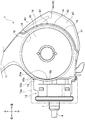
保護カバー40は、図2,図4に示すように、ボディ10の後部に設けられたカバー装着部18にシール部材50を介して着脱可能に取り付けられる。
保護カバー40は、図2に示すように、側面視で略三日月形に形成されている。保護カバー40は、図6(b)に示すように、後面視でスプール軸8(図3参照)を通る中心線O2を基準として、中心線O2の左側よりも右側が幅広な形状に形成されている。保護カバー40は、図4に示すように、横断面が凹状に形成されており、ボディ10の収容空間S1に連通する空間部S2を形成している。空間部S2は、保護カバー40の内側の上下方向の略全体に亘って形成されている。保護カバー40は、図8(a)に示すように、その上端部および下端部に設けられたねじ孔40a,40bに挿通した固定ねじ40cを、カバー装着部18の上部ボス部10cおよび下部ボス部10dに締め付けることによってカバー装着部18に取り付けられる。
As shown in FIGS. 2 and 4, the protective cover 40 is detachably attached to a cover mounting portion 18 provided at the rear portion of the body 10 via a seal member 50.
As shown in FIG. 2, the protective cover 40 is formed in a substantially crescent shape when viewed from the side. As shown in FIG. 6B, the protective cover 40 is formed in a shape that is wider on the right side than the left side of the center line O2 with respect to the center line O2 passing through the spool shaft 8 (see FIG. 3) in rear view. ing. As shown in FIG. 4, the protective cover 40 has a concave cross section and forms a space S <b> 2 that communicates with the housing space S <b> 1 of the body 10. The space S2 is formed over substantially the entire vertical direction inside the protective cover 40. As shown in FIG. 8 (a), the protective cover 40 has a fixing screw 40c inserted through screw holes 40a and 40b provided at the upper and lower ends thereof, and the upper boss portion 10c and the lower boss of the cover mounting portion 18. The cover is attached to the cover mounting portion 18 by being fastened to the portion 10d.

次に、ボディ10に対するスプール軸8およびスプール往復動装置70の組み付け手順について説明する。組み付けにあたって、はじめに、後部開口部15を通じてスプール往復動装置70のガイド軸71を収容空間S1に挿入し、ガイド軸71の先端部を上部支持部19aに差し込む。この状態でガイド軸71の後端部71aは、後部開口部15を通じて、ボディ10の後部から後方に突出する。   Next, a procedure for assembling the spool shaft 8 and the spool reciprocating device 70 with respect to the body 10 will be described. In assembling, first, the guide shaft 71 of the spool reciprocating device 70 is inserted into the accommodation space S1 through the rear opening 15, and the tip of the guide shaft 71 is inserted into the upper support portion 19a. In this state, the rear end portion 71 a of the guide shaft 71 projects rearward from the rear portion of the body 10 through the rear opening 15.

続いて、スプール軸8の後端の連結部8a(図4参照)に、図示しないねじを用いて摺動子72を連結する。そして、摺動子72に連動歯車74を近づけ、連動歯車74の偏芯突部75を摺動子72の案内溝73に係合させた状態にして、スプール軸8とともに摺動子72および連動歯車74を後部開口部15を通じて収容空間S1に挿入する。なお、連動歯車74には予め軸受23bを装着しておく。   Subsequently, the slider 72 is connected to a connecting portion 8a (see FIG. 4) at the rear end of the spool shaft 8 using a screw (not shown). Then, the interlocking gear 74 is brought close to the slider 72 so that the eccentric protrusion 75 of the interlocking gear 74 is engaged with the guide groove 73 of the slider 72, and the slider 72 and the interlocking together with the spool shaft 8. The gear 74 is inserted into the accommodation space S <b> 1 through the rear opening 15. Note that the bearing 23b is attached to the interlocking gear 74 in advance.

その後、スプール軸8の先端部を駆動軸筒7の空洞部に挿入する。挿入する過程で、摺動子72が後部開口部15に近づいたら、ボディ10の後部から突出しているガイド軸71の後端部71aに摺動子72の図示しないガイド孔を合わせ、ガイド軸71に摺動子72を係合する。これにより摺動子72および連動歯車74はガイド軸71に沿って挿入される。   Thereafter, the tip of the spool shaft 8 is inserted into the hollow portion of the drive shaft cylinder 7. When the slider 72 approaches the rear opening 15 in the insertion process, a guide hole (not shown) of the slider 72 is aligned with the rear end portion 71 a of the guide shaft 71 protruding from the rear portion of the body 10. The slider 72 is engaged. As a result, the slider 72 and the interlocking gear 74 are inserted along the guide shaft 71.

その後、ボディ10の右側方からボディ10の取付部20に支持部材21を取り付け、挿入孔20aを通じてボス部23を収容空間S1内に突出させ、連動歯車74の軸受23bに挿通する。   Thereafter, the support member 21 is attached to the attachment portion 20 of the body 10 from the right side of the body 10, and the boss portion 23 protrudes into the accommodation space S1 through the insertion hole 20a and is inserted into the bearing 23b of the interlocking gear 74.

その後、軸受23bのねじ穴23aに止めねじ23cを螺合し、ボス部23に連動歯車74を抜け止め保持する。
以上により、後部開口部15を通じてスプール軸8およびスプール往復動装置70を収容空間S1に組み付けることができる。なお、上記組み付け順は一例を示すものであり、適宜状況に応じて変更可能である。
Thereafter, a set screw 23c is screwed into the screw hole 23a of the bearing 23b, and the interlocking gear 74 is retained and held in the boss portion 23.
As described above, the spool shaft 8 and the spool reciprocating device 70 can be assembled into the accommodation space S1 through the rear opening 15. Note that the above assembling order is an example, and can be appropriately changed according to the situation.

このように、後部開口部15を通じてスプール往復動装置70を容易に組み付けることができるので、生産性が向上する。このことは、コストの低減に寄与する。また、容易に組み付けることができるので、リール本体1における構成部材の配置の自由度が高まり、設計の自由度が増す。   In this way, the spool reciprocating device 70 can be easily assembled through the rear opening 15, so that productivity is improved. This contributes to cost reduction. Moreover, since it can be assembled easily, the degree of freedom of arrangement of the constituent members in the reel body 1 is increased, and the degree of freedom of design is increased.

さらに、支持部材21の仕様を変更することによって、ハンドル軸5と連動歯車74の軸との軸間距離を異なる距離に変更して外径の異なる連動歯車74を支持することができるので、スプール軸8のストローク長を容易に変更することができる。   Further, by changing the specification of the support member 21, the inter-axis distance between the handle shaft 5 and the shaft of the interlocking gear 74 can be changed to a different distance to support the interlocking gear 74 having a different outer diameter. The stroke length of the shaft 8 can be easily changed.

保護カバー40は、図2に示すように、ボディ10の後部下部に配置される基部41と、基部41の後端から後方斜め上方へ延在する後傾部42と、後傾部42の上端から後方斜め前方へ延在する前傾部43と、基部41と後傾部42と前傾部43とに亘って形成された左右両側部44,45(図2では左側部44のみ図示)と、を備えている。基部41、後傾部42および前傾部43の(外面)は、略平に形成されている。   As shown in FIG. 2, the protective cover 40 includes a base portion 41 disposed at the lower rear portion of the body 10, a rearward inclined portion 42 extending obliquely rearward and upward from the rear end of the base portion 41, and an upper end of the rearward inclined portion 42. Forwardly inclined portion 43 extending obliquely forward and rearward, and left and right side portions 44 and 45 (only the left side portion 44 is shown in FIG. 2) formed between the base portion 41, the backward inclined portion 42, and the forward inclined portion 43, It is equipped with. The (outer surface) of the base 41, the backward inclined portion 42, and the forward inclined portion 43 are formed substantially flat.

基部41の内側(上面)には、図9(a),図10(a)に示すように、基部ボス部41aが突出形成され、この基部ボス部41aにねじ孔40bが形成されている。基部ボス部41aは、カバー装着部18の下部ボス部10d(図6(b)参照)に当接される。ねじ孔40aの口縁には、基部ボス部41aに螺着される止めねじ40c(図8(a)参照)の頭部が当接され、止めねじ40cを締め付けることによって、基部41がカバー装着部18に固定される。ねじ孔40aの口縁部は、止めねじ40cの頭部が基部41の外面から突出しない深さに形成されている。
基部41の前端部41cは、図8(a)に示すように、カバー装着部18の下部後壁18aに対応する形状とされており、下部後壁18aに対してシール部材50を挟んで後方から当て付けられる。
As shown in FIGS. 9A and 10A, a base boss 41a is formed on the inner side (upper surface) of the base 41, and a screw hole 40b is formed in the base boss 41a. The base boss portion 41a is in contact with the lower boss portion 10d (see FIG. 6B) of the cover mounting portion 18. The head of a set screw 40c (see FIG. 8A) screwed to the base boss 41a is brought into contact with the lip of the screw hole 40a, and the base 41 is attached to the cover by tightening the set screw 40c. It is fixed to the part 18. The mouth edge portion of the screw hole 40 a is formed to a depth at which the head of the set screw 40 c does not protrude from the outer surface of the base portion 41.
As shown in FIG. 8A, the front end portion 41c of the base portion 41 has a shape corresponding to the lower rear wall 18a of the cover mounting portion 18, and is located behind the lower rear wall 18a with the seal member 50 interposed therebetween. It is guessed from.

後傾部42は、図8(a)に示すように、ボディ10の後部開口部15から突出するスプール往復動装置70の連動歯車74や摺動子72に対して接触することのない間隔を空けて配置されている。後傾部42の側方において、右側部45には、図10(b)に示すように、補強用リブ45aが形成されている。   As shown in FIG. 8A, the rearwardly inclined portion 42 has an interval that does not contact the interlocking gear 74 and the slider 72 of the spool reciprocating device 70 protruding from the rear opening 15 of the body 10. It is arranged in the space. As shown in FIG. 10B, reinforcing ribs 45 a are formed on the right side 45 on the side of the rearward inclined portion 42.

前傾部43は、ボディ10の後部上部を覆っている(図8(a)参照)。前傾部43の内側(前面)には、図9(a),図10(a)(b)に示すように、上部凹部43a、ねじ孔40aおよび支持部43cが形成されている。上部凹部43aは、図8(b)に示すように、カバー装着部18の上部突起部18cに対応して係止可能に凹設されている。上部凹部43aは、保護カバー40の上部の位置決め部として機能する。上部凹部43aの上端縁部には、シール部材50の上部の第六規制部59aが係止される。
前傾部43の上端部43dは、カバー装着部18の上部後壁18bに対応する形状とされており、上部後壁18bに対してシール部材50を挟んで後方から当て付けられる。
The forward inclined portion 43 covers the upper rear portion of the body 10 (see FIG. 8A). As shown in FIGS. 9A, 10A, and 10B, an upper concave portion 43a, a screw hole 40a, and a support portion 43c are formed on the inner side (front surface) of the forward inclined portion 43. As shown in FIG. 8B, the upper recessed portion 43 a is recessed so as to be able to be locked corresponding to the upper protruding portion 18 c of the cover mounting portion 18. The upper concave portion 43 a functions as a positioning portion on the upper portion of the protective cover 40. A sixth restricting portion 59a at the top of the seal member 50 is locked to the upper edge of the upper recess 43a.
The upper end portion 43d of the forward inclined portion 43 has a shape corresponding to the upper rear wall 18b of the cover mounting portion 18, and is applied from the rear to the upper rear wall 18b with the seal member 50 interposed therebetween.

ねじ孔40aは、図10(a)(b)に示すように、前傾部43の内側(前面)に突出形成された前傾部ボス部41eに形成されている。支持部43cは、図8(a)に示すように、ガイド軸71の後端部71aを支持する。   As shown in FIGS. 10A and 10B, the screw hole 40 a is formed in a forward inclined portion boss portion 41 e that is formed to protrude to the inside (front surface) of the forward inclined portion 43. The support portion 43c supports the rear end portion 71a of the guide shaft 71 as shown in FIG.

なお、保護カバー40をシール部材50を介してカバー装着部18に取り付ける際には、カバー装着部18の上部突起部18cに対して前傾部43の上部凹部43aを引っ掛けておいてから、上部凹部43aを中心として保護カバー40を下方へ回動させることで、カバー装着部18に対する保護カバー40の位置合わせを容易に行うことができる。   When the protective cover 40 is attached to the cover mounting portion 18 via the seal member 50, the upper concave portion 43a of the forward inclined portion 43 is hooked on the upper protrusion portion 18c of the cover mounting portion 18 and then the upper portion. By rotating the protective cover 40 downward about the recess 43a, the protective cover 40 can be easily aligned with the cover mounting portion 18.

保護カバー40の前縁部には、図10(c)(d)に示すように、前方へ向けて突出する突部としての突起部46が形成されている。突起部46は、図9(a)に示すように、前傾部43の上端部43dの前縁部、左右両側部44,45の前縁部、および基部41の前縁部に亘って環状に形成されている。突起部46は、図10(c)(d)に示すように、断面略三角形状の先細り形状とされており、対向するシール部材50の対向面に当接してシール部材50に対してめり込むようになっている。
なお、突起部46は、環状に形成されたものに限られることはなく、部分的な切れ目を有していてもよい。
As shown in FIGS. 10C and 10D, a protrusion 46 as a protrusion protruding forward is formed on the front edge of the protective cover 40. As shown in FIG. 9A, the protrusion 46 has an annular shape extending over the front edge of the upper end 43 d of the forward inclined portion 43, the front edge of the left and right side portions 44 and 45, and the front edge of the base 41. Is formed. As shown in FIGS. 10 (c) and 10 (d), the protrusion 46 has a tapered shape with a substantially triangular cross section, and is in contact with the opposing surface of the opposing seal member 50 so as to be recessed into the seal member 50. It has become.
In addition, the protrusion part 46 is not restricted to what was formed in cyclic | annular form, You may have a partial cut | interruption.

シール部材50は、図2に示すように、カバー装着部18と保護カバー40との間に挟着される部材である。シール部材50は、図11(a)(b),図12(a)(b)に示すように、後部開口部15の縁リブ15a(図6(b)参照)に沿う環状を呈しており、ボディ10の収容空間S1および保護カバー40の空間部S2を液密にシールしている(図13(a)参照)。   As shown in FIG. 2, the seal member 50 is a member that is sandwiched between the cover mounting portion 18 and the protective cover 40. As shown in FIGS. 11 (a), 11 (b), 12 (a), and 12 (b), the seal member 50 has an annular shape along the edge rib 15a of the rear opening 15 (see FIG. 6 (b)). The housing space S1 of the body 10 and the space S2 of the protective cover 40 are sealed in a liquid-tight manner (see FIG. 13A).

シール部材50は、図11(a)(b)に示すように、下縁部51と、上縁部52と、下縁部51と上縁部52とを繋ぐ左縁部54および右縁部55とを備えている。下縁部51の後面には、保護カバー40の基部41の前縁部が当接され、上縁部52の後面には、同じく前傾部43の前縁部が当接される。また、左縁部54の後面には、同じく左側部44の前縁部が当接され、右縁部55の後面には、同じく右側部45の前縁部が当接される。これにより、下縁部51、上縁部52、左縁部54、および右縁部55には、保護カバー40の各前縁部の突起部46がめり込む状態となる。   As shown in FIGS. 11A and 11B, the seal member 50 includes a lower edge 51, an upper edge 52, a left edge 54 and a right edge that connect the lower edge 51 and the upper edge 52. 55. The front edge of the base 41 of the protective cover 40 is in contact with the rear surface of the lower edge 51, and the front edge of the forward inclined portion 43 is also in contact with the rear surface of the upper edge 52. Similarly, the front edge of the left side 44 is in contact with the rear surface of the left edge 54, and the front edge of the right side 45 is also in contact with the rear surface of the right edge 55. As a result, the protrusions 46 at the front edge portions of the protective cover 40 are recessed into the lower edge portion 51, the upper edge portion 52, the left edge portion 54, and the right edge portion 55.

シール部材50の下部には、カバー装着部18の下部ボス部10d(図8(a)参照)が挿通される切れ込み部53が形成されている。切れ込み部53は、下縁部51と、左縁部54の下部幅広部54aと、右縁部55の下部幅広部55aと、で囲われて形成されている。
シール部材50の上部には、カバー装着部18の上部ボス部10c(図8(a)参照)が挿通される挿通部56が形成されている。挿通部56は、上縁部52と、左縁部54の上部幅広部54bと、右縁部55の上部幅広部55bと、左縁部54と右縁部55とを連結する連結部57と、で囲われて形成されている。
In the lower part of the seal member 50, a notch 53 is formed through which the lower boss part 10d (see FIG. 8A) of the cover mounting part 18 is inserted. The cut portion 53 is formed by being surrounded by the lower edge portion 51, the lower wide portion 54 a of the left edge portion 54, and the lower wide portion 55 a of the right edge portion 55.
An insertion portion 56 into which the upper boss portion 10c (see FIG. 8A) of the cover mounting portion 18 is inserted is formed on the upper portion of the seal member 50. The insertion portion 56 includes an upper edge portion 52, an upper wide portion 54 b of the left edge portion 54, an upper wide portion 55 b of the right edge portion 55, and a connecting portion 57 that connects the left edge portion 54 and the right edge portion 55. , Is enclosed and formed.

連結部57には、凹状の切欠部57dが形成されている。切欠部57d内には、スプール往復動装置70のガイド軸71の後端部71a(図8(a)参照)が挿通される。連結部57の前面は、図12(a)に示すように、左縁部54の前面および右縁部55の前面よりも後方に位置している。これにより連結部57の左右側方には、段差状の第一規制部57aおよび第二規制部57bが形成されている。   The connecting portion 57 is formed with a concave cutout portion 57d. A rear end 71a (see FIG. 8A) of the guide shaft 71 of the spool reciprocating device 70 is inserted into the notch 57d. As shown in FIG. 12A, the front surface of the connecting portion 57 is located behind the front surface of the left edge portion 54 and the front surface of the right edge portion 55. As a result, step-shaped first restricting portions 57 a and second restricting portions 57 b are formed on the left and right sides of the connecting portion 57.

第一規制部57aは、後部開口部15の縁リブ15a(図6(b)参照)の左上角部周りの外縁に沿って係止される。第二規制部57bは、図12(a)に示すように、前面視で略L字形状に形成されている。第二規制部57bは、後部開口部15の縁リブ15a(図6(b)参照)の右上角部の外縁からこの下方に連続している肩部15b(図6(b)参照)の外縁に沿って係止される。第二規制部57bの内側には、前面視略L字形状の第三規制部57cが形成されている。第三規制部57cは、肩部15b(図6(b)参照)の内縁に沿って係止され、後部開口部15内に配置される。つまり、第二規制部57bと第三規制部57cとによって、縁リブ15aの肩部15bが内外から挟持されるようになっている。   The 1st control part 57a is latched along the outer edge around the left upper corner | angular part of the edge rib 15a (refer FIG.6 (b)) of the rear part opening part 15. As shown in FIG. As shown in FIG. 12A, the second restricting portion 57b is formed in a substantially L shape in front view. The second restricting portion 57b is an outer edge of the shoulder 15b (see FIG. 6 (b)) that continues downward from the outer edge of the upper right corner of the edge rib 15a (see FIG. 6 (b)) of the rear opening 15. Is locked along. Inside the second restricting portion 57b, a third restricting portion 57c having a substantially L shape in front view is formed. The third restricting portion 57 c is locked along the inner edge of the shoulder portion 15 b (see FIG. 6B) and is disposed in the rear opening 15. That is, the shoulder 15b of the edge rib 15a is sandwiched from inside and outside by the second restricting portion 57b and the third restricting portion 57c.

第一規制部57aに連続する左縁部54の内側面54cは、縁リブ15a(図6(b)参照)の左リブの外縁に係止される。また、第二規制部57bに連続する右縁部55の内側面55cは、縁リブ15a(図6(b)参照)の右リブの外縁に係止される。   The inner side surface 54c of the left edge portion 54 continuous with the first restricting portion 57a is locked to the outer edge of the left rib of the edge rib 15a (see FIG. 6B). Further, the inner side surface 55c of the right edge portion 55 continuous with the second restricting portion 57b is locked to the outer edge of the right rib of the edge rib 15a (see FIG. 6B).

左縁部54の下部幅広部54aの上方には、左縁部54および下部幅広部54aに沿う左突部54dが形成されている。左突部54dと、左縁部54および下部幅広部54aと、の間には、段差状の第四規制部58aが形成されている。第四規制部58aは、前面視で略L字形状に形成されている。第四規制部58aは、後部開口部15の縁リブ15a(図6(b)参照)の左下角部周りの外縁に沿って係止される。   Above the lower wide portion 54a of the left edge portion 54, a left protrusion 54d is formed along the left edge portion 54 and the lower wide portion 54a. A step-shaped fourth restricting portion 58a is formed between the left protruding portion 54d and the left edge portion 54 and the lower wide portion 54a. The fourth restricting portion 58a is formed in a substantially L shape when viewed from the front. The fourth restricting portion 58a is locked along the outer edge around the lower left corner of the edge rib 15a (see FIG. 6B) of the rear opening 15.

一方、右縁部55の下部幅広部55aの上方には、右縁部55および下部幅広部55aに沿う右突部55dが形成されている。右突部55dと、右縁部55および下部幅広部55aと、の間には、段差状の第五規制部58bが形成されている。第五規制部58bは、前面視で略L字形状に形成されている。第五規制部58bは、後部開口部15の縁リブ15a(図6(b)参照)の右下角部周りの外縁に沿って係止される。
以上のような第一規制部57a,第二規制部57b、第三規制部57c、第四規制部58aおよび第五規制部58bは、カバー装着部18に対するシール部材50の位置ずれを規制する規制部として機能する。
On the other hand, a right protrusion 55d is formed above the lower wide portion 55a of the right edge 55 along the right edge 55 and the lower wide portion 55a. A step-like fifth restricting portion 58b is formed between the right protruding portion 55d and the right edge portion 55 and the lower wide portion 55a. The fifth restricting portion 58b is formed in a substantially L shape when viewed from the front. The fifth restricting portion 58b is locked along the outer edge around the lower right corner of the edge rib 15a (see FIG. 6B) of the rear opening 15.
The first restricting portion 57a, the second restricting portion 57b, the third restricting portion 57c, the fourth restricting portion 58a, and the fifth restricting portion 58b as described above restrict the positional deviation of the seal member 50 with respect to the cover mounting portion 18. It functions as a part.

シール部材50の上部後面には、図12(b)に示すように、後方へ向けて突出する第六規制部59aおよび第七規制部59bが形成されている。第六規制部59aは、挿通部56の上縁に沿って左右方向に延在している。第六規制部59aは、保護カバー40の上部凹部43a(図9(a)参照)の上縁部に係止される。第七規制部59bは、挿通部56の左右の縁部に沿って一対形成されている。第七規制部59bは、保護カバー40の一対の係止穴40f(図9(a)参照)に係止される。   As shown in FIG. 12B, a sixth restricting portion 59a and a seventh restricting portion 59b projecting rearward are formed on the upper rear surface of the seal member 50. The sixth restricting portion 59 a extends in the left-right direction along the upper edge of the insertion portion 56. The sixth restricting portion 59a is locked to the upper edge portion of the upper recessed portion 43a (see FIG. 9A) of the protective cover 40. A pair of seventh restriction portions 59 b is formed along the left and right edge portions of the insertion portion 56. The seventh restricting portion 59b is locked in the pair of locking holes 40f (see FIG. 9A) of the protective cover 40.

シール部材50の左縁部54および右縁部55の後面には、図12(b)に示すように、後方へ向けて突出する第八規制部59c、第九規制部59dが形成されている。第八規制部59cは、左縁部54の内側面54c、左突部54dおよび下部幅広部54aに沿って上下方向に延在している。第八規制部59cは、保護カバー40の左側部44に形成された段部44e(図10(a),図13(a)参照)に係止される。第九規制部59dは、右縁部55の内側面55c、右突部55dおよび下部幅広部55aに沿って上下方向に延在している。第九規制部59dは、保護カバー40の右側部45に形成された段部45e(図10(b),図13(a)(b)参照)に係止される。   As shown in FIG. 12B, an eighth restricting portion 59c and a ninth restricting portion 59d projecting rearward are formed on the rear surfaces of the left edge portion 54 and the right edge portion 55 of the seal member 50. . The eighth restricting portion 59c extends in the vertical direction along the inner side surface 54c of the left edge portion 54, the left protruding portion 54d, and the lower wide portion 54a. The eighth restricting portion 59c is locked to a stepped portion 44e formed on the left side portion 44 of the protective cover 40 (see FIGS. 10A and 13A). The ninth restricting portion 59d extends in the vertical direction along the inner surface 55c of the right edge portion 55, the right protruding portion 55d, and the lower wide portion 55a. The ninth restricting portion 59d is locked to a step 45e (see FIGS. 10B, 13A and 13B) formed on the right side 45 of the protective cover 40.

シール部材50の下縁部51の後面には、図12(b)に示すように、後方へ向けて突出する第十規制部59eが形成されている。第十規制部59eは、切れ込み部53の下縁に沿って左右方向に延在している。第十規制部59eは、保護カバー40の基部41の前端部41c(図9(a)参照)の内縁部に係止される。
以上のような第六規制部59a、第七規制部59b、第八規制部59c、第九規制部59dおよび第十規制部59eは、シール部材50と保護カバー40との相対的な位置ずれを規制する規制部として機能する。
On the rear surface of the lower edge portion 51 of the seal member 50, as shown in FIG. 12B, a tenth restricting portion 59e protruding rearward is formed. The tenth restricting portion 59 e extends in the left-right direction along the lower edge of the cut portion 53. The tenth restricting portion 59e is locked to the inner edge portion of the front end portion 41c (see FIG. 9A) of the base portion 41 of the protective cover 40.
The sixth restricting portion 59a, the seventh restricting portion 59b, the eighth restricting portion 59c, the ninth restricting portion 59d, and the tenth restricting portion 59e as described above cause relative displacement between the seal member 50 and the protective cover 40. It functions as a regulation unit that regulates.

保護カバー40をカバー装着部18に装着する際には、カバー装着部18に対してシール部材50を装着してから保護カバー40を装着してもよいし、シール部材50を保護カバー40に装着してから、シール部材50と保護カバー40とを一緒にしてカバー装着部18に装着してもよい。   When the protective cover 40 is mounted on the cover mounting portion 18, the protective cover 40 may be mounted after the sealing member 50 is mounted on the cover mounting portion 18, or the sealing member 50 may be mounted on the protective cover 40. Then, the seal member 50 and the protective cover 40 may be attached to the cover attaching portion 18 together.

カバー装着部18に対してシール部材50が装着されると、カバー装着部18の縁リブ15aの外縁に沿って、シール部材50の第一規制部57a、第二規制部57b、第四規制部58aおよび第五規制部58bが係止される。また、縁リブ15aの肩部15bの内縁に沿って第三規制部57cが係止される。これによって、縁リブ15aの周り(後部開口部15の周り)の所定位置にシール部材50が位置決めされる。   When the seal member 50 is attached to the cover attachment portion 18, the first restriction portion 57a, the second restriction portion 57b, and the fourth restriction portion of the seal member 50 are arranged along the outer edge of the edge rib 15a of the cover attachment portion 18. 58a and the 5th control part 58b are latched. Moreover, the 3rd control part 57c is latched along the inner edge of the shoulder part 15b of the edge rib 15a. As a result, the seal member 50 is positioned at a predetermined position around the edge rib 15a (around the rear opening 15).

また、カバー装着部18の上部ボス部10cがシール部材50の挿通部56に挿通され、上部ボス部10cの周りにシール部材50の上部が位置決めされる。また、カバー装着部18の下部ボス部10dがシール部材50の切れ込み部53に挿通され、下部ボス部10dの周りにシール部材50の下部が位置決めされる。   Further, the upper boss portion 10c of the cover mounting portion 18 is inserted into the insertion portion 56 of the seal member 50, and the upper portion of the seal member 50 is positioned around the upper boss portion 10c. Further, the lower boss portion 10d of the cover mounting portion 18 is inserted into the cut portion 53 of the seal member 50, and the lower portion of the seal member 50 is positioned around the lower boss portion 10d.

シール部材50に対して保護カバー40が装着されると、シール部材50の上部後面の第六規制部59aが保護カバー40の上部凹部43aの上端縁に係止されるとともに、第七規制部59bが保護カバー40の一対の係止穴40fに係止され、シール部材50の上部と保護カバー40の上部(前傾部43)とが位置決めされる。   When the protective cover 40 is attached to the seal member 50, the sixth restricting portion 59a on the upper rear surface of the seal member 50 is locked to the upper edge of the upper recessed portion 43a of the protective cover 40, and the seventh restricting portion 59b. Is locked in the pair of locking holes 40f of the protective cover 40, and the upper portion of the seal member 50 and the upper portion of the protective cover 40 (forward inclined portion 43) are positioned.

また、シール部材50の第八規制部59cが保護カバー40の左縁部54の内側面54cに係止されるとともに、第九規制部59dが保護カバー40の右縁部55の内側面55cに係止され、シール部材50の左縁部54および右縁部55と、保護カバー40の左右両側部44,45とが位置決めされる。
また、シール部材50の第十規制部59eが保護カバー40の基部41の前端部41cの内側縁部に係止される。これにより、シール部材50の下部と保護カバー40の下部(基部41)とが位置決めされる。
Further, the eighth restricting portion 59 c of the seal member 50 is locked to the inner side surface 54 c of the left edge portion 54 of the protective cover 40, and the ninth restricting portion 59 d is attached to the inner side surface 55 c of the right edge portion 55 of the protective cover 40. The left edge portion 54 and the right edge portion 55 of the seal member 50 and the left and right side portions 44 and 45 of the protective cover 40 are positioned.
Further, the tenth restricting portion 59 e of the sealing member 50 is locked to the inner edge portion of the front end portion 41 c of the base portion 41 of the protective cover 40. Thereby, the lower part of the sealing member 50 and the lower part (base 41) of the protective cover 40 are positioned.

そして、保護カバー40のねじ孔40a,40bを通じて止めねじ40c,40cをカバー装着部18の上部ボス部10cおよび下部ボス部10dに螺合して締め付けることによって、保護カバー40がシール部材50を介して、カバー装着部18に液密に固定される。
この場合、止めねじ40c,40cの締め付けによって、保護カバー40の前縁部の突起部46が対向するシール部材50の下縁部51、上縁部52、左縁部54および右縁部55に円環状にめり込み、シール部材50と保護カバー40との相対的な位置ずれが防止される(図13(b)参照)。
Then, the set screw 40c, 40c is screwed into the upper boss portion 10c and the lower boss portion 10d of the cover mounting portion 18 through the screw holes 40a, 40b of the protective cover 40 and tightened, whereby the protective cover 40 is interposed via the seal member 50. Then, it is liquid-tightly fixed to the cover mounting portion 18.
In this case, when the set screws 40c and 40c are tightened, the protrusion 46 on the front edge of the protective cover 40 faces the lower edge 51, the upper edge 52, the left edge 54 and the right edge 55 of the seal member 50 facing each other. Indentation into an annular shape prevents relative displacement between the seal member 50 and the protective cover 40 (see FIG. 13B).

以上説明した本実施形態の魚釣用スピニングリールによれば、シール部材50の位置ずれや変形が好適に防止されるので、後部開口部15と保護カバー40との間の適切な位置にシール部材50が保持され、シール部材50を用いた海水や塵埃等の侵入防止機能を適切な状態に設定することができる。   According to the spinning reel for fishing of the present embodiment described above, since the displacement and deformation of the seal member 50 are preferably prevented, the seal member is placed at an appropriate position between the rear opening 15 and the protective cover 40. 50 is held, and the function of preventing intrusion of seawater, dust and the like using the seal member 50 can be set to an appropriate state.

また、各規制部(例えば縁リブ15aや第一規制部57a等)によって後部開口部15および保護カバー40にシール部材50が好適に保持されるので、シール部材50を用いた海水や塵埃等の侵入防止機能をより適切な状態に設定することができる。   Moreover, since the sealing member 50 is suitably held by the rear opening 15 and the protective cover 40 by each regulating portion (for example, the edge rib 15a, the first regulating portion 57a, etc.), seawater, dust, etc. using the sealing member 50 The intrusion prevention function can be set to a more appropriate state.

また、摺動子72の一部、連動歯車74の一部およびガイド軸71の後端部71aをボディ10(リール本体1)の後部の後方に配置することができるので、リール本体1の小型化を図ることができる。また、リール本体1の後部の後方のスペースを利用してスプール往復動装置70のストローク長を好適に確保しつつ、シール部材50を用いた海水や塵埃等の侵入防止機能を適切な状態に設定することができる。   Further, since a part of the slider 72, a part of the interlocking gear 74, and the rear end part 71a of the guide shaft 71 can be arranged behind the rear part of the body 10 (reel body 1), the reel body 1 can be reduced in size. Can be achieved. In addition, the intrusion prevention function for seawater, dust, and the like using the seal member 50 is set to an appropriate state while suitably securing the stroke length of the spool reciprocating device 70 using the space behind the rear portion of the reel body 1. can do.

また、側部開口部13および蓋部材30が円形であり、蓋部材30が側部開口部13に対して螺合により取り付けられるので、蓋部材30が側部開口部13の周方向に均一な締結力をもって固定される。したがって、蓋部材30の取付強度を確保することができる。このことは、リール本体1や蓋部材30の耐久性の向上、さらにはハンドル軸5の支持強度の向上に寄与する。   Further, since the side opening 13 and the lid member 30 are circular and the lid member 30 is attached to the side opening 13 by screwing, the lid member 30 is uniform in the circumferential direction of the side opening 13. It is fixed with a fastening force. Therefore, the mounting strength of the lid member 30 can be ensured. This contributes to improving the durability of the reel body 1 and the lid member 30 and further improving the support strength of the handle shaft 5.

以上、魚釣用スピニングリールで本発明の実施形態について説明したが、本発明は、他の形式の魚釣用リールにも適用できる。また、本発明は、上記した実施形態に限定されることはなく、種々変形することが可能である。
例えば、図14(a)に示すように、シール部材50の右縁部55の断面をクランク状に形成して、後部開口部15の縁リブ15aに係止される延在部59d1を設けてもよい。延在部59d1を設けることで、縁リブ15aの後面15a1が延在部59d1で覆われ、シール性がさらに向上する。
As mentioned above, although embodiment of this invention was described with the spinning reel for fishing, this invention is applicable also to the reel for fishing of another type. Further, the present invention is not limited to the above-described embodiment, and various modifications can be made.
For example, as shown in FIG. 14A, the right edge portion 55 of the seal member 50 is formed in a crank-like cross section, and an extended portion 59d1 that is engaged with the edge rib 15a of the rear opening 15 is provided. Also good. By providing the extending portion 59d1, the rear surface 15a1 of the edge rib 15a is covered with the extending portion 59d1, and the sealing performance is further improved.

また、図14(b)に示すように、後部開口部15に縁リブ15aを設けることなく、カバー装着部18をフラットな面に形成してシンプルな構造としてもよい。この場合にも、保護カバー40の前縁部の突起部46がシール部材50の後面に環状に食い込むので、保護カバー40とシール部材50との相対的な位置ずれが好適に規制される。   Moreover, as shown in FIG.14 (b), it is good also as a simple structure by forming the cover mounting part 18 in a flat surface, without providing the edge rib 15a in the rear part opening part 15. As shown in FIG. Also in this case, the protrusion 46 at the front edge of the protective cover 40 bites into the rear surface of the seal member 50 in an annular shape, so that the relative displacement between the protective cover 40 and the seal member 50 is suitably restricted.

また、図14(c)に示すように、保護カバー40の右側部45(左側部44)に段部45e(左側部44では段部44e)を設けることなく、略平らな面45e1に形成し、これを第九規制部59d(左側部44では第八規制部59c)に直接係止してもよい。この場合にも、保護カバー40とシール部材50との相対的な位置ずれが好適に規制されるとともに、保護カバー40の形状がシンプルなものとなる。   Further, as shown in FIG. 14C, the right side portion 45 (left side portion 44) of the protective cover 40 is formed on the substantially flat surface 45e1 without providing the step portion 45e (step portion 44e in the left side portion 44). This may be directly locked to the ninth restricting portion 59d (the eighth restricting portion 59c in the left side portion 44). Also in this case, the relative displacement between the protective cover 40 and the seal member 50 is preferably regulated, and the shape of the protective cover 40 is simple.

前記実施形態では、後部開口部15と保護カバー40との間の適切な位置にシール部材50が保持される構成について説明したが、これに限られることはなく、開口部として側部開口部13と蓋部材30との間にシール部材を介設した場合にも、突起部や規制部を設けることによって、側部開口部13と蓋部材30との間の適切な位置にシール部材を保持することができる。この場合にも、シール部材50を用いた海水や塵埃等の侵入防止機能を適切な状態に設定することができる。   In the embodiment described above, the configuration in which the seal member 50 is held at an appropriate position between the rear opening 15 and the protective cover 40 is not limited to this, and the side opening 13 is used as an opening. Even when a sealing member is interposed between the lid member 30 and the lid member 30, the sealing member is held at an appropriate position between the side opening 13 and the lid member 30 by providing a protruding portion or a regulating portion. be able to. Also in this case, the intrusion prevention function for seawater, dust, and the like using the seal member 50 can be set to an appropriate state.

さらにまた、前記実施形態では、スプール軸8の後部8aに連結固定した摺動子72を、ハンドル軸5に連動回転する連動歯車74(構成部材)の偏芯突部75に係合させ、ハンドル軸5の回転をスプール軸8の前後往復動に変換させるスプール往復動装置で説明したが、これに限られることはなく、例えば、ピニオンギャ7aを有する駆動軸筒7に連動回転する公知の螺軸(構成部材)に摺動子72を係合させてなるスプール往復動装置を備えた魚釣用スピニングリールに実施してもよい。   Furthermore, in the above-described embodiment, the slider 72 connected and fixed to the rear portion 8a of the spool shaft 8 is engaged with the eccentric protrusion 75 of the interlocking gear 74 (component member) that rotates in conjunction with the handle shaft 5, so that the handle Although the spool reciprocating device that converts the rotation of the shaft 5 into the reciprocating motion of the spool shaft 8 has been described, the present invention is not limited to this. You may implement on the spinning reel for fishing provided with the spool reciprocating device which makes the slider 72 engage with (component).

1 リール本体
46 突起部(突部)
13 側部開口部(開口部)
15 後部開口部(開口部)
30 蓋部材(装着部材)
40 保護カバー(装着部材)
50 シール部材
57a〜57c 第一規制部〜第三規制部(規制部)
58a 第四規制部(規制部)
58b 第五規制部(規制部)
59a〜59e 第六規制部〜第十規制部
30 蓋部材(装着部材)
1 Reel body 46 Projection (projection)
13 Side opening (opening)
15 Rear opening (opening)
30 Lid member (mounting member)
40 Protective cover (mounting member)
50 Seal members 57a to 57c First restriction part to third restriction part (restriction part)
58a Fourth Regulatory Department (Regulatory Department)
58b Fifth Regulatory Department (Regulatory Department)
59a-59e 6th control part-10th control part 30 Lid member (mounting member)

Claims (1)

リール本体と、前記リール本体を構成するボディに設けられた開口部に装着される装着部材と、前記開口部と前記装着部材との間に挟着される環状のシール部材と、を備え、前記ボディの内部にスプール往復動装置が収容支持された魚釣用リールであって、
前記開口部は、前記ボディの側部に設けられた側部開口部、および前記ボディの後部に設けられた後部開口部であり、
前記装着部材は、前記側部開口部を塞ぐ蓋部材、および前記後部開口部を覆う保護カバーであり、
前記環状のシール部材は、前記後部開口部と前記保護カバーとの間に挟着されており、
前記側部開口部および前記蓋部材は円形であり、前記蓋部材は前記側部開口部に対して螺合により装着されるものであり、前記ボディと前記蓋部材とによりハンドル軸が回転自在に支持されており、
前記スプール往復動装置を構成する部材の少なくとも一部は、前記後部開口部を通じて前記ボディの後部の後方に突出し、前記保護カバーで覆われる空間部に配置されており、
前記後部開口部の周縁部および前記保護カバーの周縁部の少なくとも一方の周縁部には、前記シール部材に食い込む突部と、前記保護カバーの周縁部および前記後部開口部の周縁部に対する前記シール部材の相対移動を規制する規制部と、が設けられていることを特徴とする魚釣用リール。
A reel body, a mounting member mounted in an opening provided in the body constituting the reel body , and an annular seal member sandwiched between the opening and the mounting member , A fishing reel in which a spool reciprocating device is housed and supported inside the body ,
The opening is a side opening provided in a side part of the body, and a rear opening provided in a rear part of the body,
The mounting member is a lid member that closes the side opening, and a protective cover that covers the rear opening,
The annular seal member is sandwiched between the rear opening and the protective cover,
The side opening and the lid member are circular, and the lid member is attached to the side opening by screwing, and a handle shaft is rotatable by the body and the lid member. Supported,
At least a part of the members constituting the spool reciprocating device protrudes rearward of the rear portion of the body through the rear opening, and is disposed in a space portion covered with the protective cover,
At least one of the peripheral edge of the rear opening and the peripheral edge of the protective cover has a protrusion that bites into the seal member, and the sealing member with respect to the peripheral edge of the protective cover and the peripheral edge of the rear opening. And a restricting portion for restricting relative movement of the fishing reel.
JP2015247477A 2015-12-18 2015-12-18 Fishing reel Active JP6590684B2 (en)

Priority Applications (7)

Application Number Priority Date Filing Date Title
JP2015247477A JP6590684B2 (en) 2015-12-18 2015-12-18 Fishing reel
PCT/JP2016/087656 WO2017104837A1 (en) 2015-12-18 2016-12-16 Spinning reel for fishing
KR1020187016641A KR20180093929A (en) 2015-12-18 2016-12-16 Spinning reel for fishing
CN202011518215.4A CN112674049A (en) 2015-12-18 2016-12-16 Spinning reel for fishing
EP16875811.8A EP3391743B1 (en) 2015-12-18 2016-12-16 Spinning reel for fishing
US16/063,058 US10856535B2 (en) 2015-12-18 2016-12-16 Spinning reel for fishing
CN201680073937.9A CN108471734B (en) 2015-12-18 2016-12-16 Spinning reel for fishing

Applications Claiming Priority (1)

Application Number Priority Date Filing Date Title
JP2015247477A JP6590684B2 (en) 2015-12-18 2015-12-18 Fishing reel

Publications (3)

Publication Number Publication Date
JP2017108719A JP2017108719A (en) 2017-06-22
JP2017108719A5 JP2017108719A5 (en) 2018-04-05
JP6590684B2 true JP6590684B2 (en) 2019-10-16

Family

ID=59080129

Family Applications (1)

Application Number Title Priority Date Filing Date
JP2015247477A Active JP6590684B2 (en) 2015-12-18 2015-12-18 Fishing reel

Country Status (1)

Country Link
JP (1) JP6590684B2 (en)

Families Citing this family (8)

* Cited by examiner, † Cited by third party
Publication number Priority date Publication date Assignee Title
JP6917282B2 (en) * 2017-11-22 2021-08-11 グローブライド株式会社 Spinning reel for fishing
JP6823579B2 (en) * 2017-11-27 2021-02-03 グローブライド株式会社 Spinning reel for fishing
JP6979385B2 (en) * 2018-03-30 2021-12-15 グローブライド株式会社 Spinning reel for fishing
JP6920780B2 (en) * 2018-03-30 2021-08-18 グローブライド株式会社 Spinning reel for fishing
JP6979384B2 (en) 2018-03-30 2021-12-15 グローブライド株式会社 Spinning reel for fishing
JP6917333B2 (en) * 2018-03-30 2021-08-11 グローブライド株式会社 Spinning reel for fishing
JP6917334B2 (en) * 2018-03-30 2021-08-11 グローブライド株式会社 Spinning reel for fishing
JP7149217B2 (en) * 2019-03-29 2022-10-06 グローブライド株式会社 fishing spinning reel

Family Cites Families (4)

* Cited by examiner, † Cited by third party
Publication number Priority date Publication date Assignee Title
JP2572087Y2 (en) * 1991-10-15 1998-05-20 株式会社シマノ Spinning reel
JPH0762U (en) * 1993-06-08 1995-01-06 株式会社シマノ Spinning reel
JP2587467Y2 (en) * 1993-07-16 1998-12-16 マミヤ・オーピー株式会社 Battery case for electric reel
JP4012033B2 (en) * 2002-10-10 2007-11-21 ダイワ精工株式会社 Fishing spinning reel

Also Published As

Publication number Publication date
JP2017108719A (en) 2017-06-22

Similar Documents

Publication Publication Date Title
JP6590684B2 (en) Fishing reel
US9497947B2 (en) Fishing spinning reel
JP6177625B2 (en) Spinning reel
JP6590683B2 (en) Fishing spinning reel
JP2015035987A5 (en)
KR102002855B1 (en) Spinning reel
JP6587925B2 (en) Fishing spinning reel
JP6831194B2 (en) Rotor drive waterproof structure and spinning reel
WO2017212672A1 (en) Spinning reel for fishing
JP6590769B2 (en) Fishing spinning reel
JP2019176785A (en) Fishing spinning reel
JP6145606B2 (en) Reel body and spinning reel
JP6694349B2 (en) Spinning reel for fishing
CN110313452B (en) Spinning reel for fishing
JP2017216946A (en) Fishing spinning reel
JP6491594B2 (en) Fishing spinning reel
JP2009106233A (en) Spinning reel
JP2018082675A (en) Fishing spinning reel
JP6622667B2 (en) Fishing spinning reel
JP6606475B2 (en) Fishing spinning reel
JP6586005B2 (en) Fishing spinning reel
JP6979385B2 (en) Spinning reel for fishing
JP2019176783A (en) Spinning reel for fishing
JP6917334B2 (en) Spinning reel for fishing
JP6917284B2 (en) Mounting structure of the cover member of the spinning reel for fishing

Legal Events

Date Code Title Description
A521 Request for written amendment filed

Free format text: JAPANESE INTERMEDIATE CODE: A523

Effective date: 20180215

A621 Written request for application examination

Free format text: JAPANESE INTERMEDIATE CODE: A621

Effective date: 20180215

A131 Notification of reasons for refusal

Free format text: JAPANESE INTERMEDIATE CODE: A131

Effective date: 20190219

A521 Request for written amendment filed

Free format text: JAPANESE INTERMEDIATE CODE: A523

Effective date: 20190416

TRDD Decision of grant or rejection written
A01 Written decision to grant a patent or to grant a registration (utility model)

Free format text: JAPANESE INTERMEDIATE CODE: A01

Effective date: 20190820

A61 First payment of annual fees (during grant procedure)

Free format text: JAPANESE INTERMEDIATE CODE: A61

Effective date: 20190917

R150 Certificate of patent or registration of utility model

Ref document number: 6590684

Country of ref document: JP

Free format text: JAPANESE INTERMEDIATE CODE: R150

R250 Receipt of annual fees

Free format text: JAPANESE INTERMEDIATE CODE: R250

R250 Receipt of annual fees

Free format text: JAPANESE INTERMEDIATE CODE: R250