JP6491594B2 - Fishing spinning reel - Google Patents
Fishing spinning reel Download PDFInfo
- Publication number
- JP6491594B2 JP6491594B2 JP2015247476A JP2015247476A JP6491594B2 JP 6491594 B2 JP6491594 B2 JP 6491594B2 JP 2015247476 A JP2015247476 A JP 2015247476A JP 2015247476 A JP2015247476 A JP 2015247476A JP 6491594 B2 JP6491594 B2 JP 6491594B2
- Authority
- JP
- Japan
- Prior art keywords
- lid member
- side opening
- opening
- reel
- spool
- Prior art date
- Legal status (The legal status is an assumption and is not a legal conclusion. Google has not performed a legal analysis and makes no representation as to the accuracy of the status listed.)
- Active
Links
- 238000009987 spinning Methods 0.000 title claims description 20
- 230000002093 peripheral effect Effects 0.000 claims description 52
- 230000004308 accommodation Effects 0.000 description 14
- 230000001681 protective effect Effects 0.000 description 13
- 238000003780 insertion Methods 0.000 description 10
- 230000037431 insertion Effects 0.000 description 10
- 239000013535 sea water Substances 0.000 description 8
- 238000004804 winding Methods 0.000 description 8
- XLYOFNOQVPJJNP-UHFFFAOYSA-N water Substances O XLYOFNOQVPJJNP-UHFFFAOYSA-N 0.000 description 5
- 230000013011 mating Effects 0.000 description 4
- 239000004576 sand Substances 0.000 description 4
- 230000008859 change Effects 0.000 description 3
- 239000000314 lubricant Substances 0.000 description 3
- 239000000470 constituent Substances 0.000 description 2
- 239000004519 grease Substances 0.000 description 2
- 238000000034 method Methods 0.000 description 2
- 238000012545 processing Methods 0.000 description 2
- 230000000630 rising effect Effects 0.000 description 2
- 238000004078 waterproofing Methods 0.000 description 2
- 230000009471 action Effects 0.000 description 1
- 238000013459 approach Methods 0.000 description 1
- 230000008901 benefit Effects 0.000 description 1
- 238000004132 cross linking Methods 0.000 description 1
- 238000013461 design Methods 0.000 description 1
- 239000000428 dust Substances 0.000 description 1
- 239000007788 liquid Substances 0.000 description 1
- 238000004519 manufacturing process Methods 0.000 description 1
- 230000000149 penetrating effect Effects 0.000 description 1
- 230000008569 process Effects 0.000 description 1
- 230000009467 reduction Effects 0.000 description 1
- 230000000717 retained effect Effects 0.000 description 1
- 238000007789 sealing Methods 0.000 description 1
- 239000003566 sealing material Substances 0.000 description 1
- 238000005549 size reduction Methods 0.000 description 1
- 230000001360 synchronised effect Effects 0.000 description 1
- 239000013585 weight reducing agent Substances 0.000 description 1
Images


Description
本発明は、魚釣用スピニングリールに関するものである。 The present invention relates to a fishing spinning reel.
一般的に、魚釣用スピニングリールは、リール本体と、リール本体の前部に回転可能に設けられたロータと、ロータの回転運動と同期して前後方向移動可能に設けられ、ロータを介して釣糸が巻回されるスプールと、を有して構成される。
魚釣用スピニングリールとしては、特許文献1に開示されるように、リール本体の側部に側部開口部が形成されているものが知られている。側部開口部は、蓋部材で閉塞されている。リールを駆動するためのハンドルが取り付けられたハンドル軸は、リール本体と蓋部材とで回転可能に支持されている。蓋部材は、複数のねじによってリール本体に締結固定されている。
In general, a fishing spinning reel is provided with a reel body, a rotor that is rotatably provided at the front of the reel body, and a front-rear movement that is synchronized with the rotational movement of the rotor. And a spool around which the fishing line is wound.
As a spinning reel for fishing, as disclosed in
また、蓋部材の取付構造として側部開口部に対して蓋部材を螺合により取り付けるようにした構造の魚釣用スピニングリールも検討されている。 In addition, a fishing spinning reel having a structure in which the lid member is attached to the side opening by screwing as the lid member attachment structure has been studied.
一般に側部開口部に対して蓋部材を螺合により取り付けるようにした構造では、側部開口部と蓋部材との合わせ面が外部に露出する構造となる。このため、合わせ面の平面度やねじに対する合わせ面の直角度を高精度に形成しないと、合わせ面に隙間が形成されてしまう。また、この隙間は外部に露出する隙間であるため、隙間を通じて水分や異物等が侵入するおそれがある。
また、釣糸が解れた場合等に、隙間に対して糸絡みが生じるおそれもあった。
In general, in the structure in which the lid member is attached to the side opening by screwing, the mating surface between the side opening and the lid member is exposed to the outside. For this reason, if the flatness of the mating surface and the perpendicularity of the mating surface with respect to the screw are not formed with high accuracy, a gap is formed in the mating surface. Moreover, since this gap is a gap exposed to the outside, there is a possibility that moisture, foreign matter, etc. may enter through the gap.
In addition, when the fishing line is unwound, there is a risk that the thread will be entangled in the gap.
本発明は、前記課題を解決するためになされたものであり、側部開口部と蓋部材との防塵、防水を図ることができ、しかも、糸絡みのリスクを回避することができる魚釣用スピニングリールを提供することを目的とする。 The present invention has been made to solve the above-described problems, and can be used for fishing, which can prevent dust and water from being tangled with the side opening and the lid member, and can avoid the risk of entanglement. An object is to provide a spinning reel.
前記目的を達成するために本発明の魚釣用スピニングリールは、リール本体と、前記リール本体の側部に設けられた側部開口部を閉塞する蓋部材と、を備え、前記リール本体と前記蓋部材とでハンドル軸を回転可能に支持する魚釣用スピニングリールであって、前記側部開口部および前記蓋部材は円形であり、前記側部開口部の内周部に設けられた雌ねじ部と、前記蓋部材の外周部に設けられ、前記雌ねじ部に螺合する雄ねじ部と、前記側部開口部の開口周縁部に設けられた嵌合受部と、前記蓋部材の外周縁部に設けられ、前記嵌合受部に対してインロー嵌合する嵌合部と、を備えたことを特徴とする。 In order to achieve the above object, a fishing spinning reel of the present invention comprises a reel body and a lid member that closes a side opening provided in a side portion of the reel body, and the reel body and the reel A fishing spinning reel that rotatably supports a handle shaft with a lid member, wherein the side opening and the lid member are circular, and a female thread portion provided on an inner peripheral portion of the side opening And an external thread portion that is provided on the outer peripheral portion of the lid member and is screwed into the internal thread portion, a fitting receiving portion that is provided on an opening peripheral edge portion of the side opening portion, and an outer peripheral edge portion of the lid member. And a fitting portion that is fitted in-lay with the fitting receiving portion.
この魚釣用スピニングリールでは、側部開口部に対して蓋部材自体を螺合によって締結固定することができる。また、蓋部材を締結固定した状態で、蓋部材の外周縁部に設けられた嵌合部は、側部開口部の開口周縁部に設けられた嵌合受部に対してインロー嵌合する。 In this fishing spinning reel, the lid member itself can be fastened and fixed to the side opening by screwing. Further, in a state where the lid member is fastened and fixed, the fitting portion provided on the outer peripheral edge portion of the lid member is inlay-fitted with the fitting receiving portion provided on the opening peripheral edge portion of the side opening portion.
また、前記蓋部材に、前記側部開口部の内周面に当接し、前記側部開口部との同芯度を得るための当接部を形成するとよい。このようにすることで、ハンドル軸の一端側を支持する蓋部材の中心と、ハンドル軸の他端側を支持するボディの中心とが一致する。 Moreover, it is good to form the contact part for contact | abutting to the inner peripheral surface of the said side part opening part and obtaining the concentricity with the said side part opening part in the said cover member. By doing in this way, the center of the lid member that supports one end side of the handle shaft and the center of the body that supports the other end side of the handle shaft coincide.
また、リール本体が、内部に機能部材が収容されるボディと、前記ボディの上部に連設された脚部と、を備えている場合には、前記ボディが、前記ハンドル軸の軸方向から見て外形状が略円形に形成されており、前記側部開口部が、前記ボディと同芯円状に形成されているのがよい。このようにすることで、釣糸巻き取り時等にボディに生じる応力をボディの周方向に好適に分散することができる。 Further, when the reel body includes a body in which the functional member is accommodated and a leg portion provided continuously to the upper portion of the body, the body is viewed from the axial direction of the handle shaft. Preferably, the outer shape is formed in a substantially circular shape, and the side opening is formed concentrically with the body. By doing in this way, the stress which arises in a body at the time of winding of a fishing line etc. can be suitably distributed in the peripheral direction of a body.
また、前記ボディの後部に、前記ボディの上部と下部とを繋ぐ円弧状の架橋部が形成されているのがよい。このようにすることで、ボディの後部の強度を確保することができる。 Moreover, it is preferable that an arc-shaped bridging portion that connects the upper portion and the lower portion of the body is formed at the rear portion of the body. By doing in this way, the intensity | strength of the rear part of a body is securable.
また、前記ハンドル軸によって回転駆動されるドライブギアと、前端側に釣糸が巻回されるスプールが装着されるスプール軸と、前記スプール軸の後端側を支持し、前記ドライブギアの駆動に伴って前記スプール軸を前後方向に往復駆動させるスプール往復動装置と、を備えている場合には、前記ボディの後部に、後方へ向けて開口する後部開口部を形成して、前記スプール往復動装置を構成する構成部材の少なくとも一部を、前記後部開口部を通じて前記ボディの後部から突出させるのがよい。このようにすることで、スプール往復動装置を構成する構成部材の少なくとも一部をボディの後部の後方に配置することができる。 In addition, a drive gear that is rotationally driven by the handle shaft, a spool shaft on which a spool around which a fishing line is wound is mounted, a rear end side of the spool shaft is supported, and the drive gear is driven. A spool reciprocating device that reciprocally drives the spool shaft in the front-rear direction, and a rear opening that opens rearward is formed in the rear portion of the body, and the spool reciprocating device It is preferable that at least a part of the constituent members constituting the protrusion protrude from the rear portion of the body through the rear opening. By doing in this way, at least one part of the structural member which comprises a spool reciprocating device can be arrange | positioned behind the rear part of a body.
本発明によれば、側部開口部に対して蓋部材自体を螺合によって締結固定することができるので、蓋部材の組み付けが行い易い。蓋部材の外周縁部に設けられた嵌合部は、側部開口部の開口周縁部に設けられた嵌合受部に対してインロー嵌合するので、双方の当接面が外部に露出することがない。したがって、仮に双方の当接面に隙間が形成されたとしても、インロー嵌合によって隙間が露出することが防止され、糸絡み、糸噛みの発生を防止できる。また、海水や水、あるいはこれらに混じった砂、異物等が侵入するのを遮ることができる。つまり、インロー嵌合によって釣糸や海水、異物等の侵入防止が実現される。
また、螺合により、側部開口部に対して蓋部材が周方向に均一な締結力をもって固定されるので、蓋部材の取付強度を確保することができる。したがって、リール本体や蓋部材の耐久性の向上、さらにはハンドル軸の支持強度の向上が期待できる。
According to the present invention, since the lid member itself can be fastened and fixed to the side opening by screwing, the lid member can be easily assembled. Since the fitting part provided in the outer peripheral edge part of the lid member is inlay-fitted with the fitting receiving part provided in the opening peripheral part of the side part opening part, both contact surfaces are exposed to the outside. There is nothing. Therefore, even if a gap is formed on both contact surfaces, the gap is prevented from being exposed by the spigot fitting, and the occurrence of yarn entanglement and yarn biting can be prevented. In addition, it is possible to block intrusion of seawater, water, sand mixed with these, foreign matters, and the like. That is, the inlay fitting prevents the intrusion of fishing line, seawater, foreign matter and the like.
Further, since the lid member is fixed to the side opening with a uniform fastening force in the circumferential direction by screwing, it is possible to ensure the mounting strength of the lid member. Therefore, the durability of the reel body and the lid member can be improved, and the support strength of the handle shaft can be improved.
また、蓋部材に側部開口部との同芯度を得るための当接部を形成する構成では、蓋部材の中心とボディの中心とが一致するので、ハンドル軸の傾倒が防止され、ハンドルの回転操作性および噛合性能が安定向上する。 Also, in the configuration in which the contact portion for obtaining concentricity with the side opening is formed on the lid member, the center of the lid member and the center of the body coincide with each other. Rotation operability and meshing performance of the are stably improved.
また、リール本体が内部に機能部材が収容されるボディを備えている場合に、側部開口部をボディと同芯円状に形成することにより、釣糸巻き取り時等にボディに生じる応力をボディの周方向に好適に分散することができるので、ボディの耐久性の向上ひいてはリール本体の耐久性の向上を図ることができる。 In addition, when the reel body has a body in which a functional member is accommodated, the side opening is formed concentrically with the body, so that the stress generated in the body during winding of the fishing line, etc. Therefore, it is possible to improve the durability of the body, and hence the durability of the reel body.
また、ボディの後部に円弧状の架橋部を形成することで、ボディの後部の強度を確保することができるので、スプール往復動装置の作動性の向上、ひいては巻き取り操作性の向上を図ることができる。 In addition, since the strength of the rear part of the body can be ensured by forming an arc-shaped bridging part at the rear part of the body, it is possible to improve the operability of the spool reciprocating device and hence the winding operability. Can do.
また、構成部材の少なくとも一部が、後部開口部を通じてリール本体の後部から突出する構成では、構成部材の少なくとも一部をリール本体の後部の後方に配置することができるので、リール本体の小型化を図ることができる。また、リール本体の後部の後方のスペースを有効利用してスプール往復動装置の前後ストロークを好適に確保することができる。 Further, in a configuration in which at least a part of the component member protrudes from the rear part of the reel body through the rear opening, at least a part of the component member can be arranged behind the rear part of the reel body, so that the reel body can be downsized. Can be achieved. Further, the front and rear strokes of the spool reciprocating device can be suitably secured by effectively utilizing the space behind the rear portion of the reel body.
以下、本発明に係る魚釣用スピニングリールの実施形態について図面を参照して説明する。各実施形態において、同一の部分には同一の符号を付し、重複する説明は省略する。なお、以下の説明において、「前後」「上下」を言うときは、図1に示した方向を基準とし、「左右」を言うときは、図4に示す方向を基準とする。 Embodiments of a spinning reel for fishing according to the present invention will be described below with reference to the drawings. In each embodiment, the same parts are denoted by the same reference numerals, and redundant description is omitted. In the following description, when referring to “front and back” and “up and down”, the direction shown in FIG. 1 is used as a reference, and when saying “left and right”, the direction shown in FIG. 4 is used as a reference.
(第1実施形態)
図1に示すように、主として、魚釣用スピニングリール100は、リール本体1と、リール本体1の前側に回転可能に設けられたロータ2と、ロータ2の回転運動と同期して前後方向移動可能に設けられたスプール3と、を備える。
(First embodiment)
As shown in FIG. 1, a
図2に示すように、リール本体1は、側面視で外形が略円形状に形成されたボディ10と、ボディ10の上部に一体形成され図示しない釣竿に装着される脚部11(図1参照)と、ボディ10の前側に設けられた筒状のボディ前部12と、を備える。ボディ10の左側部には、側部開口部13が形成されている。側部開口部13には、蓋部材30が取り付けられている。側部開口部13および蓋部材30は、側面視で円形に形成されている。
ボディ10の後部には、シール部材50を介して保護カバー40が装着されている。
なお、図2では蓋部材30の側面形状を簡略化している。
As shown in FIG. 2, the
A
In FIG. 2, the side shape of the
図3に示すように、ボディ10には、側部開口部13を開口として有底略円筒状の壁で囲まれる収容空間S1が形成されている(図4参照)。収容空間S1には、駆動軸筒7の後部、駆動軸筒7に挿通されるスプール軸8の後部、およびスプール軸8(スプール3、図1参照)を前後往復動させるためのスプール往復動装置70が配置されている。駆動軸筒7およびスプール軸8は、ボディ前部12の前方へ延出している。駆動軸筒7の後部には、ピニオンギャ7aが形成されている。スプール軸8の後部は、ピニオンギャ7a(駆動軸筒7)の後端よりも後方に延出している。
ここで、収容空間S1は、少なくともボディ10の内周壁10f(図8(a)参照)で仕切られている。
As shown in FIG. 3, the
Here, the accommodation space S1 is partitioned by at least the inner
スプール往復動装置70は、前後方向に延びるガイド軸71と、右側面に案内溝73が形成されてガイド軸71に沿って移動する摺動子72と、案内溝73に係合する偏芯突部75が形成された連動歯車74(構成部材)とを備える。スプール軸8の後端には、後方に突出して摺動子72に連結する連結部8a(図4参照)が設けられ、スプール軸8と摺動子72とが一体になっている。
The
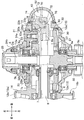
図4に示すように、ボディ10内には、左右方向に延在するハンドル軸5が設けられている。ハンドル軸5は、軸受5a,5bを介してボディ10と蓋部材30とに回転可能に支持されている。ハンドル軸5には機能部材としてドライブギャ6および軸筒(歯車)6aが固定されている。ハンドル軸5の左端部には、連結軸5cを介してハンドル5d(図1参照)が取り付けられている。
ドライブギャ6は、ハンドル軸5の左側に固定されているとともに、前側でピニオンギャ7aに噛合している。軸筒6aは、ハンドル軸5の右側に固定されているとともに、後側で連動歯車74に噛合している。
このため、ハンドル5dの巻き取り操作が行われると、巻き取り操作による駆動力がハンドル軸5、ドライブギャ6、ピニオンギャ7aを介して駆動軸筒7に伝達し、駆動軸筒7とともにロータ2が回転する。また、これとともにスプール3がスプール軸8やスプール往復動装置70を介して前後往復動される。これにより、釣糸は、ロータ2(図1参照)の図示しない釣糸案内部を介してスプール3の巻回胴部3a(図1参照)に均等に巻回される。
As shown in FIG. 4, a
The
For this reason, when the winding operation of the
次に、各部の構成について詳細に説明する。図3に示すように、側部開口部13は、円筒状の内周面13aを備えており、ボディ10と同芯円状に形成されている。内周面13aは、ハンドル軸5の外周面と平行な面である。内周面13aの奥側には、図5(c)に示すように、雌ねじ13bが形成されている。側部開口部13の開口周縁部には、断面凹状の嵌合受部17が周方向に亘って形成されている。嵌合受部17は、底面部17aと、この底面部17aから断面アール状に立ち上がる立上り部17bと、を備えている。
Next, the configuration of each unit will be described in detail. As shown in FIG. 3, the
側部開口部13の内径は、図3,図4に示すように、ドライブギャ6の外径よりも大きく形成されている。これにより、ハンドル軸5、ドライブギャ6および軸筒6aは、側部開口部13を通じて収容空間S1内に挿入され、ボディ10に組み付けられる。別言すれば、側部開口部13は、円形で大径のドライブギャ6を挿通可能な相似形の大きな内径に形成されている。
The inner diameter of the
収容空間S1内には、図3に示すように、支持リブ19が形成されている。支持リブ19は収容空間S1の底部となるボディ10の右側部の内面10gに突設されている。支持リブ19には上部支持部19a,下部支持部19bが一体に設けられている。上部支持部19aは後方へ向けて開口する有底円筒状を呈している。上部支持部19aには、スプール往復動装置70のガイド軸71の前端部が支持されている。下部支持部19bは前後方向へ貫通する円筒状を呈しており、軸受部として機能している。下部支持部19bには、駆動軸筒7の後端部が支持されている。
As shown in FIG. 3,
蓋部材30は、図2に示すように、側部開口部13に取り付けられ、側部開口部13を液密に閉塞するとともに、ハンドル軸5の左端側を支持する役割をなす。蓋部材30は、図5(b)に示すように、断面が山形状を呈しており、周壁部31と、周壁部31の中央部に一体的に設けられた円筒部32と、周壁部31の外周縁部に設けられた円筒状の挿入部33と、を備えている。
The
周壁部31の外側面(左側面)および内周面(右側面)には、肉抜き部31bが形成されている。これにより蓋部材30の軽量化が図られている。円筒部32は、奥側となる右側部が段状に拡径しており、この拡径した部分に軸受5a(図4参照)が収容されている。蓋部材30は、軸受5aを介してハンドル軸5の左端側を支持している。
なお、図4に示すように、ハンドル軸5の右端側は、軸受5bを介してボディ10に設けられたハンドル支持部10eに支持されている。
The outer surface of the peripheral wall 31 (left side) and the inner peripheral surface (the right side), the
As shown in FIG. 4, the right end side of the
挿入部33は、側部開口部13に向けて延在し、側部開口部13に挿入される部位である。挿入部の先端(右端)の外周部には、図5(c)に示すように、雄ねじ33aが形成されている。雄ねじ33aは、側部開口部13の雌ねじ13bに螺合可能である。これにより、側部開口部13に対して蓋部材30自体を螺合によって締結固定することができるので、蓋部材30の組み付けが行い易い。
The
雄ねじ33aよりも基端側となる挿入部33の外周部には、側部開口部13の内周面13aに当接する円筒状の当接面(当接部)33bが形成されている。当接面33bは、側部開口部13に蓋部材30を螺合により取り付けた際に、側部開口部13の内周面13aに対して周方向に当接して調芯作用をなす。これにより、側部開口部13と蓋部材30との同芯度が得られる。したがって、加工精度を高めなくても側部開口部13と蓋部材30との間に隙間が形成され難い。また、蓋部材30の中心とボディ10の中心とが一致するので、ハンドル軸5の傾倒が防止され、ハンドル5dの回転操作性および噛合性能が安定向上する。
なお、当接面33bは、側部開口部13の内周面13aに対して周方向に間隔を空けて部分的に当接するように構成してもよい。
A cylindrical contact surface (contact portion) 33b that contacts the inner
The
挿入部33の外周面には、雄ねじ部33aと当接面33bとの間に収容凹部33cが形成されている。収容凹部33cには、シール材としてOリング33dが外嵌されている。
On the outer peripheral surface of the
蓋部材30の外周縁部には、周方向外側に延在するフランジ状の嵌合部37が形成されている。嵌合部37は、側部開口部13の嵌合受部17の立上り部17bとの間に僅かな隙間(図示では隙間を有しているが接触嵌合も可能)を有した状態で底面部17aに当接し、嵌合受部17に対してインロー嵌合する。このようなインロー嵌合によって、嵌合部37は、側方への突出量が抑えられている。これにより、リール操作時等に釣糸が解れた場合にも、解れた釣糸が蓋部材30の外周縁部に引っ掛かり難くなっている。
また、インロー嵌合によって防塵防水を図ることができる。これにより、例えば、海水や水、あるいはこれらに混じった砂、異物等が侵入するのを遮ることができる。つまり、インロー嵌合部によって釣糸や海水、異物等の侵入防止が実現される。
A flange-like
Moreover, dustproof and waterproofing can be achieved by fitting with a spigot. Thereby, for example, seawater, water, sand mixed in them, foreign matter, or the like can be blocked. That is, the inlay fitting portion can prevent intrusion of fishing line, seawater, foreign matter and the like.
なお、図5(c)に示すように、蓋部材30の外周縁部の外面30gと、側部開口部13の外周縁部の外面13gとは、嵌合部37(嵌合受部17)を挟んで略連続する傾斜面とされている。これによって、解れた釣糸がより引っ掛かり難い構成となっている。
In addition, as shown in FIG.5 (c), the
図5(c)に示すように、嵌合部37と当接面33bとの間には、断面湾曲凹状の小径部38が形成されている。小径部38には、グリスやオイル等の潤滑剤が塗布されている。潤滑剤によって、蓋部材30のスムーズな取り付けが可能になるとともに、側部開口部13の内周面13aとのシール性が高められている。
なお、同様に、嵌合受部17や嵌合部37に対してグリスやオイル等の潤滑剤を塗布してもよい。
As shown in FIG. 5C, a small-
Similarly, a lubricant such as grease or oil may be applied to the fitting receiving
ボディ10とボディ前部12との境界部には、図2,3に示すように、薄板状を呈するフランジ部16が設けられている。フランジ部16の左側部には、図2に示すように、凹状部16bが形成されている。凹状部16bは、蓋部材30の前端部30eの形状に沿って前方へ向けて凹設されている。凹状部16bにより、蓋部材30の前端部30eは、フランジ部16の上部後面16aよりも前方に入り込むように位置している。また、蓋部材30の前端部30eは、図1に示すように、ロータ2との位置関係において、ロータ2の最後端部2aよりも前方に位置している。さらに、蓋部材30の前端部30eは、図2に示すように、ボディ前部12を覆う有底円筒状のカバー12aとの位置関係において、カバー12aの後端部12bよりも前方に位置している。このような位置関係に蓋部材30の前端部30eが位置することによって、ボディ10の前後方向のコンパクト化を図りつつ、蓋部材30の大径化が可能となっている。なお、凹状部16bは、蓋部材30を取り付ける際の逃げ部となる。
As shown in FIGS. 2 and 3, a
ボディ10の左側部の後部には、図2,3に示すように、側部開口部13(蓋部材30)に沿うようにしてボディ10の上部から下部に亘る湾曲状の架橋部14が形成されている。架橋部14の外形状は、側部開口部13(蓋部材30)と同芯円状に形成されている。架橋部14は、図3に示すように、側部開口部13の開口縁部の一部を構成している。
なお、架橋部14は、側部開口部13と同芯円状に形成されたものを示したが、これに限られることはなく、側部開口部13の中心(ハンドル軸5の中心)に対して前側または後側に偏芯したものであってもよい。また、架橋部14は、側面視で外形状が直線状部分を含むものであってもよい。
As shown in FIGS. 2 and 3, a
In addition, although the bridge | bridging
ボディ10の後部には、図6(a)に示すように、後部開口部15が形成されている。後部開口部15は収容空間S1に連通している。後部開口部15の周縁部には、後方へ向けて突出する縁リブ15aが形成されている。本実施形態では、図3に示すように、後部開口部15を通じてスプール往復動装置70の連動歯車74の一部、ストローク位置が最後端位置にあるときの摺動子72の一部、およびガイド軸71の後端部71aが、ボディ10の後部から後方へ突出している。つまり、後部開口部15は、これらの部材が挿通配置される大きさおよび形状を備えている。なお、これらの部材が後部開口部15を通じてボディ10の後方に突出するので、その分、収容空間S1は、コンパクトな大きさに形成されている。
As shown in FIG. 6A, a
後部開口部15の周りには、図6(a)に示すように、カバー装着部18が形成されている。カバー装着部18には、シール部材50を介して保護カバー40が取り付けられている(図6(b)参照)。保護カバー40の内側には、図4に示すように、空間部S2が形成されている。空間部S2には、前記したように、ボディ10の後部から突出した連動歯車74の一部および摺動子72の一部が収容される。つまり、連動歯車74の一部および摺動子72の一部は、シール部材50を介して装着される保護カバー40で覆われて液密に収容されている(図3参照)。ボディ10の後部から突出するガイド軸71の後端部71aは、図3,図7(a)に示すように、保護カバー40の内側に設けられる支持部43cに支持されている。
スプール軸8およびスプール往復動装置70の各部材は、後記するように、後部開口部15を通じてリール本体1の後方から組み付けられる。
A
Each member of the
ボディ10の右側部には、図4に示すように、取付部20が凹設されている。取付部20は、図7(a)に示すように、側面視でカム形状を呈しており、ボディ10の左側部に設けられた円筒状のハンドル支持部10e(図4参照)の周りに形成されている。取付部20には、同じくカム形状に形成された支持部材21が取り付けられている。
As shown in FIG. 4, a mounting
支持部材21は、図7(b)(c)に示すように、板状を呈している。支持部材21は、外周部22aが厚肉に形成され、内周部22bが薄肉に形成されている。外周部22aの先端左側面には、左側方へ突出するボス部23が形成されている。ボス部23は、図4に示すように、取付部20に形成された挿入孔20aを通じて収容空間S1に突出している。ボス部23には、軸受23bを介して連動歯車74が支持されており、ボス部23は、連動歯車74の支軸として機能している。つまり、連動歯車74は、ボディ10に対して直接支持されることなく、ボディ10に取り付けられる支持部材21によって支持されるように構成されている。したがって、ボディ10は、その右側部の内面に、連動歯車74を支持するためのボス部を形成する必要のない構造となっている。
As shown in FIGS. 7B and 7C, the
これによって、収容空間S1の底面を構成しているボディ10の右側部の内面を略平らに形成することができ、スプール軸8やスプール往復動装置70の各部材を後部開口部15を通じてスムーズに組み付けることができる。
As a result, the inner surface of the right side portion of the
軸受23bは、図4に示すように、内輪の右端がボス部23の段部に当て付けられており、外輪の右端が連動歯車74の段部に当て付けられている。また、軸受23bは、内輪の左端がねじ穴23aに螺合される止めねじ23cで抜け止めされている。
As shown in FIG. 4, in the
取付部20における挿入孔20aの周縁部には、防塵防水用としてOリング23d(図7(a)に破線で図示)が配置されている。
An O-
支持部材21のボス部23の近傍には、図7(b)(c)に示すように、突部26が設けられている。突部26は、取付部20に向けて突出しており、取付部20に設けられた位置決め穴20c(図7(a)参照)に係止される。突部26は、取付部20に対する支持部材21の位置決め用部材として機能する。
As shown in FIGS. 7B and 7C, a
支持部材21の内周部22bは、図7(b)に示すように、円形帯状に形成されている。内周部22bは、図4に示すように、ボディ10のハンドル支持部10eを囲んでいる。内周部22bの右側面には、図4に示すように、固定部材24の環状部24aが当接している。
固定部材24は、支持部材21を抜け止め固定する部材であり、ボディ10のハンドル支持部10eに螺合により取り付けられている。固定部材24を締め付けることで、環状部24aが支持部材21の内周部22bに当接し、支持部材21が取付部20に固定される。固定部材24の先端部24bには、螺合によりハンドルキャップ25が取り付けられている。
As shown in FIG. 7B, the inner
The fixing
支持部材21を取付部20に取り付けることによって、連動歯車74を支持する位置(ボス部23の位置)が決まり、ハンドル軸5と連動歯車74の軸との軸間距離が決定する。これにより、前記軸間距離が異なる距離となるように支持部材21の仕様を変更することによって、異なる径(異なる仕様)の連動歯車74を支持することができ、ストローク量を変更することが可能となる。したがって、魚釣用スピニングリール100の仕様変更を低コストで容易に行うことができる。この場合、異なる仕様の支持部材21を取付可能とするために、取付部20の挿入孔20aの形状を、例えば、大径の円形状に形成したり、長穴形状に形成したりしてもよい。
By attaching the
なお、支持部材21によって仕様変更が可能となるので、リール本体1の共有化も可能となる。したがって、リール本体1を製造する際の金型をリールの仕様毎に数種類用意する必要がなくなり、仕様変更に伴うコストの低減を図ることができる。また、リールの大きさの枠を超えた部品の共通化も可能となる。これにより、リール価格上昇の抑制を図ることも可能である。
Since the specification can be changed by the
また、ボディ10にボスを形成する必要がないので、架橋部14とボス部23とが側面視で重なるレイアウトのような加工に困難性を有する構造であっても、容易に実現することができる。
In addition, since it is not necessary to form a boss on the
スプール往復動装置70の摺動子72は、ストロークの最後端位置にある場合に、図8(a)に示すように、ボディ10の後部(架橋部14で仕切られる部位)から後方へ突出する。また、摺動子72のハンドル軸5の対向部には凹部72aが形成されており、ストロークの最前端位置にある場合に、図8(b)に示すように、ハンドル軸5の中心O1を上下方向に凹部72aで受け入れて跨ぐように位置する。このとき、スプール軸8の後端部8bは、ハンドル軸5の中心O1よりも前方に位置しており、その分、スプール軸8のストローク量が長くなっている。
When the
保護カバー40は、図2,図4に示すように、ボディ10の後部に設けられたカバー装着部18にシール部材50を介して着脱可能に取り付けられる。
保護カバー40は、図2に示すように、側面視で略三日月形に形成されている。保護カバー40は、図6(b)に示すように、後面視でスプール軸8(図3参照)を通る中心線O2を基準として、中心線O2の左側よりも右側が幅広な形状に形成されている。保護カバー40は、図4に示すように、横断面が凹状に形成されており、ボディ10の収容空間S1に連通する空間部S2を形成している。空間部S2は、保護カバー40の内側の上下方向の略全体に亘って形成されている。保護カバー40は、図8(a)に示すように、その上端部および下端部に設けられたねじ孔40a,40bに挿通した固定ねじ40cを、カバー装着部18の上部ボス部10cおよび下部ボス部10dに締め付けることによってカバー装着部18に取り付けられる。
As shown in FIGS. 2 and 4, the
As shown in FIG. 2, the
次に、ボディ10に対するスプール軸8およびスプール往復動装置70の組み付け手順について説明する。組み付けにあたって、はじめに、後部開口部15を通じてスプール往復動装置70のガイド軸71を収容空間S1に挿入し、ガイド軸71の先端部を上部支持部19aに差し込む。この状態でガイド軸71の後端部71aは、後部開口部15を通じて、ボディ10の後部から後方に突出する。
Next, a procedure for assembling the
続いて、スプール軸8の後端の連結部8a(図4参照)に、図示しないねじを用いて摺動子72を連結する。そして、摺動子72に連動歯車74を近づけ、連動歯車74の偏芯突部75を摺動子72の案内溝73に係合させた状態にして、スプール軸8とともに摺動子72および連動歯車74を後部開口部15を通じて収容空間S1に挿入する。なお、連動歯車74には予め軸受23bを装着しておく。
Subsequently, the
その後、スプール軸8の先端部を駆動軸筒7の空洞部に挿入する。挿入する過程で、摺動子72が後部開口部15に近づいたら、ボディ10の後部から突出しているガイド軸71の後端部71aに摺動子72の図示しないガイド孔を合わせ、ガイド軸71に摺動子72を係合する。これにより摺動子72および連動歯車74はガイド軸71に沿って挿入される。
Thereafter, the tip of the
その後、ボディ10の右側方からボディ10の取付部20に支持部材21を取り付け、挿入孔20aを通じてボス部23を収容空間S1内に突出させ、連動歯車74の軸受23bに挿通する。
Thereafter, the
その後、軸受23bのねじ穴23aに止めねじ23cを螺合し、ボス部23に連動歯車74を抜け止め保持する。
以上により、後部開口部15を通じてスプール軸8およびスプール往復動装置70を収容空間S1に組み付けることができる。なお、上記組み付け順は一例を示すものであり、適宜状況に応じて変更可能である。
Thereafter, a
As described above, the
このように、後部開口部15を通じてスプール往復動装置70を容易に組み付けることができるので、生産性が向上する。このことは、コストの低減に寄与する。また、容易に組み付けることができるので、リール本体1における構成部材の配置の自由度が高まり、設計の自由度が増す。
In this way, the
さらに、支持部材21の仕様を変更することによって、ハンドル軸5と連動歯車74の軸との軸間距離を異なる距離に変更して外径の異なる連動歯車74を支持することができるので、スプール軸8のストローク長を容易に変更することができる。
Further, by changing the specification of the
以上説明した本実施形態の魚釣用スピニングリール100によれば、側部開口部13に対して蓋部材30自体を螺合によって締結固定することができるので、蓋部材30の組み付けが行い易い。蓋部材30の外周縁部に設けられた嵌合部37は、側部開口部13の開口周縁部に設けられた嵌合受部17に対してインロー嵌合するので、双方の当接面が外部に露出することがない。したがって、仮に双方の当接面に隙間が形成されたとしても、インロー嵌合によって隙間が露出することが防止され、例えば、海水や水、あるいはこれらに混じった砂、異物等が侵入するのを遮ることができる。つまり、インロー嵌合によって海水や異物等の侵入防止や釣糸の糸絡み、糸噛みの防止が実現される。
According to the
また、螺合により、側部開口部13に対して蓋部材30が周方向に均一な締結力をもって固定されるので、蓋部材30の取付強度を確保することができる。したがって、リール本体や蓋部材1の耐久性の向上、さらにはハンドル軸5の支持強度の向上が期待できる。
また、側部開口部13と蓋部材30とが大径であるので、リード角を小さく設定することができる。したがって、蓋部材30が緩み難いという利点も得られる。
Further, since the
Further, since the
また、締結固定した状態で、蓋部材30の外周縁部に設けられた嵌合部37は、側部開口部13の開口周縁部に設けられた嵌合受部17に対してインロー嵌合するので、インロー嵌合部が防塵防水部として機能する。これにより、例えば、海水や水、あるいはこれらに混じった砂、異物等が侵入するのを遮ることができる。つまり、インロー嵌合部によって海水や異物等の侵入防止や釣糸の糸絡み、糸噛みの防止が実現される。
Moreover, the
また、蓋部材30の外周縁部の外面30gと、側部開口部13の外周縁部の外面13gとは、嵌合部37(嵌合受部17)を挟んで略連続する傾斜面とされている。これによって、解れた釣糸がより引っ掛かり難くなっている。
The
また、蓋部材30に側部開口部13との同芯度を得るための当接面33bが形成されており、蓋部材30の中心とボディ10の中心とが一致するので、ハンドル軸5の傾倒が防止され、ハンドル5dの回転操作性および噛合性能が安定向上する。
Further, a
また、ボディ10と側部開口部13とが同芯円状に形成されているので、釣糸巻き取り時等にボディ10に生じる応力をボディ10の周方向に好適に分散することができる。したがって、ボディ10の耐久性の向上ひいてはリール本体1の耐久性の向上を図ることができる。
In addition, since the
また、円弧状の架橋部14により、ボディ10の後部の強度を確保することができるので、スプール往復動装置70の作動性の向上、ひいては巻き取り操作性の向上を図ることができる。
Further, since the strength of the rear portion of the
また、スプール往復動装置70の連動歯車74の一部、ストローク位置が最後端位置にあるときの摺動子72の一部、およびガイド軸71の後端部71aをリール本体1(ボディ10)の後部の後方に配置することができるので、リール本体1(ボディ10)の小型化を図ることができる。また、リール本体1(ボディ10)の後部の後方のスペースを有効利用してスプール往復動装置70の前後ストロークを好適に確保することができる。
Further, a part of the interlocking
以上、本発明の実施形態について説明したが、本発明は、上記した実施形態に限定されることはなく、種々変形することが可能である。
例えば、蓋部材30の嵌合部37は、側部開口部13の内側にて嵌合受部17にインロー嵌合するように構成してもよい。このように構成することで、防塵防水性がより向上する。また、ボディ10からの蓋部材30の嵌合部37の突出がより抑えられるので、解れた釣糸の引っ掛かりもより好適に回避することができる。
As mentioned above, although embodiment of this invention was described, this invention is not limited to above-described embodiment, It can change variously.
For example, the
また、前記実施形態では、スプール軸8の後部8aに連結固定した摺動子72を、ハンドル軸5に連動回転する連動歯車74(構成部材)の偏芯突部75に係合させ、ハンドル軸5の回転をスプール軸8の前後往復動に変換させるスプール往復動装置で説明したが、これに限られることはなく、例えば、ピニオンギャ7aを有する駆動軸筒7に連動回転する公知の螺軸(構成部材)に摺動子72を係合させてなるスプール往復動装置に実施してもよい。
In the above-described embodiment, the
1 リール本体
3 スプール
5 ハンドル軸
6 ドライブギャ
6a 軸筒(歯車)
8 スプール軸
10 ボディ
11 脚部
13 側部開口部
13b 雌ねじ(雌ねじ部)
14 架橋部
15 後部開口部
17 嵌合部
30 蓋部材
33a 雄ねじ(雄ねじ部)
33b 当接面(当接部)
37 嵌合受部
70 スプール往復動装置
S1 収容空間
1 Reel body 3
8
14
33b Contact surface (contact portion)
37
Claims (5)
前記側部開口部および前記蓋部材は円形であり、
前記側部開口部の内周部に設けられた雌ねじ部と、
前記蓋部材の外周部に設けられ、前記雌ねじ部に螺合する雄ねじ部と、
前記側部開口部の開口周縁部に設けられた嵌合受部と、
前記蓋部材の外周縁部に設けられ、前記嵌合受部に対してインロー嵌合する嵌合部と、を備えたことを特徴とする魚釣用スピニングリール。 A fishing spinning reel comprising: a reel body; and a lid member that closes a side opening provided in a side portion of the reel body, and the handle shaft is rotatably supported by the reel body and the lid member Because
The side opening and the lid member are circular,
An internal thread provided on the inner periphery of the side opening;
A male screw portion provided on an outer peripheral portion of the lid member and screwed into the female screw portion;
A fitting receiving portion provided at an opening peripheral edge of the side opening;
A fishing spinning reel comprising: a fitting portion that is provided on an outer peripheral edge portion of the lid member and that is fitted in-lay with the fitting receiving portion.
前記ボディは、前記ハンドル軸の軸方向から見て外形状が略円形に形成されており、
前記側部開口部は、前記ボディと同芯円状に形成されていることを特徴とする請求項1または請求項2に記載の魚釣用スピニングリール。 The reel main body includes a body in which a functional member is accommodated, and a leg portion provided continuously with an upper portion of the body.
The body has a substantially circular outer shape when viewed from the axial direction of the handle shaft,
3. The fishing spinning reel according to claim 1, wherein the side opening is formed concentrically with the body.
前記ボディの後部には、後方へ向けて開口する後部開口部が形成されており、
前記スプール往復動装置を構成する構成部材の少なくとも一部は、前記後部開口部を通じて前記ボディの後部から突出することを特徴とする請求項3または請求項4に記載の魚釣用スピニングリール。 A drive gear that is rotationally driven by the handle shaft, a spool shaft on which a spool around which a fishing line is wound is mounted, a rear end side of the spool shaft is supported, and the drive gear is driven as the drive gear is driven. A spool reciprocating device that reciprocates the spool shaft in the front-rear direction, and
A rear opening that opens rearward is formed at the rear of the body,
5. The fishing spinning reel according to claim 3, wherein at least a part of a component constituting the spool reciprocating device protrudes from a rear portion of the body through the rear opening.
Priority Applications (7)
| Application Number | Priority Date | Filing Date | Title |
|---|---|---|---|
| JP2015247476A JP6491594B2 (en) | 2015-12-18 | 2015-12-18 | Fishing spinning reel |
| CN201680073937.9A CN108471734B (en) | 2015-12-18 | 2016-12-16 | Spinning reel for fishing |
| CN202011518215.4A CN112674049A (en) | 2015-12-18 | 2016-12-16 | Spinning reel for fishing |
| EP16875811.8A EP3391743B1 (en) | 2015-12-18 | 2016-12-16 | Spinning reel for fishing |
| US16/063,058 US10856535B2 (en) | 2015-12-18 | 2016-12-16 | Spinning reel for fishing |
| PCT/JP2016/087656 WO2017104837A1 (en) | 2015-12-18 | 2016-12-16 | Spinning reel for fishing |
| KR1020187016641A KR20180093929A (en) | 2015-12-18 | 2016-12-16 | Spinning reel for fishing |
Applications Claiming Priority (1)
| Application Number | Priority Date | Filing Date | Title |
|---|---|---|---|
| JP2015247476A JP6491594B2 (en) | 2015-12-18 | 2015-12-18 | Fishing spinning reel |
Publications (3)
| Publication Number | Publication Date |
|---|---|
| JP2017108718A JP2017108718A (en) | 2017-06-22 |
| JP2017108718A5 JP2017108718A5 (en) | 2018-03-29 |
| JP6491594B2 true JP6491594B2 (en) | 2019-03-27 |
Family
ID=59080632
Family Applications (1)
| Application Number | Title | Priority Date | Filing Date |
|---|---|---|---|
| JP2015247476A Active JP6491594B2 (en) | 2015-12-18 | 2015-12-18 | Fishing spinning reel |
Country Status (1)
| Country | Link |
|---|---|
| JP (1) | JP6491594B2 (en) |
Family Cites Families (3)
| Publication number | Priority date | Publication date | Assignee | Title |
|---|---|---|---|---|
| JP2572087Y2 (en) * | 1991-10-15 | 1998-05-20 | 株式会社シマノ | Spinning reel |
| JPH0762U (en) * | 1993-06-08 | 1995-01-06 | 株式会社シマノ | Spinning reel |
| JP4012033B2 (en) * | 2002-10-10 | 2007-11-21 | ダイワ精工株式会社 | Fishing spinning reel |
-
2015
- 2015-12-18 JP JP2015247476A patent/JP6491594B2/en active Active
Also Published As
| Publication number | Publication date |
|---|---|
| JP2017108718A (en) | 2017-06-22 |
Similar Documents
| Publication | Publication Date | Title |
|---|---|---|
| JP6590684B2 (en) | Fishing reel | |
| JP6590683B2 (en) | Fishing spinning reel | |
| US10856535B2 (en) | Spinning reel for fishing | |
| JP6587925B2 (en) | Fishing spinning reel | |
| KR20150109274A (en) | Spinning reel for fishing | |
| WO2017212672A1 (en) | Spinning reel for fishing | |
| JP6491594B2 (en) | Fishing spinning reel | |
| JP6590769B2 (en) | Fishing spinning reel | |
| JP2018033403A (en) | Rotor drive waterproof structure and spinning reel | |
| JP2018014975A (en) | Fishing spinning reel | |
| JP2017216946A (en) | Fishing spinning reel | |
| JP2019176785A (en) | Fishing spinning reel | |
| JP6622667B2 (en) | Fishing spinning reel | |
| JP6606475B2 (en) | Fishing spinning reel | |
| CN110313452B (en) | Spinning reel for fishing | |
| JP2018082675A (en) | Fishing spinning reel | |
| JP2012029650A (en) | Spinning reel for fishing | |
| JP5954875B2 (en) | Fishing spinning reel | |
| JP6738471B2 (en) | Spinning reel for fishing | |
| JP6586005B2 (en) | Fishing spinning reel | |
| JP5954874B2 (en) | Fishing reel | |
| KR102005125B1 (en) | Spinning fishing reel | |
| JP6606474B2 (en) | Fishing spinning reel | |
| JP2017108716A (en) | Fishing spinning reel | |
| JP2019176783A (en) | Spinning reel for fishing |
Legal Events
| Date | Code | Title | Description |
|---|---|---|---|
| A521 | Request for written amendment filed |
Free format text: JAPANESE INTERMEDIATE CODE: A523 Effective date: 20180215 |
|
| A621 | Written request for application examination |
Free format text: JAPANESE INTERMEDIATE CODE: A621 Effective date: 20180215 |
|
| TRDD | Decision of grant or rejection written | ||
| A01 | Written decision to grant a patent or to grant a registration (utility model) |
Free format text: JAPANESE INTERMEDIATE CODE: A01 Effective date: 20190219 |
|
| A61 | First payment of annual fees (during grant procedure) |
Free format text: JAPANESE INTERMEDIATE CODE: A61 Effective date: 20190301 |
|
| R150 | Certificate of patent or registration of utility model |
Ref document number: 6491594 Country of ref document: JP Free format text: JAPANESE INTERMEDIATE CODE: R150 |
|
| R250 | Receipt of annual fees |
Free format text: JAPANESE INTERMEDIATE CODE: R250 |
|
| R250 | Receipt of annual fees |
Free format text: JAPANESE INTERMEDIATE CODE: R250 |
|
| R250 | Receipt of annual fees |
Free format text: JAPANESE INTERMEDIATE CODE: R250 |