JP6589741B2 - Image processing device - Google Patents
Image processing device Download PDFInfo
- Publication number
- JP6589741B2 JP6589741B2 JP2016104488A JP2016104488A JP6589741B2 JP 6589741 B2 JP6589741 B2 JP 6589741B2 JP 2016104488 A JP2016104488 A JP 2016104488A JP 2016104488 A JP2016104488 A JP 2016104488A JP 6589741 B2 JP6589741 B2 JP 6589741B2
- Authority
- JP
- Japan
- Prior art keywords
- area
- width
- unit
- luminance
- region
- Prior art date
- Legal status (The legal status is an assumption and is not a legal conclusion. Google has not performed a legal analysis and makes no representation as to the accuracy of the status listed.)
- Active
Links
- 230000009467 reduction Effects 0.000 claims description 11
- 230000002093 peripheral effect Effects 0.000 claims description 10
- 238000012217 deletion Methods 0.000 claims description 4
- 230000037430 deletion Effects 0.000 claims description 4
- 238000000034 method Methods 0.000 description 33
- 230000008569 process Effects 0.000 description 14
- 239000000470 constituent Substances 0.000 description 9
- 230000006870 function Effects 0.000 description 7
- 230000014509 gene expression Effects 0.000 description 5
- 230000001133 acceleration Effects 0.000 description 3
- 238000010586 diagram Methods 0.000 description 2
- 239000004065 semiconductor Substances 0.000 description 2
- 230000008901 benefit Effects 0.000 description 1
- 230000006835 compression Effects 0.000 description 1
- 238000007906 compression Methods 0.000 description 1
- 230000000694 effects Effects 0.000 description 1
- 238000003672 processing method Methods 0.000 description 1
- 230000020509 sex determination Effects 0.000 description 1
- 230000009466 transformation Effects 0.000 description 1
- 230000000007 visual effect Effects 0.000 description 1
Images


Classifications
-
- H—ELECTRICITY
- H04—ELECTRIC COMMUNICATION TECHNIQUE
- H04N—PICTORIAL COMMUNICATION, e.g. TELEVISION
- H04N23/00—Cameras or camera modules comprising electronic image sensors; Control thereof
- H04N23/70—Circuitry for compensating brightness variation in the scene
-
- H—ELECTRICITY
- H04—ELECTRIC COMMUNICATION TECHNIQUE
- H04N—PICTORIAL COMMUNICATION, e.g. TELEVISION
- H04N23/00—Cameras or camera modules comprising electronic image sensors; Control thereof
- H04N23/60—Control of cameras or camera modules
- H04N23/67—Focus control based on electronic image sensor signals
- H04N23/673—Focus control based on electronic image sensor signals based on contrast or high frequency components of image signals, e.g. hill climbing method
-
- G—PHYSICS
- G06—COMPUTING; CALCULATING OR COUNTING
- G06T—IMAGE DATA PROCESSING OR GENERATION, IN GENERAL
- G06T1/00—General purpose image data processing
-
- G—PHYSICS
- G06—COMPUTING; CALCULATING OR COUNTING
- G06T—IMAGE DATA PROCESSING OR GENERATION, IN GENERAL
- G06T5/00—Image enhancement or restoration
- G06T5/40—Image enhancement or restoration by the use of histogram techniques
-
- H—ELECTRICITY
- H04—ELECTRIC COMMUNICATION TECHNIQUE
- H04N—PICTORIAL COMMUNICATION, e.g. TELEVISION
- H04N7/00—Television systems
- H04N7/18—Closed-circuit television [CCTV] systems, i.e. systems in which the video signal is not broadcast
Description
本発明は画像処理装置に関する。 The present invention relates to an image processing apparatus.
従来、車載カメラを用いて車両の周辺を撮像し、得られた画像を車室内のディスプレイに表示する技術が知られている。車載カメラは、例えば、ドライバにとって車両の死角となる範囲を撮像する。また、車載カメラとディスプレイとを備えるシステムを、ルームミラーやサイドミラーの代わりに用いることが提案されている。上記の技術は特許文献1に開示されている。 2. Description of the Related Art Conventionally, there has been known a technique for capturing the periphery of a vehicle using an in-vehicle camera and displaying the obtained image on a display in a vehicle interior. For example, the in-vehicle camera images a range that is a blind spot of the vehicle for the driver. In addition, it has been proposed to use a system including an in-vehicle camera and a display instead of a room mirror or a side mirror. The above technique is disclosed in Patent Document 1.
降雪時等、特定の環境下では、車載カメラで撮像した画像のコントラストが低く、視認性が低い。この場合ドライバは、表示された画像において、例えば、雪で覆われた路面の凹凸、路面と雪壁との境界等を認識することが困難となる。 Under certain circumstances, such as when it is snowing, the contrast of the image captured by the in-vehicle camera is low and the visibility is low. In this case, it is difficult for the driver to recognize, for example, the unevenness of the road surface covered with snow, the boundary between the road surface and the snow wall, etc. in the displayed image.
本発明は、こうした問題に鑑みてなされたものであり、視認性が高い画像を生成できる画像処理装置を提供することを目的としている。 SUMMARY An advantage of some aspects of the invention is that it provides an image processing apparatus capable of generating an image with high visibility.
本発明の画像処理装置(1)は、車両の周辺を表す画像を取得する画像取得ユニット(7)と、画像の一部である判断領域(39)において、視認性が予め設定された閾値以下であるか否かを判断する視認性判断ユニット(12)と、視認性が閾値以下である視認性判断ユニットが判断した場合、画像における輝度を調整する輝度調整ユニット(13)とを備える。 In the image processing apparatus (1) of the present invention, in an image acquisition unit (7) that acquires an image representing the periphery of a vehicle and a determination area (39) that is a part of the image, the visibility is equal to or less than a preset threshold value. A visibility determination unit (12) that determines whether or not the brightness is determined, and a brightness adjustment unit (13) that adjusts the brightness in the image when the visibility determination unit whose visibility is equal to or less than a threshold is determined.
前記の輝度調整ユニットは、判断領域における輝度ヒストグラムにて度数が最大である輝度aを取得する輝度取得ユニット(15)と、画像における輝度範囲を、輝度aが属する領域Aを含む複数の領域に区分する区分ユニット(17)と、複数の領域のうち、属する画素数が予め設定された閾値以下である領域Xの少なくとも一部を削除する領域X削除ユニット(19)と、領域Aを、少なくとも、領域Xにおいて削除した幅ΔXだけ、領域Xの側に拡張する領域A拡張ユニット(19)と、領域Xと領域Aとの間に他の領域が存在する場合は、他の領域を領域Xの側に移動させる領域移動ユニット(19)とを備える。 The luminance adjustment unit includes a luminance acquisition unit (15) that acquires the luminance a having the highest frequency in the luminance histogram in the determination region, and the luminance range in the image into a plurality of regions including the region A to which the luminance a belongs. A sorting unit (17) for sorting, a region X deleting unit (19) for deleting at least a part of a region X in which the number of pixels belonging to the plurality of regions is equal to or less than a preset threshold, and at least a region A If there is another area between the area A and the area A and the area A expansion unit (19) extending to the area X side by the width ΔX deleted in the area X, the other area is designated as the area X. And an area moving unit (19) for moving to the side.
本発明の画像処理装置は領域Aを拡張する。そのため、領域Aにおけるコントラストを向上させ、視認性を向上させることができる。また、拡張幅ΔAのうち、少なくとも一部は、画素数が少ない領域Xを削除して得られるものである。そのため、領域A及び領域X以外の領域における縮小幅を抑制することができる。その結果、輝度を調整した後でも、画像の画質が劣化しにくい。 The image processing apparatus of the present invention extends the area A. Therefore, the contrast in the region A can be improved and the visibility can be improved. Further, at least a part of the expansion width ΔA is obtained by deleting the region X having a small number of pixels. For this reason, the reduction width in the region other than the region A and the region X can be suppressed. As a result, the image quality is unlikely to deteriorate even after the luminance is adjusted.
画像処理装置は、領域Xと領域Aとの間に他の領域が存在する場合は、他の領域を領域Xの側に移動させる。そのため、領域Xが領域Aと隣接していない場合でも、領域Aを領域Xの側に拡張することができる。 When another area exists between the area X and the area A, the image processing apparatus moves the other area to the area X side. Therefore, even when the region X is not adjacent to the region A, the region A can be expanded to the region X side.
なお、この欄及び特許請求の範囲に記載した括弧内の符号は、一つの態様として後述する実施形態に記載の具体的手段との対応関係を示すものであって、本発明の技術的範囲を限定するものではない。 In addition, the code | symbol in the parenthesis described in this column and a claim shows the correspondence with the specific means as described in embodiment mentioned later as one aspect, Comprising: The technical scope of this invention is shown. It is not limited.
本開示の実施形態を図面に基づき説明する。
<第1実施形態>
1.画像処理装置1の構成
画像処理装置1の構成を、図1、図2に基づき説明する。画像処理装置1は車両に搭載される車載装置である。画像処理装置1を搭載する車両を以下では自車両とする。
An embodiment of the present disclosure will be described with reference to the drawings.
<First Embodiment>
1. Configuration of Image Processing Device 1 The configuration of the image processing device 1 will be described with reference to FIGS. The image processing device 1 is an in-vehicle device mounted on a vehicle. Hereinafter, the vehicle on which the image processing apparatus 1 is mounted is referred to as the own vehicle.
画像処理装置1は、CPU3と、RAM、ROM、フラッシュメモリ等の半導体メモリ(以下、メモリ5とする)と、を有する周知のマイクロコンピュータを中心に構成される。画像処理装置1の各種機能は、CPU3が非遷移的実体的記録媒体に格納されたプログラムを実行することにより実現される。この例では、メモリ5が、プログラムを格納した非遷移的実体的記録媒体に該当する。また、このプログラムの実行により、プログラムに対応する方法が実行される。なお、画像処理装置1を構成するマイクロコンピュータの数は1つでも複数でもよい。
The image processing apparatus 1 is configured around a known microcomputer having a
画像処理装置1は、CPU3がプログラムを実行することで実現される機能の構成として、図2に示すように、画像取得ユニット7と、周辺情報取得ユニット9と、判断領域決定ユニット11と、視認性判断ユニット12と、輝度調整ユニット13と、を備える。
As shown in FIG. 2, the image processing apparatus 1 has a function configuration realized by the
輝度調整ユニット13は、輝度取得ユニット15と、区分ユニット17と、領域調整ユニット19と、天候情報取得ユニット27と、拡張幅設定ユニット29と、を備える。画像処理装置1を構成するこれらの要素を実現する手法はソフトウェアに限るものではなく、その一部又は全部の要素を、論理回路やアナログ回路等を組み合わせたハードウェアを用いて実現してもよい。 The luminance adjustment unit 13 includes a luminance acquisition unit 15, a sorting unit 17, an area adjustment unit 19, a weather information acquisition unit 27, and an expansion width setting unit 29. The method of realizing these elements constituting the image processing apparatus 1 is not limited to software, and some or all of the elements may be realized using hardware that combines a logic circuit, an analog circuit, and the like. .
領域調整ユニット19は、領域X削除ユニット、領域A拡張ユニット、領域移動ユニット、縮小幅設定ユニット、及び領域Y縮小ユニットに対応する。
自車両は、画像処理装置1に加えて、カメラ33、車両信号線35、及びディスプレイ37を備える。カメラ33は、自車両の周辺を撮影し、画像を作成する。画像は複数の画素から構成される。各画素は輝度を有する。各画素の輝度は一定の輝度範囲内にある。カメラ33は画像を画像処理装置1に出力する。
The area adjustment unit 19 corresponds to an area X deletion unit, an area A expansion unit, an area movement unit, a reduction width setting unit, and an area Y reduction unit.
In addition to the image processing apparatus 1, the host vehicle includes a camera 33, a
車両信号線35は、様々な情報を画像処理装置1に出力する。その情報として、ソナー情報、舵角情報、速度情報、加速度情報、ギア情報、天候情報等がある。ソナー情報は、自車両が備えるソナーにより検出した物標の位置、自車両から物標までの距離、物標の速度、物標の移動方向等を表す情報である。
The
舵角情報は、自車両の操舵角の大きさ、操舵の方向を表す情報である。速度情報は自車両の速度を表す情報である。加速度情報は自車両の加速度を表す情報である。ギア情報は、自車両のギアの状況を表す情報である。天候情報は、自車両の場所における、降雨又は降雪の有無、気温、湿度等を表す情報である。 The rudder angle information is information representing the magnitude of the steering angle and the steering direction of the host vehicle. The speed information is information representing the speed of the host vehicle. The acceleration information is information representing the acceleration of the host vehicle. The gear information is information representing the state of the gear of the host vehicle. The weather information is information representing the presence or absence of rain or snow, temperature, humidity, etc. at the location of the vehicle.
ディスプレイ37は、自車両の車室内に設けられている。ディスプレイ37は、画像処理装置1から画像を受け取り、表示する。画像処理装置1から受け取る画像には、後述するように、輝度を調整された画像と、輝度を調整していない画像とがある。
The
2.画像処理装置1が実行する処理
画像処理装置1が所定時間ごとに繰り返し実行する処理を図3〜図10に基づき説明する。図3のステップ1では、画像取得ユニット7が、カメラ33を用いて画像を取得する。
2. Processing Performed by Image Processing Device 1 Processing that is repeatedly executed by the image processing device 1 every predetermined time will be described with reference to FIGS. In step 1 of FIG. 3, the image acquisition unit 7 acquires an image using the camera 33.
ステップ2では、周辺情報取得ユニット9が、車両信号線35から、舵角情報を取得する。なお、舵角情報は周辺情報に対応する。また、舵角情報は、自車両が走行中である道路の形状を表す情報に対応する。
In step 2, the peripheral information acquisition unit 9 acquires the steering angle information from the
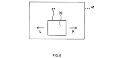
ステップ3では、判断領域決定ユニット11が、判断領域を決定する。この処理を、図4、図6に基づき説明する。図6に示すように、判断領域39とは、前記ステップ1で取得した画像41の一部である。判断領域39は、画像41における下方に位置し、主に路面によって占められる領域である。
In
図4のステップ21では、判断領域39の位置及び大きさを、デフォルトの値とする。判断領域39の位置とは、画像41における相対的な位置である。判断領域39の大きさとは、画像41の大きさに対する相対的な大きさである。メモリ5には、予め、判断領域39のデフォルトの位置及び大きさが記憶されている。
In step 21 of FIG. 4, the position and size of the
ステップ22では、前記ステップ2で取得した舵角情報を用いて、自車両がカーブを走行中であるか否かを判断する。自車両がカーブを走行中であると判断した場合はステップ23に進む。一方、自車両がカーブを走行中ではないと判断した場合は本処理を終了する。この場合、判断領域39の位置及び大きさはデフォルトの値となる。
In step 22, it is determined using the steering angle information acquired in step 2 whether the host vehicle is traveling on a curve. If it is determined that the host vehicle is traveling on a curve, the process proceeds to step 23. On the other hand, if it is determined that the host vehicle is not traveling on the curve, the present process is terminated. In this case, the position and size of the
ステップ23では、前記ステップ2で取得した舵角情報を用いて、自車両が右カーブを走行中であるか否かを判断する。自車両が右カーブを走行中であると判断した場合はステップ24に進む。一方、自車両が右カーブを走行中ではないと判断した場合はステップ25に進む。ステップ25に進む場合は、自車両が左カーブを走行中である場合である。 In step 23, it is determined whether or not the host vehicle is traveling on the right curve using the steering angle information acquired in step 2. If it is determined that the host vehicle is traveling on the right curve, the process proceeds to step 24. On the other hand, if it is determined that the host vehicle is not traveling on the right curve, the process proceeds to step 25. The process proceeds to step 25 when the host vehicle is traveling on the left curve.
ステップ24では、図6に示すように、判断領域39を右方向Rに移動させる。移動量は、舵角が大きいほど大きい。メモリ5には、予め、舵角と移動量との関係を規定するマップが記憶されている。判断領域39の大きさは一定である。なお、ここでは自車両が前進しているとする。自車両が後進している場合は、ステップ24において、判断領域39を左方向Lに移動させる。
In step 24, the
ステップ25では、図6に示すように、判断領域39を左方向Lに移動させる。移動量は、舵角が大きいほど大きい。メモリ5には、予め、舵角と移動量との関係を規定するマップが記憶されている。判断領域39の大きさは一定である。なお、ここでは自車両が前進しているとする。自車両が後進している場合は、ステップ25において、判断領域39を右方向Rに移動させる。
In
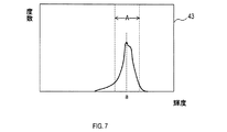
図3に戻り、ステップ4では、輝度取得ユニット15が、前記ステップ3で決定した判断領域39について、図7に示す輝度ヒストグラム43を作成する。この輝度ヒストグラム43の横軸は、輝度である。輝度ヒストグラム43の縦軸は、判断領域39にある全画素のうち、対応する輝度を有する画素の数(以下では度数とする)である。
Returning to FIG. 3, in step 4, the luminance acquisition unit 15 creates the
ステップ5では、輝度取得ユニット15が、前記ステップ4で作成した輝度ヒストグラム43を用いて、輝度aを取得する。輝度aとは、図7に示すように、輝度ヒストグラム43において、度数が最大である輝度である。判断領域39は、主として路面を含む領域であるから、輝度aは、路面を表す画素における最大度数の輝度である。路面に降雪がある場合、輝度aは、路面を覆う雪を表す画素における最大度数の輝度である。
In step 5, the luminance acquisition unit 15 acquires the luminance a using the
ステップ6では、判断領域39におけるコントラストの大きさが、予め設定された閾値以下であるか否かを、視認性判断ユニット12が判断する。その判断方法は以下のとおりである。まず、輝度ヒストグラム43において、輝度aを中心とする範囲であって、判断領域39にある全画素のうち、所定の割合が属する範囲を算出する。次に、その範囲における幅を算出する。算出した幅の値が、閾値より小さければ、コントラストが小さいと判断する。一方、算出した幅の値が、閾値以上であれば、コントラストが大きいと判断する。なお、コントラストが大きいことは視認性が高いことに対応する。
In step 6, the visibility determination unit 12 determines whether or not the magnitude of contrast in the
コントラストが小さいと判断した場合はステップ7に進み、コントラストが大きいと判断した場合はステップ12に進む。
ステップ7では、区分ユニット17が、輝度ヒストグラム43において、領域Aを決定する。領域Aとは、図7に示すように、輝度aを含む輝度の範囲であって、ヒストグラムを表す曲線における傾きの絶対値が、予め設定された閾値より大きい範囲である。領域Aは、主として、路面を表す画素の輝度を含む範囲である。路面に降雪がある場合、領域Aは、主として、路面を覆う雪を表す画素の輝度を含む範囲である。
If it is determined that the contrast is low, the process proceeds to step 7, and if it is determined that the contrast is large, the process proceeds to step 12.
In step 7, the sorting unit 17 determines the area A in the
ステップ8では、区分ユニット17が、まず、前記ステップ1で取得した画像全体について、図8に示す輝度ヒストグラム45を作成する。この輝度ヒストグラム45の横軸は、輝度である。輝度ヒストグラム45の縦軸は、画像全体の画素のうち、対応する輝度を有する画素の度数である。
In step 8, the classification unit 17 first creates a
次に、区分ユニット17は、輝度ヒストグラム45おける輝度範囲を、複数の領域A〜Dに区分する。領域Aは、前記ステップ7で決定した領域である。領域B〜Dは、予め決められたルールに従って区分することができる。領域A〜Dの幅を、それぞれ、幅WA、幅WB、幅WC、幅WDとする。領域B、領域Cは、領域A以外の領域Y1、領域Y2に対応する。領域B、領域Cは領域Aに隣接する。
Next, the dividing unit 17 divides the luminance range in the
ステップ9では、輝度調整ユニット13が、画像の輝度を調整するために用いる補正テーブルを算出する。この処理を、図5、図9、図10に基づき説明する。
図5のステップ31では、天候情報取得ユニット27が、車両信号線35から、天候情報を取得する。
In Step 9, the brightness adjustment unit 13 calculates a correction table used for adjusting the brightness of the image. This process will be described based on FIG. 5, FIG. 9, and FIG.
In step 31 of FIG. 5, the weather information acquisition unit 27 acquires weather information from the
ステップ32では、拡張幅設定ユニット29が、前記ステップ31で取得した天候情報に応じて、領域Aの拡張率RAを決定する。拡張率RAは、以下の式(2)で表される。
式(2) RA=WA’/WA
式(2)においてWA’は、輝度を調整した後における領域Aの幅である。
In
Formula (2) R A = W A ′ / W A
In Formula (2), W A ′ is the width of the region A after adjusting the luminance.
ステップ33では、拡張幅設定ユニット29が、拡張幅ΔAを設定する。拡張幅ΔAとは、輝度の調整において領域Aを拡張する幅である。拡張幅ΔAは、以下の式(3)で表される。 In step 33, the expansion width setting unit 29 sets the expansion width ΔA. The expansion width ΔA is a width for expanding the area A in the luminance adjustment. The expansion width ΔA is expressed by the following formula (3).
式(3) ΔA=WA’−WA=WA(RA−1)
WA、RAはそれぞれ既知の値であるので、ΔAも既知の値である。
ステップ34では、領域調整ユニット19が、輝度ヒストグラム45において、領域Xを検索する。領域Xとは、領域B〜Dのうちのいずれかの領域であって、その領域に属する画素数が予め設定された閾値以下である領域である。本実施形態では、領域Dが領域Xであるとする。
Equation (3) ΔA = W A ' -W A = W A (R A -1)
Since W A and R A are known values, ΔA is also a known value.
In step 34, the area adjustment unit 19 searches for the area X in the
ステップ35では、領域調整ユニット19が、領域Xの幅WXを算出する。本実施形態では、幅WXは、幅WDである。
ステップ36では、前記ステップ33で算出した拡張幅ΔAが、前記ステップ35で算出した幅WXより小さいか否かを、領域調整ユニット19が判断する。拡張幅ΔAが幅WXより小さい場合はステップ37に進む。拡張幅ΔAが幅WX以上である場合はステップ39に進む。
In
In
ステップ37では、領域調整ユニット19が、幅ΔXの値を、前記ステップ33で算出した拡張幅ΔAとする。幅ΔXとは、領域Xにおいて削除する幅である。
ステップ38では、領域調整ユニット19が、第1パターンの補正テーブルを算出する。第1パターンの補正テーブルとは、図9に示すように、画像の輝度を調整する補正テーブルである。第1パターンの補正テーブルでは、領域Xを、幅ΔXだけ削除する。また、領域Aを幅ΔXだけ、領域Xの側に拡張する。拡張後の領域Aの幅WA’は、(WA+ΔX)となる。また、領域Cを、幅ΔXだけ、領域X側に移動させる。領域Cは、領域Aと領域Xとの間に存在する領域である。
In
In step 38, the area adjustment unit 19 calculates a correction table for the first pattern. As shown in FIG. 9, the first pattern correction table is a correction table for adjusting the luminance of an image. In the correction table of the first pattern, the area X is deleted by the width ΔX. Further, the area A is expanded to the area X side by the width ΔX. The width W A ′ of the area A after expansion is (W A + ΔX). Further, the region C is moved to the region X side by the width ΔX. Region C is a region existing between region A and region X.
前記ステップ36で否定判断した場合はステップ39に進む。ステップ39では、領域調整ユニット19が、幅ΔXの値を、幅WXとする。
ステップ40では、領域調整ユニット19が、以下の式(4)で表される幅ΔWBCを算出する。なお、幅ΔWBCは、領域Bにおける縮小幅と、領域Cにおける縮小幅との合計である。なお、縮小とは、圧縮と同義である。
If a negative determination is made in
In
式(4) ΔWBC=ΔA−ΔX
式(4)において、ΔAは前記ステップ33で算出した値であり、ΔXは、前記ステップ39で算出した値である。
Formula (4) ΔW BC = ΔA−ΔX
In Expression (4), ΔA is the value calculated in Step 33, and ΔX is the value calculated in
ステップ41では、領域調整ユニット19が、以下の式(5)、及び式(6)を充足する幅ΔWB、幅ΔWCを算出する。幅ΔWBは、領域Bにおける縮小幅であり、幅ΔWCは、領域Cにおける縮小幅である。式(6)はΔWBとΔWCとの比率を規定する。
In
式(5) ΔWBC=ΔWB+ΔWC
式(6) ΔWB/ΔWC=NB/NC
式(6)において、NBは、画像41の全画素のうち、領域Bに属する画素数であり、NCは、画像41の全画素のうち、領域Cに属する画素数である。ΔWBはΔY1に対応し、ΔWCはΔY2に対応する。
Expression (5) ΔW BC = ΔW B + ΔW C
Equation (6) ΔW B / ΔW C = N B / N C
In Expression (6), N B is the number of pixels belonging to the region B among all the pixels of the
ステップ42では、幅ΔWCが、上限値LCより小さいか否かを領域調整ユニット19が判断する。上限値LCは、領域Cにおける縮小幅の上限値であり、予め定められた値である。幅ΔWCが上限値LCより小さい場合はステップ44に進み、幅ΔWCが上限値LC以上である場合はステップ43に進む。 In step 42, the width [Delta] W C is the upper limit value L C is smaller than whether the area adjustment unit 19 determines. Upper limit L C is the upper limit of the reduced width in the region C, is a predetermined value. Width [Delta] W C proceeds to Step 44 if the upper limit value L C is smaller than the case width [Delta] W C is not less than the upper limit value L C proceeds to step 43.
ステップ43では、領域調整ユニット19が、幅ΔWCの値を、上限値LCに書き換える。また、領域調整ユニット19が、幅ΔWBの値を、ΔWBCから上限値LCを差し引いた値に書き換える。
In
ステップ44では、幅ΔWBが、上限値LBより小さいか否かを領域調整ユニット19が判断する。上限値LBは、領域Bにおける縮小幅の上限値であり、予め定められた値である。幅ΔWBが上限値LCより小さい場合はステップ46に進み、幅ΔWBが上限値LB以上である場合はステップ45に進む。 At step 44, the width [Delta] W B, whether the upper limit value L B smaller area adjusting unit 19 determines. Upper limit L B is the upper limit of the reduced width in the region B, and a predetermined value. Width [Delta] W B is if the upper limit value L C is smaller than the flow proceeds to step 46, if the width [Delta] W B is the upper limit value L B or proceeds to step 45.
ステップ45では、領域調整ユニット19が、幅ΔWBの値を、上限値LBに書き換える。
ステップ46では、領域調整ユニット19が、第2パターンの補正テーブルを算出する。第2パターンの補正テーブルとは、図10に示すように、画像の輝度を調整する補正テーブルである。
In
In
第2パターンの補正テーブルでは、領域Xを全て削除する。また、領域Aを、幅ΔX+幅ΔWCだけ、領域X側に拡張し、幅ΔWBだけ、領域B側に拡張する。領域Aは、全体として、幅ΔX+幅ΔWC+幅ΔWCだけ拡張する。領域Aと領域Bとの境界は、幅ΔWBだけ、領域B側に移動する。領域Bは、幅ΔWBだけ縮小する。領域Aと領域Cとの境界は、幅ΔX+幅ΔWCだけ、領域C側に移動する。領域Cは、幅ΔWCだけ縮小する。幅ΔWB、幅ΔWCの値は、前記ステップ41、43、45のいずれかで設定された値である。上述した幅ΔWB、幅ΔWCの設定方法は、少なくとも拡張幅ΔAに応じた設定方法に対応する。
In the correction table for the second pattern, the entire region X is deleted. Moreover, the region A, the width [Delta] X + width [Delta] W C only extended to region X side, by the width [Delta] W B, extend to the region B side. Area A as a whole expands by width ΔX + width ΔW C + width ΔW C. The boundary between the regions A and B, only the width [Delta] W B, moves in the region B side. The area B is reduced by the width ΔW B. The boundary between the regions A and C, the width [Delta] X + width [Delta] W C only moved to the area C side. Region C is reduced by the width [Delta] W C. The values of the width ΔW B and the width ΔW C are values set in any of the
図3に戻り、ステップ10では、前記ステップ9で算出した補正テーブルに基づき、画像41の輝度を調整する。調整後の画像41における輝度ヒストグラムは、第1パターンの補正テーブル、又は第2パターンの補正テーブルで表されるものになる。なお、輝度を調整した画像41において、領域Aに属する任意の画素の輝度Iは、以下の式(7)で表される。
Returning to FIG. 3, in step 10, the luminance of the
式(7) I=(I0-KAB)×(WA’/WA)+KAB’
式(7)において、I0は、同じ画素の、輝度を調整する前の輝度である。KABは、輝度を調整する前の、領域Aと領域Bとの境界における輝度である。WA’は、輝度を調整した後の、領域Aの幅である。KAB’は、輝度を調整した後の、領域Aと領域Bとの境界における輝度である。
Formula (7) I = (I 0 -K AB ) × (W A ′ / W A ) + K AB ′
In equation (7), I 0 is the luminance of the same pixel before adjusting the luminance. K AB is the luminance at the boundary between the region A and the region B before the luminance is adjusted. W A ′ is the width of the area A after adjusting the luminance. K AB ′ is the luminance at the boundary between the region A and the region B after adjusting the luminance.
ステップ11では、前記ステップ10で輝度を調整した画像をディスプレイ37に出力する。
前記ステップ6で否定判断した場合はステップ12に進む。ステップ12では、前記ステップ1で取得した画像をそのままディスプレイ37に出力する。
3.画像処理装置1が奏する効果
(1A)画像処理装置1は領域Aを拡張する。そのため、領域Aにおけるコントラストを向上させることができる。そのことにより、画像の視認性が向上する。また、拡張幅ΔAのうち、少なくとも一部は、画素数が少ない領域Xを削除して得られるものである。そのため、領域B、領域Cの縮小幅を抑制することができる。その結果、輝度を調整した後でも、画像の画質が劣化しにくい。
In step 11, the image whose luminance has been adjusted in step 10 is output to the
If a negative determination is made in step 6, the process proceeds to step 12. In step 12, the image acquired in step 1 is output to the
3. Effects produced by the image processing apparatus 1 (1A) The image processing apparatus 1 extends the area A. Therefore, the contrast in the region A can be improved. Thereby, the visibility of the image is improved. Further, at least a part of the expansion width ΔA is obtained by deleting the region X having a small number of pixels. For this reason, the reduction width of the region B and the region C can be suppressed. As a result, the image quality is unlikely to deteriorate even after the luminance is adjusted.
(1B)画像処理装置1は、領域Cを領域Xの側に移動させる。そのため、領域Xが領域Aと隣接していない場合でも、領域Aを領域Xの側に拡張することができる。
(1C)画像処理装置1は、領域B、領域Cを縮小し、その縮小した分だけ、さらに領域Aを拡張することができる。その結果、領域Aにおけるコントラストを一層向上させることができる。
(1B) The image processing apparatus 1 moves the region C to the region X side. Therefore, even when the region X is not adjacent to the region A, the region A can be expanded to the region X side.
(1C) The image processing apparatus 1 can reduce the area B and the area C, and can further expand the area A by the reduced amount. As a result, the contrast in the region A can be further improved.
(1D)画像処理装置1は、拡張幅ΔAに応じて、幅ΔWB、幅ΔWCを設定する。そのため、幅ΔWB、幅ΔWCを適切に設定できる。また、画像処理装置1は、幅ΔWB、及び幅ΔWCを、式(5)、式(6)を充足するように設定する。そのため、領域B及び領域Cのうちの一方のみを過度に縮小することを抑制できる。その結果、輝度を調整した後でも、画像の画質が劣化しにくい。 (1D) The image processing apparatus 1 sets the width ΔW B and the width ΔW C according to the expansion width ΔA. Therefore, the width ΔW B and the width ΔW C can be set appropriately. In addition, the image processing apparatus 1 sets the width ΔW B and the width ΔW C so as to satisfy the expressions (5) and (6). Therefore, excessive reduction of only one of the region B and the region C can be suppressed. As a result, the image quality is unlikely to deteriorate even after the luminance is adjusted.
(1E)画像処理装置1は、天候情報を取得し、天候情報に応じて拡張幅ΔAを設定する。そのため、天候に応じて適切な拡張幅ΔAを設定することができる。例えば、降雪があり、領域Aにおけるコントラストが小さい可能性が高い場合は、拡張幅ΔAを大きく設定し、領域Aにおけるコントラストを一層向上させることができる。 (1E) The image processing apparatus 1 acquires weather information and sets the expansion width ΔA according to the weather information. Therefore, an appropriate expansion width ΔA can be set according to the weather. For example, when there is snow and there is a high possibility that the contrast in the region A is small, the expansion width ΔA can be set large to further improve the contrast in the region A.
(1F)画像処理装置1は、幅ΔWBを、上限値LB以下の範囲で設定する。また、画像処理装置1は、幅ΔWCを、上限値LC以下の範囲で設定する。そのことにより、領域B、領域Cを過度に縮小することを抑制できる。その結果、輝度を調整した後でも、画像の画質が劣化しにくい。 (1F) The image processing apparatus 1 sets the width ΔW B within a range equal to or less than the upper limit value L B. The image processing apparatus 1, the width [Delta] W C, set in the range of the upper limit value L C. As a result, excessive reduction of the region B and the region C can be suppressed. As a result, the image quality is unlikely to deteriorate even after the luminance is adjusted.
(1G)画像処理装置1は、舵角情報を取得し、その舵角情報から、自車両が走行中の道路の形状を判断する。さらに、画像処理装置1は、自車両が走行中の道路の形状に応じて判断領域39の位置を決定する。そのことにより、判断領域39の中に路面を含めることができる。また、判断領域39の中に、路面以外の物が含まれることを抑制できる。
<他の実施形態>
以上、本発明を実施するための形態について説明したが、本発明は上述の実施形態に限定されることなく、種々変形して実施することができる。
(1G) The image processing apparatus 1 acquires the steering angle information, and determines the shape of the road on which the host vehicle is traveling from the steering angle information. Furthermore, the image processing apparatus 1 determines the position of the
<Other embodiments>
As mentioned above, although the form for implementing this invention was demonstrated, this invention is not limited to the above-mentioned embodiment, It can implement in various deformation | transformation.
(1)判断領域39の大きさや位置を決定する方法は、他の方法であってもよい。例えば、車両信号線35からソナー情報を取得し、自車両に近づいている物標の有無、及び、物標が自車両に近づいているか、自車両から遠ざかっているかを判断することができる。
(1) The method for determining the size and position of the
自車両が前進しており、物標が存在する場合、以下のように判断領域39を変化させる。
・物標が自車両に近づいていれば、判断領域39における上側の境界線47を、標準の位置より下げる。すなわち、判断領域39を、標準よりも低い範囲に限定する。
When the host vehicle is moving forward and a target is present, the
If the target is approaching the host vehicle, the
・物標が自車両から遠ざかっていれば、上側の境界線47の位置を、標準の位置に戻す。
自車両が後進しており、物標が存在する場合、以下のように判断領域39を変化させる。
If the target is moving away from the host vehicle, the position of the
When the host vehicle is moving backward and a target is present, the
・物標が自車両に近づいていれば、判断領域39における上側の境界線47を、標準の位置より上げる。すなわち、判断領域39を、標準よりも高い範囲まで広げる。
・物標が自車両から遠ざかっていれば、上側の境界線47の位置を、標準の位置に戻す。
If the target is approaching the host vehicle, the
If the target is moving away from the host vehicle, the position of the
(2)判断領域39の大きさや位置を決定する方法は、他の方法であってもよい。例えば、サイドカメラやバックカメラに映っている物標の位置を算出し、その物標を避けるように、判断領域39を設定することができる。
(2) The method for determining the size and position of the
(3)判断領域39の大きさや位置を決定する方法は、他の方法であってもよい。例えば、自車両、又は自車両のタイヤの振動データから路面の状態を推測し、判断領域39の大きさや位置を決定してもよい。路面の状態としては、例えば、積雪の有無等が挙げられる。
(3) The method for determining the size and position of the
(4)判断領域39の大きさや位置は固定されていてもよい。判断領域39の位置は、画像41の中央付近、又は、画像41の上方であってもよい。また、判断領域39の大きさや位置は固定し、判断領域39の形状を、周辺情報に応じて変更してもよい。
(4) The size and position of the
例えば、周辺情報の内容が、自車両の周辺の道路が直線路であるという内容である場合、判断領域39の形状を、台形又は三角形とすることができる。また、周辺情報の内容が、自車両の周辺の道路がカーブであるという内容である場合、判断領域39の形状を、上記の台形又は三角形を変形した形状にすることができる。その変形した形状とは、台形又は三角形の底辺が、カーブの外側方向に延び、カーブの外側の縁、又はその近傍に至っている形状である。また、上記の変形した形状では、カーブの外側の境界線を、カーブの外側に膨らんだ曲線又は折れ線としてもよい。
For example, when the content of the surrounding information is that the road around the host vehicle is a straight road, the shape of the
また、判断領域39の大きさや位置を周辺情報に応じて決定するとともに、判断領域39の形状も、周辺情報に応じて決定してもよい。
(5)拡張幅ΔAが幅WXより小さい場合でも、領域Xの全てを削除してもよい。そして、拡張幅ΔAを、幅WXとすることができる。
Further, the size and position of the
(5) Even when the extension width ΔA is smaller than the width W X , the entire region X may be deleted. Then, the extension width ΔA can be set to the width W X.
(6)領域Aを設定する方法は他の方法であってもよい。例えば、輝度aを中心とし、一定の幅を有する領域を領域Aとしてもよい。
(7)領域A以外の領域の数は適宜設定できる。その数は、例えば、2、4、5、6・・・とすることができる。
(6) The method for setting the region A may be another method. For example, a region having a certain width and centering on the luminance a may be set as the region A.
(7) The number of regions other than region A can be set as appropriate. The number can be, for example, 2, 4, 5, 6,.
(8)領域B、領域Cのうち一方だけを縮小し、他方は縮小しないようにしてもよい。また、領域Aに隣接しない領域が存在する場合は、領域Aに隣接しない領域を縮小してもよい。 (8) Only one of the region B and the region C may be reduced and the other may not be reduced. If there is a region that is not adjacent to the region A, the region that is not adjacent to the region A may be reduced.
(9)領域Bを、上限値LBを超えて縮小するようにしてもよい。また、領域Cを、上限値LCを超えて縮小するようにしてもよい。
(10)判断領域決定ユニット11は、天候情報に応じて判断領域39の位置、大きさ、及び形状から成る群から選択される1以上を決定してもよい。例えば、天候が曇天の場合、それ以外の場合よりも、判断領域39の位置を下げることができる。また、天候が吹雪の場合、それ以外の場合よりも、判断領域39を大きくすることができる。また、天候が雪の場合の判断領域39の形状を、後述するデフォルトの形状より縦長とし、それ以外の場合の形状をデフォルトの形状とすることができる。
(9) a region B, may be reduced by more than the upper limit L B. Also, the region C, may be reduced by more than the upper limit value L C.
(10) The determination area determination unit 11 may determine one or more selected from the group consisting of the position, size, and shape of the
(11)視認性判断ユニット12は、前記ステップ6の処理で使用する閾値を、天候情報に応じて設定することができる。例えば、天候が雨である場合は、それ以外の場合よりも閾値を大きくすることができる。上記の場合、視認性判断ユニット12は、閾値設定ユニットに対応する。 (11) The visibility determination unit 12 can set the threshold value used in the process of step 6 according to the weather information. For example, when the weather is rain, the threshold can be made larger than in other cases. In the above case, the visibility determination unit 12 corresponds to a threshold setting unit.
(12)前記ステップ6において、以下の方法で、判断領域39におけるコントラストの大きさを判断してもよい。なお、コントラストが大きいことは、視認性が高いことに対応する。
(12) In step 6, the magnitude of contrast in the
まず、図11に示すように、輝度ヒストグラム43において、輝度aを中心とする、幅が一定値である範囲Zを設定する。次に、範囲Zにおける平均度数を算出する。平均度数が閾値より大きければ、コントラストが小さいと判断する。一方、平均度数が閾値以下であれば、コントラストが大きいと判断する。
First, as shown in FIG. 11, in the
(13)前記ステップ6において、以下の方法で、判断領域39におけるコントラストの大きさを判断してもよい。なお、コントラストが大きいことは、視認性が高いことに対応する。
(13) In step 6, the magnitude of contrast in the
まず、図11に示すように、輝度ヒストグラム43において、輝度aにおける度数Faを取得する。度数Faが閾値より大きければ、コントラストが小さいと判断する。一方、度数Faが閾値以下であれば、コントラストが大きいと判断する。
First, as shown in FIG. 11, in the
(14)前記ステップ6において、以下の方法で、判断領域39におけるコントラストの大きさを判断してもよい。なお、コントラストが大きいことは、視認性が高いことに対応する。
(14) In step 6, the magnitude of contrast in the
まず、図11に示すように、輝度ヒストグラム43において、範囲Zでのピーク面積Saを算出する。ピーク面積Saが閾値より大きければ、コントラストが小さいと判断する。一方、ピーク面積Saが閾値以下であれば、コントラストが大きいと判断する。
First, as shown in FIG. 11, in the
(15)上記実施形態における1つの構成要素が有する複数の機能を、複数の構成要素によって実現したり、1つの構成要素が有する1つの機能を、複数の構成要素によって実現したりしてもよい。また、複数の構成要素が有する複数の機能を、1つの構成要素によって実現したり、複数の構成要素によって実現される1つの機能を、1つの構成要素によって実現したりしてもよい。また、上記実施形態の構成の一部を省略してもよい。また、上記実施形態の構成の少なくとも一部を、他の上記実施形態の構成に対して付加又は置換してもよい。なお、特許請求の範囲に記載した文言のみによって特定される技術思想に含まれるあらゆる態様が本発明の実施形態である。 (15) A plurality of functions of one constituent element in the above embodiment may be realized by a plurality of constituent elements, or a single function of one constituent element may be realized by a plurality of constituent elements. . Further, a plurality of functions possessed by a plurality of constituent elements may be realized by one constituent element, or one function realized by a plurality of constituent elements may be realized by one constituent element. Moreover, you may abbreviate | omit a part of structure of the said embodiment. In addition, at least a part of the configuration of the above embodiment may be added to or replaced with the configuration of the other embodiment. In addition, all the aspects included in the technical idea specified only by the wording described in the claim are embodiment of this invention.
(16)上述した画像処理装置の他、当該画像処理装置を構成要素とするシステム、当該画像処理装置としてコンピュータを機能させるためのプログラム、このプログラムを記録した半導体メモリ等の非遷移的実態的記録媒体、画像処理方法等、種々の形態で本発明を実現することもできる。 (16) In addition to the image processing apparatus described above, a system including the image processing apparatus as a constituent element, a program for causing a computer to function as the image processing apparatus, and a non-transitional actual recording such as a semiconductor memory storing the program The present invention can also be realized in various forms such as a medium and an image processing method.
1…画像処理装置、3…CPU、5…メモリ、7…画像取得ユニット、9…周辺情報取得ユニット、11…判断領域決定ユニット、12…視認性判断ユニット、13…輝度調整ユニット、15…輝度取得ユニット、17…区分ユニット、19…領域調整ユニット、27…天候情報取得ユニット、29…拡張幅設定ユニット、33…カメラ、35…車両信号線、37…ディスプレイ、39…判断領域、41…画像、43…輝度ヒストグラム、45…輝度ヒストグラム、47…境界線 DESCRIPTION OF SYMBOLS 1 ... Image processing apparatus, 3 ... CPU, 5 ... Memory, 7 ... Image acquisition unit, 9 ... Peripheral information acquisition unit, 11 ... Judgment area determination unit, 12 ... Visibility judgment unit, 13 ... Brightness adjustment unit, 15 ... Luminance Acquisition unit, 17 ... Section unit, 19 ... Region adjustment unit, 27 ... Weather information acquisition unit, 29 ... Expansion width setting unit, 33 ... Camera, 35 ... Vehicle signal line, 37 ... Display, 39 ... Judgment region, 41 ... Image , 43 ... luminance histogram, 45 ... luminance histogram, 47 ... boundary line
Claims (8)
車両の周辺を表す画像を取得する画像取得ユニット(7)と、
前記画像の一部である判断領域(39)において、視認性が予め設定された閾値以下であるか否かを判断する視認性判断ユニット(12)と、
前記視認性が前記閾値以下であると前記視認性判断ユニットが判断した場合、前記画像における輝度を調整する輝度調整ユニット(13)と、
前記車両の周辺における状況を表す周辺情報を取得する周辺情報取得ユニット(9)と、
前記周辺情報に応じて前記判断領域の位置、大きさ、及び形状から成る群から選択される1以上を決定する判断領域決定ユニット(11)と、
を備え、
前記輝度調整ユニットは、
前記判断領域における輝度ヒストグラムにて度数が最大である輝度aを取得する輝度取得ユニット(15)と、
前記画像における輝度範囲を、前記輝度aが属する領域Aを含む複数の領域に区分する区分ユニット(17)と、
複数の前記領域のうち、属する画素数が予め設定された閾値以下である領域Xの少なくとも一部を削除する領域X削除ユニット(19)と、
前記領域Aを、少なくとも、前記領域Xにおいて削除した幅ΔXだけ、前記領域Xの側に拡張する領域A拡張ユニット(19)と、
前記領域Xと前記領域Aとの間に他の前記領域が存在する場合は、他の前記領域を前記領域Xの側に移動させる領域移動ユニット(19)と、
を備える画像処理装置。 An image processing device (1),
An image acquisition unit (7) for acquiring an image representing the periphery of the vehicle;
A visibility determination unit (12) for determining whether or not the visibility is equal to or less than a preset threshold in the determination region (39) which is a part of the image;
A luminance adjustment unit (13) for adjusting luminance in the image when the visibility determination unit determines that the visibility is equal to or less than the threshold;
A peripheral information acquisition unit (9) for acquiring peripheral information representing a situation in the vicinity of the vehicle;
A determination area determination unit (11) that determines one or more selected from the group consisting of the position, size, and shape of the determination area according to the peripheral information;
With
The brightness adjustment unit includes:
A luminance acquisition unit (15) for acquiring the luminance a having the highest frequency in the luminance histogram in the determination area;
A division unit (17) for dividing a luminance range in the image into a plurality of regions including a region A to which the luminance a belongs;
An area X deletion unit (19) that deletes at least a part of the area X in which the number of pixels belonging to the plurality of areas is equal to or less than a preset threshold;
An area A expansion unit (19) for extending the area A to the area X side by at least the width ΔX deleted in the area X;
An area moving unit (19) for moving another area toward the area X when there is another area between the area X and the area A;
An image processing apparatus comprising:
前記周辺情報は、前記車両が走行中である道路の形状を表す情報、又は、前記車両の周辺に存在する物標を表す情報である画像処理装置。 The image processing apparatus according to claim 1 ,
The surrounding information is an image processing apparatus that is information representing a shape of a road on which the vehicle is traveling, or information representing a target existing around the vehicle.
車両の周辺を表す画像を取得する画像取得ユニット(7)と、An image acquisition unit (7) for acquiring an image representing the periphery of the vehicle;
前記画像の一部である判断領域(39)において、視認性が予め設定された閾値以下であるか否かを判断する視認性判断ユニット(12)と、A visibility determination unit (12) for determining whether or not the visibility is equal to or less than a preset threshold in the determination region (39) which is a part of the image;
前記視認性が前記閾値以下であると前記視認性判断ユニットが判断した場合、前記画像における輝度を調整する輝度調整ユニット(13)と、A luminance adjustment unit (13) for adjusting luminance in the image when the visibility determination unit determines that the visibility is equal to or less than the threshold;
天候情報を取得する天候情報取得ユニットと、A weather information acquisition unit for acquiring weather information;
前記天候情報に応じて前記判断領域の位置、大きさ、及び形状から成る群から選択される1以上を決定する判断領域決定ユニット(11)と、A determination area determination unit (11) for determining one or more selected from the group consisting of the position, size, and shape of the determination area according to the weather information;
を備え、With
前記輝度調整ユニットは、The brightness adjustment unit includes:
前記判断領域における輝度ヒストグラムにて度数が最大である輝度aを取得する輝度取得ユニット(15)と、A luminance acquisition unit (15) for acquiring the luminance a having the highest frequency in the luminance histogram in the determination area;
前記画像における輝度範囲を、前記輝度aが属する領域Aを含む複数の領域に区分する区分ユニット(17)と、A division unit (17) for dividing a luminance range in the image into a plurality of regions including a region A to which the luminance a belongs;
複数の前記領域のうち、属する画素数が予め設定された閾値以下である領域Xの少なくとも一部を削除する領域X削除ユニット(19)と、An area X deletion unit (19) that deletes at least a part of the area X in which the number of pixels belonging to the plurality of areas is equal to or less than a preset threshold;
前記領域Aを、少なくとも、前記領域Xにおいて削除した幅ΔXだけ、前記領域Xの側に拡張する領域A拡張ユニット(19)と、An area A expansion unit (19) for extending the area A to the area X side by at least the width ΔX deleted in the area X;
前記領域Xと前記領域Aとの間に他の前記領域が存在する場合は、他の前記領域を前記領域Xの側に移動させる領域移動ユニット(19)と、An area moving unit (19) for moving another area toward the area X when there is another area between the area X and the area A;
を備える画像処理装置。An image processing apparatus comprising:
車両の周辺を表す画像を取得する画像取得ユニット(7)と、An image acquisition unit (7) for acquiring an image representing the periphery of the vehicle;
前記画像の一部である判断領域(39)において、視認性が予め設定された閾値以下であるか否かを判断する視認性判断ユニット(12)と、A visibility determination unit (12) for determining whether or not the visibility is equal to or less than a preset threshold in the determination region (39) which is a part of the image;
前記視認性が前記閾値以下であると前記視認性判断ユニットが判断した場合、前記画像における輝度を調整する輝度調整ユニット(13)と、A luminance adjustment unit (13) for adjusting luminance in the image when the visibility determination unit determines that the visibility is equal to or less than the threshold;
天候情報を取得する天候情報取得ユニットと、A weather information acquisition unit for acquiring weather information;
前記天候情報に応じて前記視認性の判断における前記閾値を設定する閾値設定ユニットと、A threshold setting unit for setting the threshold in the visibility determination according to the weather information;
を備え、With
前記輝度調整ユニットは、The brightness adjustment unit includes:
前記判断領域における輝度ヒストグラムにて度数が最大である輝度aを取得する輝度取得ユニット(15)と、A luminance acquisition unit (15) for acquiring the luminance a having the highest frequency in the luminance histogram in the determination area;
前記画像における輝度範囲を、前記輝度aが属する領域Aを含む複数の領域に区分する区分ユニット(17)と、A division unit (17) for dividing a luminance range in the image into a plurality of regions including a region A to which the luminance a belongs;
複数の前記領域のうち、属する画素数が予め設定された閾値以下である領域Xの少なくとも一部を削除する領域X削除ユニット(19)と、An area X deletion unit (19) that deletes at least a part of the area X in which the number of pixels belonging to the plurality of areas is equal to or less than a preset threshold;
前記領域Aを、少なくとも、前記領域Xにおいて削除した幅ΔXだけ、前記領域Xの側に拡張する領域A拡張ユニット(19)と、An area A expansion unit (19) for extending the area A to the area X side by at least the width ΔX deleted in the area X;
前記領域Xと前記領域Aとの間に他の前記領域が存在する場合は、他の前記領域を前記領域Xの側に移動させる領域移動ユニット(19)と、An area moving unit (19) for moving another area toward the area X when there is another area between the area X and the area A;
を備える画像処理装置。An image processing apparatus comprising:
前記輝度調整ユニットは、複数の前記領域のうち、前記領域A以外の領域である領域Yを幅ΔYだけ縮小する領域Y縮小ユニット(19)をさらに備え、
前記領域A拡張ユニットは、少なくとも、前記幅ΔXと前記幅ΔYとの和だけ前記領域Aを拡張するように構成された画像処理装置。 The image processing apparatus according to any one of claims 1 to 4 , wherein:
The luminance adjustment unit further includes a region Y reduction unit (19) that reduces a region Y other than the region A among the plurality of regions by a width ΔY,
The image processing apparatus configured to expand the area A by at least the sum of the width ΔX and the width ΔY.
少なくとも前記領域Aの拡張幅である拡張幅ΔAに応じて、前記幅ΔYを設定する縮小幅設定ユニット(19)をさらに備える画像処理装置。 The image processing apparatus according to claim 5 ,
An image processing apparatus, further comprising: a reduction width setting unit (19) that sets the width ΔY according to at least an expansion width ΔA that is an expansion width of the region A.
前記領域Y縮小ユニットは、一方の側において前記領域Aに隣接する領域Y1を幅ΔY1だけ縮小するとともに、他方の側において前記領域Aに隣接する領域Y2を幅ΔY2だけ縮小するように構成され、
前記領域A拡張ユニットは、少なくとも、前記幅ΔXと前記幅ΔY1と前記幅ΔY2との和だけ前記領域Aを拡張するように構成され、
前記幅ΔY1と前記幅ΔY2との比率は、以下の式(1)で表される画像処理装置。
式(1) ΔY1/ΔY2=N1/N2
前記N1は前記領域Y1に属する画素数であり、前記N2は前記領域Y2に属する画素数である。 The image processing apparatus according to claim 6 ,
The area Y reduction unit reduces the area Y 1 adjacent to the area A on one side by a width ΔY 1 and reduces the area Y 2 adjacent to the area A on the other side by a width ΔY 2. Composed of
Said region A expansion unit, at least, is configured only to expand the region A sum of the width ΔX and the width [Delta] Y 1 and the width [Delta] Y 2,
The ratio between the width ΔY 1 and the width ΔY 2 is an image processing apparatus represented by the following formula (1).
Formula (1) ΔY 1 / ΔY 2 = N 1 / N 2
N 1 is the number of pixels belonging to the area Y 1 , and N 2 is the number of pixels belonging to the area Y 2 .
前記縮小幅設定ユニットは、予め決められた上限値以下の範囲で、前記幅ΔY1及び前記幅ΔY2を設定するように構成された画像処理装置。 The image processing apparatus according to claim 7 ,
The reduced width setting unit is an image processing apparatus configured to set the width ΔY 1 and the width ΔY 2 within a range equal to or less than a predetermined upper limit value.
Priority Applications (3)
| Application Number | Priority Date | Filing Date | Title |
|---|---|---|---|
| JP2016104488A JP6589741B2 (en) | 2016-05-25 | 2016-05-25 | Image processing device |
| PCT/JP2017/019585 WO2017204304A1 (en) | 2016-05-25 | 2017-05-25 | Image processing device |
| DE112017002664.4T DE112017002664T5 (en) | 2016-05-25 | 2017-05-25 | IMAGING DEVICE |
Applications Claiming Priority (1)
| Application Number | Priority Date | Filing Date | Title |
|---|---|---|---|
| JP2016104488A JP6589741B2 (en) | 2016-05-25 | 2016-05-25 | Image processing device |
Publications (2)
| Publication Number | Publication Date |
|---|---|
| JP2017212597A JP2017212597A (en) | 2017-11-30 |
| JP6589741B2 true JP6589741B2 (en) | 2019-10-16 |
Family
ID=60412387
Family Applications (1)
| Application Number | Title | Priority Date | Filing Date |
|---|---|---|---|
| JP2016104488A Active JP6589741B2 (en) | 2016-05-25 | 2016-05-25 | Image processing device |
Country Status (3)
| Country | Link |
|---|---|
| JP (1) | JP6589741B2 (en) |
| DE (1) | DE112017002664T5 (en) |
| WO (1) | WO2017204304A1 (en) |
Families Citing this family (1)
| Publication number | Priority date | Publication date | Assignee | Title |
|---|---|---|---|---|
| JP7284280B2 (en) * | 2019-09-24 | 2023-05-30 | 株式会社日立国際電気 | surveillance camera system |
Family Cites Families (10)
| Publication number | Priority date | Publication date | Assignee | Title |
|---|---|---|---|---|
| JP2003250042A (en) * | 2002-02-25 | 2003-09-05 | Minolta Co Ltd | Image processing method, image processing apparatus, and digital camera |
| JP2006092168A (en) * | 2004-09-22 | 2006-04-06 | Konica Minolta Photo Imaging Inc | Image processing method, image processor and picture processing program |
| JP2008172677A (en) * | 2007-01-15 | 2008-07-24 | Murata Mach Ltd | Image processor and ground color detection method |
| JP2011228857A (en) * | 2010-04-16 | 2011-11-10 | Clarion Co Ltd | Calibration device for on-vehicle camera |
| JP5423631B2 (en) * | 2010-09-24 | 2014-02-19 | 株式会社デンソー | Image recognition device |
| JP5435307B2 (en) | 2011-06-16 | 2014-03-05 | アイシン精機株式会社 | In-vehicle camera device |
| CN103188433B (en) * | 2011-12-30 | 2016-01-20 | 株式会社日立制作所 | Image demister and image haze removal method |
| JP2013186872A (en) * | 2012-03-12 | 2013-09-19 | Mitsubishi Electric Corp | Operation support device |
| JP6329438B2 (en) * | 2014-06-12 | 2018-05-23 | 株式会社Subaru | Outside environment recognition device |
| JP6146499B2 (en) | 2016-03-02 | 2017-06-14 | 栗田工業株式会社 | Treatment of ammonia-containing wastewater |
-
2016
- 2016-05-25 JP JP2016104488A patent/JP6589741B2/en active Active
-
2017
- 2017-05-25 WO PCT/JP2017/019585 patent/WO2017204304A1/en active Application Filing
- 2017-05-25 DE DE112017002664.4T patent/DE112017002664T5/en active Pending
Also Published As
| Publication number | Publication date |
|---|---|
| JP2017212597A (en) | 2017-11-30 |
| DE112017002664T5 (en) | 2019-03-14 |
| WO2017204304A1 (en) | 2017-11-30 |
Similar Documents
| Publication | Publication Date | Title |
|---|---|---|
| JP6323018B2 (en) | Driving assistance device | |
| JP4584120B2 (en) | Road marking line detection device, road marking line detection method, road marking line detection program | |
| US10315570B2 (en) | Image processing apparatus and image processing method | |
| US20150367781A1 (en) | Lane boundary estimation device and lane boundary estimation method | |
| JP2014115978A (en) | Mobile object recognition device, notification apparatus using the device, mobile object recognition program for use in the mobile object recognition device, and mobile object with the mobile object recognition device | |
| JP2015219773A (en) | Object detection device, driving support device, object detection method, and object detection program | |
| US11270133B2 (en) | Object detection device, object detection method, and computer-readable recording medium | |
| JP6711395B2 (en) | Image processing device, imaging device, mobile device control system, mobile device, image processing method, and program | |
| JP5966513B2 (en) | Rear side photographing device for vehicle | |
| JP2006318272A (en) | Vehicular object detection device and method | |
| JP5262515B2 (en) | Vehicle display device and display method | |
| JP6589741B2 (en) | Image processing device | |
| JP6152261B2 (en) | Car parking frame recognition device | |
| WO2019034916A1 (en) | System and method for presentation and control of virtual camera image for a vehicle | |
| CN115147580A (en) | Image processing apparatus, image processing method, mobile apparatus, and storage medium | |
| JP2013186872A (en) | Operation support device | |
| JP2013160895A (en) | Camera exposure setting device | |
| US20140316659A1 (en) | Airbag control apparatus and method for controlling airbag device of vehicle | |
| JP5235843B2 (en) | Vehicle periphery monitoring device and vehicle periphery monitoring method | |
| WO2019155868A1 (en) | Image generation device and image generation method | |
| JP5919988B2 (en) | Image processing device | |
| JP6785172B2 (en) | Vehicle image display device | |
| KR101759270B1 (en) | Apparatus and method for detecting vehicle candidate | |
| JP7354773B2 (en) | Object detection device, object detection method, and object detection program | |
| KR101628931B1 (en) | Method and apparatus for controlling view angle of blackbox |
Legal Events
| Date | Code | Title | Description |
|---|---|---|---|
| A621 | Written request for application examination |
Free format text: JAPANESE INTERMEDIATE CODE: A621 Effective date: 20180507 |
|
| A131 | Notification of reasons for refusal |
Free format text: JAPANESE INTERMEDIATE CODE: A131 Effective date: 20190514 |
|
| A521 | Request for written amendment filed |
Free format text: JAPANESE INTERMEDIATE CODE: A523 Effective date: 20190606 |
|
| TRDD | Decision of grant or rejection written | ||
| A01 | Written decision to grant a patent or to grant a registration (utility model) |
Free format text: JAPANESE INTERMEDIATE CODE: A01 Effective date: 20190820 |
|
| A61 | First payment of annual fees (during grant procedure) |
Free format text: JAPANESE INTERMEDIATE CODE: A61 Effective date: 20190902 |
|
| R151 | Written notification of patent or utility model registration |
Ref document number: 6589741 Country of ref document: JP Free format text: JAPANESE INTERMEDIATE CODE: R151 |
|
| R250 | Receipt of annual fees |
Free format text: JAPANESE INTERMEDIATE CODE: R250 |
|
| R250 | Receipt of annual fees |
Free format text: JAPANESE INTERMEDIATE CODE: R250 |