JP6587681B2 - Temperature compensated beam resonator - Google Patents
Temperature compensated beam resonator Download PDFInfo
- Publication number
- JP6587681B2 JP6587681B2 JP2017517781A JP2017517781A JP6587681B2 JP 6587681 B2 JP6587681 B2 JP 6587681B2 JP 2017517781 A JP2017517781 A JP 2017517781A JP 2017517781 A JP2017517781 A JP 2017517781A JP 6587681 B2 JP6587681 B2 JP 6587681B2
- Authority
- JP
- Japan
- Prior art keywords
- resonator
- mode
- resonator device
- tcf
- beams
- Prior art date
- Legal status (The legal status is an assumption and is not a legal conclusion. Google has not performed a legal analysis and makes no representation as to the accuracy of the status listed.)
- Active
Links
- 239000013078 crystal Substances 0.000 claims description 35
- 238000005452 bending Methods 0.000 claims description 27
- XUIMIQQOPSSXEZ-UHFFFAOYSA-N Silicon Chemical compound [Si] XUIMIQQOPSSXEZ-UHFFFAOYSA-N 0.000 claims description 25
- 229910052710 silicon Inorganic materials 0.000 claims description 25
- 239000010703 silicon Substances 0.000 claims description 25
- 239000002019 doping agent Substances 0.000 claims description 12
- 230000008602 contraction Effects 0.000 claims description 9
- 239000004065 semiconductor Substances 0.000 claims description 3
- 239000003795 chemical substances by application Substances 0.000 claims 1
- 235000012431 wafers Nutrition 0.000 description 25
- 230000001419 dependent effect Effects 0.000 description 8
- 230000003071 parasitic effect Effects 0.000 description 6
- 230000007423 decrease Effects 0.000 description 5
- 238000000034 method Methods 0.000 description 5
- 239000010410 layer Substances 0.000 description 4
- 239000000463 material Substances 0.000 description 4
- 238000004519 manufacturing process Methods 0.000 description 3
- 239000000758 substrate Substances 0.000 description 3
- 238000005259 measurement Methods 0.000 description 2
- 230000000284 resting effect Effects 0.000 description 2
- 239000000725 suspension Substances 0.000 description 2
- PIGFYZPCRLYGLF-UHFFFAOYSA-N Aluminum nitride Chemical compound [Al]#N PIGFYZPCRLYGLF-UHFFFAOYSA-N 0.000 description 1
- 102100022057 Hepatocyte nuclear factor 1-alpha Human genes 0.000 description 1
- 101001045751 Homo sapiens Hepatocyte nuclear factor 1-alpha Proteins 0.000 description 1
- ZOKXTWBITQBERF-UHFFFAOYSA-N Molybdenum Chemical compound [Mo] ZOKXTWBITQBERF-UHFFFAOYSA-N 0.000 description 1
- OAICVXFJPJFONN-UHFFFAOYSA-N Phosphorus Chemical compound [P] OAICVXFJPJFONN-UHFFFAOYSA-N 0.000 description 1
- 229910052787 antimony Inorganic materials 0.000 description 1
- WATWJIUSRGPENY-UHFFFAOYSA-N antimony atom Chemical compound [Sb] WATWJIUSRGPENY-UHFFFAOYSA-N 0.000 description 1
- 229910052785 arsenic Inorganic materials 0.000 description 1
- RQNWIZPPADIBDY-UHFFFAOYSA-N arsenic atom Chemical compound [As] RQNWIZPPADIBDY-UHFFFAOYSA-N 0.000 description 1
- 230000008878 coupling Effects 0.000 description 1
- 238000010168 coupling process Methods 0.000 description 1
- 238000005859 coupling reaction Methods 0.000 description 1
- 230000000694 effects Effects 0.000 description 1
- 230000014509 gene expression Effects 0.000 description 1
- 239000011159 matrix material Substances 0.000 description 1
- 229910052751 metal Inorganic materials 0.000 description 1
- 239000002184 metal Substances 0.000 description 1
- 229910052750 molybdenum Inorganic materials 0.000 description 1
- 239000011733 molybdenum Substances 0.000 description 1
- 230000000737 periodic effect Effects 0.000 description 1
- 229910052698 phosphorus Inorganic materials 0.000 description 1
- 239000011574 phosphorus Substances 0.000 description 1
- 239000010453 quartz Substances 0.000 description 1
- VYPSYNLAJGMNEJ-UHFFFAOYSA-N silicon dioxide Inorganic materials O=[Si]=O VYPSYNLAJGMNEJ-UHFFFAOYSA-N 0.000 description 1
- 239000002356 single layer Substances 0.000 description 1
- 230000007306 turnover Effects 0.000 description 1
Images


Classifications
-
- H—ELECTRICITY
- H03—ELECTRONIC CIRCUITRY
- H03H—IMPEDANCE NETWORKS, e.g. RESONANT CIRCUITS; RESONATORS
- H03H9/00—Networks comprising electromechanical or electro-acoustic devices; Electromechanical resonators
- H03H9/02—Details
- H03H9/02244—Details of microelectro-mechanical resonators
- H03H9/02433—Means for compensation or elimination of undesired effects
- H03H9/02448—Means for compensation or elimination of undesired effects of temperature influence
-
- H—ELECTRICITY
- H03—ELECTRONIC CIRCUITRY
- H03H—IMPEDANCE NETWORKS, e.g. RESONANT CIRCUITS; RESONATORS
- H03H9/00—Networks comprising electromechanical or electro-acoustic devices; Electromechanical resonators
- H03H9/24—Constructional features of resonators of material which is not piezoelectric, electrostrictive, or magnetostrictive
- H03H9/2405—Constructional features of resonators of material which is not piezoelectric, electrostrictive, or magnetostrictive of microelectro-mechanical resonators
- H03H9/2447—Beam resonators
-
- H—ELECTRICITY
- H03—ELECTRONIC CIRCUITRY
- H03H—IMPEDANCE NETWORKS, e.g. RESONANT CIRCUITS; RESONATORS
- H03H9/00—Networks comprising electromechanical or electro-acoustic devices; Electromechanical resonators
- H03H9/24—Constructional features of resonators of material which is not piezoelectric, electrostrictive, or magnetostrictive
- H03H9/2405—Constructional features of resonators of material which is not piezoelectric, electrostrictive, or magnetostrictive of microelectro-mechanical resonators
- H03H2009/241—Bulk-mode MEMS resonators
-
- H—ELECTRICITY
- H03—ELECTRONIC CIRCUITRY
- H03H—IMPEDANCE NETWORKS, e.g. RESONANT CIRCUITS; RESONATORS
- H03H3/00—Apparatus or processes specially adapted for the manufacture of impedance networks, resonating circuits, resonators
- H03H3/007—Apparatus or processes specially adapted for the manufacture of impedance networks, resonating circuits, resonators for the manufacture of electromechanical resonators or networks
- H03H3/0072—Apparatus or processes specially adapted for the manufacture of impedance networks, resonating circuits, resonators for the manufacture of electromechanical resonators or networks of microelectro-mechanical resonators or networks
- H03H3/0076—Apparatus or processes specially adapted for the manufacture of impedance networks, resonating circuits, resonators for the manufacture of electromechanical resonators or networks of microelectro-mechanical resonators or networks for obtaining desired frequency or temperature coefficients
Landscapes
- Physics & Mathematics (AREA)
- Acoustics & Sound (AREA)
- Engineering & Computer Science (AREA)
- Manufacturing & Machinery (AREA)
- Piezo-Electric Or Mechanical Vibrators, Or Delay Or Filter Circuits (AREA)
- Micromachines (AREA)
Description
本発明はマイクロ電気機械共振器に関する。特に、本発明はビームを含む共振器の周波数温度係数(TCF)の調整に関する。 The present invention relates to a microelectromechanical resonator. In particular, the present invention relates to adjusting the frequency temperature coefficient (TCF) of a resonator that includes a beam.
広く使用されている水晶ベース共振器は、多くの分野でマイクロ機械共振器、一般的にはシリコンベース共振器、と置き換えられる可能性がある。シリコン共振器は水晶共振器より小さくでき、シリコン共振器には複数の標準的な製造方法がある。しかしながら、シリコンベース共振器と関連する問題として、これらの共振器は共振周波数の温度ドリフトが高いという問題を有する。このドリフトは、主にシリコンのヤング率の温度依存性に起因し、約−30ppm/Cの周波数温度係数(TCF)を生じる。これは周囲温度の変化により共振周波数の変動をもたらす。 Widely used crystal-based resonators can be replaced in many fields by micromechanical resonators, typically silicon-based resonators. Silicon resonators can be smaller than quartz resonators, and there are several standard manufacturing methods for silicon resonators. However, as a problem associated with silicon-based resonators, these resonators have the problem of high resonant frequency temperature drift. This drift is mainly due to the temperature dependence of the Young's modulus of silicon and produces a frequency temperature coefficient (TCF) of about −30 ppm / C. This results in fluctuations in the resonant frequency due to changes in ambient temperature.
TCFに関しては、線形、即ち一次の挙動と二次の挙動の両方が実際上重要であり、その理由は、第1の挙動は温度変化による周波数の局部的変化(理想的にはゼロ)を表し、周波数対温度曲線の曲率を記述する第2の挙動は低いドリフト温度範囲の幅を表す。一次項がゼロであれば、周波数ドリフトは二次項のみから生じ、TCFがその絶対最小値になる特定の「ターンオーバ温度」が存在する。二次TCFはここでは、一次係数TCF1(線形TCF)と対比してTCF2ともいう。ATカット水晶は25℃においてほぼゼロの低いTCF1及びTCF2を有し、それらの総合周波数ドリフトは一般的には−40℃〜+85℃の広い温度範囲(所謂工業範囲)に亘って±10ppm以内である。シリコン共振器の温度性能は現時点ではかなり悪い。 With respect to TCF, both linear, i.e., first and second order behavior are practically important because the first behavior represents a local change in frequency (ideally zero) due to temperature changes. The second behavior describing the curvature of the frequency versus temperature curve represents the width of the low drift temperature range. If the first order term is zero, then the frequency drift comes from only the second order term and there is a specific “turnover temperature” at which TCF becomes its absolute minimum. The secondary TCF is also referred to herein as TCF 2 in contrast to the primary coefficient TCF 1 (linear TCF). AT cut crystals have low TCF 1 and TCF 2 of nearly zero at 25 ° C., and their overall frequency drift is typically ± 10 ppm over a wide temperature range (so-called industrial range) of −40 ° C. to + 85 ° C. Is within. The temperature performance of silicon resonators is currently quite bad.
温度ドリフトの問題を除去又は緩和する一つの有望な方法は極度に高濃度のシリコンドーピングである。バルク弾性波(BAW)共振挙動への1019cm−3より高濃度の均一なn型ドーピングの効果は、例えば国際公開WO2012/110708号明細書(特許文献1)において検討されている。この特許文献は、「純粋」c11−c12モード(c11,c12及びc44はシリコンのヤング率の弾性項である)のTCF1はゼロより十分上にとどまり、周波数は依然として温度に大きく依存する。しかしながら、面積伸縮(SE)モード又は幅伸縮(WE)モード等の他のBAW共振モードはそのような弾性パラメータc11,c12(及びc44)への依存性を有するため、線形TCFをそれらの面内幾何学的アスペクト比の正しい選択によってゼロにすることができる。 One promising way to eliminate or mitigate the problem of temperature drift is extremely high silicon doping. The effect of uniform n-type doping at a concentration higher than 10 19 cm −3 on the bulk acoustic wave (BAW) resonance behavior is studied, for example, in International Publication WO2012 / 110708 (Patent Document 1). This patent document shows that the TCF 1 of the “pure” c 11 -c 12 mode (c 11 , c 12 and c 44 are elastic terms of the Young's modulus of silicon) stays well above zero and the frequency is still at temperature. It depends heavily. However, other BAW resonance modes, such as area stretch (SE) mode or width stretch (WE) mode, have a dependency on such elastic parameters c 11 , c 12 (and c 44 ), so linear TCFs are Can be zeroed by the correct choice of the in-plane geometric aspect ratio.
ビーム共振器に関して、特許文献1に、例えば、nドーパント濃度が1.6*1019〜5*1019cm-3の範囲内にあり、ウェハ面内の回転角が(100)又は(110)面内の[100]結晶方向から0〜25度の範囲内である場合に、ビーム共振器の一次TCFは伸縮モード及び屈曲モードにおいて最小になることが教示されている。従って、これらの範囲内に、周波数の温度ドリフトを生じない単一の温度点が存在する。しかしながら、特許文献1はもっと広い安定動作温度範囲を達成する方法、即ち二次TCFを最小にする方法を教示していない。また、Jaakkola et al, "Determination of Doping and Temperature Dependent Elastic Constants of Degenerately Doped Silicon from MEMS Resonators ", IEEE Transactions on Ultrasonics, Ferroelectrics, and Frequency Control Vol. 61, No. 7, pp 1063-1074, July 2014(非特許文献1)は、少なくともラーメプレート共振器及び長さ伸縮ビーム共振器は2*1019cm−3より大きいnドーピングレベルで有効に一次温度補償され得ることを示唆し、示している。
Regarding the beam resonator, in
別の方法は、米国特許第8558643号明細書(特許文献2)で検討されているように、異なるドーピングレベル又は結晶方向を有する重畳層を備えた有効材料構造を形成する。この構造は、アンドープ又は均一ドープの対応シリコン元素より低いTCFを有する共振モードを実行し得る超格子を形成する。このような構造は、100℃の範囲に亘って50ppmより低い温度ドリフトが達成されるように、二次TCFをある程度減少させるために使用することもできる。 Another method forms an effective material structure with overlapping layers having different doping levels or crystal orientations, as discussed in US Pat. No. 8,558,643. This structure forms a superlattice that can perform a resonant mode with a TCF lower than the corresponding undoped or uniformly doped silicon element. Such a structure can also be used to reduce the secondary TCF to some extent so that a temperature drift below 50 ppm is achieved over the 100 ° C. range.
上述の文献はシリコンドーピングを利用する他の文献も援用し、温度ドリフト問題に対処する他の方法も検討している。 The above references also incorporate other references that utilize silicon doping, and other ways to address the temperature drift problem are also being considered.
共振器の温度挙動はドーピング濃度に依存するのみならず、その幾何学的形状、結晶方向及びそこで励起される共振モードにも依存し、いくつかの重要な因子に言及する。さらに、考慮する必要がある因子は、共振器のQ値(共振器の固定法が重要な役割を果たす)と、共振器設計を実際に製造する能力である。低いTCFと高いQ値は、例えば一般的に種々の幾何学的レイアウトで達成されるため、既知の共振器設計において相反する設計目標になり得る。 The temperature behavior of the resonator depends not only on the doping concentration, but also on its geometry, crystal orientation and the resonant mode excited there, and mentions several important factors. Further factors that need to be considered are the resonator Q-factor (the way in which the resonator is fixed plays an important role) and the ability to actually manufacture the resonator design. Low TCF and high Q values can be conflicting design goals in known resonator designs, for example, since they are typically achieved with various geometric layouts.
現時点で実際に実現可能で利用可能な低TCFシリコン共振器の設計は少なく、そのいくつかが特許文献1及び特許文献2に開示されているにすぎない。しかしながら、TCF特性と高いQ値を同時により良好に制御し得るように改良された実際に実現可能な新設計が必要とされている。 At present, there are few designs of low TCF silicon resonators that can be actually realized and used, and some of them are disclosed in US Pat. However, there is a need for a new, practically feasible design that is improved to better control the TCF characteristics and high Q value simultaneously.
本発明の目的は、変化する温度において高い安定動作周波数を有する共振器装置を提供することにある。特に、一次及び二次TCFの小さい共振器を提供することを目的とする。 An object of the present invention is to provide a resonator device having a high stable operating frequency at varying temperatures. In particular, an object is to provide a resonator having a small primary and secondary TCF.
本発明は、相対的に高濃度にドープされたn型半導体ウェハ上に、一般的にウェハ面内で結晶格子に対して傾けたビーム形の共振器素子を製造することに基づいている。傾けたビーム共振器の一次TCFはゼロにできることが知られているが、今回、ある限度内で一次及び二次TCFが特定の共振モードにおいて同時にゼロになるドーピングレベルと傾きの組み合わせが存在することが分かった。 The present invention is based on fabricating a beam-shaped resonator element, generally tilted with respect to a crystal lattice in the wafer plane, on a relatively heavily doped n-type semiconductor wafer. It is known that the primary TCF of a tilted beam resonator can be zero, but this time there exists a combination of doping level and tilt within which certain primary and secondary TCFs are zero simultaneously in a particular resonant mode. I understood.
従って、本発明は、支持構造と、(100)又は(110)半導体ウェハ上に製造された共振器とを備えるマイクロ電気機械共振器を提供し、前記共振器は前記支持構造に懸架され、1.1*1020cm−3又はそれ以上のドーピング濃度にn型ドーピング剤がドープされ且つ適切な駆動時に長さ伸縮、屈曲又はねじれモードで共振し得る少なくとも一つのビームを備える。特に、前記ビームのドーピング濃度及び角度は、前記共振モードにおいて、ゼロ又はゼロに近い二次TCFを、より好ましくはゼロ又はゼロに近い一次及び二次TCFを同時に生じるように選択される。 Accordingly, the present invention provides a microelectromechanical resonator comprising a support structure and a resonator fabricated on a (100) or (110) semiconductor wafer, the resonator being suspended from the support structure, .1 * 10 20 cm −3 or more doped with an n-type dopant and comprising at least one beam that can resonate in length-stretching, bending or torsional modes when properly driven. In particular, the doping concentration and angle of the beam are selected to simultaneously produce zero or near zero secondary TCF, more preferably zero or near zero primary and secondary TCF in the resonant mode.
一態様によれば、関連する共振モードは屈曲又は長さ伸縮モードであり、ビームの長手方向軸は[100]結晶方向に対して17±10度の角度に向けられる。これは一次以上の屈曲モード及び一次以上の長さ伸縮モードに対する両TCF1及びTCF2の受動的なゼロ化を可能にする。 According to one aspect, the associated resonant mode is a bending or length stretching mode and the longitudinal axis of the beam is oriented at an angle of 17 ± 10 degrees relative to the [100] crystal direction. This allows passive zeroing of both TCF 1 and TCF 2 for first-order or higher bending modes and first- or higher-length stretch modes.
別の態様によれば、関連する共振モードはねじれモードであり、ビームの長手方向軸は[110]結晶方向に対して0±35度の角度に向けられる。これは一次以上のねじれモードに対する両TCF1及びTCF2の受動的なゼロ化を可能にする。前記角度は例えば±5...35度とする、即ち[110]方向に対して適度に傾けることができる。一実施形態では、ビームの面外アスペクト比を所定の角度に対して両TCF1及びTCF2が最小になるように選択する。このアスペクト比は例えば2未満、特に1.5未満にし得る。特に、(110)面内のねじれビームに対して、面外アスペクト比は1.3未満、例えば0.1...1.2に、(100)面内のねじれビームに対して、面外アスペクト比は1未満、例えば0.1...0.9にし得る。後者の場合には、TCF1及びTCF2の両方がゼロになる角度範囲が幾分小さくなり、即ち0±20度になる。 According to another aspect, the associated resonant mode is a torsional mode and the longitudinal axis of the beam is oriented at an angle of 0 ± 35 degrees relative to the [110] crystal direction. This allows passive zeroing of both TCF 1 and TCF 2 for first and higher order torsional modes. The angle is, for example, ± 5. . . The angle can be set to 35 degrees, that is, it can be appropriately inclined with respect to the [110] direction. In one embodiment, the out-of-plane aspect ratio of the beam is selected so that both TCF 1 and TCF 2 are minimized for a given angle. This aspect ratio can be, for example, less than 2, in particular less than 1.5. In particular, for torsional beams in the (110) plane, the out-of-plane aspect ratio is less than 1.3, for example 0.1. . . 1.2, for torsional beams in the (100) plane, the out-of-plane aspect ratio is less than 1, for example 0.1. . . Can be 0.9. In the latter case, the angular range where both TCF 1 and TCF 2 are zero is somewhat smaller, ie 0 ± 20 degrees.
より具体的には、本発明は従属請求項に記載の事項で特徴付けられる。 More specifically, the invention is characterized by what is stated in the dependent claims.
特に、ドーピング濃度、ビーム方向及び共振モードは、少なくとも一つの温度において共振器の一次周波数温度係数(TCF1)が1ppm/C又はそれ以下になるとともに、二次周波数温度係数(TCF2)が12ppb/C2又はそれ以下になるように、上述した範囲内で選択される。前記少なくとも一つの温度は、工業温度範囲(−40...85℃)のほぼ中央値を示す25℃であり、周波数変化対温度曲線の頂点が位置する温度に相当する。12ppb/C2又はそれ以下の二次周波数ドリフトは工業範囲に亘って約50ppm又はそれ以下の総合周波数ドリフトに相当する。 In particular, the doping concentration, beam direction, and resonance mode have a primary frequency temperature coefficient (TCF 1 ) of the resonator of 1 ppm / C or lower and a secondary frequency temperature coefficient (TCF 2 ) of 12 ppb at at least one temperature. / C 2 or less is selected within the above-described range. Said at least one temperature is 25 ° C., which is approximately the median of the industrial temperature range (−40... 85 ° C.), and corresponds to the temperature at which the peak of the frequency change vs. temperature curve is located. A secondary frequency drift of 12 ppb / C 2 or less corresponds to an overall frequency drift of about 50 ppm or less over the industrial range.
特に、TCF2は少なくとも一つの温度において6ppb/C2又はそれ以下(絶対値)及びさらに3ppb/C2又はそれ以下にすることができ、工業範囲に亘ってそれぞれ25ppm及び12ppmの総合周波数ドリフトに相当する。 In particular, TCF 2 can be 6 ppb / C 2 or less (absolute value) and even 3 ppb / C 2 or less at at least one temperature, resulting in an overall frequency drift of 25 ppm and 12 ppm, respectively, over the industrial range. Equivalent to.
TCF1は、好ましくは0.5ppm/C又はそれ以下とする。 TCF1 is preferably 0.5 ppm / C or less.
本共振器のビーム部分は基板及び/又は隣接ビーム又は共振器の他の素子部分にその中心、一以上の端から又は外周の一以上の他の点から取り付けられた屈曲、ねじれ又は長さ伸縮ばね素子とすることができる。屈曲又は長さ伸縮モードの場合には、ビームは傾ける必要があるが、ねじれモードの場合には、非傾斜ビームに対してTCF1=TCF2=0の特定のビーム断面幾何形状も存在する。本発明は単一のビーム共振器に限定されず、2以上のこのようなビームを備える共振器も包含する。ビーム形でない又はビーム形であるが上述した角度範囲に向けられていない共振器の他の要素も存在し得る。いくつかの実用的な幾何学的構成が本明細書において後に例示される。 The beam portion of the resonator is bent, twisted or stretched at its center, from one or more ends, or from one or more other points on the periphery to the substrate and / or adjacent beam or other element portion of the resonator. It can be a spring element. The beam needs to be tilted in the bending or lengthening / contracting mode, but there is also a specific beam cross-section geometry of TCF 1 = TCF 2 = 0 for the non-tilted beam in the torsional mode. The invention is not limited to a single beam resonator, but also encompasses a resonator comprising two or more such beams. There may also be other elements of the resonator that are not beam-shaped or beam-shaped but not directed to the angular range described above. Several practical geometric configurations are exemplified later in this specification.
本発明は大きな利点をもたらす。なによりもまず、開示のドーピング濃度及びビーム方向の範囲内では、二次TCF及び必要に応じ一次TCFも開示の共振モードの一つにおいてゼロ又はほぼゼロになる。したがって、共振器は変化する温度において高い周波数安定性を有する。 The present invention provides significant advantages. First of all, within the disclosed doping concentration and beam direction range, the secondary TCF and optionally the primary TCF are also zero or nearly zero in one of the disclosed resonant modes. Thus, the resonator has a high frequency stability at varying temperatures.
実際的見地から、非線形の周波数挙動は線形挙動よりも例えば能動的な補償を用いて補償することが難しいため、TCF2の受動的なゼロ化は極めて重要である。 From a practical point of view, passive zeroing of TCF 2 is extremely important because nonlinear frequency behavior is more difficult to compensate, eg, with active compensation than linear behavior.
一次及び二次TCFは比較的容易に別々にゼロにすることができるが、本明細書で検討されている特定の共振モードにおけるそれらの同時ゼロ化は本明細書に開示される特定の幾何学的構成及び比較的に狭いパラメータ範囲でのみ生じる。TCF1及びTCF2の同時ゼロ化に関して文献には明確な教示は何もないが、このことは本発明の重要な特徴である。 Although primary and secondary TCFs can be zeroed separately with relative ease, their simultaneous zeroing in the particular resonant modes discussed herein is not limited to the particular geometry disclosed herein. Occurs only in a typical configuration and in a relatively narrow parameter range. Although there is no clear teaching in the literature regarding the simultaneous zeroing of TCF 1 and TCF 2 , this is an important feature of the present invention.
本発明は、実際に証明可能に達成可能なn型ドーピング濃度を用いて実現可能である。互いに積み重ねられた異なる層内に異なる材料特性を有する超格子構造と比較して、本共振器素子はモノリシック単層素子として製造でき、よってその製造は簡単である。また、必要とされるドーパント濃度も超格子実装の場合に必要とされるものより小さい。また、本共振器は本質的に所要の周波数安定度を満たすように設計されているので、共振器の周囲の複雑な能動温度補償回路を不要にし得る。 The present invention can be implemented using n-type doping concentrations that can be achieved in practice. Compared to superlattice structures with different material properties in different layers stacked on top of each other, the resonator element can be manufactured as a monolithic single layer element and is therefore simple to manufacture. Also, the required dopant concentration is less than that required for superlattice mounting. In addition, since the resonator is designed to satisfy the required frequency stability, a complicated active temperature compensation circuit around the resonator can be dispensed with.
従属請求項は本発明の選ばれた実施形態に向けられている。 The dependent claims are directed to selected embodiments of the present invention.
一実施形態によれば、共振器はただ一つのビームを備える。このビームは上述したように方向づけられ、ドープされ、共振するように構成される。本共振器は本質的にこのビームからなるものとしてもよく、よってこのビームは共振器装置の唯一の共振素子として支持構造に直接懸架される。これは恐らく、一次及び二次TCFをゼロにし得る本発明の最も簡単な実施形態である。 According to one embodiment, the resonator comprises only one beam. This beam is directed, doped and configured to resonate as described above. The resonator may consist essentially of this beam, so that this beam is suspended directly on the support structure as the only resonant element of the resonator device. This is probably the simplest embodiment of the present invention where the primary and secondary TCF can be zero.
代替実施形態によれば、共振器は上述したように方向づけられ、ドープされ、共振するように構成された少なくとも2つのビームを備える。これらのビームは、所謂「傾斜チューニングフォーク」のように平行にしても、代わりに、所謂「対称化チューニングフォーク」のように非平行、即ち互いに非ゼロ角度にしてもよい。実際上、本発明は構造全体を結晶格子に対して対称にすることができ、よって共振器の寄生共振を回避し、共振器のQを改善することができる。 According to an alternative embodiment, the resonator comprises at least two beams that are oriented, doped and configured to resonate as described above. These beams may be parallel as in a so-called “tilted tuning fork”, or alternatively non-parallel, ie at non-zero angles with respect to each other, as in a so-called “symmetrized tuning fork”. In practice, the present invention can make the entire structure symmetric with respect to the crystal lattice, thus avoiding parasitic resonance of the resonator and improving the Q of the resonator.
より具体的には、一つの特定の実施形態によれば、共振器は、ウェハの[100]結晶方向に対して17±10度、例えば17±8度、特に17±5度任意選択で、角度に向けられた長手方向軸を有する少なくとも2つの長さ伸縮又は屈曲共振ビームを備え、共振器全体は[100]方向に沿って対称軸を有する。ねじれモードビームの場合には、長手方向軸はウェハの[110]結晶方向に対して0±35度、特に±5...35度の角度に向けられ、共振器全体は[110]方向に沿って対称軸を有する。
More specifically, according to one particular embodiment, the resonator is optionally 17 ± 10 degrees, for example 17 ± 8 degrees, in particular 17 ± 5 degrees relative to the [100] crystal direction of the wafer, With at least two length-stretched or bent resonant beams having a longitudinal axis oriented at an angle, the entire resonator has an axis of symmetry along the [100] direction. In the case of a torsional mode beam, the longitudinal axis is 0 ± 35 degrees with respect to the [110] crystal direction of the wafer, in
上記の実施形態による対称共振器は実際には複数の方法で実装し得る。一つの選択肢によれば、これらのビームはそれらの端で互いに接続される。2つのビームの場合にはそれらはV形に配列し、3つ以上のビームの場合にはそれらはリング形に配列してもよい。 The symmetric resonator according to the above embodiment can actually be implemented in several ways. According to one option, these beams are connected to each other at their ends. In the case of two beams they may be arranged in a V shape and in the case of more than two beams they may be arranged in a ring shape.
別の選択肢によれば、2つのビームは、それらの第1の端で、ウェハの[100]方向(長さ伸縮又は屈曲ビーム)又は[110]方向(ねじれビーム)と本質的に平行の対称軸を有する共通のベース部分に接続され、それぞれ共通ベース部分からウェハの[100]又は[110]方向に対して等しい角度をなして、ウェハの面内で前記方向の両側を延在する(即ち、両ビームは[100]又は[110]方向に対して「鏡面対称」方向である)。 According to another option, the two beams are symmetrical at their first end essentially parallel to the [100] direction (length-stretched or bent beam) or [110] direction (twisted beam) of the wafer. Connected to a common base portion having an axis and extending from the common base portion at opposite angles to the [100] or [110] direction of the wafer in the plane of the wafer (ie Both beams are in a “mirror symmetry” direction with respect to the [100] or [110] direction).
さらに別の選択肢によれば、ビームは互いに交差する。この場合には、交差するビームはそれらの交差部で支持構造に懸架するのが好ましい。 According to yet another option, the beams intersect each other. In this case, the intersecting beams are preferably suspended on the support structure at their intersections.
ウェハの[100]又は[110]方向に対する対称に加えて又は代わりに、共振器はこの方向と直角又はビームの長手方向軸と直角の対称軸を備えてもよい。しかしながら、これは概して本発明に不可欠ではない。 In addition to or instead of symmetry with respect to the [100] or [110] direction of the wafer, the resonator may comprise a symmetry axis perpendicular to this direction or perpendicular to the longitudinal axis of the beam. However, this is generally not essential to the present invention.
例えば、共振器装置のアクチュエータの実装に関する実際的制限のために、ドーピング濃度は一般的には1.1*1020cm−3より高く、これは本発明者等の知見によれば、ねじれモードに対する理論的な低濃度の限界を表す。長さ伸縮及び屈曲モードに対して、低濃度の限界はおよそ1.2*1020cm−3である。実際にはこの濃度は、例えばねじれモードに対しては1.2*1020cm−3又はそれ以上にであってもよく、長さ伸縮又は屈曲モードに対しては1.3*1020cm−3又はそれ以上であってもよい。 For example, due to practical limitations on the implementation of actuators in resonator devices, the doping concentration is generally higher than 1.1 * 10 20 cm −3 , which, according to our knowledge, is a torsional mode. Represents the theoretical low concentration limit for. For length stretching and bending modes, the low concentration limit is approximately 1.2 * 10 20 cm −3 . In practice, this concentration may be, for example, 1.2 * 10 20 cm −3 or higher for the torsion mode and 1.3 * 10 20 cm for the length stretch or bend mode. -3 or more.
共振器はシリコンウェハ、特に均一にnドープされたシリコンウェハから製造するのが好ましい。 The resonator is preferably manufactured from a silicon wafer, in particular a uniformly n-doped silicon wafer.
以上簡単に述べたように、ビームで駆動される共振モードは長さ伸縮モードとすることができる。これは、振動中に、ビームの長手方向の寸法が周期的に変化されることを意味する。共振モードは屈曲モードとすることもでき、この場合には屈曲周期運動がウェハ面内、ウェハ面外又は両方の何れかで起こる。第3の選択肢として、ねじれモードがある。 As briefly described above, the resonance mode driven by the beam can be a length expansion / contraction mode. This means that the longitudinal dimension of the beam is periodically changed during vibration. The resonance mode can also be a bending mode, in which case bending periodic motion occurs either within the wafer surface, out of the wafer surface, or both. As a third option, there is a twist mode.
好ましい実施形態では、共振器素子はモノリシックシリコン結晶を備える。ドーピング剤は、例えばリン、アンチモン又はヒ素とし得る。 In a preferred embodiment, the resonator element comprises a monolithic silicon crystal. The doping agent can be, for example, phosphorus, antimony or arsenic.
一実施形態によれば、共振器素子はチョクラルスキ法により成長された結晶を備え、その結晶成長段階においてn型ドーピング剤が既に存在している。別の実施形態によれば、共振器素子はエピタキシャル成長された結晶を備え、その成長段階でn型ドーピング剤が既に存在している。これらの方法は両方とも結晶の均一ドーピングをもたらす。 According to one embodiment, the resonator element comprises a crystal grown by the Czochralski method, and an n-type dopant is already present in the crystal growth stage. According to another embodiment, the resonator element comprises an epitaxially grown crystal, and an n-type dopant is already present at the growth stage. Both of these methods result in uniform doping of the crystals.
シリコン母材にはn型ドーピング剤を、完全な一次温度補償のみならず完全な二次温度補償も同時に可能にする少なくとも1.1*1020cm−3の平均濃度にドープするのが好ましい。上で簡単に述べたように、実際の設計では、例えば圧電アクチュエータなどのアクチュエータが一般的にはTCF1及びTCF2を負方向に向け移動するので、TCF1及びTCF2が十分な余裕をもってゼロより上になるようにシリコン結晶は(例えばアクチュエータを無視した理論的推定値と比較して)「オーバドープ」されなければならいことを考慮して、ドーピング濃度は一般的にはもっと高く、特に1.2*1020cm−3又はそれ以上である。 The silicon matrix is preferably doped with an n-type doping agent to an average concentration of at least 1.1 * 10 20 cm −3 which simultaneously allows not only complete primary temperature compensation but also complete secondary temperature compensation. As mentioned briefly above, in an actual design, actuators such as piezoelectric actuators generally move TCF 1 and TCF 2 in the negative direction, so TCF 1 and TCF 2 are zero with sufficient margin. In view of the fact that silicon crystals must be “overdoped” (eg, compared to theoretical estimates ignoring actuators) to be higher, the doping concentration is generally higher, in particular 1. 2 * 10 20 cm −3 or more.
ドーピング濃度は共振器素子の全体に亘って本質的に均一にし得るが、シリコンウェハの特に深さ方向の均質性は絶対に必要というわけではない。しかしながら、平均nドーピング濃度は上述の閾値より上に維持するのが好ましい。 Although the doping concentration can be essentially uniform throughout the resonator element, homogeneity in the depth direction of the silicon wafer is not absolutely necessary. However, it is preferred to maintain the average n doping concentration above the above threshold.
共振器装置の異なる部分が実際には音響的に結合され、よって傾斜ビームに励起される屈曲/ねじれ/長さ伸縮共振モードは純粋な形で存在し得ないことに注意されたい。しかしながら、屈曲/ねじれ/長さ伸縮共振がビーム内で優勢であり、この共振によってその機械的運動及びTCF特性が決まる。実際には、特に異なる部分の交差部において理想的挙動からの偏差が存在し得るが、本発明はこのような非理想的な共振をカバーする。当業者は異なるモードをそれらが純粋な形で存在しなくても区別することができる。 Note that the bending / twisting / length-stretching resonant modes that are actually acoustically coupled to the different parts of the resonator device and therefore excited by the tilted beam cannot exist in pure form. However, the flex / twist / length stretch resonance is dominant in the beam, and this resonance determines its mechanical motion and TCF characteristics. In practice, there may be deviations from ideal behavior, especially at the intersections of different parts, but the present invention covers such non-ideal resonances. One skilled in the art can distinguish between the different modes even if they do not exist in pure form.
定義
用語「ビーム」はその面内アスペクト比(長さ対幅)が少なくとも2:1である共振器素子を指す。一般的には、面内アスペクト比は少なくとも5:1である。アスペクト比は例えば10:1又はそれ以上にし得る。面外アスペクト比という語はビームの高さ(面外寸法)対幅の比を指す。面外アスペクト比は長さ伸縮又は屈曲モードに対してクリティカルでないが、ねじれモードに対して、面外アスペクト比は一般的には2:1...1:2、特に1.5:1...1:1.5であり、例えば1:1である。
Definitions The term “beam” refers to a resonator element whose in-plane aspect ratio (length to width) is at least 2: 1. In general, the in-plane aspect ratio is at least 5: 1. The aspect ratio can be, for example, 10: 1 or higher. The term out-of-plane aspect ratio refers to the ratio of beam height (out-of-plane dimension) to width. The out-of-plane aspect ratio is not critical to the length stretch or flex mode, but for the torsion mode, the out-of-plane aspect ratio is generally 2: 1. . . 1: 2, especially 1.5: 1. . . 1: 1.5, for example 1: 1.
用語「屈曲モード/共振」は、特に断りのない限り、共振器装置の横方向面内で起こる(面内モード)又は少なくとも部分的にその面の外で起こる(面外モード)屈曲振動を意味する。 The term “bending mode / resonance” means a flexural vibration that occurs in the transverse plane of the resonator device (in-plane mode) or at least partially out-of-plane (out-of-plane mode) unless otherwise noted. To do.
用語「TCF特性」は、共振器の周波数対温度曲線の形状、特に共振器の共振周波数の温度に対する一次及び二次変化の組み合わせを意味する。本共振器のTCF特性はそのすべての部分、特にビームによって与えられる。TCF特性という語は、マルチエレメント共振器の一部分のみに言及するとき、その部分が他の部分に接続する想像線に強固に固定された場合に、類似の部分のTCF特性を意味する。 The term “TCF characteristic” means the combination of the shape of the frequency vs. temperature curve of the resonator, in particular the first and second order changes with respect to the temperature of the resonance frequency of the resonator. The TCF characteristics of this resonator are given by all its parts, in particular by the beam. The term TCF characteristic, when referring to only a part of a multi-element resonator, means the TCF characteristic of a similar part when that part is firmly fixed to an imaginary line connected to the other part.
TCF1及びTCF2の定義は、共振器の温度依存周波数fを表すべき級数から数学的に公式化して得ることができる。
f(T)=f0[1+TCF1×ΔT+TCF2×ΔT2]
ここで、ΔT=T−T0は温度差であり、f0は基準温度T0における周波数である(更なる詳細は、例えば、A. K. Samarao at al, "Passive TCF compensation in high q silicon micromechanical resonators, " in IEEE International Conference on Micro Electro Mechanical Systems (MEMS 2010), Hong Kong, Jan. 2010, pp. 116-119,を参照されたい)。特に断りがなければ、ここではT0=25℃を使用する。
The definitions of TCF 1 and TCF 2 can be obtained by mathematically formulating from the series that should represent the temperature dependent frequency f of the resonator.
f (T) = f 0 [1 + TCF 1 × ΔT + TCF 2 × ΔT 2 ]
Where ΔT = T−T 0 is the temperature difference and f 0 is the frequency at the reference temperature T 0 (for further details see, for example, AK Samarao at al, “Passive TCF compensation in high q silicon micromechanical resonators, in IEEE International Conference on Micro Electro Mechanical Systems (MEMS 2010), Hong Kong, Jan. 2010, pp. 116-119). Unless otherwise specified, T 0 = 25 ° C. is used here.
この文脈におけるTCF1及び/又はTCF2の「ゼロ化」は、より厳しい制限が与えられない限り、TCF1及び/又はTCF2を1ppm/C又は12ppb/C2の所定のレベル未満に減少させることを意味する。特に指示のない限り、又は文脈から明らかでない限り、所与のTCF1及びTCF2値及びTCF1又はTCF2の「減少」及び「増加」はそれらの絶対値、即ちゼロからの偏差を意味する。しかしながら、TCF1及びTCF2は両方とも負値(不十分な補償)又は正値(過度の補償)を取り得る。 “Zeroing” TCF 1 and / or TCF 2 in this context reduces TCF 1 and / or TCF 2 below a predetermined level of 1 ppm / C or 12 pp b / C 2 unless more severe restrictions are given. It means that Unless otherwise indicated or apparent from the context, a given TCF 1 and TCF 2 value and a “decrease” and “increase” of TCF 1 or TCF 2 mean their absolute values, ie deviations from zero. . However, both TCF 1 and TCF 2 can take negative values (insufficient compensation) or positive values (excessive compensation).
X±Yの表記はX−Y及びX+Yの値とそれらの間の任意の値を意味する。 The notation X ± Y means the values of XY and X + Y and any value between them.
本明細書内において用語「横方向」及び「面内」は共振器の平面、即ち一般的には共振器装置が製造されるウェハと同一の平面内の方向を意味する。 As used herein, the terms “lateral” and “in-plane” refer to the plane of the resonator, ie, generally in the same plane as the wafer on which the resonator device is manufactured.
要素の「主軸」は要素の長手方向軸及び/又は対称軸を意味する。例えば、長方形又は正方形の主軸は長方形又は正方形の辺の方向に向き、その対称軸と一致する。ビームの長手方向軸はビームの長手方向(長さ方向)に沿うその主軸である。 The “principal axis” of an element means the longitudinal axis and / or the axis of symmetry of the element. For example, a rectangular or square principal axis is oriented in the direction of the side of the rectangle or square and coincides with its symmetry axis. The longitudinal axis of the beam is its principal axis along the longitudinal direction (length direction) of the beam.
共振器の「懸架」とは、共振器を少なくともその一部分が支持構造に対して所望の共振モードで運動可能に配置することを意味する。懸架は、共振器の一部分を支持構造に直接的に又は一以上のアンカー素子を介して結合することによって行うことができ、アンカー素子は一般的には指示構造と共振器との間の細いブリッジである。 By “suspension” of the resonator is meant placing the resonator such that at least a portion thereof is movable relative to the support structure in the desired resonant mode. Suspension can be accomplished by coupling a portion of the resonator directly to the support structure or via one or more anchor elements, which are typically thin bridges between the pointing structure and the resonator. It is.
共振モードの「節点」は、たとえ明記されていなくても、当技術分野で準節点として知られている点も包含する。 A “node” of a resonant mode encompasses a point known in the art as a quasi-node, even if not explicitly stated.
結晶方向は角括弧表記で示され、例えば[100]と示される。この表記によって、任意の等価方向が示され、例えば[100]は[010]又は[001]と等価である。 The crystal direction is shown in square bracket notation, for example, [100]. This notation indicates an arbitrary equivalent direction, for example, [100] is equivalent to [010] or [001].
次に、本発明の選ばれた実施形態及びそれらの利点が添付図面を参照してより詳しく説明される。 Selected embodiments of the present invention and their advantages will now be described in more detail with reference to the accompanying drawings.
図1は、(100)ウェハ上に製造された、長さL及び幅Wを有する単一のビーム10Aからなる共振器を示す。ビーム10Aは[100]結晶方向に対して角度Θだけ傾斜している。傾斜ビーム10Aは、励起すべき所望の共振モードに応じて、その一つの長手方向端又は長手方向辺の一方又は両方の中央の固定点から周囲の支持構造(図示せず)に固定することができる。この固定はビーム10Aの外周において共振モードの一つ又は複数の節点又は準節点で行うのが好ましい。
FIG. 1 shows a resonator consisting of a
図1Aの共振器の欠点は、この共振器は[100]方向に対して非対称であり、よって主共振モードと一緒に寄生共振モードがビームに生じ得る。これらの寄生モードは共振器のQを減少し、主共振モードのTCF特性に影響を与え得る。 A disadvantage of the resonator of FIG. 1A is that it is asymmetric with respect to the [100] direction, so that a parasitic resonant mode can occur in the beam along with the main resonant mode. These parasitic modes reduce the Q of the resonator and can affect the TCF characteristics of the main resonance mode.
図1Bの共振器はこの欠点を回避する。この共振器は、[100]結晶方向に対して対称になるように交差する2つの傾斜ビーム11A,11Bを備える。両ビーム11A,11Bは角度Θだけ互いに反対方向に傾斜している。ここではビーム11A,11Bはビームの中央で交差するため、この設計は横方向に対しても対称であるが、この方向に対して非対称の幾何学的構成も可能である。好ましくは、固定はビーム11A,11Bの交差部で行なわれ、本発明によれば4つのビーム端のすべてが屈曲、ねじれ、又は長さ伸縮モードで共振可能なままとなる。
The resonator of FIG. 1B avoids this drawback. The resonator includes two tilted
さらに他の実施形態によれば、ビーム10A又はビーム11A及び/又は11Bの一端又は両端に質量素子、例えば長方形、円形又は楕円形質量素子、が設けられる。一般的に言えば、質量素子はビームの幅より大きい幅を有する素子である。このような構成では、傾斜ビームは基板と質量素子との間で長さ伸縮、屈曲又はねじればねとして作用し、結晶に対するその配向は共振器のTCF1及びTCF2の最小化に寄与する。質量素子は質量素子に適した遊端を有する傾斜ビームを備える任意の他の構成に加えることもできる。
According to yet another embodiment, a mass element, such as a rectangular, circular or elliptical mass element, is provided at one or both ends of
図1Cは、[100]結晶方向に対して角度Θだけ傾斜したベースビーム10Cを備える傾斜「チューニングフォーク」設計を示す。ベースビーム10Cはそれに取り付けられた2つの分枝、即ち第1のフォークビーム12A及び第2のフォークビーム12Bを有する。第1及び第2のフォークビーム12A,12Bはともに同じ角度Θで傾き、それらの間に一定の間隔を有する。本発明によれば、フォークビーム12A,12Bはその一端でベースビーム10Cに懸架されるので、それらは屈曲、ねじれ又は長さ伸縮モードで共振し得る。
FIG. 1C shows a tilted “tuning fork” design with a
図1Aの設計と同様に、図1Cの共振器も[100]方向に対して対称でなく、よって寄生共振モードが励起される可能性があるため最適でない。 Similar to the design of FIG. 1A, the resonator of FIG. 1C is not symmetric with respect to the [100] direction and is therefore not optimal because a parasitic resonant mode may be excited.
図1Dは改良された「チューニングフォーク」の幾何学的構成を有する共振器を示す。上例と同様に、この共振器はベースビーム10Dとこれに取り付けられた2つのフォークビーム13A及び13Bを備える。ここではベースビームは[100]方向に沿って向けられ、フォークビーム13A,13Bは[100]方向に対してΘの角度で互いに反対側に向けられる。これは、フォークビーム13A,13Bは互いに離れるように突出し、それらの間に2Θの角度を成すことを意味する。この設計は共振器を[100]方向に対して完全に対称にするので、寄生共振の発生が回避される。さらに、両フォークビーム13A,13Bが結晶に対して角度を成すので、TCF1及びTCF2を同時にゼロにすることができる。
FIG. 1D shows a resonator having an improved “tuning fork” geometry. Similar to the above example, the resonator includes a base beam 10D and two
図示の設計では、ベースビーム10Dとフォークビーム13A,13Bとの間に、フォークビーム13A,13Bをベースビーム10Dの近くで互いに離して維持するための横向き部分が存在する。しかしながら、この部分は必ずしも必要なく、フォーク13A,13Bは互いに近接して配置してもよい。
In the illustrated design, there is a lateral portion between the base beam 10D and the fork beams 13A, 13B for maintaining the fork beams 13A, 13B apart from each other near the base beam 10D. However, this portion is not always necessary, and the
対称化したチューニングフォークの幾何学的構成の一つの変形例では、両フォークビームは、それらの間の距離がそれらの端に向って小さくなるように、同じ角度Θで互いの方向に傾けてもよい。 In one variation of the symmetrized tuning fork geometry, both fork beams may be tilted towards each other at the same angle Θ so that the distance between them decreases towards their ends. Good.
図1Gは両端チューニングフォーク共振器を示す。ベースビーム10Gは平行フォークビームを有する2つの分枝端部16A,16Bを備え、各端部16A,16Bは図1Cにつき述べたものに相当する。
FIG. 1G shows a double-ended tuning fork resonator. The
結晶に対して対称化した両端チューニングフォーク共振器が図1Hに示されている。この共振器は[100]方向に整列したベースビーム10Hを備えるとともにその両端に2つの非平行フォークビーム17A,17Bを備える。フォークビームはペア毎に[100]軸に対して鏡面対称構成に配置される。
A double-ended tuning fork resonator symmetrized with respect to the crystal is shown in FIG. 1H. The resonator includes a
図1Eはリング共振器の実施形態を示す。リング共振器は4つのビーム14A−Dを備え、これらのビームは閉じたリングを形成するようにそれらの端で互いに接続される。2つの対向ビーム14A,14Cは[100]結晶方向に対して等しい角度Θに向けられ、残りの2つのビーム14B,14Dはこれらのビーム14A,14Cに対して直角に向けられる。
FIG. 1E shows an embodiment of a ring resonator. The ring resonator comprises four
図1A及び図1Cの設計の場合と同様に、傾斜したビーム部分は一以上の共振モードにおいてTCF1及びTCF2の同時ゼロ化を可能にするが、結晶に対して非対称であることによって寄生共振が生じ、共振器の総合性能が低下する。 As with the designs of FIGS. 1A and 1C, the tilted beam portion allows simultaneous zeroing of TCF 1 and TCF 2 in one or more resonant modes, but is parasitic to the crystal by being asymmetric with respect to the crystal. And the overall performance of the resonator is degraded.
リング共振器も図1Fに示すように対称化することができる。共振器10Fは同様にそれらの端で互いに接続された4つのビーム15A−Dを備える。形成されたリングの2つの対向ビーム15A,15Cは[100]方向に対して互いに反対の角度Θに向けられる。残りのビーム15B,15Dは[100]方向に対して90度の面内角度に向けられる。
The ring resonator can also be symmetrized as shown in FIG. 1F. The
リング共振器はそれらの中心部、特に質量中心に、支持構造からリングまで延びる一以上のアンカー素子(図示せず)を用いて懸架することができる。従って、最終構造は車輪に類似する。 Ring resonators can be suspended at their center, particularly the center of mass, using one or more anchor elements (not shown) extending from the support structure to the ring. The final structure is therefore similar to the wheel.
本発明は上述した幾何学的設計に限定されず、他の変形も存在する。さらに、ビームは正確に長方形にする必要はなく、いくつかの例で述べるように、湾曲していても、幅の変化があっても、丸い角があってもよい。一実施形態では、共振器表面に溝や孔はない。しかし、このような特徴部の存在は一般に排除されない。 The present invention is not limited to the geometric design described above, and other variations exist. Further, the beam need not be exactly rectangular, and may be curved, have varying widths, or have rounded corners, as described in some examples. In one embodiment, there are no grooves or holes in the resonator surface. However, the presence of such features is generally not excluded.
上述した共振器の幾何学的構成はすべて傾斜ビームを屈曲又は長さ伸縮モードに駆動することができ、この場合には、本発明によれば、共振器装置の総合TCFを最小化するために、少なくとも実際の共振器領域において1.2*1020cm−3以上のドーピング濃度及び17±10度の傾斜角Θを使用することができる。[100]方向が[110]方向と置き換えられる場合には、ねじれモードビーム共振器のために少なくともいくつかの幾何学的構成を使用することもできる。 All of the resonator geometries described above can drive the tilted beam into a bending or lengthening / contracting mode, in which case, according to the present invention, to minimize the overall TCF of the resonator device. A doping concentration of 1.2 * 10 20 cm −3 or more and a tilt angle Θ of 17 ± 10 degrees can be used at least in the actual resonator region. If the [100] direction is replaced with the [110] direction, at least some geometric configurations can also be used for the torsional mode beam resonator.
一般的には、共振器は全体に同じ濃度に均一にドープされる。共振器は例えばドープ単結晶ウェハから製造することができる。 In general, the resonator is uniformly doped to the same concentration throughout. The resonator can be manufactured, for example, from a doped single crystal wafer.
図2Aは、傾斜ビーム21の長さ伸縮共振を示す。実線は収縮又は通常(休止)状態におけるビームの外形を示し、破線は伸縮状態におけるビームの形状を示す。
FIG. 2A shows the length expansion and contraction resonance of the
図2Bは、傾斜ビーム22の面内屈曲共振を示す。実線は収縮又は通常(休止)状態におけるビームの外形を示し、破線は屈曲状態におけるビームの形状を示す。
FIG. 2B shows in-plane bending resonance of the tilted
図2A及び2Bは、図1A−1D,1G及び1Hの傾斜ビームに(及び非傾斜ビームにも)適用し得る。 2A and 2B may be applied to the tilted beams of FIGS. 1A-1D, 1G and 1H (and also to non-tilted beams).
図2C及び2Dは、リングビーム共振器23の2つの面内屈曲共振モードを示す。図2Cのモードでは、すべてのビームが同時に内側に(リングの中心に向かって)屈曲するが、図2Dのモードでは、4つのビームが2つ一組で反対方向に(内側及び外側に)屈曲する。これらのモードは図1E及び1Fに示す共振器に適用し得る。
2C and 2D show two in-plane bending resonance modes of the
図2Eは、ねじれ共振モードの一例を示し、この場合には共振器を基板に取り付ける2つのねじれビームの間に質量素子が懸架される。これらのビームは破線に沿って向けられ、[110]方向から角度Θだけ偏倚される。 FIG. 2E shows an example of a torsional resonance mode where a mass element is suspended between two torsion beams that attach the resonator to the substrate. These beams are directed along the dashed line and are offset from the [110] direction by an angle Θ.
ねじれビーム寸法(ビームの断面のアスペクト比)、角度Θ及びnドーピング濃度を適切に選択することによって、共振器のTCF1のみならずTCF2もゼロにすることができ、広い安定動作温度範囲を共振器に与えることができる。 By proper selection of torsion beam dimensions (beam cross-section aspect ratio), angle Θ, and n doping concentration, not only the TCF 1 but also TCF 2 of the resonator can be zeroed out, resulting in a wide stable operating temperature range. It can be given to the resonator.
図3Aは、3つの異なるnドーピング濃度における、最適化SE/WEモード共振器(1〜1.2のアスペクト比を有し、[100]方向に辺を有する長方形)について測定された総合周波数ドリフトΔf対温度Tを示す。図から明らかなように、周波数対温度曲線の開始曲率(即ちTCF2)はドーピングレベルの増加とともに減少する。より詳細には、TCF2の漸進的変化は図3Bに示される。この最適ケースにおいて線形近似を使用すると、TCF2は約1.2*1020cm−3でゼロになることが推定される。ドーピング濃度が増加するときTCF2はゆっくり飽和するという実際の要因を考慮すると、TCF2は実際には1.3*1020cm−3又はそれより高い濃度でゼロになる。二次TCFはドーピングが11*1019より大きくなるとき単調に増大し、線形TCFが同時に小さくなると仮定すると、TCF1とTCF2が両方ともゼロになるドーピングレベルと単一点(=確定アスペクト比)がWE−SE連続分枝に存在する。 FIG. 3A shows the total frequency drift measured for optimized SE / WE mode resonators (rectangles with an aspect ratio of 1 to 1.2 and edges in the [100] direction) at three different n doping concentrations. Δf vs. temperature T is shown. As is apparent from the figure, the starting curvature of the frequency versus temperature curve (ie, TCF 2 ) decreases with increasing doping level. More particularly, the gradual change in TCF 2 is shown in FIG. 3B. Using linear approximation in this optimal case, TCF 2 is estimated to be zero at about 1.2 * 10 20 cm −3 . Considering the actual factor that TCF 2 saturates slowly as the doping concentration increases, TCF 2 is actually zero at 1.3 * 10 20 cm −3 or higher. The secondary TCF increases monotonically when the doping is greater than 11 * 10 19 and assuming that the linear TCF decreases simultaneously, the doping level and single point (= determined aspect ratio) at which both TCF 1 and TCF 2 are zero Is present in the WE-SE continuous branch.
図3Aは、ドーピング濃度が本発明に基づく範囲内であるとき、−40...85℃の工業範囲に亘って50ppm未満の総合周波数ドリフトを最適化幾何学的構成で達成できることを示している。他方、図3Bに示されるデータをさらに外挿すれば、25ppm未満のドリフトを実現し得ることが分かる。 FIG. 3A shows that when the doping concentration is within the range according to the invention, −40. . . It shows that an overall frequency drift of less than 50 ppm can be achieved with an optimized geometry over the 85 ° C. industrial range. On the other hand, if the data shown in FIG. 3B is further extrapolated, it can be seen that a drift of less than 25 ppm can be achieved.
図3A及び3Bの実験データはSE/WEモード分枝に対して測定されているが、屈曲/ねじれモードも同様の挙動をもたらす。その理由は、本発明に従って正しく配向されたビーム共振器の温度依存性はWEモードのものに極めて類似するためである。実際の大気圧特性測定においては、高周波数(>10MHz)WEモードは10000程度の相対的に高いQ値を有するために、屈曲モードからのデータは測定されなかった(代わりにWEモードは測定された)。屈曲モード(一般的には<1MHz)は強い気体減衰を受け、よって開放空気中では測定できない。 Although the experimental data in FIGS. 3A and 3B have been measured for SE / WE mode branching, the flex / twist mode yields similar behavior. The reason is that the temperature dependence of a correctly oriented beam resonator according to the present invention is very similar to that of the WE mode. In actual atmospheric pressure characteristic measurement, since the high frequency (> 10 MHz) WE mode has a relatively high Q value of about 10,000, the data from the bending mode was not measured (instead, the WE mode was measured). ) The bending mode (generally <1 MHz) is subject to strong gas attenuation and thus cannot be measured in open air.
下記の図に示され、本発明の範囲内の様々なモード形ついて以下に説明される定性的結果はさらに本発明の実現可能性を証明する。 The qualitative results shown in the following figures and described below for various mode shapes within the scope of the present invention further demonstrate the feasibility of the present invention.
図3Cは、nドーピング濃度及び回転角度Θを変化させたときの簡単な一次の長さ伸縮ビーム共振器(図1A)のゼロTCF1及びTCF2を示す。図に示されるように、TCF1及びTCF2はドーピング濃度が約1.2*1020cm−3で角度Θが17度のとき両方ともゼロになる。本明細書に開示される他の幾何学的構成に対しては、ドーピング濃度が1.2*1020cm−3以上で、角度Θがウェハの[100]方向に対して7−27度であるときに最適な組み合わせを見つけることができる。 FIG. 3C shows the zero TCF 1 and TCF 2 of a simple first-order telescopic beam resonator (FIG. 1A) as the n doping concentration and rotation angle Θ are varied. As shown in the figure, TCF 1 and TCF 2 are both zero when the doping concentration is about 1.2 * 10 20 cm −3 and the angle Θ is 17 degrees. For other geometric configurations disclosed herein, the doping concentration is greater than 1.2 * 10 20 cm −3 and the angle Θ is 7-27 degrees relative to the [100] direction of the wafer. You can find the best combination at a time.
図3Cはドープシリコン共振器素子の最適状態を表している。実際には、操作可能なアクチュエータを適用するために存在しなければならない追加の材料が両曲線の位置をある程度変化し得る。例えば、金属電極及び圧電アクチュエーションのために必要とされる圧電電気材料層は両曲線を右側下方へ移動する。従って、両曲線が交差するTCF1=TCF2=0点(最適点)は高濃度側で低角度側へ移動する。長さ伸縮モードの長方形ビームに対して、最適点は実際には濃度が1.3*1020cm−3又はそれ以上及び角度Θが7−27度、例えば7−17度に位置する。 FIG. 3C represents the optimum state of the doped silicon resonator element. In practice, additional material that must be present to apply a steerable actuator can change the position of both curves to some extent. For example, the piezoelectric material layer required for the metal electrode and piezoelectric actuation moves both curves down to the right. Therefore, TCF 1 = TCF 2 = 0 point (optimum point) where both curves intersect moves to the low angle side on the high concentration side. For a rectangular beam in length stretch mode, the optimum point is actually located at a density of 1.3 * 10 20 cm −3 or more and an angle Θ of 7-27 degrees, for example 7-17 degrees.
図3Dは、図3Cのグラフに類似するが、三次の長さ伸縮モードに関するグラフを示す。曲線の形は図3Cのものに類似し、上記の考察が適用される。これは、本発明は一次共振モードに限定されないことを示している。 FIG. 3D shows a graph similar to that of FIG. 3C but for the third-order length stretch mode. The shape of the curve is similar to that of FIG. 3C and the above considerations apply. This indicates that the present invention is not limited to the primary resonance mode.
図3E及び3Fは、一次及び五次の屈曲モード共振器に関するTCF1=TCF2=0の曲線を示す。その挙動は、最適角度及びドーピング濃度に関する限り、長さ伸縮モードの挙動に類似する。 FIGS. 3E and 3F show curves for TCF 1 = TCF 2 = 0 for first and fifth order bending mode resonators. Its behavior is similar to that of the length stretching mode as far as the optimum angle and doping concentration are concerned.
上記の例は(100)ウェハ上に製造される共振器に対して提示されている。同じ設計原理を(110)ウェハ上に製造される共振器にも使用することができる。 The above example is presented for a resonator fabricated on a (100) wafer. The same design principle can be used for resonators fabricated on (110) wafers.
図3G及び3Hは、図3C−3Fの曲線に類似するが、2つの異なるウェハ面、即ち(110)及び(100)内のねじれモードビーム共振器に関する曲線を、縦軸にビームの面外断面アスペクト比(ビーム高さ/ビーム幅)を用いて示す。同じ挙動が、一つのねじればね又は図2Eに示すような複数のねじればねを備える共振器の幾何学的構成に適用される。両場合において、面外アスペクト比が1に近い(正確に1ではない)とき、最適なTCF点は約1.11*1020cm−3又はそれ以上の濃度で発見されることが分かる。ねじれ共振モードにおけるTCFの同時ゼロ化はLE又は屈曲モードの場合のように角度センシティブでなく、ビーム方向が[110]から−35...35度以内の角度で偏倚する場合に、最適アスペクト比を用いてTCF1=TCF2=0を得ることができる。これらの最適構成は図3K及び3Lに[110]からの偏差角θの関数として示されている。そのアスペクト比は[110]と整列するビームに対して約1(ウェハ面に応じて約1.2又は0.85)であり、その方向が[110]から偏倚するとき小さくなることが分かる。 FIGS. 3G and 3H are similar to the curves of FIGS. 3C-3F, but the curves for the torsional mode beam resonators in two different wafer planes, (110) and (100), with the out-of-plane section of the beam on the vertical axis. It is shown using the aspect ratio (beam height / beam width). The same behavior applies to a resonator geometry with a single screw or multiple screws as shown in FIG. 2E. It can be seen that in both cases, when the out-of-plane aspect ratio is close to 1 (not exactly 1), the optimal TCF point is found at a concentration of about 1.11 * 10 20 cm −3 or higher. The simultaneous zeroing of the TCF in the torsional resonance mode is not angle sensitive as in the LE or bending mode, and the beam direction is from [110] to -35. . . When deviating at an angle within 35 degrees, TCF 1 = TCF 2 = 0 can be obtained using the optimal aspect ratio. These optimal configurations are shown in FIGS. 3K and 3L as a function of the deviation angle θ from [110]. It can be seen that the aspect ratio is about 1 (about 1.2 or 0.85 depending on the wafer surface) for the beam aligned with [110] and decreases when its direction deviates from [110].
ねじれビームの場合には、最適解はアスペクト比1と角度0組み合わせで生じないで、他の組み合わせで生じる。 In the case of a torsion beam, the optimal solution does not occur with an aspect ratio of 1 and an angle of 0, but with other combinations.
図3C−3Hの曲線を発生させる方法について更なる詳細を与えるために、図3Iは弾性パラメータの温度係数をキャリア濃度nの関数として示す。第1、第2及び第3列は、T=25℃における定数項c0 ij、一次係数aij及び二次係数bijをそれぞれ示す。c0 11-12、a11-12及びb11-12はc11-12の係数の省略表現である。依存係数a12は、a12=(a11c0 11−a11-12c0 11-12)/c0 12として容易に評価され、b12に対しても同様の等式が成立する。7.5*1019cm−3より低いキャリア濃度におけるデータ点は文献(Jaakkola et al, "Determination of doping and temperature dependent elastic constants of degenerately doped silicon from MEMS resonators, " IEEE Transactions on Ultrasonics, Ferroelectrics, and Frequency Control . IEEE. Vol. 61 (2014) No: 7, 1063 - 1074)からのデータを表す。10*1019cm−3及び11*1019cm−3のキャリア濃度における一次及び二次係数a11-12及びb11-12に関するデータ点も丸で示されている。これらのデータ点は図3Jに示す本出願人の最近の測定結果に基づいており、重要なことに、5*1019cm−3より低いドーパント濃度から出発する正勾配に続くb11-12の特性値を示す。図3F−3Hの結果を生じる計算には、図3Iの破線曲線で表される補間値及び外挿値が使用されている。
To give further details on how to generate the curves of FIGS. 3C-3H, FIG. 3I shows the temperature coefficient of the elastic parameter as a function of the carrier concentration n. The first, second and third columns show the constant term c 0 ij , the primary coefficient a ij and the secondary coefficient b ij at T = 25 ° C., respectively. c 0 11-12, a 11-12 and b 11-12 are abbreviated expressions of the coefficient of c 11-12 . Dependent coefficient a 12 is, a 12 = (a 11 c 0 11 -a 11-12
キャリア濃度0<n<7.5*1019cm−3におけるフィッティングは、プロットで示される全9項に関するキャリア濃度0<n<7.5*1019cm−3におけるデータ点への三次多項式フィッティングに基づいている。n>7.5*1019cm−3のキャリア濃度におけるa11-12及びb11-12のフィッティングはこの範囲で利用可能な3つのデータ点への線形フィッティングに基づいている。a11-12及びb11-12以外の他の項に関しては、それらの値はn=7.5*1019cmにおける実験データと同じレベルのままであるとみなす。従って、これらの場合には、破線はn>7.5*1019cmに対して水平になる。この選択の理由は、7.5*1019cmより上のキャリア濃度では項a11-12及びb11-12以外に実験データが存在しないためである。結果として、図3C−3Hの結果は定性的に完全に正確に予測されないが、それらはTCF1及びTCF2を同時にゼロにし得る最適構成の存在を証明している。また、本明細書で議論されている共振モードの温度係数に居する主な項はa11-12及びb11-12であるので、図3C−3Hの予測はかなり有効であるとみなして正当である。 Fitting in the carrier concentration 0 <n <7.5 * 10 19 cm -3 , the third order polynomial fit to the data points in carrier concentration 0 <n <7.5 * 10 19 cm -3 for all 9 wherein, represented by plot Based on. The fitting of a 11-12 and b 11-12 at a carrier concentration of n> 7.5 * 10 19 cm −3 is based on a linear fitting to the three data points available in this range. For other terms other than a 11-12 and b 11-12 , their values are considered to remain at the same level as the experimental data at n = 7.5 * 10 19 cm. Thus, in these cases, the dashed line is horizontal for n> 7.5 * 10 19 cm. The reason for this selection is that there is no experimental data other than the terms a 11-12 and b 11-12 at carrier concentrations above 7.5 * 10 19 cm. As a result, the results of FIGS. 3C-3H are not fully qualitatively predicted qualitatively, but they demonstrate the existence of an optimal configuration that can zero TCF 1 and TCF 2 simultaneously. Also, since the main terms in the temperature coefficient of the resonance mode discussed in this specification are a 11-12 and b 11-12 , the prediction of FIG. 3C-3H is considered to be quite effective and is justified. It is.
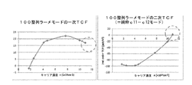
図3Jは、モード周波数が弾性パラメータ差分項c11-12にのみ依存するように[100]結晶方向と整列したラーメモード共振器に対して測定された実験データを示す。ドーピング濃度n<7.5*1019cmに対するデータ点は、文献(Jaakkola et al, "Determination of doping and temperature dependent elastic constants of degenerately doped silicon from MEMS resonators, " IEEE Transactions on Ultrasonics, Ferroelectrics, and Frequency Control . IEEE. Vol. 61 (2014) No: 7, 1063 - 1074)からのものであるが、最高ドーピング濃度に対する2つのデータ点はこれまで公表されていない。この実験データに基づいて、[100]整列ラーメモード共振器の二次TCFは高いドーパントレベルにおいてさらに大きな正値に達することが予測され得る。これは図3Iにおいて確かに推測され、b11-12項の挙動が推定される FIG. 3J shows experimental data measured for a lame mode resonator aligned with the [100] crystal direction such that the mode frequency depends only on the elastic parameter difference term c 11-12 . Data points for doping concentrations n <7.5 * 10 19 cm are given in the literature (Jaakkola et al, “Determination of doping and temperature dependent elastic constants of degenerately doped silicon from MEMS resonators,” IEEE Transactions on Ultrasonics, Ferroelectrics, and Frequency Control. Vol. 61 (2014) No: 7, 1063-1074), but two data points for the highest doping concentration have not been published so far. Based on this experimental data, it can be predicted that the second order TCF of the [100] aligned Larmed mode resonator will reach a larger positive value at high dopant levels. This is certainly inferred in FIG. 3I, and the behavior of the b11-12 term is estimated.
本発明は、共振器の多数の異なる共振周波数、ドーピング濃度、幾何学的構成(横方向形状及び厚さ等)の一部が図面に示され、明細書に記載されるのみであるが、その全部を包含するものと理解すべきであり、それらに共通していることは、共振器はビーム区分を備えていること、それらの特性は請求項に記載のドーピング濃度及び角度範囲内にあること、及びその結果ビーム区分が共振器の潜在的な他の部分と一緒に働いて共振器の共振周波数の総合温度依存性を最小化することにある。すべての可能なパラメータの組み合わせを詳細に包含することは不可能であるが、当業者は本明細書に開示する原理を利用して自身のニーズに適合する特定のパラメータの組み合わせを見つけることができることに留意すべきである。 The present invention shows only a part of the many different resonance frequencies, doping concentrations, geometric configurations (transverse shape and thickness etc.) of the resonator are shown in the drawings and described in the specification. It should be understood that they are all inclusive, and what is common to them is that the resonator has a beam section and that its characteristics are within the claimed doping concentration and angular range. And, as a result, the beam section works with potential other parts of the resonator to minimize the overall temperature dependence of the resonator's resonant frequency. While it is not possible to include all possible parameter combinations in detail, one skilled in the art can use the principles disclosed herein to find specific parameter combinations that meet his needs. Should be noted.
n型ドーパントに加えて、p型ドーパントが共振器に存在してもよい。例えば、結晶内に均一なp型バックグラウンドドーピングが存在してもよい。 In addition to n-type dopants, p-type dopants may be present in the resonator. For example, there may be uniform p-type background doping within the crystal.
本発明のマイクロ電気機械共振器のアクチュエータは、例えば圧電アクチュエータ又は静電アクチュエータとすることができ、またそれ自体周知の共振モードを励起するのに適した任意の他のアクチュエータとしてもよい。一実施形態によれば、アクチュエータは共振素子の上に配置された圧電アクチュエータとする。圧電アクチュエータは、例えば窒化アルミニウム(AlN)層及びモリブデン電極を備えてもよい。対称軸に沿って対称化された構造では、共振器装置の対称性を維持するために2つ以上のアクチュエータを対称軸に対して対称に配置してもよい。圧電アクチュエータも静電アクチュエータもそれ自体は周知であり、当業者によって本発明の共振器設計に適用し得るので、その詳細な記載は省略する。 The actuator of the microelectromechanical resonator of the present invention may be, for example, a piezoelectric actuator or an electrostatic actuator, and may be any other actuator suitable for exciting a resonance mode known per se. According to one embodiment, the actuator is a piezoelectric actuator disposed on the resonant element. The piezoelectric actuator may include, for example, an aluminum nitride (AlN) layer and a molybdenum electrode. In the structure symmetrized along the symmetry axis, two or more actuators may be arranged symmetrically with respect to the symmetry axis in order to maintain the symmetry of the resonator device. Since piezoelectric actuators and electrostatic actuators are well known per se and can be applied to the resonator design of the present invention by those skilled in the art, a detailed description thereof will be omitted.
Claims (21)
前記支持構造に懸架された共振器であって、少なくとも一つのビームを有し、
前記ビームは、
長手方向軸を有し、
n型ドーパント剤があるドーピング濃度にドープされ、
長さ伸縮、屈曲又はねじれ共振モードで共振し得るものである、
共振器と、
前記共振器に前記長さ伸縮、屈曲又はねじれ共振モードを励起するアクチュエータと、を備えるマイクロ電気機械共振器装置において、
前記支持構造及び前記共振器は(100)又は(110)配向シリコン半導体ウェハから製造され、
前記共振モードがねじれモードである場合には、前記ドーピング濃度は1.1*1020cm−3以上であり、
前記共振モードが長さ伸縮又は屈曲モードである場合には、前記ドーピング濃度は少なくとも1.2*10 20 cm −3 であり、
前記共振モードがねじれモードである場合には、前記少なくとも1つのビームの面外アスペクト比が2未満であり、
前記ビームの長手方向軸は、
前記共振モードが長さ伸縮又は屈曲モードである場合には、前記ウェハの[100]結晶方向に対して17±10度の角度に向けられ、
前記共振モードがねじれモードである場合には、前記ウェハの「110」結晶方向に対して0±35度の角度に向けられている、ことを特徴とする共振器装置。 A support structure;
A resonator suspended on said support structure, comprising at least one beam;
The beam is
Has a longitudinal axis;
an n-type dopant agent is doped to a certain doping concentration;
It can resonate in length expansion / contraction, bending or torsional resonance modes,
A resonator,
An actuator that excites the length expansion, contraction, or torsional resonance modes in the resonator, and a microelectromechanical resonator device comprising:
The support structure and the resonator are manufactured from a (100) or (110) oriented silicon semiconductor wafer;
When the resonance mode is a twist mode, the doping concentration is 1.1 * 10 20 cm −3 or more,
When the resonance mode is a length expansion / contraction or bending mode, the doping concentration is at least 1.2 * 10 20 cm −3 ,
If the resonant mode is a torsion mode, the out-of-plane aspect ratio of the at least one beam is less than 2,
The longitudinal axis of the beam is
When the resonance mode is a length expansion / contraction or bending mode, it is directed at an angle of 17 ± 10 degrees with respect to the [100] crystal direction of the wafer;
Wherein when the resonance mode is torsional mode, 0 that are oriented at an angle of 35 degrees ± for the "110" crystallographic direction of the wafer, the resonator device comprising a call.
前記共振器全体は、前記共振モードが長さ伸縮又は屈曲モードの場合には前記[100]方向と、又は前記共振モードがねじれモードの場合には前記[110]方向と本質的に平行の対称軸を有する、
ことを特徴とする請求項1又は4記載の共振器装置。 The resonator comprises at least two beams having a longitudinal axis oriented at the angle;
The entire resonator is symmetric essentially in parallel with the [100] direction when the resonance mode is length expansion / contraction or bending mode, or with the [110] direction when the resonance mode is torsional mode. Having an axis,
5. The resonator device according to claim 1, wherein the resonator device is a resonator device.
それらの第1の端で、前記共振モードが長さ伸縮又は屈曲モードの場合には前記[100]方向と、又は前記共振モードがねじれモードの場合には前記[110]方向と本質的に平行の対称軸を有する共通のベース部分に接続され、且つ
前記ウェハの面内で、前記共通ベース部分から前記[100]又は前記[110]方向に対して等しい角度で前記方向の両側に延在している、
ことを特徴とする請求項4又は5記載の共振器装置。 The at least two beams are
At their first end, they are essentially parallel to the [100] direction when the resonant mode is length-stretching or bending mode, or to the [110] direction when the resonant mode is torsional mode. Connected to a common base portion having an axis of symmetry and extending from the common base portion to both sides of the direction at an equal angle with respect to the [100] or [110] direction within the plane of the wafer. ing,
The resonator device according to claim 4 or 5, wherein
ことを特徴とする請求項1−10のいずれかに記載の共振器装置。 The resonance mode is a bending mode, and the bending surface is in the wafer surface and / or outside the wafer surface,
The resonator device according to claim 1, wherein the resonator device is a resonator device.
前記ビームは(100)ウェハ面に製造され、前記ビームの長手方向軸は前記[110]結晶方向に対して0±20度に向けられている、
ことを特徴とする請求項14又は15記載の共振器装置。 The beam is manufactured on a (110) wafer surface and the longitudinal axis of the beam is oriented at 0 ± 35 degrees with respect to the [110] crystal direction, or the beam is manufactured on a (100) wafer surface. The longitudinal axis of the beam is oriented at 0 ± 20 degrees with respect to the [110] crystal direction,
16. The resonator device according to claim 14, wherein the resonator device is a resonator device.
前記ビームは(110)ウェハ面に製造され、その面外アスペクト比は0.9又はそれより小さい、
ことを特徴とする請求項14−16のいずれかに記載の共振器装置。 The beam is manufactured on a (100) wafer surface and has an out-of-plane aspect ratio of 1.25 or less, or the beam is manufactured on a (110) wafer surface and has an out-of-plane aspect ratio of 0.9 or less. Smaller,
A resonator device according to any of claims 14-16.
Applications Claiming Priority (3)
| Application Number | Priority Date | Filing Date | Title |
|---|---|---|---|
| FI20145868 | 2014-10-03 | ||
| FI20145868 | 2014-10-03 | ||
| PCT/FI2015/050657 WO2016051022A1 (en) | 2014-10-03 | 2015-10-02 | Temperature compensated beam resonator |
Publications (2)
| Publication Number | Publication Date |
|---|---|
| JP2017536012A JP2017536012A (en) | 2017-11-30 |
| JP6587681B2 true JP6587681B2 (en) | 2019-10-09 |
Family
ID=54325006
Family Applications (1)
| Application Number | Title | Priority Date | Filing Date |
|---|---|---|---|
| JP2017517781A Active JP6587681B2 (en) | 2014-10-03 | 2015-10-02 | Temperature compensated beam resonator |
Country Status (5)
| Country | Link |
|---|---|
| US (1) | US10056877B2 (en) |
| EP (1) | EP3202036B1 (en) |
| JP (1) | JP6587681B2 (en) |
| CN (1) | CN107005223B (en) |
| WO (1) | WO2016051022A1 (en) |
Families Citing this family (12)
| Publication number | Priority date | Publication date | Assignee | Title |
|---|---|---|---|---|
| US9695036B1 (en) | 2012-02-02 | 2017-07-04 | Sitime Corporation | Temperature insensitive resonant elements and oscillators and methods of designing and manufacturing same |
| US9705470B1 (en) | 2014-02-09 | 2017-07-11 | Sitime Corporation | Temperature-engineered MEMS resonator |
| US9712128B2 (en) | 2014-02-09 | 2017-07-18 | Sitime Corporation | Microelectromechanical resonator |
| CN107408933B (en) * | 2014-10-03 | 2020-11-20 | 芬兰国家技术研究中心股份公司 | Temperature compensation composite resonator |
| JP6587681B2 (en) * | 2014-10-03 | 2019-10-09 | テクノロギアン トゥトキムスケスクス ヴェーテーテー オイ | Temperature compensated beam resonator |
| US10676349B1 (en) | 2016-08-12 | 2020-06-09 | Sitime Corporation | MEMS resonator |
| FI128032B (en) * | 2017-09-05 | 2019-08-15 | Tikitin Oy | Oven-controlled frequency reference oscillator and method of fabricating thereof |
| US11533042B2 (en) | 2018-01-16 | 2022-12-20 | Georgia Tech Research Corporation | Distributed-mode beam and frame resonators for high frequency timing circuits |
| FI130145B (en) * | 2019-04-15 | 2023-03-13 | Tikitin Oy | Microelectromechanical resonator |
| FI20205386A1 (en) * | 2020-04-15 | 2021-10-16 | Kyocera Tikitin Oy | Microelectromechanical system resonator assembly |
| CN114199418A (en) * | 2021-11-29 | 2022-03-18 | 北京晨晶电子有限公司 | Quartz tuning fork pressure sensor |
| CN116429281B (en) * | 2023-06-13 | 2023-09-08 | 麦斯塔微电子(深圳)有限公司 | Resonator based on array structure and temperature measurement method |
Family Cites Families (30)
| Publication number | Priority date | Publication date | Assignee | Title |
|---|---|---|---|---|
| JPS5336191A (en) * | 1976-09-16 | 1978-04-04 | Seikosha Kk | Tuning fork piezooelectric vibrator |
| JPS6064516A (en) * | 1983-09-20 | 1985-04-13 | Seiko Instr & Electronics Ltd | Combined crystal resonator |
| US7312674B2 (en) * | 2002-08-06 | 2007-12-25 | The Charles Stark Draper Laboratory, Inc. | Resonator system with a plurality of individual mechanically coupled resonators and method of making same |
| US6987432B2 (en) * | 2003-04-16 | 2006-01-17 | Robert Bosch Gmbh | Temperature compensation for silicon MEMS resonator |
| FR2854993B1 (en) * | 2003-05-15 | 2005-07-15 | Suisse Electronique Microtech | INTEGRATED RESONATORS AND BASE OF TIME INCORPORATING SUCH RESONATORS |
| WO2006013741A1 (en) * | 2004-08-05 | 2006-02-09 | Matsushita Electric Industrial Co., Ltd. | Tortional resonator and filter using this |
| US7205867B2 (en) * | 2005-05-19 | 2007-04-17 | Robert Bosch Gmbh | Microelectromechanical resonator structure, and method of designing, operating and using same |
| CH700716B1 (en) * | 2006-10-09 | 2010-10-15 | Suisse Electronique Microtech | Tuning fork resonator type silicon. |
| US7591201B1 (en) * | 2007-03-09 | 2009-09-22 | Silicon Clocks, Inc. | MEMS structure having a compensated resonating member |
| WO2010044058A1 (en) * | 2008-10-14 | 2010-04-22 | Nxp B.V. | Frame-shaped mems piezoresistive resonator |
| US8354332B2 (en) * | 2008-11-26 | 2013-01-15 | Georgia Tech Research Corporation | Methods of forming micro-electromichanical resonators having boron-doped resonator bodies containing eutectic alloys |
| JP5786303B2 (en) * | 2009-12-10 | 2015-09-30 | セイコーエプソン株式会社 | Vibrating piece, vibrator, physical quantity sensor, and electronic device |
| US20110210801A1 (en) * | 2010-02-26 | 2011-09-01 | Imec | Temperature measurement system comprising a resonant mems device |
| EP2395660B1 (en) * | 2010-06-10 | 2013-08-14 | Nxp B.V. | MEMS resonators |
| FI20105851A (en) * | 2010-08-13 | 2012-02-14 | Valtion Teknillinen | Micromechanical resonator and process for its manufacture |
| FI126586B (en) * | 2011-02-17 | 2017-02-28 | Teknologian Tutkimuskeskus Vtt Oy | New micromechanical devices |
| FI123933B (en) * | 2011-05-13 | 2013-12-31 | Teknologian Tutkimuskeskus Vtt | A micromechanical device and method for its design |
| US9742373B2 (en) * | 2011-10-31 | 2017-08-22 | The Regents Of The University Of Michigan | Method of manufacturing a temperature-compensated micromechanical resonator |
| EP2590325A1 (en) * | 2011-11-04 | 2013-05-08 | The Swatch Group Research and Development Ltd. | Thermally compensated ceramic resonator |
| US9695036B1 (en) * | 2012-02-02 | 2017-07-04 | Sitime Corporation | Temperature insensitive resonant elements and oscillators and methods of designing and manufacturing same |
| SG11201501005YA (en) * | 2012-09-13 | 2015-05-28 | Murata Manufacturing Co | Vibrating device and manufacturing method therefor |
| FR3002095B1 (en) * | 2013-02-14 | 2015-02-20 | Onera (Off Nat Aerospatiale) | FLAT STRUCTURE OF MECHANICAL RESONATOR DECOUPLED BY FLEXION AND EXTENSION-COMPRESSION VIBRATIONS |
| WO2014129979A1 (en) * | 2013-02-22 | 2014-08-28 | Agency For Science, Technology And Research | Surface acoustic wave device |
| JP6107333B2 (en) * | 2013-03-29 | 2017-04-05 | セイコーエプソン株式会社 | Vibrator, oscillator, electronic device, and moving object |
| SG11201508862UA (en) * | 2013-05-13 | 2015-11-27 | Murata Manufacturing Co | Vibrating device |
| US9412934B2 (en) * | 2013-05-20 | 2016-08-09 | Murata Manufacturing Co., Ltd. | Microelectromechanical resonator |
| US9712128B2 (en) * | 2014-02-09 | 2017-07-18 | Sitime Corporation | Microelectromechanical resonator |
| JP6587681B2 (en) * | 2014-10-03 | 2019-10-09 | テクノロギアン トゥトキムスケスクス ヴェーテーテー オイ | Temperature compensated beam resonator |
| JP6567661B2 (en) * | 2014-10-03 | 2019-08-28 | テクノロギアン トゥトキムスケスクス ヴェーテーテー オイ | Temperature compensated plate resonator |
| CN107408933B (en) * | 2014-10-03 | 2020-11-20 | 芬兰国家技术研究中心股份公司 | Temperature compensation composite resonator |
-
2015
- 2015-10-02 JP JP2017517781A patent/JP6587681B2/en active Active
- 2015-10-02 EP EP15780911.2A patent/EP3202036B1/en active Active
- 2015-10-02 WO PCT/FI2015/050657 patent/WO2016051022A1/en active Application Filing
- 2015-10-02 CN CN201580064515.0A patent/CN107005223B/en active Active
- 2015-10-05 US US14/874,522 patent/US10056877B2/en active Active
Also Published As
| Publication number | Publication date |
|---|---|
| JP2017536012A (en) | 2017-11-30 |
| EP3202036A1 (en) | 2017-08-09 |
| US10056877B2 (en) | 2018-08-21 |
| EP3202036B1 (en) | 2020-05-27 |
| WO2016051022A1 (en) | 2016-04-07 |
| US20160099703A1 (en) | 2016-04-07 |
| CN107005223A (en) | 2017-08-01 |
| CN107005223B (en) | 2021-06-04 |
Similar Documents
| Publication | Publication Date | Title |
|---|---|---|
| JP6587681B2 (en) | Temperature compensated beam resonator | |
| JP6567661B2 (en) | Temperature compensated plate resonator | |
| JP6615191B2 (en) | Temperature compensated composite resonator | |
| JP6109752B2 (en) | New micro mechanical device | |
| JP7266077B2 (en) | micromechanical resonator | |
| US7939990B2 (en) | Thin-film bulk acoustic resonators having perforated bodies that provide reduced susceptibility to process-induced lateral dimension variations | |
| US7956517B1 (en) | MEMS structure having a stress inverter temperature-compensated resonator member | |
| JP2021513243A (en) | Coupled MEMS resonator | |
| US10965267B2 (en) | Micromechanical resonator and method for trimming micromechanical resonator | |
| CN110024285B (en) | MEMS resonator with suppressed parasitic modes | |
| JP2024021067A (en) | Vibrator, MEMS oscillator, and vibrator manufacturing method |
Legal Events
| Date | Code | Title | Description |
|---|---|---|---|
| A621 | Written request for application examination |
Free format text: JAPANESE INTERMEDIATE CODE: A621 Effective date: 20170518 |
|
| A977 | Report on retrieval |
Free format text: JAPANESE INTERMEDIATE CODE: A971007 Effective date: 20180718 |
|
| A131 | Notification of reasons for refusal |
Free format text: JAPANESE INTERMEDIATE CODE: A131 Effective date: 20180724 |
|
| A521 | Request for written amendment filed |
Free format text: JAPANESE INTERMEDIATE CODE: A523 Effective date: 20181023 |
|
| A131 | Notification of reasons for refusal |
Free format text: JAPANESE INTERMEDIATE CODE: A131 Effective date: 20190305 |
|
| A521 | Request for written amendment filed |
Free format text: JAPANESE INTERMEDIATE CODE: A523 Effective date: 20190605 |
|
| TRDD | Decision of grant or rejection written | ||
| A01 | Written decision to grant a patent or to grant a registration (utility model) |
Free format text: JAPANESE INTERMEDIATE CODE: A01 Effective date: 20190820 |
|
| A61 | First payment of annual fees (during grant procedure) |
Free format text: JAPANESE INTERMEDIATE CODE: A61 Effective date: 20190910 |
|
| R150 | Certificate of patent or registration of utility model |
Ref document number: 6587681 Country of ref document: JP Free format text: JAPANESE INTERMEDIATE CODE: R150 |
|
| R250 | Receipt of annual fees |
Free format text: JAPANESE INTERMEDIATE CODE: R250 |
|
| R250 | Receipt of annual fees |
Free format text: JAPANESE INTERMEDIATE CODE: R250 |