JP6587350B2 - GAS TURBINE COOLING SYSTEM, GAS TURBINE EQUIPMENT HAVING THE SAME, AND METHOD FOR CONTROLLING GAS TURBINE COOLING SYSTEM - Google Patents
GAS TURBINE COOLING SYSTEM, GAS TURBINE EQUIPMENT HAVING THE SAME, AND METHOD FOR CONTROLLING GAS TURBINE COOLING SYSTEM Download PDFInfo
- Publication number
- JP6587350B2 JP6587350B2 JP2016010765A JP2016010765A JP6587350B2 JP 6587350 B2 JP6587350 B2 JP 6587350B2 JP 2016010765 A JP2016010765 A JP 2016010765A JP 2016010765 A JP2016010765 A JP 2016010765A JP 6587350 B2 JP6587350 B2 JP 6587350B2
- Authority
- JP
- Japan
- Prior art keywords
- command
- valve
- valve command
- gas turbine
- opening
- Prior art date
- Legal status (The legal status is an assumption and is not a legal conclusion. Google has not performed a legal analysis and makes no representation as to the accuracy of the status listed.)
- Active
Links
Images


Classifications
-
- F—MECHANICAL ENGINEERING; LIGHTING; HEATING; WEAPONS; BLASTING
- F02—COMBUSTION ENGINES; HOT-GAS OR COMBUSTION-PRODUCT ENGINE PLANTS
- F02C—GAS-TURBINE PLANTS; AIR INTAKES FOR JET-PROPULSION PLANTS; CONTROLLING FUEL SUPPLY IN AIR-BREATHING JET-PROPULSION PLANTS
- F02C7/00—Features, components parts, details or accessories, not provided for in, or of interest apart form groups F02C1/00 - F02C6/00; Air intakes for jet-propulsion plants
- F02C7/12—Cooling of plants
- F02C7/16—Cooling of plants characterised by cooling medium
- F02C7/18—Cooling of plants characterised by cooling medium the medium being gaseous, e.g. air
-
- F—MECHANICAL ENGINEERING; LIGHTING; HEATING; WEAPONS; BLASTING
- F01—MACHINES OR ENGINES IN GENERAL; ENGINE PLANTS IN GENERAL; STEAM ENGINES
- F01D—NON-POSITIVE DISPLACEMENT MACHINES OR ENGINES, e.g. STEAM TURBINES
- F01D17/00—Regulating or controlling by varying flow
- F01D17/10—Final actuators
- F01D17/12—Final actuators arranged in stator parts
- F01D17/14—Final actuators arranged in stator parts varying effective cross-sectional area of nozzles or guide conduits
- F01D17/141—Final actuators arranged in stator parts varying effective cross-sectional area of nozzles or guide conduits by means of shiftable members or valves obturating part of the flow path
- F01D17/145—Final actuators arranged in stator parts varying effective cross-sectional area of nozzles or guide conduits by means of shiftable members or valves obturating part of the flow path by means of valves, e.g. for steam turbines
-
- F—MECHANICAL ENGINEERING; LIGHTING; HEATING; WEAPONS; BLASTING
- F01—MACHINES OR ENGINES IN GENERAL; ENGINE PLANTS IN GENERAL; STEAM ENGINES
- F01D—NON-POSITIVE DISPLACEMENT MACHINES OR ENGINES, e.g. STEAM TURBINES
- F01D25/00—Component parts, details, or accessories, not provided for in, or of interest apart from, other groups
- F01D25/08—Cooling; Heating; Heat-insulation
- F01D25/12—Cooling
-
- F—MECHANICAL ENGINEERING; LIGHTING; HEATING; WEAPONS; BLASTING
- F02—COMBUSTION ENGINES; HOT-GAS OR COMBUSTION-PRODUCT ENGINE PLANTS
- F02C—GAS-TURBINE PLANTS; AIR INTAKES FOR JET-PROPULSION PLANTS; CONTROLLING FUEL SUPPLY IN AIR-BREATHING JET-PROPULSION PLANTS
- F02C6/00—Plural gas-turbine plants; Combinations of gas-turbine plants with other apparatus; Adaptations of gas- turbine plants for special use
- F02C6/04—Gas-turbine plants providing heated or pressurised working fluid for other apparatus, e.g. without mechanical power output
- F02C6/06—Gas-turbine plants providing heated or pressurised working fluid for other apparatus, e.g. without mechanical power output providing compressed gas
- F02C6/08—Gas-turbine plants providing heated or pressurised working fluid for other apparatus, e.g. without mechanical power output providing compressed gas the gas being bled from the gas-turbine compressor
-
- F—MECHANICAL ENGINEERING; LIGHTING; HEATING; WEAPONS; BLASTING
- F02—COMBUSTION ENGINES; HOT-GAS OR COMBUSTION-PRODUCT ENGINE PLANTS
- F02C—GAS-TURBINE PLANTS; AIR INTAKES FOR JET-PROPULSION PLANTS; CONTROLLING FUEL SUPPLY IN AIR-BREATHING JET-PROPULSION PLANTS
- F02C9/00—Controlling gas-turbine plants; Controlling fuel supply in air- breathing jet-propulsion plants
- F02C9/16—Control of working fluid flow
- F02C9/18—Control of working fluid flow by bleeding, bypassing or acting on variable working fluid interconnections between turbines or compressors or their stages
-
- F—MECHANICAL ENGINEERING; LIGHTING; HEATING; WEAPONS; BLASTING
- F05—INDEXING SCHEMES RELATING TO ENGINES OR PUMPS IN VARIOUS SUBCLASSES OF CLASSES F01-F04
- F05D—INDEXING SCHEME FOR ASPECTS RELATING TO NON-POSITIVE-DISPLACEMENT MACHINES OR ENGINES, GAS-TURBINES OR JET-PROPULSION PLANTS
- F05D2260/00—Function
- F05D2260/20—Heat transfer, e.g. cooling
Landscapes
- Engineering & Computer Science (AREA)
- Chemical & Material Sciences (AREA)
- Combustion & Propulsion (AREA)
- Mechanical Engineering (AREA)
- General Engineering & Computer Science (AREA)
- Physics & Mathematics (AREA)
- Fluid Mechanics (AREA)
- Control Of Turbines (AREA)
Description
本発明は、ガスタービン中で燃焼ガスに接する高温部品を冷却するためのガスタービン冷却系統、これを備えるガスタービン設備、ガスタービン冷却系統の制御方法に関する。 The present invention relates to a gas turbine cooling system for cooling a high-temperature component in contact with combustion gas in a gas turbine, a gas turbine facility including the same, and a control method for the gas turbine cooling system.
ガスタービンは、外気を圧縮して圧縮空気を生成する空気圧縮機と、燃料を圧縮空気中で燃焼させて燃焼ガスを生成する燃焼器と、燃焼ガスにより駆動するタービンと、を備えている。ガスタービンでは、燃焼器の燃焼筒や、タービンの動翼や静翼等が高温の燃焼ガスに晒されるため、これらの高温部品を冷却して、これらの高温部品を燃焼ガスの熱から保護する必要がある。 The gas turbine includes an air compressor that compresses outside air to generate compressed air, a combustor that generates combustion gas by burning fuel in the compressed air, and a turbine that is driven by the combustion gas. In a gas turbine, the combustion cylinder of the combustor, the moving blades and stationary blades of the turbine, etc. are exposed to high-temperature combustion gas. Therefore, these high-temperature parts are cooled to protect these high-temperature parts from the heat of the combustion gas. There is a need.
以下の特許文献1には、ガスタービンの高温部品の一つである燃焼器の燃焼筒を冷却するための冷却系統が開示されている。この冷却系統は、ガスタービンの空気圧縮機で圧縮された圧縮空気を燃焼筒に導く冷却空気ラインと、冷却空気ライン中の圧縮空気を冷却して冷却空気にする冷却器と、冷却空気ライン中の冷却空気を昇圧する昇圧機と、を備えている。
ガスタービンの負荷遮断時には、ガスタービンの運転状態が急激に変化する。しかしながら、上記特許文献1に記載の技術では、負荷遮断時の対応について考慮されていない。
When the load of the gas turbine is interrupted, the operating state of the gas turbine changes abruptly. However, the technique described in
そこで、本発明は、負荷遮断時でも高温部品を冷却することができるガスタービン冷却系統、これを備えるガスタービン設備、ガスタービン冷却系統の制御方法を提供することを目的とする。 Then, an object of this invention is to provide the control method of the gas turbine cooling system which can cool a high temperature component even at the time of load interruption, the gas turbine equipment provided with this, and a gas turbine cooling system.
上記目的を達成するための発明に係る一態様としてのガスタービン冷却系統は、
ガスタービンの空気圧縮機で圧縮された圧縮空気をガスタービン中で燃焼ガスに接する高温部品に導く冷却空気ラインと、前記冷却空気ライン中の前記圧縮空気を冷却して冷却空気にする冷却器と、前記冷却空気ライン中の前記冷却空気を昇圧する昇圧機と、前記冷却空気ライン中で前記昇圧機よりも前記高温部品側のラインである吐出ライン中の前記冷却空気を前記冷却空気ライン中で前記昇圧機よりも前記空気圧縮機側の吸気ラインに戻すリターンラインと、前記リターンラインに設けられ、前記リターンラインを流れる前記冷却空気の流量を調節するリターン弁と、前記吸気ラインを流れる前記冷却空気の状態量と前記吐出ラインを流れる前記冷却空気の状態量とを検知する検知器と、前記リターン弁の開度を制御する制御装置と、を備え、
前記制御装置は、前記ガスタービンの負荷遮断を示す負荷遮断指令を受け付ける受付部と、前記検知器で検知された前記状態量に応じた前記リターン弁の開度を示す第一弁指令を発生する第一弁指令発生部と、前記受付部が前記負荷遮断指令を受け付けると、前記検知器で検知された前記状態量に関わらず、前記リターン弁の開度を予め定めれた遮断時開度へ強制的に大きくする旨の弁指令を第二弁指令として発生する第二弁指令発生部と、前記第二弁指令発生部が前記第二弁指令を発生している場合、前記第二弁指令に基づくリターン弁指令を前記リターン弁に出力し、前記第二弁指令発生部が前記第二弁指令を発生していない場合、前記ガスタービンの状態に応じて前記第一弁指令に基づくリターン弁指令を前記リターン弁に出力するリターン弁指令出力部と、を有する。
A gas turbine cooling system as one aspect according to the invention for achieving the above object is as follows:
A cooling air line that guides the compressed air compressed by the air compressor of the gas turbine to a high-temperature component that contacts the combustion gas in the gas turbine; and a cooler that cools the compressed air in the cooling air line into cooling air. A booster that pressurizes the cooling air in the cooling air line, and the cooling air in the discharge line that is a line on the high-temperature components side of the booster in the cooling air line in the cooling air line A return line that returns to the intake line closer to the air compressor than the booster, a return valve that is provided in the return line and adjusts the flow rate of the cooling air that flows through the return line, and the cooling that flows through the intake line A detector that detects a state quantity of air and a state quantity of the cooling air flowing through the discharge line, and a control device that controls the opening of the return valve. For example,
The control device generates a first valve command indicating a degree of opening of the return valve according to the state quantity detected by the detector and a receiving unit that receives a load cutoff command indicating load cutoff of the gas turbine When the first valve command generating unit and the receiving unit receive the load shut-off command, the opening degree of the return valve is set to a predetermined shut-off opening degree regardless of the state quantity detected by the detector. A second valve command generating unit that generates a valve command for forcibly increasing as a second valve command, and the second valve command generating unit generates the second valve command when the second valve command generating unit generates the second valve command. When the second valve command generator does not generate the second valve command, the return valve based on the first valve command is output according to the state of the gas turbine. Command to output the command to the return valve. It has a chromatography down valve command output unit.
負荷遮断時には、空気圧縮機の吐出圧が急激に低下する。このため、冷却系統における昇圧機の吸気圧も、空気圧縮機の吐出圧の急激な低下に伴って、急激に低下する。一方、昇圧機の吐出圧は、冷却空気ライン等の存在により、空気圧縮機の吐出圧の低下に対して遅れて低下する。このため、負荷遮断直後では、一時的に、昇圧機の圧力比が高まる。よって、負荷遮断時には、昇圧機でのサージング発生の可能性が急激に高まる。 When the load is shut off, the discharge pressure of the air compressor is rapidly reduced. For this reason, the intake pressure of the booster in the cooling system also rapidly decreases as the discharge pressure of the air compressor decreases rapidly. On the other hand, the discharge pressure of the booster decreases with a delay from the decrease in the discharge pressure of the air compressor due to the presence of a cooling air line or the like. For this reason, immediately after the load is cut off, the pressure ratio of the booster temporarily increases. Therefore, when the load is interrupted, the possibility of occurrence of surging in the booster increases rapidly.
そこで、当該冷却系統では、受付部が負荷遮断指令を受け付けると、第二弁指令発生部が第二弁指令を発生する。この第二弁指令は、検知器で検知された状態量に関わらず、リターン弁の開度を予め定めれた遮断時開度へ強制的に大きくする旨の弁指令である。第二弁指令発生部が第二弁指令を発生すると、リターン弁指令出力部は、この第二弁指令に基づくリターン弁指令をリターン弁に出力する。この結果、負荷遮断直後に、リターン弁の開度は、遮断時開度へ強制的に大きくなる。 Therefore, in the cooling system, when the receiving unit receives the load shedding command, the second valve command generating unit generates the second valve command. This second valve command is a valve command for forcibly increasing the opening degree of the return valve to a predetermined opening degree at the time of shutoff regardless of the state quantity detected by the detector. When the second valve command generator generates the second valve command, the return valve command output unit outputs a return valve command based on the second valve command to the return valve. As a result, immediately after the load is cut off, the opening degree of the return valve is forcibly increased to the opening degree at the time of breaking.
リターン弁の開度が大きくなると、リターンラインを流れる冷却空気の流量が多くなるため、昇圧機を流れる冷却空気の体積流量は増加する。このため、リターン弁の開度が大きくなると、昇圧機の体積吸込流量が増加する。また、リターン弁の開度が大きくなると、昇圧機の吐出圧と吸気圧との差が小さくなり、昇圧機の圧力比が小さくなる。よって、リターン弁の開度が大きくなると、サージング発生の可能性が低下する。 When the opening degree of the return valve increases, the flow rate of the cooling air flowing through the return line increases, so the volume flow rate of the cooling air flowing through the booster increases. For this reason, when the opening degree of the return valve increases, the volume suction flow rate of the booster increases. Moreover, when the opening degree of the return valve is increased, the difference between the discharge pressure of the booster and the intake pressure is decreased, and the pressure ratio of the booster is decreased. Therefore, when the opening degree of the return valve increases, the possibility of occurrence of surging decreases.
従って、当該冷却系統では、負荷遮断時における昇圧機でのサージング発生の可能性を抑えることができる。このため、当該冷却系統によれば、負荷遮断時でも高温部品に冷却空気を送り、この高温部品を冷却することができる。 Therefore, in the cooling system, the possibility of surging occurring in the booster at the time of load interruption can be suppressed. For this reason, according to the said cooling system, cooling air can be sent to a high temperature component even at the time of load interruption, and this high temperature component can be cooled.
ここで、前記ガスタービン冷却系統において、前記遮断時開度は、前記リターン弁の全開の開度であってもよい。 Here, in the gas turbine cooling system, the shut-off opening may be a fully opened opening of the return valve.
当該冷却系統では、遮断時開度がリターン弁の全開の開度であるため、負荷遮断直後にリターン弁の開度は全開になる。このため、リターンラインを流れる冷却空気の流量が多くなり、負荷遮断時における昇圧機でのサージング発生の可能性をより抑えることができる。 In the cooling system, since the opening degree at the time of interruption is the opening degree of the fully opened return valve, the opening degree of the return valve is fully opened immediately after the load is interrupted. For this reason, the flow volume of the cooling air which flows through a return line increases, and the possibility of the surging generation | occurrence | production by a booster at the time of load interruption can be suppressed more.
また、以上のいずれかの前記ガスタービン冷却系統において、前記第二弁指令発生部は、前記受付部が前記負荷遮断指令を受け付けると、前記昇圧機のサージング発生の可能性が低くなったとされる予め定められている条件が満た条件が満たされるまで、前記遮断時開度を維持する旨の弁指令を前記第二弁指令として発生してもよい。 In any one of the gas turbine cooling systems described above, the second valve command generation unit is less likely to generate surging of the booster when the reception unit receives the load shedding command. A valve command for maintaining the shut-off opening degree may be generated as the second valve command until a predetermined condition is satisfied.
当該冷却系統では、昇圧機でのサージング発生の可能性が低くなったとされる条件が満たされるまで、リターン弁の開度が遮断時開度に維持される。 In the cooling system, the opening degree of the return valve is maintained at the shut-off opening degree until the condition that the possibility of occurrence of surging in the booster is reduced is satisfied.
また、前記条件が満たされるまで、遮断時開度を維持する旨の弁指令を前記第二弁指令として発生する、前記ガスタービン冷却系統において、前記第二弁指令発生部は、前記予め定められた条件が満たされると、前記リターン弁の開度を前記遮断時開度から小さくする旨の弁指令を前記第二弁指令として発生してもよい。 In the gas turbine cooling system, a valve command for maintaining the shut-off opening degree is generated as the second valve command until the condition is satisfied. When the above condition is satisfied, a valve command for reducing the opening of the return valve from the opening at the time of shutoff may be generated as the second valve command.
リターン弁の開度を遮断時開度にしても、昇圧機から吐出ラインを経て高温部品に冷却空気が供給される。しかしながら、リターン弁の開度を遮断時開度にすると、昇圧機から吐出された冷却空気の一部がリターン弁を通ることになり、高温部品に供給される冷却空気の流量は減少する。このため、高温部品は焼損する可能性が生じる。 Even if the opening degree of the return valve is set to the opening degree at the shut-off time, the cooling air is supplied from the booster to the high-temperature parts through the discharge line. However, when the opening degree of the return valve is set to the opening degree at the time of shut-off, a part of the cooling air discharged from the booster passes through the return valve, and the flow rate of the cooling air supplied to the high-temperature parts decreases. For this reason, a high temperature component may burn out.
しかしながら、当該冷却系統では、負荷遮断指令を受け付けてから昇圧機でのサージング発生の可能性が低くなったとされる条件を満たすと、リターン弁の開度が小さくなる。この結果、昇圧機から吐出ラインを経て高温部品に供給される冷却空気の流量が増加し、高温部品の焼損を抑えることができる。 However, in the cooling system, when the condition that the possibility of occurrence of surging in the booster is reduced after receiving the load shedding command, the opening degree of the return valve is reduced. As a result, the flow rate of the cooling air supplied from the booster to the high temperature parts via the discharge line increases, and the high temperature parts can be prevented from being burned out.
また、前記条件が満たされると、リターン弁の開度を前記遮断時開度から小さくする旨の弁指令を前記第二弁指令として発生する、前記ガスタービン冷却系統において、前記第一弁指令発生部は、前記検知器で検知された前記状態量がサージング発生の可能性が高まっていることを示す場合、前記リターン弁の開度が大きくなる開度を示す前記第一弁指令を発生し、前記検知器で検知された前記状態量がサージング発生の可能性が低下していることを示す場合、前記リターン弁の開度が小さくなる開度を示す前記第一弁指令を発生し、前記予め定められた条件が満たされたときの前記第二弁指令が示す開度の閉側への変化率は、サージング発生の可能性が低下しているときの前記第一弁指令が示す開度の閉側への最大変化率より大きくてもよい。 In the gas turbine cooling system, when the condition is satisfied, a valve command for reducing the opening degree of the return valve from the shut-off opening degree is generated as the second valve command. When the state quantity detected by the detector indicates that the possibility of occurrence of surging is increased, the unit generates the first valve command indicating an opening degree at which the opening degree of the return valve is increased, When the state quantity detected by the detector indicates that the possibility of occurrence of surging is reduced, the first valve command indicating an opening degree at which the opening degree of the return valve is reduced is generated, The rate of change to the closing side of the opening indicated by the second valve command when a predetermined condition is satisfied is the rate of change of the opening indicated by the first valve command when the possibility of surging is reduced. It may be greater than the maximum rate of change to the closing side .
当該冷却系統では、負荷遮断指令を受け付けてから昇圧機でのサージング発生の可能性が低くなったとされる条件を満たすと、リターン弁の開度が急激に小さくなる。この結果、昇圧機から吐出ラインを経て高温部品に供給される冷却空気の流量が急激に増加し、高温部品の焼損をより抑えることができる。 In the cooling system, when the condition that the possibility of occurrence of surging in the booster is reduced after receiving the load shedding command, the opening degree of the return valve decreases rapidly. As a result, the flow rate of the cooling air supplied from the booster to the high temperature parts via the discharge line increases rapidly , and the high temperature parts can be prevented from being burned out.
また、前記条件が満たされると、リターン弁の開度を前記遮断時開度から小さくする旨の弁指令を前記第二弁指令として発生する前記ガスタービン冷却系統において、前記予め定められた条件が満たされたときの前記第二弁指令が示す開度の変化率は、予め定められた変化率であってもよい。 Further, in the gas turbine cooling system that generates, as the second valve command, a valve command for reducing the opening degree of the return valve from the shut-off opening degree when the condition is satisfied, the predetermined condition is The rate of change of the opening indicated by the second valve command when satisfied may be a predetermined rate of change.
また、前記条件が満たされると、リターン弁の開度を前記遮断時開度から小さくする旨の弁指令を前記第二弁指令として発生する、前記ガスタービン冷却系統において、前記第二弁指令発生部は、前記予め定められた条件が満たされたとき、前記検知器で検知された前記状態量に応じて定めた開度を示す弁指令を前記第二弁指令として発生してもよい。 In addition, in the gas turbine cooling system, when the condition is satisfied, a valve command for reducing the opening degree of the return valve from the shut-off opening degree is generated as the second valve command. The unit may generate, as the second valve command, a valve command indicating an opening determined in accordance with the state quantity detected by the detector when the predetermined condition is satisfied.
また、前記条件が満たされると、リターン弁の開度を前記遮断時開度から小さくする旨の弁指令を前記第二弁指令として発生する、いずれかの前記ガスタービン冷却系統において、前記予め定められている条件である第一条件が満たされた後、第二条件が満たされると、前記第二弁指令発生部は、前記第二弁指令の発生を中止してもよい。 In any of the gas turbine cooling systems, when the condition is satisfied, a valve command for reducing the opening degree of the return valve from the shut-off opening degree is generated as the second valve command. When the second condition is satisfied after the first condition, which is a satisfied condition, is satisfied, the second valve command generation unit may stop generating the second valve command.
当該冷却系統では、第二条件が満たされると、第一弁指令に基づくリターン弁指令がリターン弁に出力される。 In the cooling system, when the second condition is satisfied, a return valve command based on the first valve command is output to the return valve.
以上のいずれかの前記ガスタービン冷却系統において、前記吸気ラインに設けられ、前記吸気ラインを流れる冷却空気の流量を調節する吸気弁を備え、前記制御装置は、前記受付部が前記負荷遮断指令を受け付けると、前記検知器で検知された前記状態量に関わらず、前記吸気弁の開度を予め定められた遮断時開度へ強制的に大きくする旨の第一弁指令を発生する吸気弁指令発生部と、前記吸気弁指令発生部で発生した前記第一弁指令に基づく吸気弁指令を前記吸気弁に出力する吸気弁指令出力部と、を有してもよい。 In any one of the above gas turbine cooling systems, the gas turbine cooling system includes an intake valve that is provided in the intake line and adjusts a flow rate of the cooling air flowing through the intake line. When received, the intake valve command for generating a first valve command for forcibly increasing the opening of the intake valve to a predetermined opening at the time of shutoff regardless of the state quantity detected by the detector And an intake valve command output unit that outputs an intake valve command based on the first valve command generated by the intake valve command generation unit to the intake valve.
当該冷却系統では、受付部が負荷遮断指令を受け付けると、吸気弁指令出力部が吸気弁の開度を予め定めれた遮断時開度へ強制的に大きくする旨の吸気弁指令を吸気弁に出力する。このため、当該冷却系統では、負荷遮断直後に、吸気弁の開度は、遮断時開度へ強制的に大きくなる。吸気弁の開度が大きくなると、昇圧機を流れる冷却空気の体積流量が増加する。このため、当該冷却系統では、この吸気弁の動作によっても、負荷遮断時におけるサージング発生を抑えることができる。また、当該冷却系統では、吸気弁の開度が大きくなることにより、昇圧機を流れる冷却空気の体積流量が増加すると共に、吐出ラインを経て高温部品に供給される冷却空気の体積流量も増加するので、高温部品の焼損を抑えることができる。特に、当該冷却系統では、リターン弁が遮断時開度になったことに起因した、高温部品に供給される冷却空気流量の減少を、この吸気弁の強制開により相殺することできる。 In the cooling system, when the reception unit receives the load cutoff command, the intake valve command output unit sends an intake valve command to the intake valve to forcibly increase the opening of the intake valve to a predetermined cutoff opening. Output. For this reason, in the cooling system, immediately after the load is interrupted, the opening of the intake valve is forcibly increased to the opening at the time of disconnection. When the opening degree of the intake valve increases, the volume flow rate of the cooling air flowing through the booster increases. For this reason, in the cooling system, it is possible to suppress the occurrence of surging when the load is interrupted by the operation of the intake valve. Further, in the cooling system, as the opening degree of the intake valve increases, the volume flow rate of the cooling air flowing through the booster increases, and the volume flow rate of the cooling air supplied to the high-temperature components via the discharge line also increases. Therefore, burning of high temperature parts can be suppressed. In particular, in the cooling system, the decrease in the flow rate of the cooling air supplied to the high-temperature components due to the opening of the return valve being shut off can be offset by the forced opening of the intake valve.
前記吸気弁を備える前記ガスタービン冷却系統において、前記吸気弁指令発生部で発生する前記第一弁指令が示す前記遮断時開度は、前記吸気弁が全開の開度であってもよい。 In the gas turbine cooling system including the intake valve, the shut-off opening degree indicated by the first valve command generated by the intake valve command generation unit may be an opening degree of the intake valve being fully opened.
当該冷却系統では、遮断時開度が吸気弁の全開の開度であるため、負荷遮断直後に吸気弁の開度は全開になる。このため、当該冷却系統では、昇圧機を流れる冷却空気の体積流量が増加すると共に、吐出ラインを経て高温部品に供給される冷却空気の体積流量も増加するので、負荷遮断時における昇圧機でのサージング発生の可能性を抑えつつ、高温部品を冷却することができる。 In the cooling system, since the opening degree at the time of shutoff is the opening degree of the intake valve that is fully open, the opening degree of the intake valve is fully opened immediately after the load is shut off. For this reason, in this cooling system, the volume flow rate of the cooling air flowing through the booster increases and the volume flow rate of the cooling air supplied to the high-temperature parts via the discharge line also increases. High temperature components can be cooled while suppressing the possibility of surging.
以上のいずれかのガスタービン冷却系統において、前記制御装置は、前記ガスタービンにかかる負荷の変化に対して正の相関性を持って変化する開度を示す基準指令を発生する基準指令発生部を備え、前記第一弁指令発生部は、前記昇圧機でのサージング発生が高まった場合、前記第一弁指令として、前記検知器で検知された前記状態量に応じて、前記基準指令が示す開度より大きな開度を示す指令を発生し、前記リターン弁指令出力部は、前記リターン弁に関する前記第一弁指令と前記第二弁指令と前記基準指令とのうち、いずれか一の指令を選択する選択部と、前記選択部が選択した前記一の指令を前記リターン弁の制御に合ったリターン弁指令に変換して、前記リターン弁指令を前記リターン弁に出力する指令変換部と、を有し、前記選択部は、前記第二弁指令と、前記リターン弁に関する前記第一弁指令又は前記基準指令との入力がある場合、前記第二弁指令を選択し、前記第二弁指令の入力がなく且つ前記第一弁指令と前記基準指令との入力がある場合、大きな開度を示す指令を選択し、前記指令変換部は、前記選択部が選択した一の指令が前記基準指令の場合、前記負荷が予め定められた値未満のとき、前記基準指令を、前記負荷の変化に対して負の相関性を持って変化する前記リターン弁の開度を示すリターン弁指令に変換し、前記負荷が前記予め定められた値以上のとき、前記基準指令を、前記負荷の変化に関わらず一定の開度を示すリターン弁指令に変換してもよい。 In any one of the gas turbine cooling systems described above, the control device includes a reference command generating unit that generates a reference command indicating an opening degree that changes with a positive correlation with a change in load applied to the gas turbine. The first valve command generation unit is configured to open an opening indicated by the reference command according to the state quantity detected by the detector as the first valve command when surging in the booster increases. The return valve command output unit selects any one of the first valve command, the second valve command, and the reference command related to the return valve. A selection unit that converts the one command selected by the selection unit into a return valve command that matches the control of the return valve, and outputs the return valve command to the return valve. And said The selector selects the second valve command when there is an input of the second valve command and the first valve command or the reference command related to the return valve, and there is no input of the second valve command and When there is an input of the first valve command and the reference command, the command indicating a large opening is selected, and the command conversion unit is configured to load the load when one command selected by the selection unit is the reference command. Is less than a predetermined value, the reference command is converted into a return valve command indicating the opening of the return valve that changes with a negative correlation to the load change, and the load is When the value is equal to or greater than a predetermined value, the reference command may be converted into a return valve command indicating a constant opening degree regardless of a change in the load.
当該ガスタービン冷却系統では、負荷が予め定められた値未満の場合であって、リターン弁指令出力部が基準指令に基づくリターン弁指令を出力した場合、リターン弁の開度が負荷の増加に連れて次第に小さくなる。リターン弁の開度が小さくなると、リターンラインを流れる冷却空気の流量が少なくなるので、高温部品に送られる冷却空気の流量が多くなる。このため、この場合、リターン弁の制御により、負荷が大きくなるに連れて、高温部品に送る冷却空気の流量を多くすることができる。 In the gas turbine cooling system, when the load is less than a predetermined value and the return valve command output unit outputs a return valve command based on the reference command, the opening degree of the return valve increases as the load increases. Gradually becomes smaller. As the opening of the return valve decreases, the flow rate of the cooling air flowing through the return line decreases, so the flow rate of the cooling air sent to the high-temperature component increases. For this reason, in this case, the flow rate of the cooling air sent to the high-temperature component can be increased as the load increases by controlling the return valve.
前記吸気弁を備える、以上のいずれかの前記ガスタービン冷却系統において、前記制御装置は、前記ガスタービンにかかる負荷の変化に対して正の相関性を持って変化する開度を示す基準指令を発生する基準指令発生部を備え、前記第一弁指令発生部は、前記昇圧機でのサージング発生が高まった場合、前記第一弁指令として、前記検知器で検知された前記状態量に応じて、前記基準指令が示す開度より大きな開度を示す指令を発生し、前記リターン弁指令出力部は、前記リターン弁に関する前記第一弁指令と前記第二弁指令と前記基準指令とのうち、いずれか一の指令を選択する選択部と、前記選択部が選択した前記一の指令を前記リターン弁の制御に合ったリターン弁指令に変換して、前記リターン弁指令を前記リターン弁に出力する指令変換部と、を有し、前記選択部は、前記リターン弁に関する前記第二弁指令と、前記リターン弁に関する前記第一弁指令又は前記基準指令との入力がある場合、前記第二弁指令を選択し、前記第二弁指令の入力がなく且つ前記第一弁指令と前記基準指令との入力がある場合、大きな開度を示す一の指令を選択し、前記指令変換部は、前記選択部が選択した一の指令が前記基準指令の場合、前記負荷が予め定められた値未満のとき、前記基準指令を、前記負荷の変化に対して負の相関性を持って変化する前記リターン弁の開度を示すリターン弁指令に変換し、前記負荷が前記予め定められた値以上のとき、前記基準指令を、前記負荷の変化に関わらず一定の開度を示すリターン弁指令に変換し、前記吸気弁指令出力部は、前記吸気弁に関する前記第一弁指令と前記基準指令とのうち、いずれか一の指令を選択する選択部と、前記吸気弁指令出力部の前記選択部が選択した前記一の指令を前記吸気弁の制御にあった吸気弁指令に変換して、前記吸気弁指令を前記吸気弁に出力する指令変換部と、を有し、前記吸気弁指令出力部の前記選択部は、前記吸気弁に関する前記第一弁指令と前記基準指令との入力がある場合、大きな開度を示す一の指令を選択し、前記吸気弁指令出力部の前記指令変換部は、前記吸気弁指令出力部の前記選択部が選択した一の指令が前記基準指令の場合、前記負荷が前記予め定められた値未満のとき、前記基準指令を、前記負荷の変化に関わらず一定の開度を示す吸気弁指令に変換し、前記負荷が前記予め定められた値以上のとき、前記基準指令を、前記負荷の変化に対して正の相関性を持って変化する開度を示す吸気弁指令に変換してもよい。 In any one of the gas turbine cooling systems including the intake valve, the control device outputs a reference command indicating an opening degree that has a positive correlation with a change in load applied to the gas turbine. A reference command generating unit for generating the first valve command generating unit according to the state quantity detected by the detector as the first valve command when surging in the booster increases. , Generating a command indicating an opening larger than that indicated by the reference command, and the return valve command output unit includes the first valve command, the second valve command, and the reference command related to the return valve, A selection unit that selects any one command, and the one command selected by the selection unit is converted into a return valve command that matches the control of the return valve, and the return valve command is output to the return valve. finger A conversion unit, and the selection unit receives the second valve command when the second valve command related to the return valve and the first valve command or the reference command related to the return valve are input. When there is no input of the second valve command and there is an input of the first valve command and the reference command, one command indicating a large opening is selected, and the command conversion unit is the selection unit In the case where the one command selected by is the reference command, when the load is less than a predetermined value, the reference command is changed with a negative correlation with the change in the load. When the load is equal to or greater than the predetermined value, the reference command is converted into a return valve command indicating a constant opening regardless of a change in the load. The intake valve command output unit relates to the intake valve The selection unit that selects one of the first valve command and the reference command and the one command selected by the selection unit of the intake valve command output unit are used for the control of the intake valve. A command conversion unit that converts the intake valve command into an intake valve and outputs the intake valve command to the intake valve, and the selection unit of the intake valve command output unit includes the first valve command related to the intake valve. And the reference command are selected, one command indicating a large opening is selected, and the command conversion unit of the intake valve command output unit is selected by the selection unit of the intake valve command output unit. Is the reference command, when the load is less than the predetermined value, the reference command is converted into an intake valve command indicating a constant opening degree regardless of a change in the load. When the reference value is equal to or greater than the predetermined value, the reference command is It may be converted into an intake valve command indicating an opening degree that changes with a positive correlation to the change.
当該ガスタービン冷却系統では、負荷が予め定められた値未満の場合であって、リターン弁指令出力部が基準指令に基づくリターン弁指令を出力した場合、リターン弁の開度が負荷の増加に連れて次第に小さくなる。リターン弁の開度が小さくなると、リターンラインを流れる冷却空気の流量が少なくなるので、高温部品に送られる冷却空気の流量が多くなる。このため、この場合、リターン弁の制御により、負荷が大きくなるに連れて、高温部品に送る冷却空気の流量を多くすることができる。 In the gas turbine cooling system, when the load is less than a predetermined value and the return valve command output unit outputs a return valve command based on the reference command, the opening degree of the return valve increases as the load increases. Gradually becomes smaller. As the opening of the return valve decreases, the flow rate of the cooling air flowing through the return line decreases, so the flow rate of the cooling air sent to the high-temperature component increases. For this reason, in this case, the flow rate of the cooling air sent to the high-temperature component can be increased as the load increases by controlling the return valve.
さらに、当該ガスタービン冷却系統では、負荷が予め定められた値以上の場合であって、吸気弁指令出力部が基準指令に基づく吸気弁指令を出力した場合、吸気弁の開度が負荷の増加に連れて次第に大きくなる。吸気弁の開度が大きくなると、高温部品に送られる冷却空気の流量が多くなる。このため、この場合、吸気弁の制御により、負荷が大きくなるに連れて、高温部品に送る冷却空気の流量を多くすることができる。 Further, in the gas turbine cooling system, when the load is a predetermined value or more and the intake valve command output unit outputs an intake valve command based on the reference command, the opening degree of the intake valve increases the load. It grows gradually as you go. When the opening degree of the intake valve increases, the flow rate of the cooling air sent to the high-temperature parts increases. For this reason, in this case, the flow rate of the cooling air sent to the high-temperature parts can be increased as the load increases by controlling the intake valve.
前記吸気弁を備える、以上のいずれかの前記ガスタービン冷却系統において、前記吸気弁指令発生部は、前記昇圧機のサージング発生の可能性が低くなったと想定される条件が満たされた後であって、前記高温部品が十分に冷却された状態に戻ったと想定される条件が満たされると、前記吸気弁に関する前記第一弁指令の発生を中止してもよい。 In any one of the above gas turbine cooling systems including the intake valve, the intake valve command generation unit is after the condition that the possibility of occurrence of surging of the booster is reduced is satisfied. The generation of the first valve command related to the intake valve may be stopped when a condition that the high temperature component is assumed to have returned to a sufficiently cooled state is satisfied.
当該冷却系統では、高温部品が十分に冷却された状態に戻ったと想定される条件が満たされるまで、吸気弁の開度が遮断時開度に維持される。 In the cooling system, the opening degree of the intake valve is maintained at the shut-off opening degree until a condition that is assumed to have returned to a state in which the high-temperature components are sufficiently cooled is satisfied.
上記目的を達成するための発明に係る一態様としてのガスタービン設備は、
以上のいずれかのガスタービン冷却系統と、前記ガスタービンと、を備える。
A gas turbine facility as one aspect according to the invention for achieving the above object is as follows:
One of the above gas turbine cooling systems and the gas turbine are provided.
上記目的を達成するための発明に係る一態様としてのガスタービン冷却系統の制御方法は、
ガスタービンの空気圧縮機で圧縮された圧縮空気をガスタービン中で燃焼ガスに接する高温部品に導く冷却空気ラインと、前記冷却空気ライン中の前記圧縮空気を冷却して冷却空気にする冷却器と、前記冷却空気ライン中の前記冷却空気を昇圧する昇圧機と、前記冷却空気ライン中で前記昇圧機よりも前記高温部品側のラインである吐出ライン中の前記冷却空気を前記冷却空気ライン中で前記昇圧機よりも前記空気圧縮機側の吸気ラインに戻すリターンラインと、前記リターンラインに設けられ前記リターンラインを流れる前記冷却空気の流量を調節するリターン弁と、を備えるガスタービン冷却系統の制御方法において、
前記吸気ラインを流れる前記冷却空気の状態量と前記吐出ラインを流れる前記冷却空気の状態量とを検知する検知工程と、前記ガスタービンの負荷遮断を示す負荷遮断指令を受け付ける受付工程と、前記検知工程で検知された前記状態量に応じた前記リターン弁の開度を示す第一弁指令を発生する第一弁指令発生工程と、前記受付工程により前記負荷遮断指令を受け付けると、前記検知工程で検知された前記状態量に関わらず、前記リターン弁の開度を予め定めれた遮断時開度へ強制的に大きくする旨の弁指令を第二弁指令として発生する第二弁指令発生工程と、前記第二弁指令発生工程で前記第二弁指令を発生している場合、前記第二弁指令に基づくリターン弁指令を前記リターン弁に出力し、前記第二弁指令発生工程で前記第二弁指令を発生していない場合、前記ガスタービンの状態に応じて前記第一弁指令に基づくリターン弁指令を前記リターン弁に出力するリターン弁指令出力工程と、を実行する。
A control method of a gas turbine cooling system as one aspect according to the invention for achieving the above object is as follows:
A cooling air line that guides the compressed air compressed by the air compressor of the gas turbine to a high-temperature component that contacts the combustion gas in the gas turbine; and a cooler that cools the compressed air in the cooling air line into cooling air. A booster that pressurizes the cooling air in the cooling air line, and the cooling air in the discharge line that is a line on the high-temperature components side of the booster in the cooling air line in the cooling air line Control of a gas turbine cooling system comprising a return line that returns to the intake line on the air compressor side relative to the booster, and a return valve that is provided in the return line and adjusts the flow rate of the cooling air that flows through the return line In the method
A detection step of detecting a state quantity of the cooling air flowing through the intake line and a state quantity of the cooling air flowing through the discharge line; a receiving step of receiving a load cut-off command indicating load cut-off of the gas turbine; and the detection A first valve command generating step for generating a first valve command indicating an opening degree of the return valve according to the state quantity detected in the step, and receiving the load cutoff command in the receiving step; A second valve command generating step for generating, as a second valve command, a valve command for forcibly increasing the opening degree of the return valve to a predetermined opening degree at the time of shutoff regardless of the detected state quantity; When the second valve command is generated in the second valve command generation step, a return valve command based on the second valve command is output to the return valve, and the second valve command generation step Valve command If not None, it executes a return valve command output step of outputting a return valve command based on the first valve command to the return valve in accordance with the state of the gas turbine.
前述したように、負荷遮断時には、昇圧機でのサージング発生の可能性が急激に高まる。当該冷却系統の制御方法では、受付工程で負荷遮断指令を受け付けると、第二弁指令発生工程で第二弁指令を発生する。この第二弁指令は、検知工程で検知された状態量に関わらず、リターン弁の開度を予め定めれた遮断時開度へ強制的に大きくする旨の弁指令である。第二弁指令発生工程で第二弁指令を発生すると、リターン弁指令出力工程では、この第二弁指令に基づくリターン弁指令をリターン弁に出力する。この結果、負荷遮断直後に、リターン弁の開度は、遮断時開度へ強制的に大きくなる。 As described above, when the load is interrupted, the possibility of surging in the booster increases rapidly. In the cooling system control method, when a load shedding command is received in the receiving step, a second valve command is generated in the second valve command generating step. This second valve command is a valve command for forcibly increasing the opening degree of the return valve to a predetermined opening degree at the time of shut-off regardless of the state quantity detected in the detection step. When the second valve command is generated in the second valve command generation step, the return valve command output step outputs a return valve command based on the second valve command to the return valve. As a result, immediately after the load is cut off, the opening degree of the return valve is forcibly increased to the opening degree at the time of breaking.
リターン弁の開度が大きくなると、リターンラインを流れる冷却空気の流量が多くなるため、昇圧機を流れる冷却空気の体積流量は増加する。このため、リターン弁の開度が大きくなると、昇圧機の体積吸込流量が増加する。また、リターン弁の開度が大きくなると、昇圧機の吐出圧と吸気圧との差が小さくなり、昇圧機の圧力比が小さくなる。よって、リターン弁の開度が大きくなると、サージング発生の可能性が低下する。 When the opening degree of the return valve increases, the flow rate of the cooling air flowing through the return line increases, so the volume flow rate of the cooling air flowing through the booster increases. For this reason, when the opening degree of the return valve increases, the volume suction flow rate of the booster increases. Moreover, when the opening degree of the return valve is increased, the difference between the discharge pressure of the booster and the intake pressure is decreased, and the pressure ratio of the booster is decreased. Therefore, when the opening degree of the return valve increases, the possibility of occurrence of surging decreases.
従って、当該冷却系統の制御方法では、負荷遮断時における昇圧機でのサージング発生の可能性を抑えることができる。このため、当該冷却系統の制御方法によれば、負荷遮断時でも高温部品に冷却空気を送り、この高温部品を冷却することができる。 Therefore, in the cooling system control method, it is possible to suppress the possibility of occurrence of surging in the booster at the time of load interruption. For this reason, according to the control method of the cooling system, it is possible to send the cooling air to the high-temperature component even when the load is interrupted, thereby cooling the high-temperature component.
ここで、前記ガスタービン冷却系統の制御方法において、前記遮断時開度は、前記リターン弁が全開の開度であってもよい。 Here, in the control method of the gas turbine cooling system, the opening degree at the time of shutoff may be an opening degree at which the return valve is fully opened.
また、以上のいずれかの前記ガスタービン冷却系統の制御方法において、前記第二弁指令発生工程では、前記受付工程で前記負荷遮断指令を受け付けると、前記昇圧機でのサージング発生の可能性が低くなったとされる予め定められている条件が満たされるまで、前記遮断時開度を維持する旨の弁指令を前記第二弁指令として発生してもよい。 In any of the above-described control methods for the gas turbine cooling system, in the second valve command generation step, if the load shutoff command is received in the reception step, the possibility of occurrence of surging in the booster is low. A valve command for maintaining the shut-off opening degree may be generated as the second valve command until a predetermined condition that is assumed to be satisfied is satisfied.
また、前記条件が満たされるまで、遮断時開度を維持する旨の弁指令を前記第二弁指令として発生する、前記ガスタービン冷却系統の制御方法において、前記第二弁指令発生工程では、前記予め定められた条件が満たされると、前記リターン弁の開度を前記遮断時開度から小さくする旨の弁指令を前記第二弁指令として発生してもよい。 Further, in the control method of the gas turbine cooling system, wherein the valve command for maintaining the opening degree at the time of shutoff is generated as the second valve command until the condition is satisfied, in the second valve command generation step, When a predetermined condition is satisfied, a valve command for reducing the opening of the return valve from the opening at the time of shutoff may be generated as the second valve command.
また、前記条件が満たされると、リターン弁の開度を前記遮断時開度から小さくする旨の弁指令を前記第二弁指令として発生する、前記ガスタービン冷却系統の制御方法において、前記第一弁指令発生工程では、前記検知工程で検知された前記状態量がサージング発生の可能性が高まっていることを示す場合、前記リターン弁の開度が大きくなる開度を示す前記第一弁指令を発生し、前記検知工程で検知された前記状態量がサージング発生の可能性が低下していることを示す場合、前記リターン弁の開度が小さくなる開度を示す前記第一弁指令を発生し、前記予め定められた条件が満たされたときの前記第二弁指令が示す開度の閉側への変化率は、サージング発生の可能性が低下しているときの前記第一弁指令が示す開度の閉側への最大変化率より大きくてもよい。 In the control method for the gas turbine cooling system, the valve command for reducing the opening of the return valve from the shut-off opening is generated as the second valve command when the condition is satisfied. In the valve command generating step, when the state quantity detected in the detecting step indicates that the possibility of occurrence of surging is increasing, the first valve command indicating the opening degree at which the opening degree of the return valve is increased. And when the state quantity detected in the detection step indicates that the possibility of surging is reduced, the first valve command is generated to indicate an opening degree at which the return valve opening degree is reduced. The rate of change to the closing side of the opening indicated by the second valve command when the predetermined condition is satisfied is indicated by the first valve command when the possibility of occurrence of surging is reduced. Maximum change in opening to the closed side It may be more significant.
また、前記条件が満たされると、リターン弁の開度を前記遮断時開度から小さくする旨の弁指令を前記第二弁指令として発生する、前記ガスタービン冷却系統の制御方法において、前記予め定められた条件が満たされたときの前記第二弁指令が示す開度の変化率は、予め定められた変化率であってもよい。 Further, in the control method of the gas turbine cooling system, the valve command for reducing the opening degree of the return valve from the shut-off opening degree is generated as the second valve instruction when the condition is satisfied. The rate of change of the opening indicated by the second valve command when a given condition is satisfied may be a predetermined rate of change.
また、前記条件が満たされると、リターン弁の開度を前記遮断時開度から小さくする旨の弁指令を前記第二弁指令として発生する、前記ガスタービン冷却系統の制御方法において、前記第二弁指令発生工程では、前記予め定められた条件が満たされたとき、前記検知工程で検知された前記状態量に応じて定めた開度を示す弁指令を前記第二弁指令として発生してもよい。 Further, in the control method of the gas turbine cooling system, the valve command for reducing the opening of the return valve from the shut-off opening is generated as the second valve command when the condition is satisfied. In the valve command generation step, when the predetermined condition is satisfied, a valve command indicating an opening determined according to the state quantity detected in the detection step may be generated as the second valve command. Good.
また、前記条件が満たされると、リターン弁の開度を前記遮断時開度から小さくする旨の弁指令を前記第二弁指令として発生するする、いずれかの前記ガスタービン冷却系統の制御方法において、前記予め定められている条件である第一条件が満たされた後、第二条件が満たされると、前記第二弁指令発生工程では、前記第二弁指令の発生を中止してもよい。 In the control method for any one of the gas turbine cooling systems, when the condition is satisfied, a valve command for reducing the opening of the return valve from the opening at the time of shutoff is generated as the second valve command. When the second condition is satisfied after the first condition which is the predetermined condition is satisfied, the generation of the second valve command may be stopped in the second valve command generation step.
以上のいずれかの前記ガスタービン冷却系統の制御方法において、前記ガスタービン冷却系統は、前記吸気ラインに設けられ前記吸気ラインを流れる前記冷却空気の流量を調節する吸気弁を備え、前記受付工程により前記負荷遮断指令を受け付けると、前記検知工程で検知された前記状態量に関わらず、前記吸気弁の開度を予め定められた遮断時開度へ強制的に大きくする旨の第一弁指令を発生する吸気弁指令発生工程と、前記吸気弁指令発生工程で発生した前記第一弁指令に基づく吸気弁指令を前記吸気弁に出力する吸気弁弁指令出力工程と、を実行してもよい。 In any one of the above-described control methods of the gas turbine cooling system, the gas turbine cooling system includes an intake valve that is provided in the intake line and adjusts a flow rate of the cooling air that flows through the intake line. When the load cutoff command is received, a first valve command for forcibly increasing the opening degree of the intake valve to a predetermined cutoff opening degree regardless of the state quantity detected in the detection step. An intake valve command generation step that generates and an intake valve command output step that outputs an intake valve command based on the first valve command generated in the intake valve command generation step to the intake valve may be executed.
前記吸気弁指令発生工程を実行する前記ガスタービン冷却系統の制御方法において、前記吸気弁指令発生工程で発生する前記第一弁指令が示す前記遮断時開度は、前記吸気弁の全開の開度であってもよい。 In the control method of the gas turbine cooling system for executing the intake valve command generation step, the opening degree at the time of shutoff indicated by the first valve command generated in the intake valve command generation step is an opening degree of the fully opened intake valve. It may be.
以上のいずれかの前記ガスタービン冷却系統の制御方法において、前記ガスタービンにかかる負荷の変化に対して正の相関性を持って変化する開度を示す基準指令を発生する基準指令発生工程を実行し、前記第一弁指令発生工程では、前記昇圧機でのサージング発生が高まった場合、前記リターン弁に関する前記第一弁指令として、前記検知工程で検知された前記状態量に応じて、前記基準指令が示す開度より大きな開度を示す指令を発生し、前記リターン弁指令出力工程は、前記リターン弁に関する前記第一弁指令と前記第二弁指令と前記基準指令とのうち、いずれか一の指令を選択する選択工程と、前記選択工程で選択された前記一の指令を前記リターン弁の制御に合ったリターン弁指令に変換して、前記リターン弁指令を前記リターン弁に出力する指令変換工程と、を含み、前記選択工程では、前記第二弁指令と、前記リターン弁に関する前記第一弁指令又は前記基準指令との入力がある場合、前記第二弁指令を選択し、前記第二弁指令の入力がなく且つ前記第一弁指令と前記基準指令との入力がある場合、大きな開度を示す指令を選択し、前記指令変換工程では、前記選択工程で選択された一の指令が前記基準指令の場合、前記負荷が予め定められた値未満のとき、前記基準指令を、前記負荷の変化に対して負の相関性を持って変化する前記リターン弁の開度を示すリターン弁指令に変換し、前記負荷が前記予め定められた値以上のとき、前記基準指令を、前記負荷の変化に関わらず一定の開度を示すリターン弁指令に変換してもよい。 In any one of the above-described gas turbine cooling system control methods, a reference command generation step for generating a reference command indicating an opening degree that changes with a positive correlation with a change in load applied to the gas turbine is executed. In the first valve command generation step, when the occurrence of surging in the booster increases, the first valve command related to the return valve is used as the first valve command according to the state quantity detected in the detection step. A command indicating an opening larger than the opening indicated by the command is generated, and the return valve command output step is any one of the first valve command, the second valve command, and the reference command related to the return valve. A selection step of selecting a command of the control unit, and converting the one command selected in the selection step into a return valve command suitable for control of the return valve, and converting the return valve command to the return A command conversion step that outputs to the second valve command when the second valve command and the first valve command or the reference command related to the return valve are input in the selection step. If there is no input of the second valve command and there is an input of the first valve command and the reference command, a command indicating a large opening is selected, and the command conversion step is selected in the selection step. When the other command is the reference command, when the load is less than a predetermined value, the opening degree of the return valve changes the reference command with a negative correlation with the change in the load. When the load is equal to or greater than the predetermined value, the reference command may be converted into a return valve command indicating a constant opening degree regardless of a change in the load.
前記吸気弁を備える、以上のいずれかの前記ガスタービン冷却系統の制御方法において、前記ガスタービンにかかる負荷の変化に対して正の相関性を持って変化する開度を示す基準指令を発生する基準指令発生工程を実行し、前記第一弁指令発生工程では、前記昇圧機でのサージング発生が高まった場合、前記リターン弁に関する前記第一弁指令として、前記検知工程で検知された前記状態量に応じて、前記基準指令が示す開度より大きな開度を示す指令を発生し、前記リターン弁指令出力工程は、前記リターン弁に関する前記第一弁指令と前記第二弁指令と前記基準指令とのうち、いずれか一の指令を選択する選択工程と、前記選択工程で選択された前記一の指令を前記リターン弁の制御に合ったリターン弁指令に変換して、前記リターン弁指令を前記リターン弁に出力する指令変換工程と、を含み、前記選択工程では、前記第二弁指令と、前記リターン弁に関する前記第一弁指令又は前記基準指令との入力がある場合、前記第二弁指令を選択し、前記第二弁指令の入力がなく且つ前記第一弁指令と前記基準指令との入力がある場合、大きな開度を示す指令を選択し、前記指令変換工程では、前記選択工程で選択された一の指令が前記基準指令の場合、前記負荷が予め定められた値未満のとき、前記基準指令を、前記負荷の変化に対して負の相関性を持って変化する前記リターン弁の開度を示すリターン弁指令に変換し、前記負荷が前記予め定められた値以上のとき、前記基準指令を、前記負荷の変化に関わらず一定の開度を示すリターン弁指令に変換し、前記吸気弁指令出力工程は、前記吸気弁に関する前記第一弁指令と前記基準指令とのうち、いずれか一の指令を選択する選択工程と、前記吸気弁指令出力工程における前記選択工程で選択された前記一の指令を前記吸気弁の制御にあった吸気弁指令に変換して、前記吸気弁指令を前記吸気弁に出力する指令変換工程と、を含み、前記吸気弁指令出力工程における前記選択工程では、前記吸気弁に関する前記第一弁指令と前記基準指令との入力がある場合、大きな開度を示す一の指令を選択し、前記吸気弁指令出力工程における前記指令変換工程では、前記吸気弁指令出力工程における前記選択工程で選択された一の指令が前記基準指令の場合、前記負荷が前記予め定められた値未満のとき、前記基準指令を、前記負荷の変化に関わらず一定の開度を示す吸気弁指令に変換し、前記負荷が前記予め定められた値以上のとき、前記基準指令を、前記負荷の変化に対して正の相関性を持って変化する開度を示す吸気弁指令に変換してもよい。 In any one of the above-described control methods for the gas turbine cooling system including the intake valve, a reference command indicating an opening degree that changes with a positive correlation with a change in load applied to the gas turbine is generated. In the first valve command generation step, when the occurrence of surging in the booster is increased, the state quantity detected in the detection step is the first valve command related to the return valve. In response, a command indicating an opening larger than the opening indicated by the reference command is generated, and the return valve command output step includes the first valve command, the second valve command, and the reference command related to the return valve. A selection step of selecting any one of the commands, and converting the one command selected in the selection step into a return valve command suitable for the control of the return valve, A command conversion step of outputting a command to the return valve, and in the selection step, when there is an input of the second valve command and the first valve command or the reference command related to the return valve, When a two-valve command is selected and there is no input of the second valve command and there is an input of the first valve command and the reference command, a command indicating a large opening is selected, and in the command conversion step, When the one command selected in the selection step is the reference command, when the load is less than a predetermined value, the reference command is changed with a negative correlation with the change in the load. When the load is equal to or greater than the predetermined value, the reference command is converted into a return valve command indicating a constant opening regardless of the change in the load. And the intake valve command output Is a selection step of selecting any one of the first valve command and the reference command related to the intake valve, and the one command selected in the selection step in the intake valve command output step. A command conversion step of converting the intake valve command to the intake valve and outputting the intake valve command to the intake valve, and in the selection step of the intake valve command output step, the intake valve When there is an input of the first valve command and the reference command, a command indicating a large opening is selected, and in the command conversion step in the intake valve command output step, the command in the intake valve command output step is selected. When the one command selected in the selection step is the reference command, when the load is less than the predetermined value, the reference command is an intake valve command indicating a constant opening degree regardless of the change in the load. In When the load is equal to or greater than the predetermined value, the reference command may be converted into an intake valve command indicating an opening that changes with a positive correlation with the change in the load. .
また、前記吸気弁を備える、以上のいずれかの前記ガスタービン冷却系統の制御方法において、前記吸気弁指令発生工程では、前記昇圧機のサージング発生の可能性が低くなったと想定される条件が満たされた後であって、前記高温部品が十分に冷却された状態に戻ったと想定される条件が満たされると、前記吸気弁に関する前記第一弁指令の発生を中止してもよい。 Further, in any one of the above-described control methods for the gas turbine cooling system including the intake valve, the intake valve command generation step satisfies a condition that the possibility of occurrence of surging of the booster is reduced. The generation of the first valve command relating to the intake valve may be stopped when a condition that is assumed to have returned to a state in which the high-temperature component is sufficiently cooled is satisfied.
本発明の一態様では、負荷遮断時における昇圧機でのサージング発生の可能性を抑えることができる。このため、本発明の一態様によれば、負荷遮断時でも高温部品に冷却空気を送り、この高温部品を冷却することができる。 In one embodiment of the present invention, the possibility of surging occurring in the booster during load interruption can be suppressed. For this reason, according to one aspect of the present invention, cooling air can be sent to the high-temperature component even when the load is interrupted to cool the high-temperature component.
「実施形態」
以下、本発明に係るガスタービン設備の一実施形態について、図1〜図6を参照して詳細に説明する。
"Embodiment"
Hereinafter, an embodiment of a gas turbine facility according to the present invention will be described in detail with reference to FIGS.
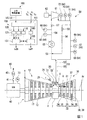
本実施形態のガスタービン設備は、図1に示すように、ガスタービン1と、ガスタービン1の高温部品を冷却するガスタービン冷却系統(以下、単に冷却系統とする)50と、を備えている。
As shown in FIG. 1, the gas turbine equipment of this embodiment includes a
ガスタービン1は、外気Aを圧縮して圧縮空気を生成する空気圧縮機10と、燃料供給源からの燃料Fを圧縮空気中で燃焼させて燃焼ガスGを生成する燃焼器20と、燃焼ガスGにより駆動するタービン30と、を備える。
The
空気圧縮機10は、軸線Arを中心として回転する圧縮機ロータ12と、この圧縮機ロータ12を覆う圧縮機車室17と、を有する。また、タービン30は、軸線Arを中心として回転するタービンロータ32と、このタービンロータ32を覆うタービン車室37と、を有する。圧縮機ロータ12とタービンロータ32とは、同一の軸線Ar上に位置し、互いに連結されてガスタービンロータ2を成す。ガスタービン1は、さらに、圧縮機車室17とタービン車室37との間に配置されている中間車室6を備える。この中間車室6には、燃焼器20が取り付けられている。圧縮機車室17と中間車室6とタービン車室37とは、互いに連結されてガスタービン車室7を成す。なお、以下では、軸線Arが延びる方向を軸方向、軸方向でタービン30に対して空気圧縮機10が存在する側を軸方向上流側、軸方向上流側の反対側を軸方向下流側とする。
The
タービンロータ32は、ロータ軸33と、このロータ軸33に設けられている複数の動翼列34と、を有する。複数の動翼列34は、軸方向に並んでいる。各動翼列34は、それぞれ、軸線Arに対する周方向に並んでいる複数の動翼35を有する。タービン30は、さらに、タービン車室37の内周側に固定されている複数の静翼列38を有する。静翼列38は、いずれかの動翼列34の軸方向上流側に配置されている。各静翼列38は、それぞれ、軸線Arに対する周方向に並んでいる複数の静翼39を有する。タービン車室37の内周側とロータ軸33の外周側との間の環状の空間は、燃焼ガスGが流れる燃焼ガス流路31を形成する。
The turbine rotor 32 includes a rotor shaft 33 and a plurality of rotor blade rows 34 provided on the rotor shaft 33. The plurality of moving blade rows 34 are arranged in the axial direction. Each blade array 34 has a plurality of blades 35 arranged in the circumferential direction with respect to the axis Ar. The
燃焼器20は、燃焼ガスGをタービン30の燃焼ガス流路31に送る燃焼筒22と、この燃焼筒22内に燃料F及び圧縮空気を噴出する燃料噴出器21とを有している。燃料噴出器21には、ここに燃料Fを送る燃料ライン25が接続されている。この燃料ライン25には、ここを流れる燃料Fの流量を調節する燃料弁26が設けられている。
The
ガスタービン1を構成する各種部品のうち、燃焼器20の燃焼筒22、動翼35、及び静翼39は、いずれも燃焼ガスGに曝される高温部品を成す。
Of the various components constituting the
ガスタービンロータ2には、発電機40が接続されている。この発電機40は、遮断器41及び変圧器42を介して電力系統45と電気的に接続されている。
A
冷却系統50は、冷却空気ライン51と、リターンライン56と、昇圧機61と、冷却器63と、吸気弁57と、リターン弁58と、検知器64と、リターン弁58及び吸気弁57の動作を制御する制御装置100と、を備える。
The
冷却空気ライン51は、中間車室6に接続されていると共に、高温部品の一つである燃焼筒22に接続されている。この冷却空気ライン51は、空気圧縮機10から中間車室6内に流入した圧縮空気を燃焼筒22に導く。冷却器63は、冷却空気ライン51中の圧縮空気を冷却して冷却空気にする。この冷却器63は、例えば、冷却空気ライン51中の圧縮空気と冷却媒体とを熱交換させて、この圧縮空気を冷却する熱交換器である。なお、ここでの冷却器63は、熱交換器であるが、例えば、冷却器は、圧縮空気が内部を通るラジエターと、このラジエターに空気を送るファンとを有するものであってもよい。昇圧機61は、冷却空気ライン51中の冷却空気を昇圧する。この昇圧機61は、例えば、遠心圧縮機又は軸流圧縮機である。昇圧機61は、モータ62で駆動する。なお、以下では、冷却空気ライン51中で、中間車室6から昇圧機61までの部分を吸気ライン52、昇圧機61から燃焼筒22までの部分を吐出ライン55とする。さらに、吸気ライン52中で、中間車室6から冷却器63までの部分を未冷却吸気ライン53、冷却器63から昇圧機61までの部分を冷却済み吸気ライン54とする。リターンライン56は、吐出ライン55と未冷却吸気ライン53とを接続する。このリターンライン56は、吐出ライン55中の冷却空気を未冷却吸気ライン53に戻すためのラインである。リターン弁58は、リターンライン56に設けられている。このリターン弁58は、吐出ライン55を流れる冷却空気の流量を調節可能なように弁開度が制御される。吸気弁57は、冷却済み吸気ライン54に設けられている。この吸気弁57は、冷却済み吸気ライン54を流れる冷却空気、つまり昇圧機61が吸い込む冷却空気の流量を調節する。
The cooling
検知器64は、冷却済み吸気ライン54を流れる冷却空気の温度Tiを検知する吸気温度計65と、冷却済み吸気ライン54を流れる冷却空気の圧力Piを検知する吸気圧力計66と、吐出ライン55を流れる冷却空気の温度Toを検知する吐出温度計67,70と、吐出ライン55を流れる冷却空気の圧力Poを検知する吐出圧力計68,71と、吐出ライン55を流れる冷却空気の体積流量Foを検知する吐出流量計69,72と、を有する。吐出温度計67、吐出圧力計68、及び吐出流量計69は、いずれも、吐出ライン55中で、リターンライン56との接続位置よりも燃焼筒22側に設けられている。また、吐出温度計70、吐出圧力計71、及び吐出流量計72は、いずれも、吐出ライン55中で、リターンライン56との接続位置よりも昇圧機61側に設けられている。
The
図2を用いて、冷却系統50から燃焼筒22に供給される冷却空気の流量を制御する方法を以下に説明する。
前述したように、中間車室6から抽気された圧縮空気は、吸気ライン52に設けた冷却器63で冷却され、吸気弁57を経て昇圧機61に吸引される。昇圧機61で昇圧された冷却空気は、一部の冷却空気がリターン弁58を有するリターンライン56から未冷却吸気ライン53に戻され、残りの冷却空気は、吐出ライン55を経て燃焼筒22に供給される。リターンライン56は、昇圧機61がサージ域に入るのを防止するため、昇圧機61の保護のために設けるラインである。昇圧機61の通常運転時における吐出ライン55を流れる冷却空気の流量は、吸気弁57とリターン弁58の制御で調整される。但し、吸気弁57とリターン弁58を独立に制御するのは、相互干渉により制御が不安定になる。そこで、制御弁の相互干渉を避けるため、制御弁に対する弁操作指令を、冷却空気の高負荷流量域と低負荷流量域に区分けして冷却空気の流量制御を行う方法(スプリット制御と呼ぶ)が、一般的である。
A method of controlling the flow rate of the cooling air supplied from the
As described above, the compressed air extracted from the
図2は、吸気弁57とリターン弁58の組み合わせによる吐出ライン55を流れる冷却空気のスプリット制御の考え方を示したものである。
縦軸は、吸気弁57又はリターン弁58の弁開度(%)を示す。横軸は、通常運転時の吸気弁57又はリターン弁58に出力される弁操作指令(%)を示す。なお、ここでの弁操作指令とは、図4を用いて後述するBVO等の弁指令である。但し、この弁操作指令には、RVO2を含まない。実線は、吸気弁57を示し、点線はリターン弁58を示す。図2に示すように、前述した冷却空気の高負荷流量域と低負荷流量域を区分するスプリット点Pは、通常は弁操作指令が50%の点である。スプリット点Pに対して弁操作指令が50%未満の領域は低負荷流量域であり、スプリット点Pに対して弁操作指令が50%以上の領域は高負荷流量域である。なお、スプリット点Pの位置を示す弁操作指令50%は一例であり、この値に限定されない。
FIG. 2 shows the concept of split control of the cooling air flowing through the
The vertical axis indicates the valve opening (%) of the
冷却空気が高負荷流量域の場合は、吸気弁57に対する弁操作指令に基づく弁開度により、吐出ライン55を流れる冷却空気量が調節される(吸気弁制御領域)。なお、この領域では、リターン弁58は全閉となる。すなわち、スプリット点Pより冷却空気量が多い高負荷流量域では、ガスタービン1の負荷の増大と共に冷却空気の必要量が増加するので、弁操作指令の増加と共に、吸気弁57の弁開度が大きくなり、冷却空気量が増加する。ガスタービン1の負荷が減少する場合は、弁操作指令の減少と共に、吸気弁57の弁開度が小さくなり、スプリット点Pで最小開度になる。吸気弁57の最小開度は、通常20%であり、この開度で一定となる。但し、最少開度20%は一例であり、この値に限定されない。
When the cooling air is in a high load flow rate region, the amount of cooling air flowing through the
一方、冷却空気がスプリット点Pより低負荷流量域の場合は、吸気弁57は、最少開度に維持される。ガスタービン1の負荷が減少すると共に、吐出ライン55を流れる冷却空気量を更に減少させるためには、弁操作指令をスプリット点Pから更に小さくする必要がある。しかし、昇圧機61を流れる冷却空気量が低下すると、昇圧機61はサージ域に入るおそれがある。そのため、昇圧機61をサージ現象から保護するため、リターン弁58が開き始める。この領域は、昇圧機61の保護を目的としたアンチサージ制御の領域である。つまり、吐出ライン55を流れる冷却空気量をより小さい流量で調節しつつ、アンチサージの観点から昇圧機61を流れる冷却空気の流量を一定量確保するように、リターン弁58の弁開度が制御される(リターン弁制御領域)。この結果、吐出ライン55を流れる冷却空気量を制御すると共に、昇圧機61を流れる冷却空気量を一定流量確保できるので、昇圧機61のサージ現象が回避される。なお、前述したように、この低負荷流量域では、吸気弁57は最小開度である一定の開度が維持され、吐出ライン55を流れる冷却空気量は、リターン弁58の弁開度で調節される。
On the other hand, when the cooling air is in a low load flow rate region from the split point P, the
次に、昇圧機の体積流量と圧力比の関係について、図3を用いて説明する。
冷却空気の圧力を高める昇圧機61において、昇圧機61が吸い込む冷却空気の体積流量と、昇圧機61の圧力比(=吐出圧/吸気弁の入口圧)と、吸気弁の開度と、の間には、一定の関係がある。
このため、図3に示すように、昇圧機61の特性を示す手段として、体積流量を横軸にとり、圧力比を縦軸にとり、吸気弁の開度をパラメータにとったグラフで、昇圧機61の特性を示すことができる。昇圧機61は、一般的に、体積流量の増加に伴って圧力比が低下する特性を持っている。図3では、吸気弁57の開度をパラメータとして、その開度を変えた異なる3本の特性ラインL1、L2、L3を一例として示している。具体的には、吸気弁の開度100%の時の特性ラインL1(100)、吸気弁の開度50%の時の特性ラインL2(50)、吸気弁の開度20%の時の特性ラインL3(20)である。昇圧機61の圧力比と吸気弁57の開度が定まれば、昇圧機61を流れる冷却空気の体積流量が決定できる。
Next, the relationship between the volume flow rate of the booster and the pressure ratio will be described with reference to FIG.
In the
Therefore, as shown in FIG. 3, as a means for indicating the characteristics of the
昇圧機61は、吸気弁の開度が一定であれば、その開度に応じた特性ライン上の点で運転される。特性ラインL2(50) を一例に挙げて説明する。特性ラインL2(50) 上の運転点X1は、吸気弁57の開度が50%に維持されていれば、特性ラインL2(50) に沿ってこの特性ライン上を移動する。特性ラインL2(50) 上の点で、最も圧力比が高く、最も体積流量が小さい点、すなわち、特性ライン上で圧力比が高い側の端の点Xsは、最も体積流量が小さく、昇圧機61にサージングが発生し得る運転点である。このため、吸気弁57の開度の異なる複数の特性ラインの点Xsを結んだラインは、サージラインLsと呼ばれる。また、サージラインLs に対して、サージング発生点Xsより体積流量で余裕を持たせたラインは、コントロールラインLco と呼ばれる。
If the opening degree of the intake valve is constant, the
昇圧機61は、通常運転時は、負荷指令からの冷却空気の目標流量に基づき運転される。昇圧機61の通常の運転点X1は、コントロールラインLco より体積流量が大きい領域で、吸気弁57の開度に応じた特性ライン上で運転される。燃焼器20の運転条件の変動により、冷却空気の必要流量が低下して、運転点X1がコントロールラインLco上の点X2に達した場合、サージングから昇圧機61を保護するため、昇圧機61は、アンチサージ制御の運転に入る。アンチサージ制御とは、昇圧機61をサージングから保護するため、昇圧機61を流れる冷却空気の流量がコントロールラインLcoから更に低下しないように制御する方法である。具体的には、運転点X1がコントロールラインLcoに達した場合、通常運転時の操作条件とは異なる操作条件が制御装置に与えられ、リターン弁58が開き始める。リターン弁58が開くことにより、昇圧機61を流れる冷却空気の流量が減少することなく一定量確保される。すなわち、昇圧機61の運転点X1が、コントロールラインLcoより体積流量が更に低下して、サージ領域、すなわち、サージラインLsとコントロールラインLcoの間のサージングの発生が高い領域に入ることなく、コントロールライン上に維持されるように、リターン弁58の開度が制御される。
The
昇圧機61の何らかの運転条件の変動で、運転点X1がサージラインLsに達した場合は、リターン弁58は強制的に開とされ、昇圧機61を流れる冷却空気の流量が増加して、昇圧機61のサージングが回避される。
When the operating point X1 reaches the surge line Ls due to a change in the operating conditions of the
なお、コントロールラインLco上のアンチサージ制御の領域で運転されていた昇圧機61は、圧力比が低下して通常運転の領域に入った場合、通常運転時の目標流量に基づき吐出ライン55を流れる冷却空気の流量が調節される。
The
制御装置100は、図4に示すように、受付部101と、基準指令発生部110と、リターン弁指令発生部120と、吸気弁指令発生部140と、リターン弁指令出力部151と、吸気弁指令出力部155と、を有する。
As shown in FIG. 4, the
受付部101は、検知器64で検知された冷却空気の状態量を受け付けると共に、上位制御装置160からの負荷指令LO及び負荷遮断指令LCを受け付ける。ここで、負荷指令LOは、ガスタービン1にかける負荷、言い換えるとガスタービン1の出力を示す指令である。また、負荷遮断とは、ガスタービンロータ2に接続されている発電機40と電力系統45との間の電気的な接続を断つことである。従って、負荷遮断指令LCとは、発電機40と電力系統45との間の電気的な接続を断つ旨を示す指令である。
The accepting
上述の通常運転時の制御装置の構成を以下に説明する。
基準指令発生部110は、目標流量発生部111と、流量偏差演算部113と、PI制御部114と、を有する。目標流量発生部111は、負荷指令LOが示す負荷に応じた昇圧機61の目標流量を求める。この目標流量は、負荷指令LOが示す負荷の変化に対して正の相関性を持って変化する値である。すなわち、負荷指令LOが示す負荷が大きくなると、目標流量も大きくなる。なお、冷却済み吸気ライン54を流れる冷却空気の体積流量を検知する吸気流量計を設け、この吸気流量計からも目標流量を求めてもよい。流量偏差演算部113は、目標流量発生部111で求められた目標流量に対する、吐出流量計72で検知された体積吐出流量の流量偏差Δを求める。PI制御部114は、流量偏差Δに応じた比例・積分動作分を求め、この比例・積分動作分に応じた吸気弁57又はリターン弁58の開度を示す弁操作指令BVOを発生する。しかしながら、この負荷の変化に対して正の相関性を持って変化するパラメータであれば、他のパラメータに応じて昇圧機61の目標流量を定めてもよい。例えば、発電機40の出力計70で検知された出力に応じて目標流量を定めてもよい。また、目標流量の代りに、この目標流量を圧力に換算した目標圧力を用い、この目標圧力と検出された吐出圧力との圧力偏差を求めてもよい。この場合、PI制御部114は、この圧力偏差に応じた比例・積分動作分を求め、この比例・積分動作分に応じた弁操作指令BVOを発生してもよい。
The configuration of the control device during normal operation will be described below.
The reference
リターン弁指令発生部120は、第一弁指令発生部121と、第二弁指令発生部131とを有する。第一弁指令発生部121は、前述した昇圧機61のアンチサージ制御の領域におけるリターン弁58の開度を示す第一弁指令RVO1を発生する。第二弁指令発生部131は、負荷遮断指令LCを受け付けた際に、リターン弁58の開度を予め定められた遮断時開度へ強制的に大きくする旨の弁指令である第二弁指令RVO2を発生する。
The return
第一弁指令発生部121は、昇圧機61のアンチサージ制御を分担し、昇圧機61をサージングから保護するための昇圧機保護指令発生部の役割を果たす。すなわち、昇圧機61の運転点X1がコントロールラインLco に達した場合、通常運転時の操作条件とは異なる目標流量が制御装置に与えられる。第一弁指令発生部121は、吐出流量計72で検出された体積流量Foから算出した吸込流量と目標流量との偏差Δを求め、流量偏差Δに応じた比例・積分動作分を求め、これに応じた開度を示す第一弁指令RVO1を出力する。
The first
第二弁指令発生部131は、直後指令発生部132と、開度減少指令発生部133と、第一条件記憶部134と、第二条件記憶部135と、変化率記憶部136と、タイマー137と、を有する。直後指令発生部132は、負荷遮断指令LCを受け付けた直後に、予め定めた遮断時開度を示す弁指令を第二弁指令RVO2として出力する。変化率記憶部136は、リターン弁58の開度の単位時間当たりの減少量である変化率rが記憶されている。開度減少指令発生部133は、変化率記憶部136に記憶されている変化率rで変化するリターン弁58の開度を示す弁指令を第二弁指令RVO2として出力する。第一条件記憶部134は、負荷遮断指令LCを受け付けてから昇圧機61でのサージング発生の可能性が低くなったと想定される時間である第一時間T1が記憶されている。第二条件記憶部135は、第一時間T1より長い時間である第二時間T2が記憶されている。タイマー137は、負荷遮断指令LCを受け付けてから第一時間T1経過するまでをカウントすると共に、第二時間T2経過するまでをカウントする。直後指令発生部132は、負荷遮断指令LCを受け付けてからタイマー137が第一時間T1の経過を認識するまで、第二弁指令RVO2を発生する。開度減少指令発生部133は、タイマー137が第一時間T1の経過を認識してから第二時間T2の経過を認識するまで、第二弁指令RVO2を出力する。
The second valve
吸気弁指令発生部140は、第一弁指令発生部141と、第三条件記憶部142と、タイマー143と、を有する。第一弁指令発生部141は、負荷遮断指令LCを受け付けた直後に、予め定めた遮断時開度を示す弁指令を第一弁指令SVO1として出力する。第三条件記憶部142は、負荷遮断指令LCを受け付けてから燃焼筒22が十分に冷却されている状態に戻ったと想定される時間である第三時間T3(>T1,T2)が記憶されている。タイマー143は、負荷遮断指令LCを受け付けてから第三時間T3経過するまでをカウントする。第一弁指令発生部141は、負荷遮断指令LCを受け付けてからタイマー143が第三時間T3の経過を認識するまで、第一弁指令SVO1を発生する。
The intake valve
リターン弁指令出力部151は、選択部152と、指令変換部153と、を有する。選択部152は、リターン弁指令発生部120からの第一弁指令RVO1及び第二弁指令RVO2と、基準指令発生部110から基準指令BVOとのうち、いずれか一の指令を選択する。選択部152は、第二弁指令RVO2の他に、第一弁指令RVO1又は基準指令BVOが入力した場合、第二弁指令RVO2を選択する。選択部152は、第一弁指令RVO1と基準指令BVOとが入力した場合、開度として大きな開度を示す指令を選択する。指令変換部153は、選択部152が選択した一の指令をリターン弁58の制御に合ったリターン弁指令RVOに変換して、このリターン弁指令RVOをリターン弁58に出力する。この指令変換部153は、選択部152が選択した一の指令が基準指令BVOの場合、弁指令の指令値が予め定められた値未満のとき、基準指令BVOを、負荷の変化に対して負の相関性を持って変化するリターン弁58の開度を示すリターン弁指令RVOに変換する。弁指令の指令値が予め定められた値以上のとき、基準指令BVOを、弁指令の変化に関わらず一定の開度を示すリターン弁指令RVOに変換する。
The return valve
吸気弁指令出力部155も、選択部156と、指令変換部157と、を有する。選択部156は、吸気弁指令発生部140からの第一弁指令SVO1と、基準指令発生部110から基準指令BVOとのうち、いずれか一の指令を選択する。選択部156は、第一弁指令SVO1と基準指令BVOとが入力された場合、第一弁指令SVO1を選択する。言い換えると、選択部156は、第一弁指令SVO1と基準指令BVOとが入力した場合、開度として大きな開度を示す一の指令を選択する。指令変換部157は、選択部156が選択した一の指令を吸気弁57の制御に合った吸気弁指令SVOに変換して、この吸気弁指令SVOを吸気弁57に出力する。この指令変換部157は、選択部156が選択した一の指令が基準指令BVOの場合、弁指令の指令値が予め定められた値未満のとき、基準指令を、弁指令の変化に関わらず一定の開度を示す吸気弁指令SVOに変換する。弁指令の指令値が予め定められた値以上のとき、基準指令BVOを、弁指令の変化に対して正の相関性を持って変化する吸気弁57の開度を示す吸気弁指令SVOに変換する。
The intake valve
ここで、リターン弁指令出力部151の指令変換部153及び吸気弁指令出力部155の指令変換部157における基準指令BVOの変換形態について、図4を用いて具体的に説明する。ここでは、弁指令に関する前述の予め定められた値を50%とする。なお、弁指令に関する前述の予め定められた値は、リターン弁58の弁特性等に応じて定まる値であるため、この値に限定されない。
Here, the conversion form of the reference command BVO in the
リターン弁指令出力部151の指令変換部153は、弁指令の指令値が予め定められた50%未満の場合、基準指令BVOを、基準指令BVOが示す開度及び弁指令の変化に対して負の相関性を持って変化する開度を示すリターン弁指令RVOに変換する。言い換えると、指令変換部153は、基準指令BVOを、基準指令BVOが示す開度及び弁指令の指令値が増加するに連れてリターン弁58の開度が小さくなるリターン弁指令RVOに変換する。弁指令の指令値が0%の場合、このリターン弁指令RVOが示す開度は例えば100%である。また、弁指令の指令値が50%以上の場合、このリターン弁指令RVOが示す開度は例えば0%で一定である。
When the command value of the valve command is less than 50%, the
吸気弁指令出力部155の指令変換部157は、弁指令の指令値が予め定められた50%以上のとき、基準指令BVOを、基準指令BVOが示す開度及び弁指令の変化に対して正の相関性を持って変化する開度を示す吸気弁指令SVOに変換する。言い換えると、指令変換部157は、この場合、基準指令BVOを、基準指令BVOが示す開度及び弁指令の指令値が増加するに連れて吸気弁57の開度が大きくなる吸気弁指令SVOに変換する。弁指令の指令値が50%の場合、この吸気弁指令SVOが示す開度は例えば20%である。また、弁指令の指令値が50%未満の場合、この吸気弁指令SVOが示す開度は例えば20%で一定である。
The
次に、図5に示すフローチャートに従って、制御装置100の動作について説明する。
Next, the operation of the
検知器64は、常時、冷却空気の状態量を検知し、これを制御装置100に送る(検知工程)。
The
制御装置100の受付部101は、上位制御装置160から負荷指令LO及び負荷遮断指令LCを受け付けると共に、検知器64で検知された冷却空気の状態量を随時受け付ける(S1:受付工程)。
The accepting
制御装置100の基準指令発生部110は、受付部101が受け付けた負荷指令等に応じた基準指令BVOを発生する(S2:基準指令発生工程)。制御装置100のリターン弁指令発生部120は、受付部101が受け付けた状態量等に応じたリターン弁58用の弁指令を発生する(S3:リターン弁指令発生工程)。また、このリターン弁指令発生工程(S3)と並行して、制御装置100の吸気弁指令発生部140は、受付部101が受け付けた状態量等に応じた吸気弁57用の弁指令を発生する(S4:吸気弁指令発生工程)。
The reference
基準指令発生工程(S2)では、基準指令発生部110の目標流量発生部111が、負荷指令LOが示す負荷に応じた昇圧機61の目標流量を発生する。この目標流量は、前述したように、負荷指令LOが示す負荷の変化に対して正の相関性を持って変化する値である。基準指令発生部110の流量偏差演算部113は、吐出流量計69で検知された吐出流量Foと目標流量との偏差Δを求める。基準指令発生部140のPI制御部114は、流量偏差Δに応じた比例・積分動作分を求め、この比例・積分動作分に応じたリターン弁58及び吸気弁57に対する基準指令BVOを発生する。
In the reference command generation step (S2), the target flow
リターン弁指令発生工程(S3)では、前述のように、昇圧機61のアンチサージ制御を分担する。すなわち、図3に示すように、昇圧機61の運転点X1がコントロールラインLcoに達した場合、通常運転時の操作条件とは異なる目標流量が制御装置に与えられる。リターン弁指令発生部120の第一弁指令発生部121は、吐出流量計72で検出された体積流量Foと目標流量との偏差Δを求める。そして、この流量偏差Δに応じた比例・積分動作分を求め、これに応じたリターン弁58の開度を示す弁指令を第一弁指令ROV1として出力する。
In the return valve command generation step (S3), the anti-surge control of the
また、リターン弁指令発生工程(S3)では、受付部101が負荷遮断指令LCを受け付けると、リターン弁58用の第二弁指令発生部131がリターン弁58用の第二弁指令RVO2を発生する(S3b:第二弁指令発生工程)。なお、この第二弁指令発生工程(S3b)の詳細については後述する。
In the return valve command generation step (S3), when the receiving
吸気弁指令発生工程(S4)では、受付部101が負荷遮断指令LCを受け付けると、吸気弁57用の第一弁指令発生部141が予め記憶されている遮断時開度を示す第一弁指令SVO1を発生する(S4a:第一弁指令発生工程)。この遮断時開度は、例えば、吸気弁57の全開の開度である。なお、遮断時開度は、第一弁指令SVO1を発生した時点での基準指令BVOに基づく吸気弁指令SVOが示す開度よりも大きな開度であればよく、例えば、開度90%であってもよい。
In the intake valve command generation step (S4), when the receiving
リターン弁指令出力部151は、リターン弁指令RVOをリターン弁58に出力する(S5:リターン弁指令出力工程)。吸気弁指令出力部155は、吸気弁指令SVOを吸気弁57に出力する(S6:吸気弁指令出力工程)。
The return valve
リターン弁指令出力工程(S5)では、リターン弁指令出力部151の選択部152が、リターン弁58に関する第一弁指令RVO1、第二弁指令RVO2、基準指令BVOのうち、いずれか一の指令を選択する(S5a:選択工程)。選択部152は、いずれか複数の指令を受け付けると、基本的に、複数の指令のうち、リターン弁58の開度として最も大きな開度を示す指令を選択する。リターン弁指令出力工程(S5)では、さらに、リターン弁指令出力部151の指令変換部153が、選択工程(S5a)で選択された一の指令をリターン弁58の制御にあったリターン弁指令RVOに変換して、このリターン弁指令RVOをリターン弁58に出力する(S5b:指令変換工程)。
In the return valve command output step (S5), the
吸気弁指令出力工程(S6)では、吸気弁指令出力部155の選択部156が、吸気弁57に関する第一弁指令SVO1と基準指令BVOとのうち、いずれかの一の指令を選択する(S6a:選択工程)。選択部156は、いずれか複数の指令を受け付けると、複数の指令のうち、吸気弁57の開度として大きな開度を示す指令を選択する。吸気弁指令出力工程(S6)では、さらに、吸気弁指令出力部155の指令変換部157が、選択工程(S6a)で選択された一の指令を吸気弁57の制御にあった吸気弁指令SVOに変換して、この吸気弁指令SVOを吸気弁57に出力する(S6b:指令変換工程)。
In the intake valve command output step (S6), the
例えば、図3に示すように、昇圧機61の運転点X1,X3が、コントロールラインLcoより圧力比が低く且つ体積流量が多い側に位置し、且つリターン弁指令発生部120が第二弁指令RVO2を発生していない場合、リターン弁指令出力工程(S5)における選択工程(S5a)では、リターン弁58に関する第一弁指令RVO1と基準指令BVOとのうち、基準指令BVOを選択する。また、昇圧機61の運転点X1,X3がコントロールラインLcoより圧力比が低く且つ体積流量が多い側に位置し、且つ吸気弁指令発生部140が第一弁指令SVO1を発生していない場合、吸気弁指令出力工程(S6)における選択工程(S6a)では、基準指令BVOを選択する。
For example, as shown in FIG. 3, the operating points X1 and X3 of the
基準指令BVOに基づくリターン弁指令RVOがリターン弁58に出力されると、リターン弁58の開度は、このリターン弁指令RVOが示す開度になる。基準指令BVOに基づくリターン弁指令RVOが示す開度は、図2を用いて前述したように、弁指令の指令値が0%の場合、例えば100%で、弁指令の指令値が50%に近づくに連れて次第に小さくなり、弁指令の指令値が50%であると、例えば0%になる。弁指令の指令値が大きくなるに連れて、リターン弁58の開度が小さくなると、リターンライン56を流れる冷却空気が少なくなり、逆に、吐出ライン55を流れる冷却空気が多くなる。よって、弁指令の指令値が50%未満の場合、指令値が大きくなるに連れて、リターン弁58の開度が小さくなり、燃焼筒22に供給される冷却空気の流量が多くなる。一方、弁指令の指令値が50%以上になると、指令値が大きくなっても、リターン弁58の開度が例えば0%に維持される。
When the return valve command RVO based on the reference command BVO is output to the
基準指令BVOに基づく吸気弁指令SVOが吸気弁57に出力されると、吸気弁57の開度は、この吸気弁指令SVOが示す開度になる。基準指令BVOに基づく吸気弁指令SVOが示す開度は、図2を用いて前述したように、弁指令の指令値が50%未満の場合、例えば20%で一定である。また、弁指令の指令値が50%以上の場合、基準指令BVOに基づく吸気弁指令SVOが示す開度は、指令値が大きくなるに連れて、次第に大きくなる。吸気弁57の開度が大きくなると、吐出ライン55を流れる冷却空気が多くなる。よって、弁指令の指令値が50%以上の場合、負荷が大きくなるに連れて、吸気弁57の開度が大きくなり、燃焼筒22に供給される冷却空気の流量が多くなる。
When the intake valve command SVO based on the reference command BVO is output to the
以上のように、本実施形態では、昇圧機61の運転点が、コントロールラインLcoより圧力比が低く且つ体積流量が多い側に位置し、且つ弁指令の指令値が50%未満の場合、指令値が大きくなるに連れて、リターン弁58の開度を小さくして、燃焼筒22に供給される冷却空気の流量を多くする。また、本実施形態では、昇圧機61の運転点が、コントロールラインLcoより圧力比が低く且つ体積吸気流量が多い側に位置し、且つ弁指令の指令値が50%以上の場合、指令値が大きくなるに連れて、吸気弁57の開度を大きくして、燃焼筒22に供給される冷却空気の流量を多くする。
As described above, in this embodiment, when the operating point of the
図3に示すように、昇圧機61の運転点X1、X3がコントロールラインLco に達した場合、昇圧機61はアンチサージ制御の運転に入り、通常運転時の操作条件とは異なる目標流量が制御装置に与えられ、リターン弁58の開度が開く方向の第一弁指令RVO1を発生する。このため、第一弁指令RVO1が示す開度は基準指令BVOが示す開度より大きくなる。よって、リターン弁指令出力工程(S5)における選択工程(S5a)では、第一弁指令RVO1と基準指令BVOとを受け付けても、大きな開度を示す第一弁指令RVO1を選択する。リターン弁指令出力工程(S5)における指令変換工程(S5b)では、この第一弁指令RVO1をリターン弁58の制御に合ったリターン弁指令RVOに変換して、このリターン弁指令RVOをリターン弁58に出力する。
As shown in FIG. 3, when the operating points X1 and X3 of the
なお、弁指令の指令値が50%未満の場合も、50%以上の場合も、昇圧機61の運転点がコントロールラインLco上、又はサージ領域内に位置するようになり、昇圧機61でサージングの発生が高まると、リターン弁指令発生部120からのリターン弁58の開度を大きくする第一弁指令RVO1に基づくリターン弁指令RVOがリターン弁58に出力される。
In addition, when the command value of the valve command is less than 50% or more than 50%, the operating point of the
一方、昇圧機61でサージングの発生が高まっても、吸気弁指令出力工程(S6)では、吸気弁指令発生工程(S4)で第一弁指令SVO1が発生されない限り、基準指令BVOに基づく吸気弁指令SVOが吸気弁57に出力される。
On the other hand, even if surging increases in the
第一弁指令RVO1に基づくリターン弁指令RVOがリターン弁58に出力されると、リターン弁58の開度が大きくなり、リターンライン56を流れる冷却空気の流量が多くなる。この結果、燃焼筒22に供給される冷却空気の流量は多くならないものの、昇圧機61を通過する冷却空気の流量が多くなる上に、昇圧機61の圧力比が小さくなる。このため、昇圧機61でのサージング発生が抑えられる。
When the return valve command RVO based on the first valve command RVO1 is output to the
以上のように、本実施形態では、昇圧機61の運転点X1、X3がコントロールラインLco上の点X2、X4、又はサージ領域内に位置するようになり、昇圧機61でサージング発生が高まった場合、専ら、リターン弁58の開度が制御されて、サージング発生が抑えられる。
As described above, in the present embodiment, the operating points X1 and X3 of the
ところで、負荷遮断指令LCが出力されると、上位制御装置160等からの指示で遮断器41が開き、発電機40と電力系統45との間の電気的接続が断たれる。さらに、上位制御装置160等からの指示で燃料弁26が閉じ、燃焼器20への燃料供給が断たれる。この結果、負荷遮断時には、空気圧縮機10の吐出圧が急激に低下する。このため、昇圧機61の吸気圧も、空気圧縮機10の吐出圧の急激な低下に伴って、急激に低下する。一方、昇圧機61の吐出圧は、冷却空気ライン51の存在により、空気圧縮機10の吐出圧の低下に対して遅れて低下する。このため、負荷遮断直後では、一時的に、昇圧機61の圧力比が高まる。よって、負荷遮断時には、昇圧機61でのサージング発生の可能性が急激に高まる。
By the way, when the load interruption command LC is output, the
負荷遮断時、昇圧機61でのサージング発生の可能性が高まるため、リターン弁58に関する第一弁指令RVO1が示す開度も大きくなる。リターン弁指令発生部120の第一弁指令発生部121は、負荷遮断後に検知器64によって検知された各種状態量に応じて、第一弁指令RVO1を発生する。このため、リターン弁指令発生部120の第一弁指令発生部121は、負荷遮断が発生した場合、昇圧機61の運転点X1、X3がコントロールラインLcoに達して初めて第一弁指令RVO1を発生し、サージラインLsに達してリターン弁58を強制的に開とする第一弁指令RVO1を発生する。この結果、昇圧機61のサージングを回避できるが、応答性が悪い。
When the load is interrupted, the possibility of occurrence of surging in the
そこで、リターン弁指令発生工程(S3)では、受付部101が負荷遮断指令LCを受け付けると、検知器64によって検知された各種状態量に関わらず、前述したように、直ちに、リターン弁58用の第二弁指令発生部131がリターン弁58用の第二弁指令RVO2を発生する(S3b:第二弁指令発生工程)。リターン弁指令出力工程(S5)における選択工程(S5a)では、第二弁指令RVO2が発生すると、他の指令に優先して、この第二弁指令RVO2を選択する。リターン弁指令出力工程(S5)における指令変換工程(S5b)では、この第二弁指令RVO2をリターン弁58の制御に合ったリターン弁指令RVOに変換して、このリターン弁指令RVOをリターン弁58に出力する。
Therefore, in the return valve command generation step (S3), when the receiving
本実施形態では、受付部101が負荷遮断指令LCを受け付けると、負荷指令が示す負荷の値に関係なく、リターン弁指令出力工程(S5)では、第二弁指令RVO2に基づくリターン弁指令RVOをリターン弁58に出力する。
In the present embodiment, when the receiving
リターン弁58用の第二弁指令発生工程(S3b)では、負荷遮断指令LCを受けると、直ちに、直後指令発生部132が予め記憶されている遮断時開度を示す第二弁指令RVO2を発生する。この遮断時開度は、例えば、リターン弁58の全開の開度である。なお、遮断時開度は、第二弁指令RVO2を発生した時点での第一弁指令RVO1が示す開度よりも大きな開度であればよく、例えば、開度90%であってもよい。
In the second valve command generation step (S3b) for the
このため、図6に示すように、受付部101が負荷遮断指令LCを受け付けると(t0)、リターン弁58の開度は、直ちに、遮断時開度まで大きくなる。
For this reason, as shown in FIG. 6, when the receiving
リターン弁58用の第二弁指令発生工程(S3b)では、タイマー137により、受付部101が負荷遮断指令LCを受け付けたときからの時間がカウントされる。直後指令発生部132は、図6に示すように、受付部101が負荷遮断指令LCを受け付けたとき(t0)から、タイマー137によりカウントされた時間が第一時間T1に至るまで、遮断時開度を示す第二弁指令RVO2を発生し続ける。
In the second valve command generation step (S3b) for the
タイマー137によりカウントされた時間が第一時間T1に至ると、直後指令発生部132は、遮断時開度を示す第二弁指令RVO2の発生を中止する。この替りに、タイマー137によりカウントされた時間が第一時間T1に至ると、開度減少指令発生部133が第二弁指令RVO2を発生する。開度減少指令発生部133は、遮断時開度と、変化率記憶部136に記憶されている変化率rとを用いて、第一時間T1経過後の各時刻におけるリターン弁58の開度を示す第二弁指令RVO2を発生する。すなわち、開度減少指令発生部133は、遮断時開度から一定の変化率rで開度が小さくなる第二弁指令RVO2を発生する。この閉側への変化率rは、サージング発生の可能性が低下しているときの第一弁指令RVO1が示す開度の閉側への最大変化率より大きい。
When the time counted by the
開度減少指令発生部133は、タイマー137によりカウントされた時間が第二時間T2(>T1)に至るまで、第二弁指令RVO2を発生する。タイマー137によりカウントされた時間が第二時間T2に至ると、開度減少指令発生部133は、第二弁指令RVO2の発生を中止する。
The opening degree reduction
リターン弁指令出力工程(S5)では、第二弁指令発生部131の直後指令発生部132及び開度減少指令発生部133から第二弁指令RVO2が発生している間、この第二弁指令RVO2に基づくリターン弁指令RVOをリターン弁58に出力する。この結果、図6に示すように、タイマー137によりカウントされた時間が第一時間T1に至ってから第二時間に至るまで、リターン弁58の開度は、一定の変化率rで小さくなる。
In the return valve command output step (S5), the second valve command RVO2 is generated while the second valve command RVO2 is generated immediately after the second
第二弁指令発生部131の直後指令発生部132及び開度減少指令発生部133が第二弁指令RVO2の発生を中止した時点、つまり、受付部101が負荷遮断指令LCを受け付けたときから第二時間T2経過した時点では、昇圧機61でのサージング発生の可能性が低くなっている。このため、この時点でのリターン弁58に関する第一弁指令RVO1が示す開度よりも、基準指令BVOが示す開度の方が大きくなる。よって、リターン弁指令出力工程(S5)における選択工程(S5a)では、第一弁指令RVO1と基準指令BVOとのうち、基準指令BVOを選択する。リターン弁指令出力工程(S5)における指令変換工程(S5b)では、この基準指令BVOに基づくリターン弁指令RVOをリターン弁58に出力する。
Immediately after the second valve
負荷遮断時における昇圧機61でのサージング発生を抑えるという観点からは、受付部101が負荷遮断指令LCを受け付けた後、リターン弁58の開度を遮断時開度にし、その後も、遮断時開度を維持し続けていても何ら支障はない。しかしながら、リターン弁58の開度を遮断時開度にすると、昇圧機61から吐出ライン55を経て燃焼筒22に供給される冷却空気の流量が減少し、燃焼筒22が焼損するおそれがある。
From the viewpoint of suppressing the occurrence of surging in the
そこで、本実施形態では、負荷遮断指令LCを受け付けてから昇圧機61でのサージング発生の可能性が低くなったと想定される第一時間T1が経過すると、リターン弁58の開度を一定の変化率rで小さくしている。この結果、昇圧機61から吐出ライン55を経て燃焼筒22に供給される冷却空気の流量が増加し、燃焼筒22の焼損を抑えることができる。特に、本実施形態では、リターン弁58の閉側への変化率rが、サージング発生の可能性が低下しているときの第一弁指令RVO1が示す開度の閉側への最大変化率より大きいため、リターン弁58の開度が急激に小さくなる。このため、本実施形態では、燃焼筒22に供給される冷却空気の流量が負荷遮断直後に一時的に少なくなるものの、この冷却空気の流量が急激に回復する。よって、本実施形態では、燃焼筒22の焼損をより抑えることができる。
Therefore, in the present embodiment, when the first time T1 when it is assumed that the possibility of the occurrence of surging in the
吸気弁指令発生工程(S4)における第一弁指令発生工程(S4a)では、受付部101が負荷遮断指令LCを受け付けると、検知器64によって検知された各種状態量に関わらず、前述したように、直ちに、吸気弁57用の第一弁指令発生部141が吸気弁57用の第一弁指令SVO1を発生する。吸気弁指令出力工程(S6)における選択工程(S6a)では、この第一弁指令SVO1が発生すると、他の指令に優先して、この第一弁指令SVO1を選択する。吸気弁指令出力工程(S6)における指令変換工程(S6b)では、この第一弁指令SVO1を吸気弁57の制御に合った吸気弁指令SVOに変換して、この吸気弁指令SVOを吸気弁57に出力する。この結果、吸気弁57は、図6に示すように、受付部101が負荷遮断指令LCを受け付けると(t0)、直ちに、遮断時開度、この場合は全開になる。よって、昇圧機61を流れる冷却空気の体積流量が急激に増加する。このため、本実施形態では、この吸気弁57の動作によっても、負荷遮断時におけるサージング発生を抑えることができる。また、本実施形態では、吸気弁57の強制開により、昇圧機61を流れる冷却空気の体積流量が急激に増加すると共に、吐出ライン55を経て燃焼筒22に供給される冷却空気の体積流量も増加するので、燃焼筒22の焼損を抑えることができる。特に、本実施形態では、リターン弁58が遮断時開度になったことに起因した、燃焼筒22に供給される冷却空気流量の減少を、この吸気弁57の強制開により相殺することできる。よって、本実施形態では、この観点からも、燃焼筒22の焼損を抑えることができる。
In the first valve command generation step (S4a) in the intake valve command generation step (S4), when the receiving
吸気弁57の第一弁指令発生工程(S4a)では、タイマー143により、受付部101が負荷遮断指令LCを受け付けたときからの時間がカウントされる。第一弁指令発生工程(S4a)では、図6に示すように、受付部101が負荷遮断指令LCを受け付けたときから(t0)、タイマー143によりカウントされた時間が第三時間T3(>T2)に至るまで、遮断時開度を示す第一弁指令SVO1を発生し続ける。吸気弁57の第一弁指令発生工程(S4a)では、タイマー143によりカウントされた時間が第三時間T3に至ると、第一弁指令SVO1の発生を中止する。吸気弁57の第一弁指令発生工程(S4a)での第一弁指令SVO1の発生が中止されると、つまり、受付部101が負荷遮断指令LCを受け付けたときから第三時間(T3)経過すると、吸気弁指令出力工程(S6)では、基準指令BVOに基づく吸気弁指令SVOを吸気弁57に出力する。
In the first valve command generation step (S4a) of the
以上のように、本実施形態では、負荷遮断時における昇圧機61のサージング発生の可能性を低下させつつ、高温部品である燃焼筒22を冷却することができる。
As described above, in the present embodiment, the
なお、本実施形態では、昇圧機61でのサージング発生の可能性が低くなったとされる予め定められている第一条件として、第一時間T1を採用している。しかしながら、この第一条件としては、検知器64で検知された状態量により定まる昇圧機61の現状の運転点が、サージング発生の可能性が低い領域に至ることを条件としてもよい。すなわち、第一条件は、昇圧機61でのサージング発生の可能性が低くなったとされる条件であれば、如何なる条件でもよい。また、本実施形態では、第二条件として、第二時間T2を採用している。しかしながら、この第二条件としては、吐出流量計69で検知される吐出流量が第一条件を満たした時点における吐出流量よりも多い流量に至ることを条件としてもよい。
Note that, in the present embodiment, the first time T1 is adopted as the first condition that is determined in advance that the possibility of surging occurring in the
「変形例」
以上で説明したガスタービン設備の一実施形態の変形例について、図7を参照して詳細に説明する。
"Modification"
A modification of the embodiment of the gas turbine equipment described above will be described in detail with reference to FIG.
本変形例のガスタービン設備は、制御装置100aの構成が上記実施形態における制御装置100の構成と異なることを除いて、上記実施形態のガスタービン設備と同じである。よって、以下では、本変形例の制御装置100aについて説明する。
The gas turbine equipment of this modification is the same as the gas turbine equipment of the above embodiment except that the configuration of the
本変形例の制御装置100aも、上記実施形態の制御装置100と同様、受付部101と、基準指令発生部110と、リターン弁指令発生部120aと、吸気弁指令発生部140と、リターン弁指令出力部151と、吸気弁指令出力部155と、を有する。リターン弁指令発生部120aは、上記実施形態におけるリターン弁指令発生部120と同様に、第一弁指令発生部121と、第二弁指令発生部131aとを有する。第二弁指令発生部131aは、上記実施形態における第二弁指令発生部131と同様、直後指令発生部132と、開度減少指令発生部133aと、タイマー137と、第一条件記憶部134と、第二条件記憶部135aと、を有する。但し、本変形例の開度減少指令発生部133aは、上記実施形態の開度減少指令発生部133と異なる。また、本変形例の第二条件記憶部135aには、上記実施形態の第二条件記憶部135と異なり、予め定められた吐出流量Q2が第二条件として記憶されている。
Similarly to the
本変形例の開度減少指令発生部133aは、圧力比演算部211と、目標流量発生部212と、流量演算部213と、流量偏差演算部214と、PI制御部215と、を有する。
圧力演算部211は、吸気圧力計66、吐出圧力計71で検知された吸気圧Pi、吐出圧Poから圧力比を求める。目標流量発生部212は、昇圧機61の圧力比に対する体積吸気流量を求める。流量演算部213は、吸気温度Ti、吸気圧Pi、吐出温度To、吐出圧Po、吐出流量計72で検知された体積流量Foを用いて、昇圧機61の体積吸気流量を求める。流量偏差演算部214は、目標流量に対する体積吸気流量との偏差Δを求める。PI制御部215は、流量偏差Δに応じたリターン弁58の比例・積分動作分の開度補正量を求め、第二弁指令RVO2を発生する。
The degree-of-opening reduction
The
但し、開度減少指令発生部133aのPI制御部215における比例ゲイン及び積分ゲインは、基準指令発生部110のPI制御部114における比例ゲイン及び積分ゲインと異なっている。具体的には、このPI制御部215により求められる比例・積分動作分の開度補正量が、基準指令発生部110のPI制御部114により求められる比例・積分動作分の開度補正量よりも、大きくなるよう、このPI制御部215における比例ゲイン及び積分ゲインが設定されている。
However, the proportional gain and integral gain in the
本変形例でも、タイマー137によりカウントされた時間が第一時間T1に至ると、開度減少指令発生部133aが第二弁指令RVO2を発生する。タイマー137によりカウントされた時間が第一時間T1になった時点でのリターン弁58の開度は、遮断時開度である。また、タイマー137によりカウントされた時間が第一時間T1になった時点では、昇圧機61でのサージング発生の可能性が低くなっている。このため、開度減少指令発生部133aは、時間経過に伴って次第に小さくなる開度を示す第二弁指令RVO2を発生する。リターン弁指令出力部151は、上記実施形態と同様、直後指令発生部132及び開度減少指令発生部133aからの第二弁指令RVO2に基づくリターン弁指令RVOをリターン弁58に出力する。
Also in this modified example, when the time counted by the
本変形例では、第一時間T1経過後において、目標流量発生部212が求める目標流量、及び/又は流量演算部213が求める体積吸気流量が変化すると、流量偏差演算部214が求める流量偏差Δが変化する。この流量偏差Δが変化すると、PI制御部215が求めるリターン弁58の比例・積分動作分の開度補正量も変化するため、第一時間T1経過後のリターン弁58の開度変化率が一定ではない。よって、本変形例では、上記実施形態のように、受付部101が負荷遮断指令LCを受け付けたときから第二時間T2経過しても、高温部品に送られる冷却空気の流量が高温部品の冷却に十分でない場合がある。また、逆に、受付部101が負荷遮断指令LCを受け付けたときから第二時間T2経過する前に、高温部品に送られる冷却空気の流量が高温部品の冷却に十分になる場合もある。そこで、本変形例では、第二条件記憶部135aには、第二条件として、高温部品の冷却に十分な予め定めた吐出流量Q2が記憶されている。
In the present modification, when the target flow rate calculated by the target flow
開度減少指令発生部133aは、吐出流量計72で検知された吐出流量が第二条件記憶部135aに記憶されている吐出流量Q2になると、第二弁指令RVO2の発生を中止する。リターン弁指令出力部151は、上記実施形態と同様、開度減少指令発生部133aが第二弁指令RVO2の発生を中止すると、基準指令BVOに基づくリターン弁指令RVOをリターン弁58に出力する。
When the discharge flow rate detected by the
以上のように、本変形例でも、負荷遮断指令LCを受け付けてから昇圧機61でのサージング発生の可能性が低くなったと想定される第一時間T1が経過すると、リターン弁58の開度が小さくなる。この結果、本変形例でも、昇圧機61から吐出ライン55を経て燃焼筒22に供給される冷却空気の流量が、負荷遮断後には減少するものの、第一時間T1が経過すると、この冷却空気の流量が増加し、燃焼筒22の焼損を抑えることができる。
As described above, even in the present modification, when the first time T1 that is assumed to have decreased the possibility of occurrence of surging in the
前述したように、開度減少指令発生部133aのPI制御部215における比例ゲイン及び積分ゲインは、PI制御部215により求められる比例・積分動作分の開度補正量が、基準指令発生部110のPI制御部114により求められる比例・積分動作分の開度補正量よりも、大きくなるよう設定されている。このため、開度減少指令発生部133aからの第二弁指令RVO2で定まるリターン弁58の閉側への変化率は、サージング発生の可能性が低下しているときの基準指令BVOで定まる開度の閉側への最大変化率より大きくなる。従って、本変形例でも、上記実施形態と同様、第一時間T1経過後、リターン弁58の開度は急激に小さくなる。このため、本変形例でも、負荷遮断直後に低下した冷却空気の流量が急激に回復する。
As described above, the proportional gain and the integral gain in the
「その他の変形例」
上記実施形態及び上記変形例において、制御装置100,100aと上位制御装置160とは別体であるが、これらは一体であってもよい。
"Other variations"
In the embodiment and the modified example, the
上記実施形態及び上記変形例の冷却系統50は、高温部品としての燃焼筒22に冷却空気を送る。しかしながら、冷却系統50は、高温部品であれば、燃焼筒22以外の部品に冷却空気を送ってもよい。例えば、タービン30の動翼35や静翼39に冷却空気を送ってもよい。
The
1:ガスタービン、2:ガスタービンロータ、6:中間車室、7:ガスタービン車室、10:空気圧縮機、12:圧縮機ロータ、17:圧縮機車室、20:燃焼器、21:燃料噴出器、22:燃焼筒、25:燃料ライン、26:燃料弁、30:タービン、31:燃焼ガス流路、32:タービンロータ、33:ロータ軸、34:動翼列、35:動翼、37:タービン車室、38:静翼列、39:静翼、40:発電機、41:遮断器、50:ガスタービン冷却系統、51:冷却空気ライン、52:吸気ライン、53:未冷却吸気ライン、54:冷却済み吸気ライン、55:吐出ライン、56:リターンライン、57:吸気弁、58:リターン弁、61:昇圧機、63:冷却器、64:検知器、65:吸気温度計、66:吸気圧力計、67,70:吐出温度計、68,71:吐出圧力計、69,72:吐出流量計、100,100a:制御装置、101:受付部、120、120a:リターン弁指令発生部、121:第一弁指令発生部、131、131a:第二弁指令発生部、132:直後指令発生部、133、133a:開度減少指令発生部、137:タイマー、140:吸気弁指令発生部、141:第一弁指令発生部、143:タイマー、110:基準指令発生部、151:リターン弁指令出力部、152,156:選択部、153,157:指令変換部、155:吸気弁指令出力部、160:上位制御装置 1: Gas turbine, 2: Gas turbine rotor, 6: Intermediate casing, 7: Gas turbine casing, 10: Air compressor, 12: Compressor rotor, 17: Compressor casing, 20: Combustor, 21: Fuel Ejector, 22: combustion cylinder, 25: fuel line, 26: fuel valve, 30: turbine, 31: combustion gas flow path, 32: turbine rotor, 33: rotor shaft, 34: blade row, 35: blade 37: turbine casing, 38: stationary blade row, 39: stationary blade, 40: generator, 41: circuit breaker, 50: gas turbine cooling system, 51: cooling air line, 52: intake line, 53: uncooled intake air 54, cooled intake line, 55: discharge line, 56: return line, 57: intake valve, 58: return valve, 61: booster, 63: cooler, 64: detector, 65: intake thermometer, 66: Intake pressure gauge, 67, 70: Exhalation Outlet thermometer, 68, 71: Discharge pressure gauge, 69, 72: Discharge flow meter, 100, 100a: Control device, 101: Reception unit, 120, 120a: Return valve command generation unit, 121: First valve command generation unit 131, 131a: Second valve command generator, 132: Immediate command generator, 133, 133a: Opening reduction command generator, 137: Timer, 140: Intake valve command generator, 141: First valve command generator 143: timer 110: reference command generation unit 151: return valve command output unit 152, 156: selection unit 153, 157: command conversion unit 155: intake valve command output unit 160: host control device
Claims (27)
前記冷却空気ライン中の前記圧縮空気を冷却して冷却空気にする冷却器と、
前記冷却空気ライン中の前記冷却空気を昇圧する昇圧機と、
前記冷却空気ライン中で前記昇圧機よりも前記高温部品側のラインである吐出ライン中の前記冷却空気を前記冷却空気ライン中で前記昇圧機よりも前記空気圧縮機側の吸気ラインに戻すリターンラインと、
前記リターンラインに設けられ、前記リターンラインを流れる前記冷却空気の流量を調節するリターン弁と、
前記吸気ラインを流れる前記冷却空気の状態量と前記吐出ラインを流れる前記冷却空気の状態量とを検知する検知器と、
前記リターン弁の開度を制御する制御装置と、
を備え、
前記制御装置は、
前記ガスタービンの負荷遮断を示す負荷遮断指令を受け付ける受付部と、
前記検知器で検知された前記状態量に応じた前記リターン弁の開度を示す第一弁指令を発生する第一弁指令発生部と、
前記受付部が前記負荷遮断指令を受け付けると、前記検知器で検知された前記状態量に関わらず、前記リターン弁の開度を前記第一弁指令が示す開度以上の予め定められた遮断時開度へ強制的に大きくする旨の弁指令を第二弁指令として発生する第二弁指令発生部と、
前記第二弁指令発生部が前記第二弁指令を発生している場合、前記第二弁指令に基づくリターン弁指令を前記リターン弁に出力し、前記第二弁指令発生部が前記第二弁指令を発生していない場合、前記ガスタービンの状態に応じて前記第一弁指令に基づくリターン弁指令を前記リターン弁に出力するリターン弁指令出力部と、
を有する、
ガスタービン冷却系統。 A cooling air line for directing compressed air compressed by a gas turbine air compressor to a hot part in contact with the combustion gas in the gas turbine;
A cooler that cools the compressed air in the cooling air line into cooling air;
A booster that pressurizes the cooling air in the cooling air line;
A return line for returning the cooling air in the discharge line, which is a line on the high temperature parts side of the booster in the cooling air line, to the intake line on the air compressor side of the booster in the cooling air line. When,
A return valve provided in the return line for adjusting a flow rate of the cooling air flowing through the return line;
A detector for detecting a state quantity of the cooling air flowing through the intake line and a state quantity of the cooling air flowing through the discharge line;
A control device for controlling the opening degree of the return valve;
With
The control device includes:
A receiving unit for receiving a load cutoff command indicating a load cutoff of the gas turbine;
A first valve command generating unit that generates a first valve command indicating an opening degree of the return valve according to the state quantity detected by the detector;
When the accepting unit accepts the load shedding command, blocking the irrespective to the state quantity detected by the detector, the opening degree of the return valve is the first valve command was previously constant because the more the opening indicated A second valve command generating section for generating a valve command for forcibly increasing the hour opening as a second valve command;
When the second valve command generator generates the second valve command, a return valve command based on the second valve command is output to the return valve, and the second valve command generator generates the second valve command. When no command is generated, a return valve command output unit that outputs a return valve command based on the first valve command to the return valve according to a state of the gas turbine;
Having
Gas turbine cooling system.
前記遮断時開度は、前記リターン弁の全開の開度である、
ガスタービン冷却系統。 The gas turbine cooling system according to claim 1,
The shut-off opening is a fully open opening of the return valve.
Gas turbine cooling system.
前記第二弁指令発生部は、前記受付部が前記負荷遮断指令を受け付けると、前記昇圧機のサージング発生の可能性が低くなったとされる予め定められている条件が満たされるまで、前記遮断時開度を維持する旨の弁指令を前記第二弁指令として発生する、
ガスタービン冷却系統。 In the gas turbine cooling system according to claim 1 or 2,
When the receiving unit receives the load cutoff command, the second valve command generating unit is in the cutoff state until a predetermined condition that the possibility of occurrence of surging of the booster is reduced is satisfied. A valve command for maintaining the opening is generated as the second valve command.
Gas turbine cooling system.
前記第二弁指令発生部は、前記予め定められた条件が満たされると、前記リターン弁の開度を前記遮断時開度から小さくする旨の弁指令を前記第二弁指令として発生する、
ガスタービン冷却系統。 In the gas turbine cooling system according to claim 3,
The second valve command generator generates, as the second valve command, a valve command for reducing the opening of the return valve from the shut-off opening when the predetermined condition is satisfied.
Gas turbine cooling system.
前記第一弁指令発生部は、前記検知器で検知された前記状態量がサージング発生の可能性が高まっていることを示す場合、前記リターン弁の開度が大きくなる開度を示す前記第一弁指令を発生し、前記検知器で検知された前記状態量がサージング発生の可能性が低下していることを示す場合、前記リターン弁の開度が小さくなる開度を示す前記第一弁指令を発生し、
前記予め定められた条件が満たされたときの前記第二弁指令が示す開度の閉側への変化率は、サージング発生の可能性が低下しているときの前記第一弁指令が示す開度の閉側への最大変化率より大きい、
ガスタービン冷却系統。 The gas turbine cooling system according to claim 4,
The first valve command generation unit indicates the opening degree at which the opening degree of the return valve is increased when the state quantity detected by the detector indicates that the possibility of occurrence of surging is increased. The first valve command indicating an opening that reduces the opening of the return valve when a valve command is generated and the state quantity detected by the detector indicates that the possibility of occurrence of surging is reduced Occur and
The rate of change of the opening indicated by the second valve command when the predetermined condition is satisfied to the closed side is the opening rate indicated by the first valve command when the possibility of surging is reduced. Greater than the maximum rate of change to the closing side of the degree,
Gas turbine cooling system.
前記予め定められた条件が満たされたときの前記第二弁指令が示す開度の変化率は、予め定められた変化率である、
ガスタービン冷却系統。 In the gas turbine cooling system according to claim 4 or 5,
The rate of change of the opening indicated by the second valve command when the predetermined condition is satisfied is a predetermined rate of change.
Gas turbine cooling system.
前記第二弁指令発生部は、前記予め定められた条件が満たされたとき、前記検知器で検知された前記状態量に応じて定めた開度を示す弁指令を前記第二弁指令として発生する、
ガスタービン冷却系統。 In the gas turbine cooling system according to claim 4 or 5,
The second valve command generator generates, as the second valve command, a valve command indicating an opening determined according to the state quantity detected by the detector when the predetermined condition is satisfied. To
Gas turbine cooling system.
前記予め定められている条件である第一条件が満たされた後、第二条件が満たされると、前記第二弁指令発生部は、前記第二弁指令の発生を中止する、
ガスタービン冷却系統。 In the gas turbine cooling system according to any one of claims 4 to 7,
When the second condition is satisfied after the first condition, which is the predetermined condition, is satisfied, the second valve command generation unit stops the generation of the second valve command.
Gas turbine cooling system.
前記吸気ラインに設けられ、前記吸気ラインを流れる冷却空気の流量を調節する吸気弁を備え、
前記制御装置は、
前記受付部が前記負荷遮断指令を受け付けると、前記検知器で検知された前記状態量に関わらず、前記吸気弁の開度を予め定められた遮断時開度へ強制的に大きくする旨の第一弁指令を発生する吸気弁指令発生部と、
前記吸気弁指令発生部が発生した前記第一弁指令に基づく吸気弁指令を前記吸気弁に出力する吸気弁指令出力部と、
を有する、
ガスタービン冷却系統。 In the gas turbine cooling system according to any one of claims 1 to 8,
An intake valve provided in the intake line for adjusting a flow rate of cooling air flowing through the intake line;
The control device includes:
When the accepting unit accepts the load shut-off command, the opening of the intake valve is forcibly increased to a predetermined shut-off opening regardless of the state quantity detected by the detector. An intake valve command generator for generating a one-valve command;
An intake valve command output unit that outputs an intake valve command based on the first valve command generated by the intake valve command generation unit to the intake valve;
Having
Gas turbine cooling system.
前記吸気弁指令発生部が発生する前記第一弁指令が示す前記遮断時開度は、前記吸気弁の全開の開度である、
ガスタービン冷却系統。 The gas turbine cooling system according to claim 9,
The opening degree at the time of shutoff indicated by the first valve command generated by the intake valve command generation unit is a fully opened opening degree of the intake valve.
Gas turbine cooling system.
前記制御装置は、前記ガスタービンにかかる負荷の変化に対して正の相関性を持って変化する開度を示す基準指令を発生する基準指令発生部を備え、
前記第一弁指令発生部は、前記昇圧機でのサージング発生が高まった場合、前記第一弁指令として、前記検知器で検知された前記状態量に応じて、前記基準指令が示す開度より大きな開度を示す指令を発生し、
前記リターン弁指令出力部は、前記リターン弁に関する前記第一弁指令と前記第二弁指令と前記基準指令とのうち、いずれか一の指令を選択する選択部と、前記選択部が選択した前記一の指令を前記リターン弁の制御に合ったリターン弁指令に変換して、前記リターン弁指令を前記リターン弁に出力する指令変換部と、を有し、
前記選択部は、前記第二弁指令と、前記リターン弁に関する前記第一弁指令又は前記基準指令との入力がある場合、前記第二弁指令を選択し、前記第二弁指令の入力がなく且つ前記第一弁指令と前記基準指令との入力がある場合、大きな開度を示す指令を選択し、
前記指令変換部は、前記選択部が選択した一の指令が前記基準指令の場合、前記負荷が予め定められた値未満のとき、前記基準指令を、前記負荷の変化に対して負の相関性を持って変化する前記リターン弁の開度を示すリターン弁指令に変換し、前記負荷が前記予め定められた値以上のとき、前記基準指令を、前記負荷の変化に関わらず一定の開度を示すリターン弁指令に変換する、
ガスタービン冷却系統。 In the gas turbine cooling system according to any one of claims 1 to 10,
The control device includes a reference command generation unit that generates a reference command indicating an opening degree that has a positive correlation with a change in load applied to the gas turbine,
When the occurrence of surging in the booster increases, the first valve command generator generates an opening indicated by the reference command as the first valve command according to the state quantity detected by the detector. Generate a command indicating a large opening,
The return valve command output unit is a selection unit that selects any one command from the first valve command, the second valve command, and the reference command related to the return valve, and the selection unit selects A command conversion unit that converts one command into a return valve command suitable for the control of the return valve and outputs the return valve command to the return valve;
The selection unit selects the second valve command when there is an input of the second valve command and the first valve command or the reference command related to the return valve, and there is no input of the second valve command. And when there is an input of the first valve command and the reference command, select a command indicating a large opening,
When the command selected by the selection unit is the reference command and the load is less than a predetermined value, the command conversion unit determines that the reference command has a negative correlation with the change in the load. When the load is equal to or greater than the predetermined value, the reference command is set to a constant opening regardless of the change in the load. Convert to return valve command shown,
Gas turbine cooling system.
前記制御装置は、前記ガスタービンにかかる負荷の変化に対して正の相関性を持って変化する開度を示す基準指令を発生する基準指令発生部を備え、
前記第一弁指令発生部は、前記昇圧機でのサージング発生が高まった場合、前記第一弁指令として、前記検知器で検知された前記状態量に応じて、前記基準指令が示す開度より大きな開度を示す指令を発生し、
前記リターン弁指令出力部は、前記リターン弁に関する前記第一弁指令と前記第二弁指令と前記基準指令とのうち、いずれか一の指令を選択する選択部と、前記選択部が選択した前記一の指令を前記リターン弁の制御に合ったリターン弁指令に変換して、前記リターン弁指令を前記リターン弁に出力する指令変換部と、を有し、
前記選択部は、前記リターン弁に関する前記第二弁指令と、前記リターン弁に関する前記第一弁指令又は前記基準指令との入力がある場合、前記第二弁指令を選択し、前記第二弁指令の入力がなく且つ前記第一弁指令と前記基準指令との入力がある場合、大きな開度を示す一の指令を選択し、
前記指令変換部は、前記選択部が選択した一の指令が前記基準指令の場合、前記負荷が予め定められた値未満のとき、前記基準指令を、前記負荷の変化に対して負の相関性を持って変化する前記リターン弁の開度を示すリターン弁指令に変換し、前記負荷が前記予め定められた値以上のとき、前記基準指令を、前記負荷の変化に関わらず一定の開度を示すリターン弁指令に変換し、
前記吸気弁指令出力部は、前記吸気弁に関する前記第一弁指令と前記基準指令とのうち、いずれか一の指令を選択する選択部と、前記吸気弁指令出力部の前記選択部が選択した前記一の指令を前記吸気弁の制御にあった吸気弁指令に変換して、前記吸気弁指令を前記吸気弁に出力する指令変換部と、を有し、
前記吸気弁指令出力部の前記選択部は、前記吸気弁に関する前記第一弁指令と前記基準指令との入力がある場合、大きな開度を示す一の指令を選択し、
前記吸気弁指令出力部の前記指令変換部は、前記吸気弁指令出力部の前記選択部が選択した一の指令が前記基準指令の場合、前記負荷が前記予め定められた値未満のとき、前記基準指令を、前記負荷の変化に関わらず一定の開度を示す吸気弁指令に変換し、前記負荷が前記予め定められた値以上のとき、前記基準指令を、前記負荷の変化に対して正の相関性を持って変化する開度を示す吸気弁指令に変換する、
ガスタービン冷却系統。 In the gas turbine cooling system according to claim 9 or 10,
The control device includes a reference command generation unit that generates a reference command indicating an opening degree that has a positive correlation with a change in load applied to the gas turbine,
When the occurrence of surging in the booster increases, the first valve command generator generates an opening indicated by the reference command as the first valve command according to the state quantity detected by the detector. Generate a command indicating a large opening,
The return valve command output unit is a selection unit that selects any one command from the first valve command, the second valve command, and the reference command related to the return valve, and the selection unit selects A command conversion unit that converts one command into a return valve command suitable for the control of the return valve and outputs the return valve command to the return valve;
The selection unit selects the second valve command when there is an input of the second valve command related to the return valve and the first valve command or the reference command related to the return valve, and the second valve command If there is no input and the first valve command and the reference command are input, select one command indicating a large opening,
When the command selected by the selection unit is the reference command and the load is less than a predetermined value, the command conversion unit determines that the reference command has a negative correlation with the change in the load. When the load is equal to or greater than the predetermined value, the reference command is set to a constant opening regardless of the change in the load. Converted to the return valve command shown,
The intake valve command output unit is selected by the selection unit that selects any one of the first valve command and the reference command related to the intake valve and the selection unit of the intake valve command output unit. A command conversion unit that converts the one command into an intake valve command suitable for the control of the intake valve and outputs the intake valve command to the intake valve;
The selection unit of the intake valve command output unit selects one command indicating a large opening when there is an input of the first valve command and the reference command related to the intake valve,
The command conversion unit of the intake valve command output unit, when one command selected by the selection unit of the intake valve command output unit is the reference command, when the load is less than the predetermined value, The reference command is converted into an intake valve command indicating a constant opening degree regardless of the change in the load. When the load is equal to or greater than the predetermined value, the reference command is corrected with respect to the change in the load. Is converted into an intake valve command indicating the opening degree that changes with the correlation of
Gas turbine cooling system.
前記吸気弁指令発生部は、前記昇圧機のサージング発生の可能性が低くなったと想定される条件が満たされた後であって、前記高温部品が十分に冷却された状態に戻ったと想定される条件が満たされると、前記吸気弁に関する前記第一弁指令の発生を中止する、
ガスタービン冷却系統。 In the gas turbine cooling system according to any one of claims 9, 10, and 12,
The intake valve command generator is assumed to have returned to a state in which the high-temperature component has been sufficiently cooled after a condition that the possibility of occurrence of surging of the booster has been reduced is satisfied. If the condition is met, stop generating the first valve command for the intake valve;
Gas turbine cooling system.
前記ガスタービンと、
を備えるガスタービン設備。 A gas turbine cooling system according to any one of claims 1 to 13,
The gas turbine;
A gas turbine facility comprising:
前記吸気ラインを流れる前記冷却空気の状態量と前記吐出ラインを流れる前記冷却空気の状態量とを検知する検知工程と、
前記ガスタービンの負荷遮断を示す負荷遮断指令を受け付ける受付工程と、
前記検知工程で検知された前記状態量に応じた前記リターン弁の開度を示す第一弁指令を発生する第一弁指令発生工程と、
前記受付工程により前記負荷遮断指令を受け付けると、前記検知工程で検知された前記状態量に関わらず、前記リターン弁の開度を前記第一弁指令が示す開度以上の予め定められた遮断時開度へ強制的に大きくする旨の弁指令を第二弁指令として発生する第二弁指令発生工程と、
前記第二弁指令発生工程で前記第二弁指令を発生している場合、前記第二弁指令に基づくリターン弁指令を前記リターン弁に出力し、前記第二弁指令発生工程で前記第二弁指令を発生していない場合、前記ガスタービンの状態に応じて前記第一弁指令に基づくリターン弁指令を前記リターン弁に出力するリターン弁指令出力工程と、
を実行するガスタービン冷却系統の制御方法。 A cooling air line that guides the compressed air compressed by the air compressor of the gas turbine to a high-temperature component that contacts the combustion gas in the gas turbine; and a cooler that cools the compressed air in the cooling air line into cooling air. A booster that pressurizes the cooling air in the cooling air line, and the cooling air in the discharge line that is a line on the high-temperature components side of the booster in the cooling air line in the cooling air line Control of a gas turbine cooling system comprising a return line that returns to the intake line on the air compressor side relative to the booster, and a return valve that is provided in the return line and adjusts the flow rate of the cooling air that flows through the return line In the method
A detection step of detecting a state quantity of the cooling air flowing through the intake line and a state quantity of the cooling air flowing through the discharge line;
A receiving step for receiving a load cutoff command indicating a load cutoff of the gas turbine;
A first valve command generating step for generating a first valve command indicating an opening degree of the return valve according to the state quantity detected in the detecting step;
When receiving the load shedding command by said receiving step, the detection irrespective of the state quantity detected by the step, shut off the opening of the return valve is pre-fixed because the above opening indicated by the first valve command A second valve command generating step for generating a valve command for forcibly increasing the hour opening as a second valve command;
When the second valve command is generated in the second valve command generation step, a return valve command based on the second valve command is output to the return valve, and the second valve command is generated in the second valve command generation step. When no command is generated, a return valve command output step for outputting a return valve command based on the first valve command to the return valve according to the state of the gas turbine;
The control method of the gas turbine cooling system which performs this.
前記遮断時開度は、前記リターン弁の全開の開度である、
ガスタービン冷却系統の制御方法。 In the control method of the gas turbine cooling system according to claim 15,
The shut-off opening is a fully open opening of the return valve.
Control method of gas turbine cooling system.
前記第二弁指令発生工程では、前記受付工程で前記負荷遮断指令を受け付けると、前記昇圧機でのサージング発生の可能性が低くなったとされる予め定められている条件が満たされるまで、前記遮断時開度を維持する旨の弁指令を前記第二弁指令として発生する、
ガスタービン冷却系統の制御方法。 In the control method of the gas turbine cooling system according to claim 15 or 16,
In the second valve command generation step, when the load cutoff command is received in the reception step, the cutoff is performed until a predetermined condition that the possibility of occurrence of surging in the booster is reduced is satisfied. A valve command for maintaining the hour opening is generated as the second valve command,
Control method of gas turbine cooling system.
前記第二弁指令発生工程では、前記予め定められた条件が満たされると、前記リターン弁の開度を前記遮断時開度から小さくする旨の弁指令を前記第二弁指令として発生する、
ガスタービン冷却系統の制御方法。 In the control method of the gas turbine cooling system according to claim 17,
In the second valve command generation step, when the predetermined condition is satisfied, a valve command for reducing the opening degree of the return valve from the shut-off opening degree is generated as the second valve command.
Control method of gas turbine cooling system.
前記第一弁指令発生工程では、前記検知工程で検知された前記状態量がサージング発生の可能性が高まっていることを示す場合、前記リターン弁の開度が大きくなる開度を示す前記第一弁指令を発生し、前記検知工程で検知された前記状態量がサージング発生の可能性が低下していることを示す場合、前記リターン弁の開度が小さくなる開度を示す前記第一弁指令を発生し、
前記予め定められた条件が満たされたときの前記第二弁指令が示す開度の閉側への変化率は、サージング発生の可能性が低下しているときの前記第一弁指令が示す開度の閉側への最大変化率より大きい、
ガスタービン冷却系統の制御方法。 The method for controlling a gas turbine cooling system according to claim 18,
In the first valve command generation step, when the state quantity detected in the detection step indicates that the possibility of occurrence of surging is increased, the first valve indicating the opening degree of the return valve is increased. The first valve command indicating a degree of opening in which the opening of the return valve is reduced when the valve command is generated and the state quantity detected in the detection step indicates that the possibility of occurrence of surging is reduced. Occur and
The rate of change of the opening indicated by the second valve command when the predetermined condition is satisfied to the closed side is the opening rate indicated by the first valve command when the possibility of surging is reduced. Greater than the maximum rate of change to the closing side of the degree,
Control method of gas turbine cooling system.
前記予め定められた条件が満たされたときの前記第二弁指令が示す開度の変化率は、予め定められた変化率である、
ガスタービン冷却系統の制御方法。 In the control method of the gas turbine cooling system according to claim 18 or 19,
The rate of change of the opening indicated by the second valve command when the predetermined condition is satisfied is a predetermined rate of change.
Control method of gas turbine cooling system.
前記第二弁指令発生工程では、前記予め定められた条件が満たされたとき、前記検知工程で検知された前記状態量に応じて定めた開度を示す弁指令を前記第二弁指令として発生する、
ガスタービン冷却系統の制御方法。 In the control method of the gas turbine cooling system according to claim 18 or 19,
In the second valve command generation step, when the predetermined condition is satisfied, a valve command indicating an opening determined in accordance with the state quantity detected in the detection step is generated as the second valve command. To
Control method of gas turbine cooling system.
前記予め定められている条件である第一条件が満たされた後、第二条件が満たされると、前記第二弁指令発生工程では、前記第二弁指令の発生を中止する、
ガスタービン冷却系統の制御方法。 In the control method of the gas turbine cooling system according to any one of claims 18 to 21,
When the second condition is satisfied after the first condition, which is the predetermined condition, is satisfied, in the second valve command generating step, the generation of the second valve command is stopped.
Control method of gas turbine cooling system.
前記ガスタービン冷却系統は、前記吸気ラインに設けられ前記吸気ラインを流れる前記冷却空気の流量を調節する吸気弁を備え、
前記受付工程により前記負荷遮断指令を受け付けると、前記検知工程で検知された前記状態量に関わらず、前記吸気弁の開度を予め定められた遮断時開度へ強制的に大きくする旨の第一弁指令を発生する吸気弁指令発生工程と、
前記吸気弁指令発生工程で発生した前記第一弁指令に基づく吸気弁指令を前記吸気弁に出力する吸気弁指令出力工程と、
を実行するガスタービン冷却系統の制御方法。 In the control method of the gas turbine cooling system according to any one of claims 15 to 22,
The gas turbine cooling system includes an intake valve that is provided in the intake line and adjusts a flow rate of the cooling air that flows through the intake line,
When the load shutoff command is accepted by the accepting step, the opening degree of the intake valve is forcibly increased to a predetermined shutoff opening degree regardless of the state quantity detected in the detecting step. An intake valve command generating step for generating a one-valve command;
An intake valve command output step of outputting an intake valve command based on the first valve command generated in the intake valve command generation step to the intake valve;
The control method of the gas turbine cooling system which performs this.
前記吸気弁指令発生工程で発生する前記第一弁指令が示す前記遮断時開度は、前記吸気弁の全開の開度である、
ガスタービン冷却系統の制御方法。 In the control method of the gas turbine cooling system according to claim 23,
The opening at the time of shutoff indicated by the first valve command generated in the intake valve command generation step is a fully open opening of the intake valve.
Control method of gas turbine cooling system.
前記ガスタービンにかかる負荷の変化に対して正の相関性を持って変化する開度を示す基準指令を発生する基準指令発生工程を実行し、
前記第一弁指令発生工程では、前記昇圧機でのサージング発生が高まった場合、前記リターン弁に関する前記第一弁指令として、前記検知工程で検知された前記状態量に応じて、前記基準指令が示す開度より大きな開度を示す指令を発生し、
前記リターン弁指令出力工程は、前記リターン弁に関する前記第一弁指令と前記第二弁指令と前記基準指令とのうち、いずれか一の指令を選択する選択工程と、前記選択工程で選択された前記一の指令を前記リターン弁の制御に合ったリターン弁指令に変換して、前記リターン弁指令を前記リターン弁に出力する指令変換工程と、を含み、
前記選択工程では、前記第二弁指令と、前記リターン弁に関する前記第一弁指令又は前記基準指令との入力がある場合、前記第二弁指令を選択し、前記第二弁指令の入力がなく且つ前記第一弁指令と前記基準指令との入力がある場合、大きな開度を示す指令を選択し、
前記指令変換工程では、前記選択工程で選択された一の指令が前記基準指令の場合、前記負荷が予め定められた値未満のとき、前記基準指令を、前記負荷の変化に対して負の相関性を持って変化する前記リターン弁の開度を示すリターン弁指令に変換し、前記負荷が前記予め定められた値以上のとき、前記基準指令を、前記負荷の変化に関わらず一定の開度を示すリターン弁指令に変換する、
ガスタービン冷却系統の制御方法。 In the control method of the gas turbine cooling system according to any one of claims 15 to 24,
Performing a reference command generating step for generating a reference command indicating an opening degree that has a positive correlation with a change in load applied to the gas turbine;
In the first valve command generation step, when surging generation in the booster increases, the reference command is determined as the first valve command related to the return valve according to the state quantity detected in the detection step. Generates a command indicating an opening larger than the indicated opening;
The return valve command output step is selected in the selection step of selecting any one of the first valve command, the second valve command, and the reference command related to the return valve, and the selection step. Converting the one command into a return valve command suitable for the control of the return valve, and outputting the return valve command to the return valve; and
In the selection step, when there is an input of the second valve command and the first valve command or the reference command related to the return valve, the second valve command is selected, and there is no input of the second valve command. And when there is an input of the first valve command and the reference command, select a command indicating a large opening,
In the command conversion step, when one command selected in the selection step is the reference command, when the load is less than a predetermined value, the reference command is negatively correlated with a change in the load. When the load is equal to or greater than the predetermined value, the reference command is converted to a constant opening degree regardless of the change in the load. Converted into a return valve command indicating
Control method of gas turbine cooling system.
前記ガスタービンにかかる負荷の変化に対して正の相関性を持って変化する開度を示す基準指令を発生する基準指令発生工程を実行し、
前記第一弁指令発生工程では、前記昇圧機でのサージング発生が高まった場合、前記リターン弁に関する前記第一弁指令として、前記検知工程で検知された前記状態量に応じて、前記基準指令が示す開度より大きな開度を示す指令を発生し、
前記リターン弁指令出力工程は、前記リターン弁に関する前記第一弁指令と前記第二弁指令と前記基準指令とのうち、いずれか一の指令を選択する選択工程と、前記選択工程で選択された前記一の指令を前記リターン弁の制御に合ったリターン弁指令に変換して、前記リターン弁指令を前記リターン弁に出力する指令変換工程と、を含み、
前記選択工程では、前記第二弁指令と、前記リターン弁に関する前記第一弁指令又は前記基準指令との入力がある場合、前記第二弁指令を選択し、前記第二弁指令の入力がなく且つ前記第一弁指令と前記基準指令との入力がある場合、大きな開度を示す指令を選択し、
前記指令変換工程では、前記選択工程で選択された一の指令が前記基準指令の場合、前記負荷が予め定められた値未満のとき、前記基準指令を、前記負荷の変化に対して負の相関性を持って変化する前記リターン弁の開度を示すリターン弁指令に変換し、前記負荷が前記予め定められた値以上のとき、前記基準指令を、前記負荷の変化に関わらず一定の開度を示すリターン弁指令に変換し、
前記吸気弁指令出力工程は、前記吸気弁に関する前記第一弁指令と前記基準指令とのうち、いずれか一の指令を選択する選択工程と、前記吸気弁指令出力工程における前記選択工程で選択された前記一の指令を前記吸気弁の制御にあった吸気弁指令に変換して、前記吸気弁指令を前記吸気弁に出力する指令変換工程と、を含み、
前記吸気弁指令出力工程における前記選択工程では、前記吸気弁に関する前記第一弁指令と前記基準指令との入力がある場合、大きな開度を示す一の指令を選択し、
前記吸気弁指令出力工程における前記指令変換工程では、前記吸気弁指令出力工程における前記選択工程で選択された一の指令が前記基準指令の場合、前記負荷が前記予め定められた値未満のとき、前記基準指令を、前記負荷の変化に関わらず一定の開度を示す吸気弁指令に変換し、前記負荷が前記予め定められた値以上のとき、前記基準指令を、前記負荷の変化に対して正の相関性を持って変化する開度を示す吸気弁指令に変換する、
ガスタービン冷却系統の制御方法。 In the control method of the gas turbine cooling system according to claim 23 or 24,
Performing a reference command generating step for generating a reference command indicating an opening degree that has a positive correlation with a change in load applied to the gas turbine;
In the first valve command generation step, when surging generation in the booster increases, the reference command is determined as the first valve command related to the return valve according to the state quantity detected in the detection step. Generates a command indicating an opening larger than the indicated opening;
The return valve command output step is selected in the selection step of selecting any one of the first valve command, the second valve command, and the reference command related to the return valve, and the selection step. Converting the one command into a return valve command suitable for the control of the return valve, and outputting the return valve command to the return valve; and
In the selection step, when there is an input of the second valve command and the first valve command or the reference command related to the return valve, the second valve command is selected, and there is no input of the second valve command. And when there is an input of the first valve command and the reference command, select a command indicating a large opening,
In the command conversion step, when one command selected in the selection step is the reference command, when the load is less than a predetermined value, the reference command is negatively correlated with a change in the load. When the load is equal to or greater than the predetermined value, the reference command is converted to a constant opening degree regardless of the change in the load. Is converted into a return valve command indicating
The intake valve command output step is selected in a selection step of selecting any one command from the first valve command and the reference command related to the intake valve and the selection step in the intake valve command output step. Converting the one command into an intake valve command suitable for the control of the intake valve, and outputting the intake valve command to the intake valve, and
In the selection step in the intake valve command output step, when there is an input of the first valve command and the reference command related to the intake valve, one command indicating a large opening is selected,
In the command conversion step in the intake valve command output step, when one command selected in the selection step in the intake valve command output step is the reference command, when the load is less than the predetermined value, The reference command is converted into an intake valve command indicating a constant opening degree regardless of the change in the load, and when the load is equal to or greater than the predetermined value, the reference command is changed with respect to the change in the load. Convert to intake valve command indicating opening that changes with positive correlation,
Control method of gas turbine cooling system.
前記吸気弁指令発生工程では、前記昇圧機のサージング発生の可能性が低くなったと想定される条件が満たされた後であって、前記高温部品が十分に冷却された状態に戻ったと想定される条件が満たされると、前記吸気弁に関する前記第一弁指令の発生を中止する、
ガスタービン冷却系統の制御方法。 The method of controlling a gas turbine cooling system according to claim 26,
In the intake valve command generation step, it is assumed that the high-temperature component has returned to a sufficiently cooled state after a condition that is assumed to have decreased the possibility of occurrence of surging of the booster is satisfied. If the condition is met, stop generating the first valve command for the intake valve;
Control method of gas turbine cooling system.
Priority Applications (6)
| Application Number | Priority Date | Filing Date | Title |
|---|---|---|---|
| JP2016010765A JP6587350B2 (en) | 2016-01-22 | 2016-01-22 | GAS TURBINE COOLING SYSTEM, GAS TURBINE EQUIPMENT HAVING THE SAME, AND METHOD FOR CONTROLLING GAS TURBINE COOLING SYSTEM |
| US16/063,461 US20190003394A1 (en) | 2016-01-22 | 2017-01-11 | Gas turbine cooling system, gas turbine facility including the same, and control method of gas turbine cooling system |
| KR1020187017245A KR20180083920A (en) | 2016-01-22 | 2017-01-11 | Gas turbine cooling system, gas turbine equipment having the same, control method of gas turbine cooling system |
| DE112017000478.0T DE112017000478T5 (en) | 2016-01-22 | 2017-01-11 | GAS TURBINE COOLING SYSTEM, GAS TURBINE SYSTEM COMPRISING THE SAME AND CONTROL METHOD OF A GAS TURBINE COOLING SYSTEM |
| PCT/JP2017/000599 WO2017126383A1 (en) | 2016-01-22 | 2017-01-11 | Gas turbine cooling system, gas turbine equipment provided with same, and method for controlling gas turbine cooling system |
| CN201780004881.6A CN108368778A (en) | 2016-01-22 | 2017-01-11 | The control method of gas turbine cooling system, the gas-turbine plant for having the gas turbine cooling system, gas turbine cooling system |
Applications Claiming Priority (1)
| Application Number | Priority Date | Filing Date | Title |
|---|---|---|---|
| JP2016010765A JP6587350B2 (en) | 2016-01-22 | 2016-01-22 | GAS TURBINE COOLING SYSTEM, GAS TURBINE EQUIPMENT HAVING THE SAME, AND METHOD FOR CONTROLLING GAS TURBINE COOLING SYSTEM |
Publications (3)
| Publication Number | Publication Date |
|---|---|
| JP2017129103A JP2017129103A (en) | 2017-07-27 |
| JP2017129103A5 JP2017129103A5 (en) | 2018-12-13 |
| JP6587350B2 true JP6587350B2 (en) | 2019-10-09 |
Family
ID=59362447
Family Applications (1)
| Application Number | Title | Priority Date | Filing Date |
|---|---|---|---|
| JP2016010765A Active JP6587350B2 (en) | 2016-01-22 | 2016-01-22 | GAS TURBINE COOLING SYSTEM, GAS TURBINE EQUIPMENT HAVING THE SAME, AND METHOD FOR CONTROLLING GAS TURBINE COOLING SYSTEM |
Country Status (6)
| Country | Link |
|---|---|
| US (1) | US20190003394A1 (en) |
| JP (1) | JP6587350B2 (en) |
| KR (1) | KR20180083920A (en) |
| CN (1) | CN108368778A (en) |
| DE (1) | DE112017000478T5 (en) |
| WO (1) | WO2017126383A1 (en) |
Families Citing this family (1)
| Publication number | Priority date | Publication date | Assignee | Title |
|---|---|---|---|---|
| JP6700776B2 (en) * | 2015-12-24 | 2020-05-27 | 三菱日立パワーシステムズ株式会社 | Gas turbine cooling system, gas turbine equipment including the same, control device and control method for gas turbine cooling system |
Family Cites Families (14)
| Publication number | Priority date | Publication date | Assignee | Title |
|---|---|---|---|---|
| EP0184137A1 (en) * | 1984-12-03 | 1986-06-11 | General Electric Company | Integrated coal gasification plant and combined cycle system with air bleed and steam injection |
| US5185997A (en) * | 1990-01-30 | 1993-02-16 | Hitachi, Ltd. | Gas turbine system |
| JPH07189740A (en) * | 1993-12-27 | 1995-07-28 | Hitachi Ltd | Gas turbine cooling system |
| US6557337B1 (en) * | 1998-09-25 | 2003-05-06 | Alm Development, Inc. | Gas turbine engine |
| JP5297114B2 (en) * | 2008-08-06 | 2013-09-25 | 三菱重工業株式会社 | gas turbine |
| JP5460994B2 (en) * | 2008-10-08 | 2014-04-02 | 三菱重工業株式会社 | Gas turbine and its partial load operation method |
| RU2563445C2 (en) * | 2012-07-13 | 2015-09-20 | Альстом Текнолоджи Лтд | Method and device to regulate surging of gas turbine engine |
| JP5787857B2 (en) * | 2012-09-27 | 2015-09-30 | 三菱日立パワーシステムズ株式会社 | Control method for gas turbine cooling system, control device for executing the method, and gas turbine equipment equipped with the control device |
| US20140126991A1 (en) * | 2012-11-07 | 2014-05-08 | General Electric Company | Systems and methods for active component life management for gas turbine engines |
| DE112014004335B4 (en) * | 2013-09-20 | 2022-09-22 | Mitsubishi Heavy Industries, Ltd. | Gas turbine, gas turbine controller and gas turbine operating method |
| WO2015064428A1 (en) * | 2013-10-29 | 2015-05-07 | 三菱日立パワーシステムズ株式会社 | Temperature control device, gas turbine, temperature control method, and program |
| JP6331081B2 (en) * | 2014-05-22 | 2018-05-30 | 三菱日立パワーシステムズ株式会社 | Gas turbine equipment and cooling device operating method |
| JP6327709B2 (en) | 2014-06-30 | 2018-05-23 | 一般財団法人石油エネルギー技術センター | Hydrocarbon oil catalytic cracking catalyst and hydrocarbon oil catalytic cracking method |
| JP6700776B2 (en) * | 2015-12-24 | 2020-05-27 | 三菱日立パワーシステムズ株式会社 | Gas turbine cooling system, gas turbine equipment including the same, control device and control method for gas turbine cooling system |
-
2016
- 2016-01-22 JP JP2016010765A patent/JP6587350B2/en active Active
-
2017
- 2017-01-11 DE DE112017000478.0T patent/DE112017000478T5/en not_active Withdrawn
- 2017-01-11 CN CN201780004881.6A patent/CN108368778A/en active Pending
- 2017-01-11 WO PCT/JP2017/000599 patent/WO2017126383A1/en active Application Filing
- 2017-01-11 KR KR1020187017245A patent/KR20180083920A/en not_active Application Discontinuation
- 2017-01-11 US US16/063,461 patent/US20190003394A1/en not_active Abandoned
Also Published As
| Publication number | Publication date |
|---|---|
| KR20180083920A (en) | 2018-07-23 |
| JP2017129103A (en) | 2017-07-27 |
| WO2017126383A1 (en) | 2017-07-27 |
| DE112017000478T5 (en) | 2018-10-04 |
| US20190003394A1 (en) | 2019-01-03 |
| CN108368778A (en) | 2018-08-03 |
Similar Documents
| Publication | Publication Date | Title |
|---|---|---|
| US8694170B2 (en) | Gas turbine operation control device and operation control method | |
| US10208678B2 (en) | Gas turbine combustion control device and combustion control method and program therefor | |
| US10161317B2 (en) | Gas-turbine control device, gas turbine, and gas-turbine control method | |
| AU2007347705B2 (en) | Anti-bogdown control system for turbine/compressor systems | |
| US10465563B2 (en) | Method for controlling cooling system of gas turbine, control device performing the same, and gas turbine plant comprising the control device | |
| US10669941B2 (en) | Gas turbine cooling system, gas turbine facility including the same, and control device and control method of gas turbine cooling system | |
| JP2011027106A (en) | Method for controlling gas turbine engine | |
| JP6935327B2 (en) | Controls, gas turbines, control methods and programs | |
| EP2752568A1 (en) | Valve control device, gas turbine, and valve control method | |
| JP2010025069A (en) | Control device of two-shaft type gas turbine system | |
| US20170254282A1 (en) | Control device, system, control method, power control device, gas turbine, and power control method | |
| US20080271459A1 (en) | Method and system for regulating a cooling fluid within a turbomachine in real time | |
| JP6706936B2 (en) | Gas turbine control device and gas turbine control method | |
| JP6587350B2 (en) | GAS TURBINE COOLING SYSTEM, GAS TURBINE EQUIPMENT HAVING THE SAME, AND METHOD FOR CONTROLLING GAS TURBINE COOLING SYSTEM | |
| JP5484871B2 (en) | Gas turbine control device and method, and power plant | |
| JP4610717B2 (en) | Gas turbine protection equipment | |
| US10221777B2 (en) | Gas turbine combustion control device and combustion control method and program therefor | |
| JP6267087B2 (en) | Power control apparatus, gas turbine, and power control method | |
| US9938906B2 (en) | Combustion stability logic during off-load transients | |
| JP7120893B2 (en) | Gas turbine and its extraction amount adjustment method | |
| JP5675527B2 (en) | Gas turbine control device and gas turbine control method | |
| JP2017129103A5 (en) |
Legal Events
| Date | Code | Title | Description |
|---|---|---|---|
| A521 | Request for written amendment filed |
Free format text: JAPANESE INTERMEDIATE CODE: A821 Effective date: 20160125 |
|
| A521 | Request for written amendment filed |
Free format text: JAPANESE INTERMEDIATE CODE: A523 Effective date: 20181031 |
|
| A621 | Written request for application examination |
Free format text: JAPANESE INTERMEDIATE CODE: A621 Effective date: 20181031 |
|
| A521 | Request for written amendment filed |
Free format text: JAPANESE INTERMEDIATE CODE: A821 Effective date: 20181101 |
|
| RD03 | Notification of appointment of power of attorney |
Free format text: JAPANESE INTERMEDIATE CODE: A7423 Effective date: 20181109 |
|
| TRDD | Decision of grant or rejection written | ||
| A01 | Written decision to grant a patent or to grant a registration (utility model) |
Free format text: JAPANESE INTERMEDIATE CODE: A01 Effective date: 20190813 |
|
| A61 | First payment of annual fees (during grant procedure) |
Free format text: JAPANESE INTERMEDIATE CODE: A61 Effective date: 20190909 |
|
| R150 | Certificate of patent or registration of utility model |
Ref document number: 6587350 Country of ref document: JP Free format text: JAPANESE INTERMEDIATE CODE: R150 |
|
| S533 | Written request for registration of change of name |
Free format text: JAPANESE INTERMEDIATE CODE: R313533 |
|
| R350 | Written notification of registration of transfer |
Free format text: JAPANESE INTERMEDIATE CODE: R350 |