JP6586355B2 - Input/Output List Creation Method and Input/Output List Creation Device - Google Patents
Input/Output List Creation Method and Input/Output List Creation Device Download PDFInfo
- Publication number
- JP6586355B2 JP6586355B2 JP2015228716A JP2015228716A JP6586355B2 JP 6586355 B2 JP6586355 B2 JP 6586355B2 JP 2015228716 A JP2015228716 A JP 2015228716A JP 2015228716 A JP2015228716 A JP 2015228716A JP 6586355 B2 JP6586355 B2 JP 6586355B2
- Authority
- JP
- Japan
- Prior art keywords
- information
- signal
- module
- input
- output
- Prior art date
- Legal status (The legal status is an assumption and is not a legal conclusion. Google has not performed a legal analysis and makes no representation as to the accuracy of the status listed.)
- Expired - Fee Related
Links
Images


Landscapes
- Programmable Controllers (AREA)
Description
本開示は、機器システムの計装制御設計の上流図面から拾い出された制御装置の入出力信号の設計情報を決定し、リスト化する作業の支援に関する。 This disclosure relates to supporting the task of determining and listing design information for input and output signals of control devices extracted from upstream drawings in the instrumentation control design of equipment systems.
機器システムの計装制御設計作業は、計装点の設定や使用する計測器(センサなど)や操作器(バルブなど)を決定すると共に、計装点で検出される信号を制御装置に入力し、制御装置で演算処理された結果を操作器(操作端)へ出力するまでの処理の流れを定義する上流工程と、上記の計装点、計測器、操作器等の情報を基に制御装置を設計する下流工程に分けられる。 The instrumentation control design work for equipment systems is divided into an upstream process in which the process defines the flow of processing from setting up the instrumentation points and deciding which measuring instruments (sensors, etc.) and operating devices (valves, etc.) to be used, inputting the signals detected at the instrumentation points into the control device, and outputting the results of the calculations and processing performed by the control device to the operating device (operating end), and a downstream process in which the control device is designed based on information about the above instrumentation points, measuring instruments, operating devices, etc.
この下流工程に属する主な作業の1つに、制御装置に入出力される入出力信号の情報(IOデータ)を一覧化したリストとなる入出力リスト(IOリスト)の作成がある。この作業を行う下流工程の設計作業者は、上流工程で作成された上流図面や制御装置の知識をもとに入出力リストを作成する。具体的には、上流図面から計装点や操作端を全て抽出し、抽出された計装点等における信号の仕様や制御装置のインタフェースとの接続関係を決めることで、IOデータとして必要となる各情報欄を埋め、入出力リストを作成する。また、完成される入出力リストには、たとえば大型の機器システムとなる発電プラントでは数千のIOデータが含まれることなり、制御装置を設計する上で基礎となる情報の一つとなる。 One of the main tasks in this downstream process is the creation of an input/output list (IO list), which is a list of information (IO data) on input and output signals input and output to the control device. The downstream design worker who performs this task creates the input/output list based on the upstream drawings created in the upstream process and knowledge of the control device. Specifically, they extract all instrumentation points and control terminals from the upstream drawings, and by determining the signal specifications for the extracted instrumentation points, etc. and the connection relationship with the control device interface, they fill in each information column required as IO data and create the input/output list. Furthermore, the completed input/output list will contain several thousand pieces of IO data for a power generation plant, which is a large equipment system, for example, and will be one of the basic pieces of information when designing the control device.
上述したように入出力リストを構成するIOデータの数は膨大であり、多数の上流図面から計装点等を1点、1点拾い出してリスト化する作業に膨大な時間を要する。また、従来、IOリストは、上流工程情報から簡易に変換して作成できるものでなく、設計者の判断が関与するために個々手入力によりデータ化され、制御装置の製作に必須となる重要な情報を設計者の多大な労力のもとで作成していた。このため、作成拾い出した計装点等の入力作業に多大な時間を要すると共に、入力ミスの発生の恐れも生じていた。また、上流図面が改訂される場合には入出力リストの改訂も必要になるため、入出力リストの修正作業に多大な時間を要していた。特に、入出力信号と制御装置のインタフェースとの接続関係が変更される場合には、制御装置のインタフェースを構成する入出力モジュールの追加、削除、制御装置における配置等のIOデータ上の情報の修正作業にも多大な時間を要していた。さらに、改定された上流図面とIOリストとの整合性確認にも膨大な時間を要していた。 As mentioned above, the number of IO data that make up the input/output list is huge, and it takes a huge amount of time to pick out each instrumentation point from a large number of upstream drawings and create a list. In addition, conventionally, IO lists cannot be easily created by converting upstream process information, but are manually input into data individually because the designer's judgment is involved, and important information essential for manufacturing a control device is created with a great deal of effort by the designer. For this reason, it takes a lot of time to input the instrumentation points that have been created and picked out, and there is a risk of input errors. In addition, when the upstream drawings are revised, the input/output list also needs to be revised, so the correction work of the input/output list takes a lot of time. In particular, when the connection relationship between the input/output signal and the interface of the control device is changed, it also takes a lot of time to correct the information on the IO data, such as adding or deleting the input/output modules that make up the interface of the control device and placing them in the control device. In addition, it also takes a huge amount of time to check the consistency between the revised upstream drawings and the IO list.
上述の事情に鑑みて、本発明の少なくとも一実施形態は、制御装置の入出力信号の信号情報を含む入出力リストの作成を容易に行うことが可能な入出力リスト作成方法を提供することを目的とする。 In view of the above, at least one embodiment of the present invention aims to provide an input/output list creation method that can easily create an input/output list that includes signal information of input/output signals of a control device.
(1)本発明の少なくとも一実施形態に係る入出力リスト作成方法は、
機器システム制御装置のポート部に装着される少なくとも1つのモジュールに割付けられる入力信号の情報または出力信号の情報である複数の信号情報で構成される入出力リストを作成する入出力リスト作成方法において、
過去に作成された少なくとも1つの過去入出力リストが蓄積された支援データベースのうちから選択された前記過去入出力リストの信号情報を含む候補信号リストを出力する候補信号リスト出力ステップと、
前記候補信号リストのうちから選択された前記過去入出力リストの信号情報を含む抽出信号リストを生成する抽出信号リスト生成ステップと、
前記信号情報を前記モジュール毎に保持するためのモジュールテンプレート情報および前記抽出信号リストを出力する信号割付前情報出力ステップと、
前記モジュールテンプレート情報と、該モジュールテンプレート情報に対して関連付けられた前記抽出信号リストに含まれる前記過去入出力リストの信号情報との対応関係である信号割付モジュール情報を記憶する信号割付モジュール情報記憶ステップと、
前記ポート部の配置情報および前記信号割付モジュール情報を出力する装置配置前情報出力ステップと、
前記信号割付モジュール情報と前記ポート部の配置情報との対応関係であるモジュール配置情報を記憶するモジュール配置情報記憶ステップと、
前記モジュール配置情報に基づいて前記入出力リストを生成する入出力リスト生成ステップと、を備える。
(1) At least one embodiment of the present invention relates to a method for creating an input/output list,
1. An input/output list creation method for creating an input/output list including a plurality of pieces of signal information, which are pieces of input signal information or pieces of output signal information assigned to at least one module attached to a port unit of an equipment system control device, comprising:
a candidate signal list output step of outputting a candidate signal list including signal information of a past input/output list selected from a support database in which at least one past input/output list created in the past is stored;
an extracted signal list generating step of generating an extracted signal list including signal information of the past input/output list selected from the candidate signal list;
a signal pre-allocation information output step of outputting module template information for holding the signal information for each module and the extracted signal list;
a signal allocation module information storage step of storing signal allocation module information which is a correspondence relationship between the module template information and the signal information of the past input/output list included in the extracted signal list associated with the module template information;
a pre-apparatus arrangement information output step of outputting the arrangement information of the port unit and the signal allocation module information;
a module layout information storage step of storing module layout information which is a correspondence relationship between the signal allocation module information and layout information of the port unit;
and an input/output list generating step of generating the input/output list based on the module layout information.
上記(1)の構成によれば、支援データベースに蓄積された入力信号および出力信号の信号情報(IOデータ)を用いて入出力リスト(IOリスト)が作成される。すなわち、入出力リストは、上流工程で作成される機器システム制御装置の基礎となる上流図面から機器システム制御装置の入出力信号を拾い出し、各々の入出力信号の信号情報を設定することを通して作成されるが、上流図面から拾い出された入出力信号の各々に対して設定すべき信号情報を支援データベースから取得するよう構成することで、信号情報の各情報欄の入力および設定作業を軽減でき、入出力リストの作成を容易に行うことができる。また、各々の信号情報を支援データベースから取得するので、下流工程において設計者の手入力作業の排除を図ることができ、入力間違いなどの発生を防止し、機器システム制御装置の設計の効率化を図ることができる。さらに、作成された入出力リストデータベースは信号を拾い出した図面ごとに区分けしてファイル化できるため、信号を拾い出した上流図面との整合性を確認することができ、整合性確認の容易化を図ることもできる。 According to the above configuration (1), an input/output list (IO list) is created using the signal information (IO data) of the input and output signals stored in the support database. That is, the input/output list is created by picking out the input/output signals of the equipment system control device from the upstream drawing that is the basis of the equipment system control device created in the upstream process and setting the signal information of each input/output signal. However, by configuring the signal information to be set for each of the input/output signals picked up from the upstream drawing to be obtained from the support database, the input and setting work for each information field of the signal information can be reduced, and the input/output list can be easily created. In addition, since each signal information is obtained from the support database, it is possible to eliminate the manual input work of the designer in the downstream process, preventing the occurrence of input errors, etc., and improving the efficiency of the design of the equipment system control device. Furthermore, since the created input/output list database can be divided into files for each drawing from which the signals were picked up, it is possible to check the consistency with the upstream drawing from which the signals were picked up, and it is also possible to facilitate the checking of consistency.
また、信号割付モジュール情報を作成した後に、モジュール配置情報を作成しており、機器システム制御装置のポート部に対して、支援データベースから取得した信号情報を直接割付けていない。つまり、実際の機器システム制御装置のハードウェア構成と信号割付モジュール情報との対応づけは、信号割付モジュール情報の単位で行われる。このため、機器システム制御装置が複数のモジュールを備える場合において、モジュールの追加、削除や、機器システム制御装置におけるモジュールの配置換えなどの変更が生じても、信号割付モジュール情報の単位で一括して追加、削除、変更等の修正を行うことが可能であり、これらの変更に容易に対応することができる。 In addition, the module layout information is created after the signal allocation module information is created, and the signal information obtained from the support database is not directly assigned to the port section of the equipment system control device. In other words, the correspondence between the actual hardware configuration of the equipment system control device and the signal allocation module information is performed in units of signal allocation module information. For this reason, when the equipment system control device has multiple modules, even if changes such as adding or deleting modules or rearranging modules in the equipment system control device occur, it is possible to make corrections such as adding, deleting, or changing in a lump in units of signal allocation module information, and these changes can be easily accommodated.
(2)幾つかの実施形態では、上記(1)の構成において、
前記信号情報は、前記入力信号および前記出力信号を識別するためのサービス名、および特性情報を含んでおり、
前記候補信号リスト出力ステップでは、前記過去入出力リスト毎に前記サービス名と前記特性情報とが出力される。
上記(2)の構成によれば、候補信号リスト出力ステップでは、信号情報に含まれる様々なデータ(フィールド)のうち、上流図面から拾い出された入出力信号の各々に対して設定すべき信号情報を、候補信号リストから選択するのに有益となる信号情報のみが画面に表示され、ユーザに提示される。このため、下流工程の設計者が、機器システム制御装置の知識に基づいて、候補信号リストの中から適切な信号情報な選択することができる。また、このように、候補信号リストで提示する信号情報の情報量を小さくすることで、過去入出力リストの信号情報を対比可能に並べて提示することができるようになり、候補信号リストから該当する信号情報の選択をより容易に行うことができる。また、ユーザによる支援データベースからの信号情報の選択が容易となり、機器システム制御装置の入出力信号の拾い出し作業の効率化を図ることができる。
(2) In some embodiments, in the configuration of (1),
the signal information includes a service name and characteristic information for identifying the input signal and the output signal;
In the candidate signal list output step, the service name and the characteristic information are output for each of the past input/output lists.
According to the above configuration (2), in the candidate signal list output step, among various data (fields) included in the signal information, only signal information that is useful for selecting signal information to be set for each of the input/output signals picked up from the upstream drawing from the candidate signal list is displayed on the screen and presented to the user. Therefore, a downstream process designer can select appropriate signal information from the candidate signal list based on knowledge of the equipment system control device. In addition, by reducing the amount of information of the signal information presented in the candidate signal list in this way, it becomes possible to present the signal information of the past input/output list in a comparative arrangement, and it becomes easier to select the corresponding signal information from the candidate signal list. In addition, it becomes easier for the user to select signal information from the support database, and the efficiency of the work of picking up input/output signals of the equipment system control device can be improved.
(3)幾つかの実施形態では、上記(1)〜(2)の構成において、
前記モジュールテンプレート情報は、前記モジュールの種類毎に対応した仕様情報をそれぞれ含み、
前記信号割付モジュール情報記憶ステップでは、
前記仕様情報を満たす前記信号割付モジュール情報を記憶し、前記仕様情報を満たさない前記信号割付モジュール情報は記憶しないよう構成される。
(3) In some embodiments, in the configurations (1) to (2) above,
the module template information includes specification information corresponding to each type of the module,
In the signal allocation module information storage step,
The signal allocation module information that satisfies the specification information is stored, and the signal allocation module information that does not satisfy the specification information is not stored.
上記(3)の構成によれば、モジュールテンプレート情報には、対応するモジュールの仕様情報が含まれており、モジュールテンプレート情報に割り付けようとする信号情報が仕様情報を満たさない場合には、その信号割付モジュール情報の記憶が拒否される。これによって、モジュールに仕様外の入出力信号が割付けられるのを防止することができ、入出力リスト4の作成の効率化を図ることができる。
According to the above configuration (3), the module template information includes specification information of the corresponding module, and if the signal information to be assigned to the module template information does not satisfy the specification information, the storage of the signal assignment module information is refused. This makes it possible to prevent an input/output signal outside the specifications from being assigned to a module, and makes it possible to create the input/
(4)幾つかの実施形態では、上記(1)〜(3)の構成において、
前記ポート部の配置情報には、前記ポート部に対して装着可能な前記モジュールの種類が予め設定されており、
前記モジュール配置情報記憶ステップでは、予め設定された前記モジュールの種類と一致するモジュール配置情報は記憶し、前記モジュールの種類と一致しないモジュール配置情報は記憶しないよう構成される。
(4) In some embodiments, in the configurations (1) to (3) above,
The type of the module that can be attached to the port unit is set in advance in the arrangement information of the port unit,
The module layout information storage step is configured to store module layout information that matches a preset module type, and not to store module layout information that does not match the module type.
上記(4)の構成によれば、ポート部の配置情報は、機器システム制御装置が備える複数のポート部の各々に対応する情報を含んでおり、ポート部の配置情報における各々のポート部の情報に対して設定されたモジュールの種類と異なるモジュールの種類を有するモジュール配置情報は記憶されないように構成されている。これによって、意図しないモジュール配置情報が生成されるのを防止することができ、入出力リスト4の作成の効率化を図ることができる。
According to the above configuration (4), the port arrangement information includes information corresponding to each of the multiple ports provided in the equipment system control device, and is configured not to store module arrangement information having a module type different from the module type set for each port information in the port arrangement information. This makes it possible to prevent unintended module arrangement information from being generated, and makes it possible to create the input/
(5)幾つかの実施形態では、上記(1)〜(4)の構成において、
前記信号割付モジュール情報は、前記モジュールテンプレート情報の選択した表示部分に、前記抽出信号リストに含まれる信号情報がドラッグアンドドロップされることにより、前記モジュールテンプレート情報と前記抽出信号リストの前記信号情報とが対応付けられることで生成される。
上記(5)の構成によれば、ユーザによるドラッグアンドドロップ操作によって信号割付モジュール情報を作成することができ、入出力リストの作成におけるスペル間違えなどの入力ミスを防止することができる。
(5) In some embodiments, in the configurations (1) to (4) above,
The signal allocation module information is generated by dragging and dropping signal information included in the extracted signal list onto a selected display portion of the module template information, thereby corresponding the module template information to the signal information in the extracted signal list.
According to the above configuration (5), the signal allocation module information can be created by the user through drag-and-drop operations, and input errors such as spelling mistakes when creating an input/output list can be prevented.
(6)幾つかの実施形態では、上記(1)〜(5)の構成において、
前記モジュール配置情報は、前記ポート部の配置情報の選択した表示部分に、前記信号割付モジュール情報がドラッグアンドドロップされることにより、前記ポート部と前記信号割付モジュール情報とが対応付けられることで生成される。
上記(6)の構成によれば、ユーザによるドラッグアンドドロップ操作によってモジュール配置情報を生成することができ、入出力リスト作成における入力ミスを防止することができる。
(6) In some embodiments, in the configurations (1) to (5) above,
The module placement information is generated by dragging and dropping the signal allocation module information onto a selected display portion of the port section placement information, thereby associating the port section with the signal allocation module information.
According to the above configuration (6), module layout information can be generated by a drag-and-drop operation by the user, and input errors in creating an input/output list can be prevented.
(7)幾つかの実施形態では、上記(1)〜(6)の構成において、
前記過去入出力リストの信号情報には前記入力信号または前記出力信号の設定値が含まれている。
上記(7)の構成によれば、過去に使用された実績のある設定値を支援データベースから取得することができ、機器システム制御装置の各々の信号情報の設定の際に、信頼性の高い入出力信号の設定値の決定を容易に行うことができる。
(7) In some embodiments, in the configurations (1) to (6) above,
The signal information in the past input/output list includes the setting values of the input signals or the output signals.
According to the above configuration (7), proven setting values that have been used in the past can be obtained from the support database, and when setting each signal information of the equipment system control device, highly reliable setting values for input/output signals can be easily determined.
(8)本発明の少なくとも一実施形態に係る入出力リスト作成装置は、
機器システム制御装置のポート部に装着される少なくとも1つのモジュールに割付けられる入力信号の情報または出力信号の情報である複数の信号情報で構成される入出力リストを作成する入出力リスト作成装置において、
過去に作成された少なくとも1つの過去入出力リストが蓄積された支援データベースのうちから選択された前記過去入出力リストの信号情報を含む候補信号リストを出力する候補信号リスト出力処理部と、
前記候補信号リストのうちから選択された前記過去入出力リストの信号情報を含む抽出信号リストを生成する抽出信号リスト生成処理部と、
前記信号情報を前記モジュール毎に保持するためのモジュールテンプレート情報および前記抽出信号リストを出力する信号割付前情報出力処理部と、
前記モジュールテンプレート情報と、該モジュールテンプレート情報に対して関連付けられた前記抽出信号リストに含まれる前記過去入出力リストの信号情報との対応関係である信号割付モジュール情報を記憶する信号割付モジュール情報記憶処理部と、
前記ポート部の配置情報および前記信号割付モジュール情報を出力する装置配置前情報出力処理部と、
前記信号割付モジュール情報と前記ポート部の配置情報との対応関係であるモジュール配置情報を記憶するモジュール配置情報記憶処理部と、
前記モジュール配置情報に基づいて前記入出力リストを生成する入出力リスト生成処理部と、を備える。
(8) An input/output list creation device according to at least one embodiment of the present invention comprises:
An input/output list creation device for creating an input/output list including a plurality of pieces of signal information, which are pieces of input signal information or pieces of output signal information assigned to at least one module attached to a port unit of an equipment system control device, comprising:
a candidate signal list output processing unit that outputs a candidate signal list including signal information of a past input/output list selected from a support database in which at least one past input/output list created in the past is stored;
an extracted signal list generation processing unit that generates an extracted signal list including signal information of the past input/output list selected from the candidate signal list;
a signal pre-allocation information output processing unit that outputs module template information for holding the signal information for each of the modules and the extracted signal list;
a signal allocation module information storage processing unit that stores signal allocation module information that is a correspondence relationship between the module template information and signal information of the past input/output list included in the extracted signal list associated with the module template information;
a pre-apparatus arrangement information output processing unit that outputs the port arrangement information and the signal allocation module information;
a module layout information storage processing unit that stores module layout information that is a correspondence relationship between the signal allocation module information and layout information of the port unit;
an input/output list generation processing unit that generates the input/output list based on the module layout information.
上記(8)の構成によれば、上記(1)と同様の効果を奏することができる。 The configuration (8) above can achieve the same effect as (1) above.
(9)幾つかの実施形態では、上記(8)の構成において、
前記信号情報は、前記入力信号および前記出力信号を識別するためのサービス名、および特性情報を含んでおり、
前記候補信号リスト出力処理部は、前記過去入出力リスト毎に前記サービス名と前記特性情報とを出力する。
上記(9)の構成によれば、上記(2)と同様の効果を奏することができる。
(9) In some embodiments, in the configuration of (8),
the signal information includes a service name and characteristic information for identifying the input signal and the output signal;
The candidate signal list output processing unit outputs the service name and the characteristic information for each of the past input/output lists.
According to the configuration (9) above, the same effect as that of (2) above can be achieved.
(10)幾つかの実施形態では、上記(8)〜(9)の構成において、
前記モジュールテンプレート情報は、前記モジュールの種類毎に対応した仕様情報をそれぞれ含み、
前記信号割付モジュール情報記憶処理部は、
前記仕様情報を満たす前記信号割付モジュール情報を記憶し、前記仕様情報を満たさない前記信号割付モジュール情報は記憶しないよう構成される。
上記(10)の構成によれば、上記(3)と同様の効果を奏することができる。
(10) In some embodiments, in the configurations (8) to (9) above,
the module template information includes specification information corresponding to each type of the module,
The signal allocation module information storage processing unit includes:
The signal allocation module information that satisfies the specification information is stored, and the signal allocation module information that does not satisfy the specification information is not stored.
According to the configuration (10) above, the same effect as that of (3) above can be achieved.
(11)幾つかの実施形態では、上記(8)〜(10)の構成において、
前記ポート部の配置情報には、前記ポート部に対して装着可能な前記モジュールの種類が予め設定されており、
前記モジュール配置情報記憶処理部は、予め設定された前記モジュールの種類と一致するモジュール配置情報は記憶し、前記モジュールの種類と一致しないモジュール配置情報は記憶しないよう構成される。
上記(11)の構成によれば、上記(4)と同様の効果を奏することができる。
(11) In some embodiments, in the configurations (8) to (10) above,
The type of the module that can be attached to the port unit is set in advance in the arrangement information of the port unit,
The module layout information storage processing unit is configured to store module layout information that matches a preset type of the module, and not to store module layout information that does not match the type of the module.
According to the configuration of (11) above, the same effect as that of (4) above can be achieved.
(12)幾つかの実施形態では、上記(8)〜(11)の構成において、
前記信号割付モジュール情報は、前記モジュールテンプレート情報の選択した表示部分に、前記抽出信号リストに含まれる信号情報がドラッグアンドドロップされることにより、前記モジュールテンプレート情報と前記抽出信号リストの前記信号情報とが対応付けられることで生成される。
上記(12)の構成によれば、上記(5)と同様の効果を奏することができる。
(12) In some embodiments, in the configurations (8) to (11) above,
The signal allocation module information is generated by dragging and dropping signal information included in the extracted signal list onto a selected display portion of the module template information, thereby corresponding the module template information to the signal information in the extracted signal list.
According to the configuration of (12) above, the same effect as that of (5) above can be achieved.
(13)幾つかの実施形態では、上記(8)〜(12)の構成において、
前記モジュール配置情報は、前記ポート部の配置情報の選択した表示部分に、前記信号割付モジュール情報がドラッグアンドドロップされることにより、前記ポート部と前記信号割付モジュール情報とが対応付けられることで生成される。
上記(13)の構成によれば、上記(6)と同様の効果を奏することができる。
(13) In some embodiments, in the configurations (8) to (12) above,
The module placement information is generated by dragging and dropping the signal allocation module information onto a selected display portion of the port section placement information, thereby associating the port section with the signal allocation module information.
According to the configuration of (13) above, the same effect as that of (6) above can be achieved.
(14)幾つかの実施形態では、上記(8)〜(13)の構成において、
前記過去入出力リストの信号情報には前記入力信号または前記出力信号の設定値が含まれている。
上記(14)の構成によれば、上記(7)と同様の効果を奏することができる。
(14) In some embodiments, in the configurations (8) to (13) above,
The signal information in the past input/output list includes the setting values of the input signals or the output signals.
According to the configuration of (14) above, the same effect as that of (7) above can be achieved.
本発明の少なくとも一実施形態によれば、制御装置の入出力信号の信号情報を含む入出力リストの作成を容易に行うことが可能な入出力リスト作成方法が提供される。 According to at least one embodiment of the present invention, an input/output list creation method is provided that can easily create an input/output list that includes signal information of input/output signals of a control device.
以下、添付図面を参照して本発明の幾つかの実施形態について説明する。ただし、一の構成要素を「備える」、「具える」、「具備する」、「含む」、又は、「有する」という表現は、他の構成要素の存在を除外する排他的な表現ではない。 Below, several embodiments of the present invention will be described with reference to the attached drawings. However, the expressions "comprise", "include", "have", "includes", or "has" a component are not exclusive expressions that exclude the presence of other components.
図1は、本発明の一実施形態に係る入出力リスト作成方法を実行する入出力リスト作成装置1を示す図である。本実施形態では、発電プラントの制御装置を一例として、プラント制御装置(機器システム制御装置)6について説明を行うこととする。図1に示されるように、入出力リスト作成装置1は支援データベース2に接続されている。この支援データベース2には、過去のプラント制御装置に対して作成された過去の入出力リスト(過去入出力リスト)3が蓄積されている。そして、入出力リスト作成装置1は、支援データベース2を利用することで、上流工程の関する上流図面5を参照しながら作成されるものである、プラント制御装置6の入出力リスト4の作成作業を支援する。
Figure 1 is a diagram showing an input/output
図1に示される実施形態では、入出力リスト作成装置1は一般的なコンピュータで構成されており、CPUなどのプロセッサ(不図示)や、主記憶装置(不図示)、補助記憶装置13、マウス14、キーボード15、表示装置16(ディスプレイ、プロジェクタ、プリンタなど)などの周知な構成を有している。そして、入出力リスト作成装置1のOS(Operating System)上で入出力リスト作成プログラムが動作することで、本発明の入出力作成方法が実行される。そして、この入出力リスト作成装置1のOSは、グラフィカルユーザインタフェース(GUI)によりユーザとインタラクティブに作業を進めることが可能なOSとなっている。図1に示される実施形態では、Windows(登録商標)OSであるが、他の幾つかの実施形態では、GUIを提供可能な他のOSであっても良い。
In the embodiment shown in FIG. 1, the input/output
また、入出力リスト作成装置1の支援によって作成される入出力リスト4は、複数の信号情報Iで構成される。信号情報Iは、プラント制御装置6の各々のポート部64(後述)に装着されるモジュールM(後述)に割付けられる入力信号Siの情報または出力信号Soの情報である。後述するように、プラント制御装置6は複数のポート部64を備えており、この複数のポート部64の各々にはモジュールMが装着可能となっている。そして、この信号情報Iには、プラント制御装置6の設計に必要な様々な情報が含まれている。例えば、信号情報Iには、入力信号Siまたは出力信号So(以下、適宜、入出力信号S)の特性や用途などの信号に関する情報が含まれる。また、後述するように、プラント制御装置6には複数の入出力信号Sが入出力されるのが通常であり、プラント制御装置6には複数のモジュールMの装着が可能であると共に、モジュールMには入出力信号Sを接続するための複数のチャネル部65(後述)を備えている。このため、信号情報Iには、入出力信号Sが割付けられるモジュールMのチャネル部65(後述)およびモジュールMが装着されるプラント制御装置6のポート部64(後述)を特定するためのマッピング情報が含まれる。
The input/
また、上流図面5は、入出力リスト4の作成のためのインプットとなる図面であり、上流工程で作成される。また、上流図面5には複数種類の図面が含まれる。例えば、図1の上流図面5の最前面に示されているシステム系統図や、P&ID(Piping and Instrumentation Diagram)、配線図(Wiring Diagram)、ブロック図、制御系統図、インターロック線図、計器リスト、1ループ線図などが上流図面5に含まれても良い。
そして、下流工程の設計者は、上流図面5に描かれた計装点Piや操作端Poなどを示す記号に基づいて、プラント制御装置6に入力されるべき入力信号Si、および、プラント制御装置6による演算処理の結果として出力されるべき出力信号Soを全て拾い出し、拾い出された入出力信号Sの各々に対して信号情報Iに含まれる各々の情報欄を決定することを通して、入出力リスト4の作成作業を行う。
Then, the downstream process designer selects all the input signals Si to be input to the
ここで、上述したプラント制御装置6と入出力信号Sとのマッピング情報に関して、図2を用いて説明する。図2は、本発明の一実施形態に係るプラント制御装置6のハードウェア構成を説明するための図であり、プラント制御装置6の筐体61の正面の一部が模式的に示されている。プラント制御装置6は、入力信号Siに対して定められた演算処理を実行し、演算処理された結果となる出力信号Soを出力する装置である。プラント制御装置6の入力信号Siは、プラントの計装点Piでセンサなどによって検出される信号であって良いし、他の装置や、他の演算処理によって生成される信号であっても良い。また、プラント制御装置6の出力信号Soの出力先は、バルブなどの操作端であっても良いし、他の装置や他の演算処理、プラントの操作および監視を行うヒューマンマシンインタフェースとなるオペレータステーション(OPS)であっても良い。図2に示される実施形態では、プラント制御装置6は、プラントの自動制御および現場との入出力処理を行うプロセスステーション(MPS)や、現場の製造機器の制御を行う装置との入出力や各種演算処理を行うためのコンパクトプロセスステーション(CPS)などのプラントの制御システムを構成する制御装置となっている。
Here, the mapping information between the
このプラント制御装置6は、図2に示されるように、モジュールMを複数装着可能なキャビネット部62を有している。図2に示される実施形態では、キャビネット部62は、複数のサブキャビネット部63(ノード)によりコントロールノードを構成されている。また、複数のサブキャビネット部63の各々は、キャビネット部62において所定の方向に並んで配置されている。具体的には、3つのサブキャビネット部63筐体61の左右方向に並んで配置されることで、プラント制御装置6の前面に設けられたキャビネット部62が構成されている。また、複数のサブキャビネット部63の各々には、互いを識別するための識別子が付与されている。図2の例示では、3つのサブキャビネット部63に対して、左側から1CA−1、1CA−2、1CA−3というキャビネット識別子がそれぞれ付与されている。なお、このキャビネット識別子の1CAは、プラント制御装置6の筐体61を識別するためのキャビネット識別子も含んでおり、プラント制御装置6が2以上の筐体61で構成される場合には、例えば、2つ目の筐体61は2CAとなる。
2, the
また、サブキャビネット部63の各々には、図2に示されるように、モジュールMが挿入されるなどして装着可能なポート部64が1以上設けられる。図2に示される実施形態では、ポート部64は、各々のサブキャビネット部63において紙面の上下方向に8つ並んで設けられており、紙面の下から上に向けてポート部64を識別するためのポート識別子pId(図2では1〜8の番号)が付与されている。つまり、各々のポート部64の識別は、キャビネット部62とサブキャビネット部63とポート部64とのそれぞれを特定することで可能であり、例えば、図2の紙面の最も左のサブキャビネット部63の最も下のポート部64は、1CA−1−1といったように識別される。
As shown in FIG. 2, each of the
また、モジュールMは、入出力信号Sをプラント制御装置6に取り込むための入出力処理などを行う装置である。モジュールMには、様々な機能(処理内容)に対応するために、各々の機能に応じて個別にハードウェア化されている。つまり、下流工程の設計者によって、複数の種類から適切なモジュールMが選択される。例えば、モジュールMの種別(種類)は、大きく分けて、アナログ信号の入力処理を行うためのAIモジュール、アナログ信号の出力処理を行うためのAOモジュール、デジタル信号の入力処理を行うためのDIモジュール、デジタル信号の出力処理を行うためのDOモジュールといった入出力処理を行うための入出力モジュールや、タービン制御専用の処理を行うための特殊機能モジュールなどがある。また、入出力モジュールおよび特殊機能モジュールの各々には、信号の入力態様や、入力数、用途などの様々な仕様に対応するために、さらに多数の種類がある。
Module M is a device that performs input/output processing to import input/output signals S into the
そして、上述のモジュールMへ入力や出力の信号を取り合うチャネル部65は各々のモジュールMに設けられる。具体的には、モジュールMの各々は、各々の入出力信号Sの信号線をそれぞれ接続するためのチャネル部65を1以上有しており、チャネル部65の各々に対して入出力信号Sの信号線が接続される。また、モジュールMが有するそれぞれのチャネル部65は、例えば、チャネル番号などのチャネル識別子cIdによって識別される。つまり、1つの入出力信号Sは、モジュールMのチャネル部65を特定して割付けられる。また、モジュールMは、プラント制御装置6のポート部64を特定して装着されるので、各々の入出力信号Sは、プラント制御装置6の筐体61、キャビネット部62、サブキャビネット部63、ポート部64、モジュールMの種別、および、チャネル部65を特定することで割付けられる。
Then, a
なお、モジュールMの種類によってチャネル部65の数は決まっており、例えば、チャネル数は4、8、16などとなる。また、各々のモジュールMにおいて全てのチャネル部65に入出力信号Sが割付けられる必要はなく、入出力信号Sが割付けられないチャネル部65の数をスペア数として、モジュールM毎に予備率(スペア数/チャネル部65の数)が管理され、全体を集計・分析できるようにしても良い。
The number of
図2に示される実施形態では、図示されるように、1つの筐体61に設けられたキャビネット部62(1CA)の複数のポート部64に4つのモジュールMが装着されており、コントロールノードを構成している。具体的には、紙面の最も左側にあるサブキャビネット部63(1CA−1)の下から3番目のポート部64(1CA−1−3)、中央のサブキャビネット部63(1CA−2)の下から1番目および2番のポート部64(1CA−2−1、1CA−2−2)、および、最も右側にあるサブキャビネット部63(1CA−3)の下から1番目のポート部64(1CA−3−1)に、それぞれモジュールMが装着されている。また、これらのポート部64に装着されたモジュールMについて簡単に説明すると、FXAIM01−01は、FXAIM01という記号と対応する仕様を有するAIモジュールであることを示し、FXDIM01−01は、FXDIM01という記号と対応する仕様を有するDIモジュールである。また、FXSVL02−01AおよびFXSVL02−01Bは、FXSVL02という記号と対応する仕様を有する特殊機能モジュールであることを示す。ハイフンの後の番号は、モジュールMの各々の種別の中で互いに識別するためのものとなっている。このようなモジュールMとプラント制御装置6のポート部64とのマッピングは、上流図面5から抽出された入出力信号Sの数などに応じて、下流工程の設計者が決定する。
In the embodiment shown in FIG. 2, four modules M are attached to a plurality of
なお、キャビネット部62は3つのサブキャビネット部63を備えるなど、1以上のサブキャビネット部63を有しても良い。このように、1つの筐体61に設置可能なサブキャビネット部63の数に応じた筐体種別がある。プラント制御装置6が複数の筐体61により構成されても良い。また、キャビネット部62はプラント制御装置6の背面にも設けられていても良く、背面のキャビネット部62は上述した前面の構成であっても、異なる構成であっても良い。下流工程の設計者は、プラント制御装置6の規模に応じて、筐体61の数や、筐体種別などを決定する。
The
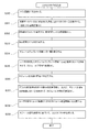
次に、入出力リスト作成装置1によって実行される入出力リスト作成方法を図3〜図6を用いて説明する。図3は、本発明の一実施形態に係る入出力リスト作成方法を示す図である。図4は、本発明の一実施形態に係る入出力リスト作成装置1を示す図である。また、図5A〜図7は、本発明の一実施形態に係る入出力リスト作成装置1によって表示装置16に表示される情報を例示するための図である。図3に示されるように、入出力リスト作成方法は、後述する、候補信号リスト出力ステップ(図3のS32)と、抽出信号リスト生成ステップ(図3のS33)と、信号割付前情報出力ステップ(図3のS35)と、信号割付モジュール情報記憶ステップ(図3のS36)と、装置配置前情報出力ステップ(図3のS37)と、モジュール配置情報記憶ステップ(図3のS38)と、入出力リスト生成ステップ(図3のS39)と、を備える。
Next, the input/output list creation method executed by the input/output
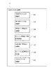
これらのステップの各々は、入出力リスト作成装置1と入出力リスト4を作成する下流工程の設計者(以下、ユーザ)とによってインタラクティブに行われる。すなわち、入出力リスト作成装置1は、ユーザによるマウス14やタッチパネル(表示装置16)などの入出力装置の操作(ユーザの操作)に応じて発生する、上記の各々のステップを実行するための命令を受け付けるステップ(不図示)を経て、各々のステップを実行し、入出力リスト4の作成を支援する。また、入出力リスト作成装置1(入出力リスト作成プログラム)は、例えばソフトウェアで実現される処理機能部を備えており、上記のステップの各々を、それぞれ、候補信号リスト出力処理部42(図3のS32)、抽出信号リスト生成処理部43(図3のS33)、信号割付前情報出力処理部45(図3のS35)、信号割付モジュール情報記憶処理部46(図3のS36)、装置配置前情報出力処理部47(図3のS37)、モジュール配置情報記憶処理部48(図3のS38)、入出力リスト生成処理部49(図3のS39)によって実行する(図4参照)。
Each of these steps is performed interactively by the input/output
また、図3に示される入出力リスト作成方法は、大きく分けて、後述する信号割付モジュール情報を生成するためのステップ(S31〜S36)と、後述するモジュール配置情報を生成するためのステップ(S37〜S38)と、このモジュール配置情報(後述)に基づいて入出力リスト4を生成するためのステップ(S39)とで構成されている。
以下、本発明の一実施形態に係る入出力リスト作成方法を図3のフローに従って説明する。
Furthermore, the input/output list creation method shown in FIG. 3 is broadly composed of steps (S31 to S36) for generating signal allocation module information (described later), steps (S37 to S38) for generating module layout information (described later), and a step (S39) for generating an input/
The input/output list creation method according to an embodiment of the present invention will be described below with reference to the flow chart of FIG.
図3のステップS30において、入出力リスト作成装置1はメイン画面(不図示)を表示する。メイン画面(不図示)は入出力リスト4の作成を開始する起点となる画面である。例えば、マウス14などを操作することで、表示装置16に表示されている特定のアイコンや文字列表示をユーザがクリックなどにより選択することで、上述の入出力リスト作成プログラムが起動し、メイン画面(不図示)が出力される。この出力は、表示装置16に表示され、本実施形態では一例としてディスプレイとしているが、限定されるものでなく、プリンタや別の媒体などでもよい。
In step S30 of FIG. 3, the input/output
図3の次のステップS31において、入出力リスト作成装置1は、支援データベース2に蓄積された過去に作成されたプロジェクト毎の入出力信号を記録した過去入出力リスト3の一覧を表示する。例えば、メイン画面(不図示)に表示された所定のボタン(例えば、過去リスト選択ボタン)をユーザがクリックすると、このユーザの操作によって発する命令を入出力リスト作成装置1は受け付ける(受信する)。そして、この命令を受け付けると、入出力リスト作成装置1は支援データベース2にアクセスし、過去入出力リスト3の各々を識別するための過去リスト識別子81を取得する。また、入出力リスト作成装置1は、この過去リスト識別子81の一覧を表示装置16に出力する。この過去リスト識別子81の一覧は、過去リスト選択画面(不図示)に含められることで、表示装置16に表示されても良い。過去リスト選択画面(不図示)は、過去リスト識別子81の一覧をユーザに提示すると共に、過去入出力リスト3のユーザによる選択(指示)を受け付けるための画面となる。
In the next step S31 in FIG. 3, the input/output
そして、ユーザは、過去リスト選択画面(不図示)に表示された過去リスト識別子81などの情報に基づいて、今回の入出力リスト作成の対象となるプラント制御装置6(上流図面5)と過去入出力リスト3との類似性などを判断し、必要と考えられる1以上の過去入出力リスト3の選択を行う。例えば、表示装置16に表示された過去のプロジェクトで作成した入出力信号が類似している案件の過去リスト識別子81をクリックすることなどにより、ユーザは過去入出力リスト3を選択可能となっている。また、過去リスト選択画面(不図示)に表示された所定のボタン(例えば、信号抽出ボタン)のクリックなどに応じて、入出力リスト作成装置1は、このユーザの操作に対応した命令を受け付け、過去入出力リスト3の選択を確定する。なお、図3〜図6に示される実施形態では、過去リスト識別子81は、過去に行われた設計プロジェクトを表すプロジェクト名称となっている。
Then, the user judges the similarity between the plant control device 6 (upstream drawing 5) for which the current input/output list is to be created and the past input/
図3の次のステップS32において、上述の候補信号リスト出力ステップが実行される。すなわち、入出力リスト作成装置1は、過去に作成された過去入出力リスト3が蓄積された支援データベース2のうちから選択された過去入出力リスト3の信号情報Iを含む候補信号リストL1を表示装置16に出力する。これによって、候補信号リストL1が表示装置16に表示される。具体的には、過去入出力リスト3のユーザによる選択が確定されると、入出力リスト作成装置1は支援データベース2にアクセスし、選択された1以上の過去リスト識別子81の各々に対応する過去入出力リスト3をそれぞれ支援データベース2から読み込む。そして、読み込んだ情報(候補信号リストL1)を表示装置16に出力する。候補信号リストL1は、候補信号リスト選択画面D3(図5A〜図5B参照)に含められることで、表示装置16に表示されても良い。つまり、入出力リスト作成装置1によって候補信号リスト選択画面D3に画面が遷移されることで、候補信号リストL1が表示装置16に表示される。この候補信号リスト選択画面D3は、候補信号リストL1をユーザに提示すると共に、候補信号リストL1に含まれる信号情報Iのユーザによる選択(指示)を受け付けるための画面となる。後述するように、候補信号リスト選択画面D3では、候補信号リストL1に含まれる各々の信号情報Iに対して、ユーザによる選択や非選択を受け付けるためのチェックボックス85が設けられて表示されている(図5A〜図5B参照)。
3, the above-mentioned candidate signal list output step is executed. That is, the input/output
図3の次のステップS33において、上述の抽出信号リスト生成ステップが実行される。すなわち、入出力リスト作成装置1は、候補信号リストL1のうちから選択された過去入出力リスト3の信号情報Iを含む抽出信号リストL2(図6参照)を生成する。具体的には、抽出信号リストL2を生成に先立って、候補信号リストL1の各々の信号情報Iに対応する上述のチェックボックス85がユーザの操作によって選択あるいは非選択されている。そして、所定のボタン(例えば、インポート実行ボタン)のユーザによるクリックなどに応じて、入出力リスト作成装置1は、このユーザの操作に対応した命令を受け付け、候補信号リストL1のうちからの信号情報Iのユーザによる選択を確定する。そして、入出力リスト作成装置1は、チェックボックス85の状態を確認し、選択された信号情報Iを抽出信号リストL2に追加し、非選択された信号情報Iを抽出信号リストL2に追加しないようにすることで、抽出信号リストL2を生成する。また、こうして生成された抽出信号リストL2は、主記憶装置12や補助記憶装置13に記憶される。
In the next step S33 in FIG. 3, the above-mentioned extraction signal list generation step is executed. That is, the input/output
図3の次のステップS34において、入出力リスト作成装置1は、モジュールテンプレート情報Tの一覧を出力する。モジュールテンプレート情報Tは、モジュールMに割付けられる入力信号Siまたは出力信号Soの信号情報IをモジュールM毎に保持するための情報セットである。ユーザが、表示装置16に表示された所定のボタン(例えば、モジュール追加ボタン)をクリックなどすると、入出力リスト作成装置1は、このユーザの操作に対応した命令を受け付け、例えば、ポップアップ画面(不図示)などによりモジュールテンプレート情報Tの一覧を表示する。上述したように、モジュールMは複数種類あるため、各々の種類に対応したモジュールテンプレート情報Tが用意されており、ユーザの操作に応じてこれらの一覧が表示される。そして、ユーザはその中の1つを選択した後に、ポップアップ画面上の所定のボタン(例えば、追加実行ボタン)などをクリックする。これによって、入出力リスト作成装置1は、このユーザの操作に対応した命令を受け付け、モジュールテンプレート情報Tのユーザによる選択を確定し、ポップアップ画面(不図示)を閉じる。
3, the input/output
図3の次のステップS35において、上述の信号割付前情報出力ステップが実行される。すなわち、入出力リスト作成装置1は、ユーザによって選択された、モジュールMに割付けられる入力信号Siまたは出力信号Soの信号情報I(抽出信号リストL2に抽出した信号)をモジュールM毎に保持するためのモジュールテンプレート情報Tおよび抽出信号リストL2を表示装置16に出力する(図6参照)。具体的には、モジュールテンプレート情報Tのユーザによる選択が確定されると、入出力リスト作成装置1は、選択されたモジュールテンプレート情報Tおよび抽出信号リストL2を表示装置16に出力する。例えば、モジュール信号割付画面D4(図6参照)にこれらの情報が含められることで、表示装置16に表示されても良い。つまり、入出力リスト作成装置1によってモジュール信号割付画面D4に画面が遷移されることで、選択されたモジュールテンプレート情報Tおよび抽出信号リストL2が表示装置16に表示される。このモジュール信号割付画面D4は、ユーザによって選択されたモジュールテンプレート情報Tおよび抽出信号リストL2をユーザに提示すると共に、抽出信号リストL2に含まれる信号情報Iとモジュールテンプレート情報Tとの関連付けのユーザ命令を受け付けるための画面となる。
3, the above-mentioned signal pre-allocation information output step is executed. That is, the input/output
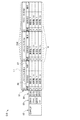
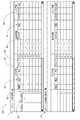
図6は、本発明の一実施形態に係るモジュール信号割付画面D4におけるモジュールテンプレート情報Tおよび抽出信号リストL2の表示態様を示す図である。図6に示される実施形態では、図示されるように、モジュールテンプレート情報Tの一覧からユーザが選択したモジュールテンプレート情報Tと抽出信号リストL2とが並べて表示されている。具体的には、モジュール信号割付画面D4には、それぞれの情報を表示するための領域が設けられている。そして、モジュールテンプレート情報Tはモジュール別信号一覧という見出し(タイトル)と共に、モジュール信号割付画面D4の上方に設けられた領域に表示されている。一方、抽出信号リストL2は、モジュール未割付信号一覧という見出しと共に、モジュールテンプレート情報Tの下方に設けられた領域に表示されている。また、モジュール信号割付画面D4において、モジュールテンプレート情報Tは表形式で表示されており、対応するモジュールMの種類(FXAIM01)と同一種類の中で識別するための情報(FXAIM01−01)を各行のタイトル欄Dt1(見出し欄)として、モジュールMが備えるチャネル部65のチャネル識別子cIdの各々が行方向に並べて表示されている。また、行方向に並べられたチャネル識別子cId(例えば、チャネル番号)の各々に対して、入出力信号Sの信号情報Iが列方向に並べて表示されるようになっている。
6 is a diagram showing the display mode of the module template information T and the extracted signal list L2 on the module signal allocation screen D4 according to one embodiment of the present invention. In the embodiment shown in FIG. 6, as shown in the figure, the module template information T selected by the user from the list of module template information T and the extracted signal list L2 are displayed side by side. Specifically, the module signal allocation screen D4 is provided with an area for displaying each piece of information. The module template information T is displayed in an area provided above the module signal allocation screen D4 together with a heading (title) of a module-specific signal list. On the other hand, the extracted signal list L2 is displayed in an area provided below the module template information T together with a heading of a module unassigned signal list. In addition, in the module signal allocation screen D4, the module template information T is displayed in a table format, and the type of the corresponding module M (FXAIM01) and information (FXAIM01-01) for identifying the same type are displayed as the title column Dt1 (heading column) of each row, and the channel identifiers cId of the
そして、モジュール信号割付画面D4は、このモジュールテンプレート情報Tに含まれる複数のチャネル部65の各々を表すチャネル識別子cIdに対する信号情報Iを格納する欄に対して、抽出信号リストL2の所望として選択した信号情報Iをセットすることが可能となっている。すなわち、下流工程の設計者(ユーザ)は、入出力リスト4の作成にあたって、プラント制御装置6の各々のモジュールMのチャネル部65に対して割付けるべき入出力信号Sを決定するが、まずは、モジュールMが装着されるプラント制御装置6のポート部64の位置とは無関係に、いずれかのポート部64に装着しようとするモジュールMの各々のチャネル部65と割付ける入出力信号Sの信号情報Iとの対応関係を、モジュール信号割付画面D4に表示されるモジュールテンプレート情報Tおよび抽出信号リストL2を用いて作成し、プラント制御装置6に対して信号割付モジュール情報を得ることが可能となっている。
The module signal allocation screen D4 allows the user to set the desired signal information I from the extracted signal list L2 in a field that stores the signal information I for the channel identifier cId representing each of the
図3の次のステップS36において、上述の信号割付モジュール情報記憶ステップが実行される。すなわち、モジュールテンプレート情報Tと、該モジュールテンプレート情報Tに関連付けられた抽出信号リストL2に含まれる過去入出力リスト3の信号情報Iとの対応関係である信号割付モジュール情報L3を記憶する。具体的には、信号割付モジュール情報L3の記憶に先立って、入出力リスト作成装置1は、ユーザによる操作によって行われるモジュールテンプレート情報Tの各々のチャネル識別子cIdと、抽出信号リストL2に含まれる過去入出力リスト3の所望として選択した信号情報Iとの対応づけを受け付ける。そして、ユーザの操作によって作成された信号割付モジュール情報L3を入出力リスト作成装置1は補助記憶装置13などに保存する。
In the next step S36 in FIG. 3, the signal allocation module information storage step described above is executed. That is, signal allocation module information L3, which is a correspondence between the module template information T and the signal information I of the past input/
図3のステップS37において、上述の装置配置前情報出力ステップが実行される。すなわち、入出力リスト作成装置1は、プラント制御装置6のポート部64の配置情報Cおよび信号割付モジュール情報L3を表示装置16に出力する。ポート部64の配置情報Cは、キャビネット部62やサブキャビネット部63に設けられたポート部64の各々を表示する情報であり、配置情報Cから、ポート部64の数や、相対的な位置関係がわかるようになっていても良い。プラント制御装置6においてポート部64は縦横に配置されており(図2参照)、表形式によってポート部64の配置情報Cが表示装置16に表示されても良い。この場合には、表形式に表示されたポート部64の配置情報Cの列方向は、サブキャビネット部63の並びに対応させ、行方向は、ポート部64の並びに対応させても良い。そして、列方向に並べられたサブキャビネット部63の識別子の各々に対して、行方向にポート部64の識別子(ポート識別子pId)が並ぶような表示となる。あるいは、ポート部64の配置情報Cは、図2に例示されるような、プラント制御装置6のキャビネット部62、サブキャビネット部63、ポート部64を図形で表示したものであっても良い。従い、モジュールMに対する信号割付モジュール情報L3が作成にあたり、過去に作成されたプロジュクトの過去入出力リスト3から選択された候補信号リストL1をもとにして、抽出信号リストL2を所望として選択した信号情報Iをセットすることで作成できる。このため拾い出し作業の効率化を図り、手入力作業を排除してスペル間違いなどの入力ミスを防止することが出来る。
3, the above-mentioned pre-device arrangement information output step is executed. That is, the input/output
また、このステップS37は、ユーザによる所定のボタン(例えば、モジュール配置実行ボタン)のクリックなどに応じて、入出力リスト作成装置1は、プラント制御装置6のポート部64の配置情報Cを表示装置16に出力する。また、入出力リスト作成装置1は、例えば、信号割付モジュール情報L3が生成されたモジュールテンプレート情報Tの識別子(図6のFXAIM01−01)を表示することによって、信号割付モジュール情報L3の一覧を表示装置16に表示する。例えば、上記のプラント制御装置6のポート部64の配置情報Cおよび信号割付モジュール情報L3の一覧は、モジュール配置画面D5に含められることで、表示装置16に表示されても良い(図7参照)。このモジュール配置画面D5は、プラント制御装置6のポート部64の配置情報Cおよび信号割付モジュール情報L3をユーザに提示すると共に、プラント制御装置6の所望として選択したポート部64に対する、所望として選択した信号割付モジュール情報L3のユーザの割り当て指示を受け付けるための画面となる。
In step S37, the input/output
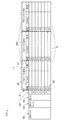
図7は、本発明の一実施形態に係るモジュール配置画面D5に表示されたプラント制御装置6のポート部64の配置情報Cおよび信号割付モジュール情報L3の表示態様を示す図である。図7に示される実施形態のモジュール配置画面D5では、図示されるように、ポート部64の配置情報Cおよび信号割付モジュール情報L3の各々の情報を個別に表示するための領域が画面の左右に設けられている。そして、ポート部64の配置情報Cはキャビネットロケーションという見出し(タイトル)と共に、モジュール配置画面D5の左側に設けられた領域に表示されている。一方、信号割付モジュール情報L3は、割付け可能なモジュールという見出しと共に、ポート部64の配置情報Cが設けられた領域の右側に並べて表示されている。
図7に示される実施形態では、キャビネット部62は、サブキャビネット部63によるコントロールノードを構成しており、モジュール配置画面D5において、ポート部64の配置情報Cは表形式で表示されており、列方向には、プラント制御装置6のキャビネット部62のサブキャビネット部63(Node)が、その前面と背面とに分けて並べられている。具体的には、画面の左に表示されたFRONT(前面)に、Node 1、Node 2、Node 3が列方向に並べられ、その右に表示されたREAR(背面)に、Node 4、Node 5、Node 6が列方向に並べられている。また、行方向にはポート部64が並べられている。一方、信号割付モジュール情報L3は、作成済みの一覧が並べられおり、FXAIM01−01、FXDIM01−01、FXSVL02−01AおよびFXSVL02−01Bが並べられている。
7 is a diagram showing a display mode of the placement information C of the
7, the
なお、上述したように、プラント制御装置6のサブキャビネット部63やポート部64の数など、ハードウェア構成の異なる筐体61が複数用意されている場合には、入出力リスト作成装置1は、ポート部64の配置情報Cの種類の一覧を表示してユーザに選択させると共に、ユーザによる選択結果を受け付けて、ユーザによって選択されたポート部64の配置情報Cをモジュール配置画面D5に表示しても良い。
As described above, when
図3の次のステップS38において、上述のモジュール配置情報記憶ステップが実行される。すなわち、入出力リスト作成装置1は、ユーザの操作によって関連付けされた、信号割付モジュール情報L3とプラント制御装置6のポート部64の配置情報Cとの対応関係であるモジュール配置情報L4を記憶する。具体的には、この対応関係の記憶に先立って、信号割付モジュール情報L3とプラント制御装置6のポート部64の配置情報Cとの対応づけがユーザの操作によりなされており、入出力リスト作成装置1は、ユーザの操作によって作成されたモジュール配置情報L4を補助記憶装置13などに保存する。図7に示される実施形態では、モジュール配置情報L4として、FXAIM01−01、FXDIM01−01、FXSVL02−01AおよびFXSVL02−01Bが既に作成されており、そのうちのFXAIM01−01はユーザの操作によって1CA−1−3と対応づけられる命令がなされることで、この命令を受け付けることで、入出力リスト作成装置1は、1CA−1−3にFXAIM01−01が対応付けられたことを記憶している。
3, the above-mentioned module placement information storage step is executed. That is, the input/output
図3の次のステップS39において、上述の入出力リスト生成ステップが実行される。すなわち、入出力リスト作成装置1は、モジュール配置情報L4に基づいて、入出力リスト4を生成する。例えば、ユーザによる所定のボタン(例えば、作成ボタン)のクリックなどに応じて、入出力リスト作成装置1は、このユーザの操作に対応した命令を受け付け、記憶済みのモジュール配置情報L4の一覧を表示する。そして、この一覧からユーザが所望として選択したモジュール配置情報L4を選択すると、入出力リスト作成装置1はこのユーザの操作を受け付けて、選択されたモジュール配置情報L4に基づいて入出力リスト4を生成する。入出力リスト4には、信号情報Iの全てが含まれても良いし、信号情報Iの一部が含まれても良い。また、生成された入出力リスト4は、補助記憶装置13に記憶されても良いし、表示装置16に出力されることで画面に表示されても良いし、プリンタなどに出力されても良い。従い、プラント制御装置6の各ハードウェア構成と各信号割付モジュール情報との対応づけを信号割付モジュール情報L3の単位で行われる。このため、プラント制御装置6への複数のモジュール配置,追加,削除や、プラント制御装置6における変更が生じた際の修正等も、信号割付モジュール情報L3の単位で修正を行うことが可能であり、入出力リスト4の作成や変更に容易に対応することができる。
In the next step S39 in FIG. 3, the above-mentioned input/output list generation step is executed. That is, the input/output
上記の構成によれば、支援データベース2に蓄積された入力信号Siおよび出力信号Soの信号情報Iを用いて入出力リスト4が作成される。すなわち、入出力リスト4は、上流工程で作成されるプラント制御装置6の基礎となる上流図面5からプラント制御装置6の入出力信号Sを拾い出し、各々の入出力信号Sの信号情報Iを設定することを通して作成されるが、上流図面5から拾い出された入出力信号Sの各々に対して設定すべき信号情報Iを支援データベース2から取得するよう構成することで、信号情報Iの各情報欄の入力および設定作業を軽減でき、入出力リスト4の作成を容易に行うことができる。また、各々の信号情報Iを支援データベース2から取得するので、下流工程において設計者(ユーザ)の手入力作業の排除を図ることができ、入力間違いなどの発生を防止し、プラント制御装置6の設計の効率化を図ることができる。さらに、作成された入出力リスト4に基づいて上流図面5との整合性を確認することができ、整合性確認の容易化を図ることもできる。
According to the above configuration, the input/
また、信号割付モジュール情報L3を作成した後に、モジュール配置情報L4を作成しており、プラント制御装置6のポート部64に対して、支援データベース2から取得した信号情報Iを直接割付けていない。つまり、実際のプラント制御装置6のハードウェア構成と信号割付モジュール情報L3との対応づけは、信号割付モジュール情報L3の単位で行われる。このため、プラント制御装置6が複数のモジュールMを備える場合において、モジュールMの追加、削除や、プラント制御装置6における配置換えなどの変更が生じても、信号割付モジュール情報L3の単位で一括して追加、削除、変更等の修正を行うことが可能であり、これらの変更に容易に対応することができる。
In addition, after creating the signal allocation module information L3, the module arrangement information L4 is created, and the signal information I obtained from the
また、幾つかの実施形態では、信号情報Iは、入力信号Siおよび出力信号Soを識別するためのサービス名86、および、入力信号Siおよび出力信号Soの特性情報87を含んでいる。そして、図5A〜図5Bに示されるように、候補信号リスト出力ステップ(図3のS32)では、過去入出力リスト3毎にサービス名86と特性情報87とが出力される。図5A〜図5Bに示される実施形態では、候補信号リスト選択画面D3には、信号情報Iの有する複数の情報欄のうち、サービス名86(図5A〜図5BのSERVICE)および特性情報87の情報のみが表示されるようになっている。
In some embodiments, the signal information I includes a
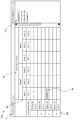
図5Aは、本発明の一実施形態に係る候補信号リスト選択画面D3における候補信号リストL1の表示態様を示す図である。また、図5Bは、図5Aの候補信号リストL1が展開された表示態様を示す図であり、信号情報Iの詳細が示された図である。図5A〜図5Bに示されるように、候補信号リストL1は表形式で表示されている。詳述すると、図5A〜図5Bに示される実施形態では、候補信号リストL1の列方向(左右方向)には、候補信号リストL1の複数の信号情報Iの各々を過去入出力リスト3毎に区分けして表示するためのリスト区分領域Rが並べられている。一方、候補信号リストL1の行方向(上下方向)には、リスト区分領域R毎に、各々の過去入出力リスト3に含まれる信号情報Iが並べられている。また、リスト区分領域Rの各々において表示される信号情報Iの1レコードは、信号情報Iの少なくとも一部の情報と、ユーザによる信号情報Iの選択、非選択の指示を受け付けるためのチェックボックス85とのセットで構成されている。
5A is a diagram showing a display mode of the candidate signal list L1 in the candidate signal list selection screen D3 according to one embodiment of the present invention. FIG. 5B is a diagram showing a display mode in which the candidate signal list L1 in FIG. 5A is expanded, and details of the signal information I are shown. As shown in FIGS. 5A to 5B, the candidate signal list L1 is displayed in a table format. In detail, in the embodiment shown in FIGS. 5A to 5B, list division areas R for dividing and displaying each of the multiple signal information I in the candidate signal list L1 for each past input/
また、各々のリスト区分領域Rの最上部にはリスト区分領域Rの説明を表示するためのタイトル欄Dt2(見出し欄)が設けられている。図5A〜図5Bに示される実施形態では、3つリスト区分領域Rが表示されており、リスト区分領域Rを説明するタイトル欄には、過去リスト識別子81(プロジェクト名称A、プロジェクト名称B、プロジェクト名称C)がそれぞれ表示されている。また、上記のリスト区分領域Rを説明するタイトル欄の1つ下の行には、リスト区分領域Rに含まれる列によって表示される内容を説明するためのタイトル欄が設けられている。図5Bの例示では、列に表示される内容を説明するタイトル欄には、左から、選択との表示により、チェックマークが表示されたチェックボックス85が選択されたものであることを示す説明、および、表示される信号情報Iの各々の情報の内容(SERVICEおよび特性)が表示される。一方、図5Aの例示では、列に表示される内容を説明するタイトル欄には、左から、選択との表示により、選択されたチェックボックス85の選択数(合計数)を示す説明、および、表示される信号情報Iの各々の情報の内容(SERVICEおよび特性)が表示される。
In addition, a title column Dt2 (heading column) for displaying an explanation of the list division region R is provided at the top of each list division region R. In the embodiment shown in Figs. 5A to 5B, three list division regions R are displayed, and the title columns for explaining the list division regions R display past list identifiers 81 (project name A, project name B, project name C), respectively. In addition, a title column for explaining the contents displayed by the columns included in the list division region R is provided in the row below the title column for explaining the list division region R. In the example of Fig. 5B, the title column for explaining the contents displayed in the columns displays, from the left, an explanation indicating that the
また、候補信号リスト選択画面D3に表示される信号情報Iの各々は、入出力信号Sの用途情報82と、入出力信号Sが入力信号Siまたは出力信号Soかを示す信号種別情報83と、モジュールMの種別(種類)を示すモジュール種別情報84と、の3つの情報と共に表示される。このように、3つの情報は表示される全ての信号情報Iの各々に対して表示されるため、候補信号リストL1の行のタイトル欄は全てのリスト区分領域Rの端に配置されている。そして、1つの用途情報82は、その用途を実現するために複数の入出力信号Sが入出力されると共に、複数の入出力信号Sを扱うために複数のモジュールMが用いられるというような関係を有するため、用途情報82が共通する信号情報Iや、用途情報82および信号種別情報83が共通する信号情報Iや、用途情報82および信号種別情報83、モジュール種別情報84が共通する信号情報Iがあるため、共通する部分をまとめて要約表示することや、展開して詳細を表示することが可能になっている。
Each piece of signal information I displayed on the candidate signal list selection screen D3 is displayed with three pieces of information: use
具体的には、図5Aでは、候補信号リストL1は、これらの3つの情報によって信号情報Iが要約表示されている。図5Aでは、用途情報82および信号種別情報83、モジュール種別情報84の3つの情報によって、信号情報Iが要約して表示されており、要約された信号情報Iとして、ユーザによって選択された信号情報Iの数や、モジュールMの各々に含まれる信号情報Iの数が表示されている。
一方、図5Bでは、モジュール種別情報84のチェックマークをクリックすることで、要約表示が展開して表示されており、要約された情報の詳細が表示されている。モジュールMのチャネル部65を示すチャネル識別子cIdの各々に割付けられる信号情報Iの内容が分かるようになっている。また、チェックボックス85も各々の信号情報I毎に表示されており、ユーザによる信号情報Iの選択が可能となっている。なお、表示装置16の画面サイズの関係上、候補信号リストL1に含まれる全てのリスト区分領域Rや、全ての信号情報Iが表示できない場合には、画面の上下方向および左右方向にスクロールバーなどが表示されることで、候補信号リストL1の全ての内容が確認できるようになっている。
Specifically, in Fig. 5A, the candidate signal list L1 displays the signal information I in a summarized form based on these three pieces of information. In Fig. 5A, the signal information I is displayed in a summarized form based on three pieces of information, namely, the
5B, by clicking the check mark of the
上記の構成によれば、候補信号リスト出力ステップS32では、信号情報Iに含まれる様々な情報欄(フィールド)のうち、上流図面5から拾い出された入出力信号Sの各々に対して設定すべき信号情報Iを、候補信号リストL1から選択するのに有益となる信号情報Iのみが画面に表示され、ユーザに提示される。このため、下流工程の設計者(ユーザ)が、プラント制御装置6の知識に基づいて、候補信号リストL1の中から適切な信号情報Iな選択することができる。また、このように、候補信号リストL1で提示する信号情報Iの情報量を小さくすることで、過去入出力リスト3の信号情報を対比可能に並べて提示することができるようになり、候補信号リストL1から該当する信号情報Iの選択をより容易に行うことができる。また、ユーザによる支援データベース2からの信号情報Iの選択が容易となり、プラント制御装置6の入出力信号の拾い出し作業の効率化を図ることができる。
According to the above configuration, in the candidate signal list output step S32, among various information columns (fields) included in the signal information I, only the signal information I that is useful for selecting the signal information I to be set for each of the input/output signals S picked up from the
また、幾つかの実施形態では、上述したように、モジュールテンプレート情報Tは、プラント制御装置6に設置可能な複数のモジュールMの種類毎に設けられると共に、モジュールMの種類に対応した仕様情報をそれぞれ含んでいる。そして、信号割付モジュール情報記憶ステップ(図3のS36)では、仕様情報を満たす信号割付モジュール情報L3を記憶し、仕様情報を満たさない信号割付モジュール情報L3は記憶しないよう構成される。例えば、図6に例示されたモジュールテンプレート情報TはFXAIM01という種類のAIモジュールに対応したものであるが、AIモジュールはアナログ入力を処理するモジュールMであり、処理可能な信号種別88が信号情報Iとして予め格納されている(図6のIO欄)。そして、このAIモジュールはアナログ入力を処理するモジュールMであるため、AIモジュールにアナログ出力(AO)や、デジタル入力(DI)、デジタル出力(DO)となる入出力信号Sは割付けることはできない。このような、割付けることのできない信号情報Iをモジュールテンプレート情報Tに割付けるような操作をユーザが行うと、入出力リスト作成装置1はそのユーザによる割付操作の完了を阻止するなどすることで、主記憶装置12や補助記憶装置13に記憶しないようにする。この際、ユーザの操作が受け付けられない旨やその理由を表示するエラー表示が表示されても良い。その他、仕様情報として、モジュールMの入出力可能な入出力信号Sの数、モジュールMに入出力可能な信号値の上限と下限、モジュールMの冗長構成の対応を示す冗長構成などが含まれても良く、これらの仕様を遵守した入出力信号Sの割り付けを監視し、仕様に当てはまらない割付操作を阻止しても良い。
In some embodiments, as described above, the module template information T is provided for each type of a plurality of modules M that can be installed in the
上記の構成によれば、モジュールテンプレート情報Tには、対応するモジュールMの仕様情報が含まれており、モジュールテンプレート情報Tに割り付けようとする信号情報Iが仕様情報を満たさない場合には、その信号割付モジュール情報の記憶が拒否される。これによって、モジュールMに仕様外の入出力信号Sが割付けられるのを防止することができ、入出力リスト4の作成の効率化を図ることができる。
According to the above configuration, the module template information T includes specification information of the corresponding module M, and if the signal information I to be assigned to the module template information T does not satisfy the specification information, the storage of the signal assignment module information is refused. This makes it possible to prevent an input/output signal S outside the specifications from being assigned to the module M, and makes it possible to create the input/
また、幾つかの実施形態では、ユーザによって予め設定された設定情報に基づいて、ユーザによる誤操作の防止が図られる。例えば、幾つかの実施形態では、ポート部64の配置情報Cには、プラント制御装置6のポート部64に対して装着可能なモジュールMの種類が予め設定されており、モジュール配置情報記憶ステップ(図3のS38)では、ポート部64の配置情報Cにおいて予め設定されたモジュールMの種類と一致するモジュール配置情報L4は記憶し、ポート部64の配置情報Cにおいて予め設定されたモジュールMの種類と一致しないモジュール配置情報L4は記憶しないよう構成される。具体的には、入出力リスト作成装置1は、所定のボタン(例えば、モジュール種類設定ボタン)のクリックなどのユーザの操作に応じて、プラント制御装置6の各々のポート部64に対して、装着可能なモジュールMの種類をユーザが設定するための画面(不図示)を表示装置16に表示する。そして、ユーザは、この画面を介して、ポート部64の配置情報Cに含まれる各々のポート部64の情報に対して装着しようとするモジュールMの種類を指定し、入出力リスト作成装置1は、このユーザによる指定を受け付けてポート部64の配置情報Cの各々のポート部64の情報に対応付けて記憶する。一方、入出力リスト作成装置1は上記のユーザにより設定された情報に基づいて、モジュール配置画面D5におけるユーザの操作を監視する。そして、上述のモジュール配置画面D5に表示されたポート部64の配置情報Cにおいて、モジュールMの種類が指定されたポート部64に、指定されたモジュールMの種類以外の信号割付モジュール情報L3を配置するような操作をユーザが行った場合には、例えば、エラー表示を出力するなどして、そのようなモジュール配置情報L4が主記憶装置12や補助記憶装置13に記憶(生成)されるのを阻止するようにしている。
In some embodiments, the type of the module M that can be attached to the
上記の構成によれば、ポート部64の配置情報Cは、プラント制御装置6が備える複数のポート部64の各々に対応する情報を含んでおり、ポート部64の配置情報Cにおける各々のポート部64の情報に対して設定されたモジュールMの種類と異なるモジュールMの種類を有するモジュール配置情報L4は記憶されないように構成されている。これによって、意図しないモジュール配置情報L4が生成されるのを防止することができ、入出力リスト4の作成の効率化を図ることができる。
According to the above configuration, the
また、幾つかの実施形態では、信号割付モジュール情報L3は、表示装置16に表示されたモジュールテンプレート情報Tの所望として選択した表示部分に、抽出信号リストL2に含まれる信号情報Iがドラッグアンドドロップされることにより、モジュールテンプレート情報Tと抽出信号リストL2の信号情報Iとが対応付けられることで生成される。すなわち、図6に示される実施形態では、ドラッグアンドドロップによって、モジュールテンプレート情報Tの各々の行と、抽出信号リストL2に含まれる信号情報Iとの関連付を行うことが可能となっている。具体的には、ユーザが、マウス14などを用いて、モジュール信号割付画面D4に表示された抽出信号リストL2の上の所望として選択した入出力信号Sを選択すると、入出力リスト作成装置1は、選択された入出力信号Sをハイライトして表示する。また、ユーザが、ハイライトされた信号情報Iをドラッグし、モジュールテンプレート情報Tの所望として選択した行(チャネル部65に対応する行となる上記の表示部分)の上でドロップする。これによって、抽出信号リストL2の信号情報Iが、モジュールテンプレート情報Tのドロップ操作された行で識別されるチャネル部65の信号情報Iに格納され、両者が関連づけられる。
In some embodiments, the signal allocation module information L3 is generated by dragging and dropping the signal information I included in the extracted signal list L2 onto the display portion selected as desired of the module template information T displayed on the
上記の構成によれば、ユーザによるドラッグアンドドロップ操作によって信号割付モジュール情報L3を簡易に作成することができ、入出力リスト4の作成におけるスペル間違えなどの入力ミスを防止することができる。
なお、ハイライトした信号情報Iを割付け操作のための所定のボタン(例えば、割付け操作ボタンなど)を使用してコピーし、モジュールテンプレート情報の所望として選択した行に貼り付けることによる関連づけ操作が可能となっていても良い。
According to the above configuration, the signal allocation module information L3 can be easily created by the user through drag-and-drop operations, and input errors such as spelling mistakes when creating the input/
In addition, it may be possible to perform an association operation by copying the highlighted signal information I using a specified button for allocation operations (e.g., an allocation operation button) and pasting it into the desired selected row of the module template information.
また、幾つかの実施形態では、モジュール配置情報L4は、表示装置16に表示されたプラント制御装置6のポート部64の配置情報Cの所望として選択した表示部分に、信号割付モジュール情報L3がドラッグアンドドロップされることにより、プラント制御装置6のポート部64と信号割付モジュール情報L3とが対応付けられることで生成される。図3〜図6に示される実施形態では、モジュール配置画面D5に表示されるプラント制御装置6のハードウェア構成は、図2に示されるような、コントロールノードを構成しているキャビネット部62、サブキャビネット部63、ポート部64が、筐体61における位置関係が分かるように表形式あるいは図形表示されている。
In some embodiments, the module layout information L4 is generated by dragging and dropping the signal allocation module information L3 onto a desired selected display portion of the layout information C of the
そして、モジュール配置画面D5では、ユーザによるドラッグアンドドロップ操作によって、プラント制御装置6の各々のポート部64と信号割付モジュール情報L3との対応関係を作成することを可能となっている。具体的には、ユーザが、マウス14などを用いて、モジュール配置画面D5に表示された信号割付モジュール情報L3の一覧から所望として選択した信号割付モジュール情報L3を選択すると、入出力リスト作成装置1は、選択された信号割付モジュール情報L3をハイライトして表示する。また、ユーザが、ハイライトされた信号割付モジュール情報L3をドラッグし、表示されたプラント制御装置6の所望として選択したポート部64(表示部分)の上でドロップする。これによって、所望として選択した信号割付モジュール情報L3が、所望として選択したポート部64に対応付けられる。
Then, on the module arrangement screen D5, the user can create a correspondence between each
なお、表示装置16に表示される信号割付モジュール情報L3は、各々の信号割付モジュール情報L3を識別するための識別子(例えば、図6のFXAIM01−01)のみが一覧表示されていても良く、ユーザによる識別子のクリックなどによって、信号割付モジュール情報L3の詳細が別画面で表示されるように構成されても良い。
The signal allocation module information L3 displayed on the
上記の構成によれば、ユーザによるドラッグアンドドロップ操作によってモジュール配置情報L4を簡易に生成することができ、入出力リスト作成における入力ミスを防止することができる。 The above configuration allows the user to easily generate module placement information L4 through drag-and-drop operations, preventing input errors when creating an input/output list.
また、幾つかの実施形態では、過去入出力リスト3の信号情報Iには入出力信号Sの設定値が含まれる。図3〜図6に示される実施形態には、図6に示されるように、信号情報Iは、入出力信号Sの設定値として信号レンジ情報89を含んでいる。図6の例示では、信号レンジ情報89は、図示されるように、入出力信号Sの下限値(図6のLOWER)、上限値(図6のUPPER)、その入出力信号の単位情報(図6のUNIT)で管理されており、過去のプラント制御装置6で用いられた値がセットされている。
In addition, in some embodiments, the signal information I in the past input/
また、入出力信号Sの設定値として、入出力信号Sの信号レンジ情報89をプラント制御装置6の内部でどのように管理するかの情報(測定レンジ情報)を含んでも良い。この測定レンジ情報(不図示)も下限値と上限値と単位の情報で管理されており、その各々が信号レンジ情報89の下限値、上限値、単位に対応する。例えば、信号レンジ情報89の下限値、上限値、単位が、4、20、mA(ミリアンペア)の場合には、測定レンジ情報は、0、100、%などのように対応している。つまり、入出力リスト作成装置1では、4〜20mAという入出力信号Sの信号値は、0〜100%として扱われる。そして、これらの入出力信号Sの設定値は、作成される入出力リスト4に含まれることになる。これによって、過去に使用された実績のある設定値を支援データベース2から取得することができ、プラント制御装置6の各々の信号情報Iの設定の際に、信頼性の高い入出力信号Sの設定値の決定を容易に行うことができる。さらに、信号情報Iは、他の様々な設定値を含んでも良い。
The set values of the input/output signals S may also include information (measurement range information) on how the
また、幾つかの実施形態では、入出力リスト4には、上述した予備率が含まれても良い。モジュールテンプレート情報Tの仕様情報には、モジュールMのチャネル部65の数(チャネル数)および入出力信号Sが割り付けられていないチャネル部65の空き数が含まれており、このチャネル数および空き数から予備率を自動で集計・分析して計算して(予備率=スペア数/チャネル部65の数)、信号情報Iに含めるようにしても良い。なお、モジュールテンプレート情報Tの仕様情報には、チャネル部65の空き数と共に、あるいは、チャネル部65の空き数に代えて、入出力信号Sが割り付けられたチャネル部65の使用数が含まれていても良く、このチャネル数から使用数を減算して空き数を算出するなどすることで、チャネル数および使用数から予備率を自動で計算して、信号情報Iに含めるようにしても良い。
In some embodiments, the input/
本発明は上述した実施形態に限定されることはなく、上述した実施形態に変形を加えた形態や、これらの形態を適宜組み合わせた形態も含む。
例えば、本発明の一実施形態に係る入出力リスト作成装置1の支援により生成された入出力リスト4を支援データベース2に蓄積し、蓄積後に作成される入出力リスト4のために用いられても良い。
The present invention is not limited to the above-described embodiment, and includes modifications to the above-described embodiment and appropriate combinations of these modifications.
For example, the input/
1 入出力リスト作成装置
13 補助記憶装置
14 マウス
15 キーボード
16 表示装置
2 支援データベース
3 過去入出力リスト
4 入出力リスト
42 候補信号リスト出力処理部
43 抽出信号リスト生成処理部
45 信号割付前情報出力処理部
46 信号割付モジュール情報記憶処理部
47 装置配置前情報出力処理部
48 モジュール配置情報記憶処理部
49 入出力リスト生成処理部
5 上流図面
52 システム系統図
6 プラント制御装置(機器システム制御装置)
61 筐体
62 キャビネット部
63 サブキャビネット部
64 ポート部
65 チャネル部
81 過去リスト識別子
82 用途情報
83 信号種別情報
84 モジュール種別情報
85 チェックボックス
86 サービス名
87 特性
88 信号種別
89 信号レンジ情報
L1 候補信号リスト
L2 抽出信号リスト
L3 信号割付モジュール情報
L4 モジュール配置情報
I 信号情報
M モジュール
S 入出力信号
Si 入力信号
So 出力信号
Pi 計装点
Po 操作端
T モジュールテンプレート情報
C ポート部の配置情報
pId ポート識別子
cId チャネル識別子
D3 候補信号リスト選択画面
D4 モジュール信号割付画面
D5 モジュール配置画面
R リスト区分領域
Dt1 タイトル欄
Dt2 タイトル欄
1 Input/Output
61: Housing 62: Cabinet section 63: Sub-cabinet section 64: Port section 65: Channel section 81: Past list identifier 82: Use information 83: Signal type information 84: Module type information 85: Check box 86: Service name 87: Characteristics 88: Signal type 89: Signal range information
L1 Candidate signal list L2 Extracted signal list L3 Signal allocation module information L4 Module layout information I Signal information M Module S Input/output signal Si Input signal So Output signal Pi Instrumentation point Po Control terminal T Module template information C Port layout information pId Port identifier cId Channel identifier
D3 Candidate signal list selection screen D4 Module signal allocation screen D5 Module placement screen R List section area Dt1 Title field Dt2 Title field
Claims (14)
過去に作成された少なくとも1つの過去入出力リストが蓄積された支援データベースのうちから選択された前記過去入出力リストの信号情報を含む候補信号リストを出力する候補信号リスト出力ステップと、
前記候補信号リストのうちから選択された前記過去入出力リストの信号情報を含む抽出信号リストを生成する抽出信号リスト生成ステップと、
前記信号情報を前記モジュール毎に保持するためのモジュールテンプレート情報および前記抽出信号リストを出力する信号割付前情報出力ステップと、
前記モジュールテンプレート情報と、該モジュールテンプレート情報に対して関連付けられた前記抽出信号リストに含まれる前記過去入出力リストの信号情報との対応関係である信号割付モジュール情報を記憶する信号割付モジュール情報記憶ステップと、
前記ポート部の配置情報および前記信号割付モジュール情報を出力する装置配置前情報出力ステップと、
前記信号割付モジュール情報と前記ポート部の配置情報との対応関係であるモジュール配置情報を記憶するモジュール配置情報記憶ステップと、
前記モジュール配置情報に基づいて前記入出力リストを生成する入出力リスト生成ステップと、を備えることを特徴とする入出力リスト作成方法。 1. An input/output list creation method for creating an input/output list including a plurality of pieces of signal information, which are pieces of input signal information or pieces of output signal information assigned to at least one module attached to a port unit of an equipment system control device, comprising:
a candidate signal list output step of outputting a candidate signal list including signal information of a past input/output list selected from a support database in which at least one past input/output list created in the past is stored;
an extracted signal list generating step of generating an extracted signal list including signal information of the past input/output list selected from the candidate signal list;
a signal pre-allocation information output step of outputting module template information for holding the signal information for each module and the extracted signal list;
a signal allocation module information storage step of storing signal allocation module information which is a correspondence relationship between the module template information and the signal information of the past input/output list included in the extracted signal list associated with the module template information;
a pre-device arrangement information output step of outputting the arrangement information of the port unit and the signal allocation module information;
a module layout information storage step of storing module layout information which is a correspondence relationship between the signal allocation module information and layout information of the port unit;
an input/output list generating step of generating the input/output list based on the module layout information.
前記候補信号リスト出力ステップでは、前記過去入出力リスト毎に前記サービス名と前記特性情報とが出力されることを特徴とする請求項1に記載の入出力リスト作成方法。 the signal information includes a service name and characteristic information for identifying the input signal and the output signal;
2. The input/output list creating method according to claim 1, wherein, in said candidate signal list output step, said service name and said characteristic information are output for each of said past input/output lists.
前記信号割付モジュール情報記憶ステップでは、
前記仕様情報を満たす前記信号割付モジュール情報を記憶し、前記仕様情報を満たさない前記信号割付モジュール情報は記憶しないよう構成されることを特徴とする請求項1または2に記載の入出力リスト作成方法。 the module template information includes specification information corresponding to each type of the module,
In the signal allocation module information storage step,
3. The input/output list creating method according to claim 1, further comprising storing the signal allocation module information that satisfies the specification information, and not storing the signal allocation module information that does not satisfy the specification information.
前記モジュール配置情報記憶ステップでは、予め設定された前記モジュールの種類と一致するモジュール配置情報は記憶し、前記モジュールの種類と一致しないモジュール配置情報は記憶しないよう構成されることを特徴とする請求項1〜3のいずれか1項に記載の入出力リスト作成方法。 The type of the module that can be attached to the port unit is set in advance in the arrangement information of the port unit,
4. The input/output list creation method according to claim 1, wherein the module layout information storage step is configured to store module layout information that matches a preset module type, and not to store module layout information that does not match the module type.
過去に作成された少なくとも1つの過去入出力リストが蓄積された支援データベースのうちから選択された前記過去入出力リストの信号情報を含む候補信号リストを出力する候補信号リスト出力処理部と、
前記候補信号リストのうちから選択された前記過去入出力リストの信号情報を含む抽出信号リストを生成する抽出信号リスト生成処理部と、
前記信号情報を前記モジュール毎に保持するためのモジュールテンプレート情報および前記抽出信号リストを出力する信号割付前情報出力処理部と、
前記モジュールテンプレート情報と、該モジュールテンプレート情報に対して関連付けられた前記抽出信号リストに含まれる前記過去入出力リストの信号情報との対応関係である信号割付モジュール情報を記憶する信号割付モジュール情報記憶処理部と、
前記ポート部の配置情報および前記信号割付モジュール情報を出力する装置配置前情報出力処理部と、
前記信号割付モジュール情報と前記ポート部の配置情報との対応関係であるモジュール配置情報を記憶するモジュール配置情報記憶処理部と、
前記モジュール配置情報に基づいて前記入出力リストを生成する入出力リスト生成処理部と、を備えることを特徴とする入出力リスト作成装置。 An input/output list creation device for creating an input/output list including a plurality of pieces of signal information, which are pieces of input signal information or pieces of output signal information assigned to at least one module attached to a port unit of an equipment system control device, comprising:
a candidate signal list output processing unit that outputs a candidate signal list including signal information of a past input/output list selected from a support database in which at least one past input/output list created in the past is stored;
an extracted signal list generation processing unit that generates an extracted signal list including signal information of the past input/output list selected from the candidate signal list;
a signal pre-allocation information output processing unit that outputs module template information for holding the signal information for each of the modules and the extracted signal list;
a signal allocation module information storage processing unit that stores signal allocation module information that is a correspondence relationship between the module template information and signal information of the past input/output list included in the extracted signal list associated with the module template information;
a pre-apparatus arrangement information output processing unit that outputs the port arrangement information and the signal allocation module information;
a module layout information storage processing unit that stores module layout information that is a correspondence relationship between the signal allocation module information and layout information of the port unit;
an input/output list generation processing unit that generates the input/output list based on the module layout information.
前記候補信号リスト出力処理部は、前記過去入出力リスト毎に前記サービス名と前記特性情報とを出力することを特徴とする請求項8に記載の入出力リスト作成装置。 the signal information includes a service name and characteristic information for identifying the input signal and the output signal;
9. The input/output list creation device according to claim 8, wherein the candidate signal list output processing unit outputs the service name and the characteristic information for each of the past input/output lists.
前記信号割付モジュール情報記憶処理部は、
前記仕様情報を満たす前記信号割付モジュール情報を記憶し、前記仕様情報を満たさない前記信号割付モジュール情報は記憶しないよう構成されることを特徴とする請求項8または9に記載の入出力リスト作成装置。 the module template information includes specification information corresponding to each type of the module,
The signal allocation module information storage processing unit includes:
10. The input/output list creation device according to claim 8, configured to store the signal allocation module information that satisfies the specification information, and not store the signal allocation module information that does not satisfy the specification information.
前記モジュール配置情報記憶処理部は、予め設定された前記モジュールの種類と一致するモジュール配置情報は記憶し、前記モジュールの種類と一致しないモジュール配置情報は記憶しないよう構成されることを特徴とする請求項8〜10のいずれか1項に記載の入出力リスト作成装置。 The type of the module that can be attached to the port unit is set in advance in the arrangement information of the port unit,
11. The input/output list creation device according to claim 8, wherein the module placement information storage processing unit is configured to store module placement information that matches a preset module type, and not to store module placement information that does not match the module type.
14. The input/output list creation device according to claim 8, wherein the signal information in the past input/output list includes a setting value of the input signal or the output signal.
Priority Applications (1)
| Application Number | Priority Date | Filing Date | Title |
|---|---|---|---|
| JP2015228716A JP6586355B2 (en) | 2015-11-24 | 2015-11-24 | Input/Output List Creation Method and Input/Output List Creation Device |
Applications Claiming Priority (1)
| Application Number | Priority Date | Filing Date | Title |
|---|---|---|---|
| JP2015228716A JP6586355B2 (en) | 2015-11-24 | 2015-11-24 | Input/Output List Creation Method and Input/Output List Creation Device |
Publications (2)
| Publication Number | Publication Date |
|---|---|
| JP2017097596A JP2017097596A (en) | 2017-06-01 |
| JP6586355B2 true JP6586355B2 (en) | 2019-10-02 |
Family
ID=58816864
Family Applications (1)
| Application Number | Title | Priority Date | Filing Date |
|---|---|---|---|
| JP2015228716A Expired - Fee Related JP6586355B2 (en) | 2015-11-24 | 2015-11-24 | Input/Output List Creation Method and Input/Output List Creation Device |
Country Status (1)
| Country | Link |
|---|---|
| JP (1) | JP6586355B2 (en) |
Families Citing this family (1)
| Publication number | Priority date | Publication date | Assignee | Title |
|---|---|---|---|---|
| CN119520392A (en) * | 2024-11-05 | 2025-02-25 | 广东电网有限责任公司 | Resource allocation method, resource allocation device and storage medium for newly added channels |
-
2015
- 2015-11-24 JP JP2015228716A patent/JP6586355B2/en not_active Expired - Fee Related
Also Published As
| Publication number | Publication date |
|---|---|
| JP2017097596A (en) | 2017-06-01 |
Similar Documents
| Publication | Publication Date | Title |
|---|---|---|
| KR101697031B1 (en) | System building assistance tool and system | |
| JP4490577B2 (en) | PLC system construction support tool | |
| TWI541622B (en) | Apparatus for supporting the compilation of a sequence program | |
| CN101833548B (en) | Input supporting method of variable name in programming of PLC | |
| JP5829780B1 (en) | Programming device | |
| US9959516B2 (en) | Disassembly procedure generating method, apparatus, and system, and replacement procedure generating method, apparatus, and system | |
| JP6529295B2 (en) | System diagram automatic creation system | |
| JP6779418B1 (en) | Design support equipment, design support methods and design support programs | |
| JP5929950B2 (en) | Work plan display system | |
| JP6586355B2 (en) | Input/Output List Creation Method and Input/Output List Creation Device | |
| CN113361064B (en) | Information processing device, information processing method, and computer readable medium | |
| JP2007304660A (en) | Command execution result recording system and command execution result recording method | |
| JP2008197721A (en) | Plant monitoring screen creation device | |
| JP4995009B2 (en) | POD screen generation device and program thereof | |
| JP2012174179A (en) | Operation definition generation device for monitoring control system | |
| CN113361063B (en) | Information processing apparatus, information processing method, and computer readable medium | |
| US20190369820A1 (en) | Supporting device | |
| JP5358317B2 (en) | Energy management device used | |
| US20060101346A1 (en) | Device and method for designing and planning an operating interface | |
| US9769036B1 (en) | Port assignment of network devices reference and management | |
| JP2019149019A (en) | Support system | |
| JP4282961B2 (en) | System that defines data input / output in the controller | |
| JP4588364B2 (en) | Controller screen generator | |
| JP2021060812A (en) | Failure tree generation device and method thereof | |
| JP6144927B2 (en) | Parameter setting apparatus and method |
Legal Events
| Date | Code | Title | Description |
|---|---|---|---|
| A625 | Written request for application examination (by other person) |
Free format text: JAPANESE INTERMEDIATE CODE: A625 Effective date: 20181016 |
|
| A977 | Report on retrieval |
Free format text: JAPANESE INTERMEDIATE CODE: A971007 Effective date: 20190807 |
|
| TRDD | Decision of grant or rejection written | ||
| A01 | Written decision to grant a patent or to grant a registration (utility model) |
Free format text: JAPANESE INTERMEDIATE CODE: A01 Effective date: 20190813 |
|
| A61 | First payment of annual fees (during grant procedure) |
Free format text: JAPANESE INTERMEDIATE CODE: A61 Effective date: 20190909 |
|
| R150 | Certificate of patent or registration of utility model |
Ref document number: 6586355 Country of ref document: JP Free format text: JAPANESE INTERMEDIATE CODE: R150 |
|
| S533 | Written request for registration of change of name |
Free format text: JAPANESE INTERMEDIATE CODE: R313533 |
|
| R350 | Written notification of registration of transfer |
Free format text: JAPANESE INTERMEDIATE CODE: R350 |
|
| LAPS | Cancellation because of no payment of annual fees |