JP5358317B2 - Energy management device used - Google Patents
Energy management device used Download PDFInfo
- Publication number
- JP5358317B2 JP5358317B2 JP2009151838A JP2009151838A JP5358317B2 JP 5358317 B2 JP5358317 B2 JP 5358317B2 JP 2009151838 A JP2009151838 A JP 2009151838A JP 2009151838 A JP2009151838 A JP 2009151838A JP 5358317 B2 JP5358317 B2 JP 5358317B2
- Authority
- JP
- Japan
- Prior art keywords
- energy
- time zone
- value
- power demand
- power
- Prior art date
- Legal status (The legal status is an assumption and is not a legal conclusion. Google has not performed a legal analysis and makes no representation as to the accuracy of the status listed.)
- Expired - Fee Related
Links
Images

Classifications
-
- Y—GENERAL TAGGING OF NEW TECHNOLOGICAL DEVELOPMENTS; GENERAL TAGGING OF CROSS-SECTIONAL TECHNOLOGIES SPANNING OVER SEVERAL SECTIONS OF THE IPC; TECHNICAL SUBJECTS COVERED BY FORMER USPC CROSS-REFERENCE ART COLLECTIONS [XRACs] AND DIGESTS
- Y04—INFORMATION OR COMMUNICATION TECHNOLOGIES HAVING AN IMPACT ON OTHER TECHNOLOGY AREAS
- Y04S—SYSTEMS INTEGRATING TECHNOLOGIES RELATED TO POWER NETWORK OPERATION, COMMUNICATION OR INFORMATION TECHNOLOGIES FOR IMPROVING THE ELECTRICAL POWER GENERATION, TRANSMISSION, DISTRIBUTION, MANAGEMENT OR USAGE, i.e. SMART GRIDS
- Y04S10/00—Systems supporting electrical power generation, transmission or distribution
- Y04S10/50—Systems or methods supporting the power network operation or management, involving a certain degree of interaction with the load-side end user applications
Landscapes
- Supply And Distribution Of Alternating Current (AREA)
- Management, Administration, Business Operations System, And Electronic Commerce (AREA)
Description
この発明は、電力会社との契約電力の管理運用の際に、効率的な電力デマンド監視を計画する場合などに特に好ましく用いることができる使用エネルギー管理装置に関する。 The present invention relates to a use energy management apparatus that can be particularly preferably used in the case of planning efficient power demand monitoring when managing contract power with an electric power company.
従来の使用エネルギー管理装置である電力デマンド監視装置として、監視対象装置の電力量を取り込んで現在電力量、デマンド監視終了時点での予測電力を演算し、この予測電力が予め設定された電力デマンド値を超過しているか否かを判定し、電力デマンド値の超過が予測されるとその度合いに応じて複数段の警報レベルを出力する機能、これらのデータを保存する機能及びこれらのデータを表示データとして送信可能な表示機能、ネットワークへの接続機能を備えた電力デマンド監視装置がある(例えば特許文献1参照)。なお、電力デマンド監視とは、電力デマンド値(一定時間内での平均電力)を常時監視し、設定値(例:契約電力の90%等)を超過する恐れがある場合に警報を出力し、設定値の超過を防止するためのものである。 As a power demand monitoring device that is a conventional energy management device used, the power amount of the monitoring target device is taken in, the current power amount and the predicted power at the end of demand monitoring are calculated, and this predicted power is a preset power demand value A function to output multiple levels of alarms according to the degree of the power demand value being predicted, a function to store these data, and display these data as display data There is a power demand monitoring device provided with a display function that can be transmitted as a network and a network connection function (see, for example, Patent Document 1). In addition, power demand monitoring always monitors the power demand value (average power within a certain period of time) and outputs an alarm when there is a risk of exceeding a set value (eg, 90% of contract power) This is to prevent the setting value from being exceeded.
上記のような電力デマンド監視装置は、一般的にコンピュータプログラムからなるソフトウェアを含む監視装置と電力デマンド計測装置からなる。監視装置は、電力デマンド監視部と契約電力などを保存する記憶部などを有するコンピュータ装置からなる。契約電力の値は予め決定され、記憶部に記録されている必要があり、電力デマンド監視部は、記憶部に記録された契約電力値と電力デマンド計測装置から出力される電力デマンド計測値に基づいて、電力デマンド監視を行う。特許文献1に記載された技術は通信ネットワークを利用して電力デマンド監視を効率よく実施するようにしたものであるが、従来の電力デマンド監視装置では、契約電力に対する計画値は別途手段にて計画し、予め決定しておく必要があった。また、過去の電力デマンドの実績データを参考にして計画する場合、別途手段にて実績データの保存・表示を行う必要があり、特に時間帯別に契約電力を計画する場合、多大な労力を要するという課題があった。
The power demand monitoring apparatus as described above generally includes a monitoring apparatus including software including a computer program and a power demand measuring apparatus. The monitoring device includes a computer device having a power demand monitoring unit and a storage unit that stores contract power and the like. The value of the contract power needs to be determined in advance and recorded in the storage unit. The power demand monitoring unit is based on the contract power value recorded in the storage unit and the power demand measurement value output from the power demand measurement device. Power demand monitoring. The technique described in
この発明は上記のような従来技術の実情に鑑みなされたもので、将来の使用エネルギーの計画値設定が容易で、作業性が向上された使用エネルギー管理装置を提供することを目的としている。 The present invention has been made in view of the above-described prior art, and an object of the present invention is to provide a use energy management device in which a planned value of future use energy can be easily set and workability is improved.
この発明に係る使用エネルギー管理装置は、情報の記憶手段と、表示手段と、将来の使用エネルギーの計画値設定手段とを備え、上記記憶手段に記憶された過去の使用エネルギーの実績情報を上記表示手段に表示しているときに、上記計画値設定手段により将来の使用エネルギーの計画値を時間帯別に設定するようにしたものである。 The energy use management apparatus according to the present invention comprises information storage means, display means, and plan value setting means for future energy use, and displays the past use energy performance information stored in the memory means. When displayed on the means, the planned value setting means sets the planned value of future energy use for each time zone.
この発明においては、過去の使用エネルギーの実績情報を表示手段に表示しているときに、将来の使用エネルギーの計画値を時間帯別に設定するようにしたので、将来の使用エネルギーの計画値を過去の実績データと視覚的に比較しながら設定できる。このため、計画値設定が容易で、正確かつ効率的に行うことができる。また、時間帯毎での計画も容易となる。 In the present invention, when the past information on the past used energy is displayed on the display means, the planned value of the future used energy is set for each time zone. It can be set while visually comparing with actual data. For this reason, plan value setting is easy and can be performed accurately and efficiently. In addition, planning for each time zone becomes easy.
実施の形態1.
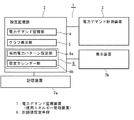
以下、図1〜図5を参照して本発明の実施の形態1による使用エネルギー管理装置である電力デマンド監視装置について説明する。図1において、電力デマンド監視装置1は、記憶手段であるハードディスク、フラッシュメモリなどの記憶装置7a、表示手段である液晶ディスプレイなどの表示装置7b、及び何れも図示省略している中央処理装置、各種入出力インターフェイス、並びにキーボード、及びマウス等のポインティングデバイスを含む入力装置を備えたコンピュータ装置と、このコンピュータ装置を動作させる電力デマンド監視ソフトウェアを有する設定・監視部2と、電力デマンド計測装置3からなる。上記設定・監視部2は、電力デマンド監視部4、グラフ表示部5、並びに契約電力パターン設定部6a、及び設定カレンダー部6bからなる計画値設定手段6を備えている。なお、電力デマンド計測装置3は例えば従来技術による一般的な計測手段などを特別な制限なく用いることができる。
Hereinafter, a power demand monitoring apparatus that is an energy use management apparatus according to
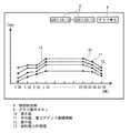
上記グラフ表示部5は、記憶装置7aに記憶された過去の電力デマンドなど使用エネルギーの実績情報や設定された契約電力パターンなどをグラフ表示する。表示装置7bに表示される図2に例示する画面上部における、過去の電力デマンド実績値の表示期間を指定するための期間指定部8に、ユーザからデータが入力され、グラフ表示ボタン9がマウス等でクリックされると、電力デマンド実績値の最大値10と、平均値11と、最小値12からなる統計情報が時間帯別の折れ線グラフとして表示される。
The
なお、後述するステップで、将来の契約電力の時間帯別の計画値(契約電力パターン)が入力されると、その契約電力計画値13が同一座標軸上に時間帯別の折れ線グラフとして追加表示される。なお、表示期間を指定する際には、期間指定部8をマウス等でクリックすることで、日付のキーボード入力が可能となる。なお、年と月を指定したときに当該年月のカレンダーを表示させ、表示されたカレンダー上の所望の日にち(範囲)をマウス等でクリックすることで、表示期間を指定するようにしても良い。
In addition, when a planned value (contract power pattern) of future contract power for each time zone is input in a step described later, the contract
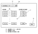
一方、上記契約電力パターン設定部6aの機能を動作させるときには、図3に例示される画面により行われる。なお、図2、図3の画面、及び後述する図4の画面は、好ましくは例えば1つの大きな表示装置7bに同時に並べて表示され、あるいは並置された複数の小さな表示装置7bに同時に表示される。図3において、契約電力パターン表示部14は、契約電力パターン毎に付与された契約電力パターンの名称を表示し、新規に設定し、あるいは変更するためのものである。ボタン14aをマウス等でクリックすることで、例えばデフォルトで設定された複数の契約電力パターン名が一覧表示され、あるいは過去に設定された契約電力パターンがある場合には、それを含む契約電力パターン名が一覧表示され、その中から任意のものを選択可能である。
On the other hand, when the function of the contract power
また、キーボード入力により、契約電力パターンの名称を変更し、あるいは新たな契約電力パターン名を設定することも可能に構成されている。また、契約電力の時間帯入力部15には、任意の該当部分をマウス等でクリックすることで時間帯のキーボード入力が可能である。また、時間帯毎に契約電力の計画値を設定するための契約電力計画値入力部16は、任意の該当部分をマウス等でクリックすることでキーボード入力が可能である。なお、契約電力計画値入力部16の右隣りには契約電力の単位17が図の例では「kw」のように表示される。上記契約電力パターン表示部14、時間帯入力部15、及び契約電力計画値入力部16の各欄に所望の設定入力を行った後、保存ボタン18をマウス等でクリックすることで、設定された各データが記憶装置7aに保存される。
Further, it is possible to change the name of the contract power pattern or set a new contract power pattern name by keyboard input. In addition, a time zone keyboard can be input to the contract power time
また、上記設定カレンダー部6bにおいては、図4に例示する画面に基づいて設定が行われる。図4において、画面上部には表示する年月を選択するための年月選択ボックス19が配設されており、マウス等でボタン19a、または19bをクリックすることで、年、または月を選択可能である。なお、例えば国民の祝日、振替休日、ユーザ企業等の独自の休日などを別途データファイルとして記憶装置7aに保存しておき、年月選択ボックス19でカレンダーを呼び出したときに、それらの休日を例えば赤色文字で表示し、あるいは休日を稼働日にしている場合に該当日にマークを付すなどの機能を付加するように構成しても差し支えない。さらに、画面右上方側には、図3で設定された契約電力パターンの表示部が配設され、契約電力パターン名称20とその契約電力パターンに対応する契約電力パターン番号21がシリーズ番号順に一覧表示される。
In the
そして、画面中央部から左側の主スペースには年月選択ボックス19で指定された年月のカレンダー22が表示され、表示された各日付の直下部に、当該日の契約電力パターン番号21から選ばれた番号をそれぞれ設定入力するように構成されている。なお、契約電力パターン番号を設定するには、契約電力パターン番号21の中から設定しようとする所定の番号をマウス等でクリックした後、所望の日付をマウス等で順次クリックすることで、直前にクリックした契約電力パターン番号21に設定することができる。上記のように所要データを設定した後、保存ボタン23をマウス等でクリックすることで、設定カレンダー22で設定された内容が記憶装置7aに保存される。
In the main space on the left side from the center of the screen, a
一方、上記電力デマンド監視部4では、上記のように構成されたプログラムで設定された契約電力パターンの計画値を用いて電力デマンド監視が行われる。なお、電力デマンド監視部4のシステム構成、監視方式、制御方式等は従来技術による例えば公知のものを適宜選択して用いることができる部分であるので、ここでは説明を省略する。
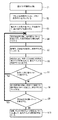
次に上記のように構成された実施の形態1の動作について、図5のフロー図を参照して同図中に示すステップS1〜S10の順に説明する。なお、図2、図3、及び図4の画面を起動するためのボタン類は、設定監視部2が起動されたときの図示省略している初期画面に設けられている。
On the other hand, the power
Next, the operation of the first embodiment configured as described above will be described in the order of steps S1 to S10 shown in FIG. 5 with reference to the flowchart of FIG. The buttons for activating the screens of FIGS. 2, 3, and 4 are provided on an initial screen (not shown) when the
S1.図2の画面を起動する。
S2.図2の期間指定部8をマウス等でクリックし、過去、例えば前年または前々年等過年度同時期の電力デマンド実績値の表示期間を指定した後、グラフ表示ボタン9をクリックする。
S3.図2のように、画面上にステップS2で指定された期間に対応する過去の電力デマンド実績値の最大値10、平均値11、最小値12が折れ線グラフとして表示される。
S4.図3の画面を起動し、ボタン14aをクリックして契約電力パターン表示部14に新規に登録し、または更新しようとする契約電力パターン名を選択する。名称の変更が必要な場合、更新入力を行う。
S5.続いて、図2に表示された過去の電力デマンド実績値の情報を参照しながら、時間帯入力部15、及び契約電力計画値入力部16に所望のデータを入力して、時間帯別の計画値を入力した後、保存ボタン18をクリックする。
S1. The screen of FIG. 2 is activated.
S2. 2 is clicked with a mouse or the like to specify the display period of the power demand actual value in the past, for example, the same period of the previous year such as the previous year or the previous year, and then the
S3. As shown in FIG. 2, the
S4. The screen of FIG. 3 is activated, and the
S5. Next, while referring to the past power demand actual value information displayed in FIG. 2, the desired data is input to the time
S6.図2の画面にステップS4、S5で設定された契約電力計画値が追加表示されるので、過去の電力デマンド実績値の最大値10、平均値11、最小値12と比較して、確認する。
S7.ステップS6における比較、確認の結果、修正を必要とする場合はステップS4に戻り、修正を必要としない場合は次のステップS8に進む。なお、修正するときは、図3の画面で時間帯入力部15と契約電力計画値入力部16を再入力し、保存ボタン18をクリックする。
S8.図4の画面を起動する。そして、将来の具体的な日にち毎にそれぞれ計画した所望の契約電力パターンのパターン番号を設定し、保存ボタン23をクリックして設定内容を保存する。
S9.ステップS8において保存した内容に変更が必要な場合、ステップS4に戻り、保存された内容を必要に応じて変更する。
S10.電力デマンド監視部4において、電力デマンド監視を行うときは、電力デマンド計測装置3から入力される電力デマンド計測値と、計画値設定手段6で設定された契約電力パターンの計画値に基づき、電力デマンド監視が実行される。
S6. Since the contract power plan value set in steps S4 and S5 is additionally displayed on the screen of FIG. 2, comparison is made with the
S7. As a result of the comparison and confirmation in step S6, if correction is required, the process returns to step S4. If correction is not required, the process proceeds to the next step S8. When the correction is made, the time
S8. The screen of FIG. 4 is activated. Then, the pattern number of the desired contract power pattern planned for each specific date in the future is set, and the
S9. When the content stored in step S8 needs to be changed, the process returns to step S4, and the stored content is changed as necessary.
S10. When the power
上記のように、実施の形態1においては、計画値設定手段6によって、過去の実績値の統計情報を図2のようにグラフとして視覚的に表示しながら、将来の契約電力の時間帯毎の計画値を設定することができる。また、設定した契約電力の時間帯毎の計画値を過去の実績値のグラフに追加し、過去の実績情報と比較することができるなどの支援機能を有する。また、設定した計画契約電力の時間帯毎の計画値は、契約電力パターンとして保存される。また、電力デマンド監視部4により、計画値設定手段6によって設定保存された契約電力パターンの計画値に基づいて、従来の監視装置と同様に電力デマンドの監視を実行するものである。
As described above, in the first embodiment, the plan value setting means 6 visually displays the past actual value statistical information as a graph as shown in FIG. Plan values can be set. Moreover, it has a support function such as adding the planned value of the set contract power for each time zone to the past actual value graph and comparing it with the past actual information. In addition, the planned value of the set planned contract power for each time zone is stored as a contract power pattern. The power
上記のように、実施の形態1によれば、過去の使用エネルギーの実績情報を表示装置7bに表示しているときに、将来の使用エネルギーの計画値を時間帯別に設定し得るようにしたので、ユーザは将来の使用エネルギーの計画値を過去の実績データと視覚的に比較しながら設定できる。このため、計画値設定が容易で、正確かつ効率的に行うことができる。また、時間帯毎での計画も容易となる。また、設定した契約電力の計画値を契約電力パターンとして保存し、そのまま電力デマンド監視部4において将来の電力デマンドの監視に使用できるため、業務を効率化できるなどの効果が得られる。さらに、設定の効率化により、省エネにつなげることもできる。
As described above, according to the first embodiment, when the past use energy record information is displayed on the
なお、上記実施の形態の説明では、エネルギーが電力の場合について説明したが、電力に限定されるものではなく、例えばガス、石油類など、他のエネルギーの管理にも同様に適用することができる。また、使用エネルギー管理装置の構成、画面のレイアウト、図5のフロー図に例示された操作や動作の手順など、この発明の範囲内で種々の変更や変形が可能であることは言うまでもない。 In the description of the above embodiment, the case where energy is electric power has been described. However, the present invention is not limited to electric power, and can be similarly applied to management of other energy such as gas and petroleum. . In addition, it goes without saying that various changes and modifications can be made within the scope of the present invention, such as the configuration of the energy management apparatus, the layout of the screen, and the operation and operation procedure illustrated in the flowchart of FIG.
1 電力デマンド監視装置、 2 設定・監視部、 3 電力デマンド計測装置、 4 電力デマンド監視部、 5 グラフ表示部、 6 計画値設定手段、 6a 契約電力パターン設定部、 6b 設定カレンダー部、 7a 記憶装置、 7b 表示装置、 8 期間指定部、 9 グラフ表示ボタン、 10 最大値、 11 平均値、 12 最小値、 13 契約電力計画値、 14 契約電力パターン表示部、 14a ボタン、 15 時間帯入力部、 16 契約電力計画値入力部、 17 契約電力の単位、 18 保存ボタン、 19 年月選択ボックス、 19a、19b ボタン、 20 契約電力パターンの名称、 21 契約電力パターン番号、 22 カレンダー、 23 保存ボタン。
DESCRIPTION OF
Claims (5)
Priority Applications (1)
| Application Number | Priority Date | Filing Date | Title |
|---|---|---|---|
| JP2009151838A JP5358317B2 (en) | 2009-06-26 | 2009-06-26 | Energy management device used |
Applications Claiming Priority (1)
| Application Number | Priority Date | Filing Date | Title |
|---|---|---|---|
| JP2009151838A JP5358317B2 (en) | 2009-06-26 | 2009-06-26 | Energy management device used |
Publications (2)
| Publication Number | Publication Date |
|---|---|
| JP2011010470A JP2011010470A (en) | 2011-01-13 |
| JP5358317B2 true JP5358317B2 (en) | 2013-12-04 |
Family
ID=43566453
Family Applications (1)
| Application Number | Title | Priority Date | Filing Date |
|---|---|---|---|
| JP2009151838A Expired - Fee Related JP5358317B2 (en) | 2009-06-26 | 2009-06-26 | Energy management device used |
Country Status (1)
| Country | Link |
|---|---|
| JP (1) | JP5358317B2 (en) |
Families Citing this family (3)
| Publication number | Priority date | Publication date | Assignee | Title |
|---|---|---|---|---|
| JP5746964B2 (en) * | 2011-12-27 | 2015-07-08 | 株式会社富士通ソーシアルサイエンスラボラトリ | Power management system used |
| WO2013132581A1 (en) * | 2012-03-05 | 2013-09-12 | パイオニア株式会社 | Measurement device, measurement method, measurement program and recording medium capable of recording measurement program |
| JP7728152B2 (en) * | 2021-11-09 | 2025-08-22 | ヤンマーホールディングス株式会社 | display device |
Family Cites Families (2)
| Publication number | Priority date | Publication date | Assignee | Title |
|---|---|---|---|---|
| JP3839440B2 (en) * | 2004-03-10 | 2006-11-01 | 株式会社エヌ・ティ・ティ・データ | Energy management device, facility monitoring control device, energy management program, and facility monitoring control program |
| JP2006349483A (en) * | 2005-06-15 | 2006-12-28 | Cosmo Life Kk | Electric power consumption monitoring system |
-
2009
- 2009-06-26 JP JP2009151838A patent/JP5358317B2/en not_active Expired - Fee Related
Also Published As
| Publication number | Publication date |
|---|---|
| JP2011010470A (en) | 2011-01-13 |
Similar Documents
| Publication | Publication Date | Title |
|---|---|---|
| WO2007130180A1 (en) | Visual workflow process notation and layout | |
| CN102841787A (en) | Chart generation device and chart generation method | |
| JP6121068B2 (en) | Information system construction support tool and information system construction support program | |
| JP2009169882A (en) | Data management apparatus, data management method, and data management program | |
| JP5358317B2 (en) | Energy management device used | |
| JP2009157690A (en) | Manufacturing process management apparatus, manufacturing process management method, program and recording medium for the same | |
| JP5205286B2 (en) | Parts ordering support apparatus and method | |
| KR101431995B1 (en) | Facility management device, screen display method, and recording medium | |
| JP6626327B2 (en) | Gantt chart generation program, Gantt chart generation device, and Gantt chart generation method | |
| TWI472889B (en) | Plc design device | |
| JP2012208900A (en) | Progress display device, progress display method, and progress display program | |
| WO2019187087A1 (en) | Picture drawing device, picture drawing program, and storage medium | |
| JP4875646B2 (en) | Plant monitoring device | |
| JP2020095328A (en) | Equipment monitoring device and graph display method | |
| US20110029350A1 (en) | Method and system for calendaring events | |
| JP5780387B2 (en) | Field data display device | |
| JP2019079086A (en) | Personnel management system | |
| JP2018106581A (en) | Business improvement support system | |
| JP6886841B2 (en) | Design support device | |
| JP4479778B2 (en) | Information management program and information management apparatus | |
| JP6389947B1 (en) | Information processing system, information processing apparatus, and program | |
| JP2018128919A (en) | Work plan creation system, work plan creation method and work plan creation program | |
| JP6586355B2 (en) | Input/Output List Creation Method and Input/Output List Creation Device | |
| JP7692845B2 (en) | Information processing device and information processing method | |
| JP2013125424A (en) | Symbol generating device for graphic screen |
Legal Events
| Date | Code | Title | Description |
|---|---|---|---|
| A621 | Written request for application examination |
Free format text: JAPANESE INTERMEDIATE CODE: A621 Effective date: 20120615 |
|
| TRDD | Decision of grant or rejection written | ||
| A01 | Written decision to grant a patent or to grant a registration (utility model) |
Free format text: JAPANESE INTERMEDIATE CODE: A01 Effective date: 20130820 |
|
| A61 | First payment of annual fees (during grant procedure) |
Free format text: JAPANESE INTERMEDIATE CODE: A61 Effective date: 20130902 |
|
| R150 | Certificate of patent or registration of utility model |
Ref document number: 5358317 Country of ref document: JP Free format text: JAPANESE INTERMEDIATE CODE: R150 Free format text: JAPANESE INTERMEDIATE CODE: R150 |
|
| R250 | Receipt of annual fees |
Free format text: JAPANESE INTERMEDIATE CODE: R250 |
|
| R250 | Receipt of annual fees |
Free format text: JAPANESE INTERMEDIATE CODE: R250 |
|
| R250 | Receipt of annual fees |
Free format text: JAPANESE INTERMEDIATE CODE: R250 |
|
| R250 | Receipt of annual fees |
Free format text: JAPANESE INTERMEDIATE CODE: R250 |
|
| R250 | Receipt of annual fees |
Free format text: JAPANESE INTERMEDIATE CODE: R250 |
|
| R250 | Receipt of annual fees |
Free format text: JAPANESE INTERMEDIATE CODE: R250 |
|
| R250 | Receipt of annual fees |
Free format text: JAPANESE INTERMEDIATE CODE: R250 |
|
| LAPS | Cancellation because of no payment of annual fees |