JP6584473B2 - Fuel pump and method of winding stator core winding of fuel pump - Google Patents

Fuel pump and method of winding stator core winding of fuel pump Download PDF

Info

Publication number
JP6584473B2
JP6584473B2 JP2017206825A JP2017206825A JP6584473B2 JP 6584473 B2 JP6584473 B2 JP 6584473B2 JP 2017206825 A JP2017206825 A JP 2017206825A JP 2017206825 A JP2017206825 A JP 2017206825A JP 6584473 B2 JP6584473 B2 JP 6584473B2
Authority
JP
Japan
Prior art keywords
stator core
winding
neutral point
fuel pump
bobbin
Prior art date
Legal status (The legal status is an assumption and is not a legal conclusion. Google has not performed a legal analysis and makes no representation as to the accuracy of the status listed.)
Expired - Fee Related
Application number
JP2017206825A
Other languages
Japanese (ja)
Other versions
JP2019080445A (en
Inventor
泰士 山本
泰士 山本
啓生 大藤
啓生 大藤
一之 山本
一之 山本
Current Assignee (The listed assignees may be inaccurate. Google has not performed a legal analysis and makes no representation or warranty as to the accuracy of the list.)
Mitsubishi Electric Corp
Original Assignee
Mitsubishi Electric Corp
Priority date (The priority date is an assumption and is not a legal conclusion. Google has not performed a legal analysis and makes no representation as to the accuracy of the date listed.)
Filing date
Publication date
Application filed by Mitsubishi Electric Corp filed Critical Mitsubishi Electric Corp
Priority to JP2017206825A priority Critical patent/JP6584473B2/en
Publication of JP2019080445A publication Critical patent/JP2019080445A/en
Application granted granted Critical
Publication of JP6584473B2 publication Critical patent/JP6584473B2/en
Expired - Fee Related legal-status Critical Current
Anticipated expiration legal-status Critical

Links

Images

Description

本発明は、燃料タンクから燃料を吸い上げて、エンジン等の機器に供給するモータを備えた燃料ポンプに関する発明である。   The present invention relates to a fuel pump including a motor that sucks fuel from a fuel tank and supplies the fuel to equipment such as an engine.

燃料ポンプの駆動源として、ブラシレスモータを用いた例を特許文献1に示す。
特許文献1のブラシレスモータでは、複数の巻線のカバーエンド側の端部同士は、1つのターミナルサブアッシーによって結線されている。即ち、ターミナル部をカバーエンド側で連結し、ターミナルサブアッシーとすることで、モータの巻線端部の取り回し、及び結線を容易にしている。
特許文献2のモータでは、ターミナル挿入部をステータコア内周側に設置し、巻線とターミナルのヒュージング用穴をターミナル上端部に設け、ターミナルと巻線の接合作業性を向上する。巻線とターミナルをヒュージング用の穴にヒュージングした後に、ヒュージング用の穴が設けられたターミナル上部をコア内周側に折り曲げることで、ターミナル部のモータ軸方向長さを短くしている。
Patent Document 1 shows an example in which a brushless motor is used as a drive source of a fuel pump.
In the brushless motor of Patent Document 1, ends on the cover end side of a plurality of windings are connected by a single terminal sub-assembly. That is, by connecting the terminal portion on the cover end side to form a terminal sub-assembly, the winding end of the motor can be easily routed and connected.
In the motor of Patent Document 2, the terminal insertion portion is installed on the inner peripheral side of the stator core, and the fusing holes of the winding and the terminal are provided in the upper end portion of the terminal, thereby improving the workability of joining the terminal and the winding. After fusing the winding and terminal into the fusing hole, the length of the terminal in the motor axis direction is shortened by bending the upper part of the terminal with the fusing hole to the inner periphery of the core. .

特開2012−228178号公報JP 2012-228178 A 特開平11−150904号公報JP-A-11-150904

特許文献1では、ターミナルサブアッシーは軸方向のカバーエンド側に設けられるため、ターミナル部のモータ軸方向長さが長くなり、それにより、モータ全長が長くなってしまう。
特許文献2ではコイル接続用端子部がステータコアのコイルよりも内周側に設置されているため、連結板部をコア内周方向外方側に折り曲げた際に、折れ曲ったターミナルがモータ径方向に長くなってしまい、モータ全体が径方向に大きくなってしまう。
この発明は、上記のような課題を解決するためになされたものであり、電源供給ターミナル、及び、中性点ターミナルのモータ軸方向長さとモータ径方向長さの縮小を図ることを目的とする。
In Patent Document 1, since the terminal sub-assembly is provided on the cover end side in the axial direction, the length of the terminal portion in the motor axial direction is increased, thereby increasing the total length of the motor.
In Patent Document 2, since the coil connection terminal portion is installed on the inner peripheral side with respect to the coil of the stator core, when the connecting plate portion is bent outward in the core inner peripheral direction, the bent terminal becomes the motor radial direction. And the entire motor becomes larger in the radial direction.
The present invention has been made to solve the above-described problems, and aims to reduce the length in the motor axial direction and the length in the motor radial direction of the power supply terminal and the neutral point terminal. .

この発明に係る燃料ポンプは、
回転子部とステータコア部からなるモータ、回転子部の回転により、燃料吸入口より燃料を吸い込み、ステータコア部と回転子部の間を通過した後、エンドカバー部の吐出口より吐出するものであって、ステータコア部は、円環状のステータコア、ステータコアに装着されたボビン、ボビンに巻回されている巻線、ボビンに装着され、巻線に電気的に接続されている中性点ターミナルからなり、中性点ターミナルは、ステータコアの内周と外周の間で、ステータコアの径方向内側に伸び、ステータコアの径方向内側に伸びた部分に巻線からげ部を有し、この巻線からげ部は、ボビンに巻回されている巻線の上方に配置されていることを特徴とする。
The fuel pump according to the present invention is:
A motor composed of a rotor part and a stator core part, and the rotation of the rotor part, sucks fuel from the fuel suction port, passes through between the stator core part and the rotor part, and then discharges it from the discharge port of the end cover part. Te, stator core portion, an annular stator core, a bobbin mounted on the stator core, winding is wound around a bobbin is mounted on a bobbin, it consists neutral point terminal is electrically connected to the winding, The neutral point terminal extends between the inner periphery and the outer periphery of the stator core and extends radially inward of the stator core, and has a winding curl at a portion extending radially inward of the stator core. It is arranged above the winding wound around the bobbin .

この発明の燃料ポンプによれば、モータが軸方向、径方向に縮小でき、小型化を図れる。   According to the fuel pump of the present invention, the motor can be reduced in the axial direction and the radial direction, and the size can be reduced.

本発明の実施の形態1にかかる燃料ポンプの断面図である。It is sectional drawing of the fuel pump concerning Embodiment 1 of this invention. 本発明の実施の形態1にかかる燃料ポンプの上面図である。It is a top view of the fuel pump concerning Embodiment 1 of the present invention. 図1のAA断面図である。It is AA sectional drawing of FIG. 本発明の実施の形態1にかかる燃料ポンプのステータコア部の断面図で、電源供給ターミナルと中性点ターミナルの折り曲げ工程図である。It is sectional drawing of the stator core part of the fuel pump concerning Embodiment 1 of this invention, and is a bending process figure of a power supply terminal and a neutral point terminal. 本発明の実施の形態1にかかる燃料ポンプのステータコア部の電源供給ターミナルと中性点ターミナルの折り曲げ後の上面図である。It is a top view after the power supply terminal and neutral point terminal of the stator core part of the fuel pump concerning Embodiment 1 of the present invention are bent. 本発明の実施の形態1と比較するための参考用燃料ポンプの断面図である。It is sectional drawing of the fuel pump for a reference for comparing with Embodiment 1 of this invention. 本発明の実施の形態1と比較するための参考用燃料ポンプの上面図である。It is a top view of the fuel pump for reference for comparing with Embodiment 1 of the present invention. 本発明の実施の形態2にかかる燃料ポンプの断面図である。It is sectional drawing of the fuel pump concerning Embodiment 2 of this invention. 本発明の実施の形態2にかかる燃料ポンプのステータコア部の構成を示す上面図である。It is a top view which shows the structure of the stator core part of the fuel pump concerning Embodiment 2 of this invention. 本発明の実施の形態2と比較するための参考用燃料ポンプのボビンへの巻線工程説明図とステータコア部の断面図である。It is a winding process explanatory drawing to the bobbin of the fuel pump for a reference for comparing with Embodiment 2 of the present invention, and a sectional view of a stator core part. 本発明の実施の形態2にかかる燃料ポンプのボビンへの巻線工程説明図とステータコア部の断面図である。It is winding process explanatory drawing to the bobbin of the fuel pump concerning Embodiment 2 of this invention, and sectional drawing of a stator core part. 本発明の実施の形態2にかかる燃料ポンプのステータコア部の断面図で、中性点ターミナルの折り曲げ工程図である。It is sectional drawing of the stator core part of the fuel pump concerning Embodiment 2 of this invention, and is a bending process figure of a neutral point terminal. 本発明の実施の形態3にかかる燃料ポンプの断面図である。It is sectional drawing of the fuel pump concerning Embodiment 3 of this invention. 本発明の実施の形態3にかかる燃料ポンプのステータコア部の断面図で、電源供給ターミナルと中性点ターミナルの折り曲げ工程図である。It is sectional drawing of the stator core part of the fuel pump concerning Embodiment 3 of this invention, and is a bending process figure of a power supply terminal and a neutral point terminal. 本発明の実施の形態3にかかる燃料ポンプのステータコア部の電源供給ターミナルと中性点ターミナルの折り曲げ前後の上面図である。It is a top view before and behind the bending of the power supply terminal and neutral point terminal of the stator core part of the fuel pump concerning Embodiment 3 of this invention. 本発明の実施の形態3にかかる燃料ポンプの中性点ターミナルの正面図である。It is a front view of the neutral point terminal of the fuel pump concerning Embodiment 3 of this invention.

実施の形態1.
図1は、本発明の実施の形態1の燃料ポンプの断面図である。図2は、図1の上面図を、図3は、図1のAA断面図を示す。燃料ポンプ10は、自動車等の燃料タンク内に設置されるインタンク式の燃料ポンプである。図1において、燃料を送り出すポンプ部20と、ポンプ部20を駆動させるモータ部30とから構成される。
Embodiment 1 FIG.
FIG. 1 is a cross-sectional view of a fuel pump according to Embodiment 1 of the present invention. 2 is a top view of FIG. 1, and FIG. 3 is a cross-sectional view along AA of FIG. The fuel pump 10 is an in-tank type fuel pump installed in a fuel tank of an automobile or the like. In FIG. 1, it is comprised from the pump part 20 which sends out fuel, and the motor part 30 which drives the pump part 20. In FIG.

図1に示す通り、ポンプ部20はポンプケース21、22とインペラ23とから構成される。すなわち、ポンプケース21は円筒状の金属ハウジング71の内周側に圧入されて固定されており、その内周部にインペラ23を挿入した後、インペラ23を収納するようにポンプケース21と外周を合わせるようにポンプケース22を被せ、金属ハウジング71の一端をかしめてポンプケース22を固定している。このような構成により、外周を合わせて固定されたポンプケース21、22には、インペラ23を収容する空間部25が形成され、この空間部25と連通する燃料吸入口24がポンプケース22に形成され、燃料吐出口26がポンプケース21に形成されている。   As shown in FIG. 1, the pump unit 20 includes pump cases 21 and 22 and an impeller 23. That is, the pump case 21 is press-fitted and fixed to the inner peripheral side of the cylindrical metal housing 71. After the impeller 23 is inserted into the inner peripheral portion, the pump case 21 and the outer periphery are placed so as to accommodate the impeller 23. The pump case 22 is covered so as to match, and one end of the metal housing 71 is caulked to fix the pump case 22. With such a configuration, the pump case 21, 22 fixed with the outer periphery is formed with a space portion 25 for accommodating the impeller 23, and a fuel inlet 24 communicating with the space portion 25 is formed in the pump case 22. The fuel discharge port 26 is formed in the pump case 21.

モータ部30は、ステータコア部40と回転子部70からなる。回転子部70は、永久磁石51とシャフト52とが樹脂部材53で固定され、ステータコア部40の内周側に設置されている。インペラ23はシャフト52の切欠き部54で連結されており、シャフト52を回転軸とした回転子部70の回転に追従するように構成されている。   The motor unit 30 includes a stator core unit 40 and a rotor unit 70. In the rotor part 70, the permanent magnet 51 and the shaft 52 are fixed by the resin member 53, and the rotor part 70 is installed on the inner peripheral side of the stator core part 40. The impeller 23 is connected by a notch portion 54 of the shaft 52 and is configured to follow the rotation of the rotor portion 70 with the shaft 52 as a rotation axis.

ステータコア部40のステータコア44は、電磁鋼板をモータ軸方向(シャフト52の長手方向)にかしめながら積層されて形成されており、図3に示す通り、モータ部30の内周方向に6個のティース45が円周方向に等間隔に形成されている。各々のティース45には、ボビン41が装着され、ボビン41上にコイル(巻線)42が巻回されている。   The stator core 44 of the stator core portion 40 is formed by laminating electromagnetic steel plates while being caulked in the motor axial direction (longitudinal direction of the shaft 52). As shown in FIG. 3, six teeth are arranged in the inner peripheral direction of the motor portion 30. 45 are formed at equal intervals in the circumferential direction. A bobbin 41 is attached to each tooth 45, and a coil (winding) 42 is wound on the bobbin 41.

各々のティース45に巻回されたコイル42は、電源供給ターミナル81と中性点ターミナル82に電気的に接続されており、回転子部70の位置に応じて通電が制御されている。電源供給ターミナル81と中性点ターミナル82のそれぞれに、巻線からげ部84、85が設けられ、図1に示す通り、これら巻線からげ部84,85は、ステータコア44の径方向内側に向いて配置されている。これにより、電源供給ターミナル81、及び中性点ターミナル82もステータコア44の径方向内側に折り曲げられている。   The coils 42 wound around the teeth 45 are electrically connected to the power supply terminal 81 and the neutral point terminal 82, and energization is controlled according to the position of the rotor portion 70. Each of the power supply terminal 81 and the neutral point terminal 82 is provided with winding curled portions 84, 85. As shown in FIG. 1, these winding curled portions 84, 85 are arranged on the radially inner side of the stator core 44. It is arranged facing. Thereby, the power supply terminal 81 and the neutral point terminal 82 are also bent inward in the radial direction of the stator core 44.

エンドカバー部60は、ステータコア部40と、回転子部70のシャフト52の軸受け61と、金属ハウジング71を絶縁樹脂部材でモールド一体成形して製作される。その後、金属ハウジング71のモータ軸方向の吐出口側端部72をステータコア部40の内周側に折り曲げるカーリング加工を行うことで、エンドカバー部60がモータ軸方向に固定されている。   The end cover portion 60 is manufactured by integrally molding the stator core portion 40, the bearing 61 of the shaft 52 of the rotor portion 70, and the metal housing 71 with an insulating resin member. Thereafter, the end cover portion 60 is fixed in the motor axial direction by performing curling processing in which the discharge port side end portion 72 in the motor axial direction of the metal housing 71 is bent toward the inner peripheral side of the stator core portion 40.

このように構成された燃料ポンプ10は、電源供給ターミナル81に、制御された電流を通電することにより、回転子部70を回転させ、シャフト52に連結されたインペラ23が追従して回転することによりポンプケース22の燃料吸入口24より燃料を吸い込み、空間部25を経由し、ポンプケース22の燃料吐出口26から金属ハウジング71の内部に送り出され、ステータコア部40の内周と回転子部70の隙間を通過した後、エンドカバー部60の吐出口62から燃料を吐出する。   The fuel pump 10 configured as described above causes the rotor 70 to rotate by supplying a controlled current to the power supply terminal 81, and the impeller 23 connected to the shaft 52 follows and rotates. Then, the fuel is sucked from the fuel inlet 24 of the pump case 22 and sent out from the fuel outlet 26 of the pump case 22 to the inside of the metal housing 71 through the space 25, and the inner periphery of the stator core portion 40 and the rotor portion 70. After passing through the gap, the fuel is discharged from the discharge port 62 of the end cover portion 60.

次に、電源供給ターミナル81、及び中性点ターミナル82が、ステータコア44の内径方向に折り曲げられ、ステータコア部40が図1の形状に変形する工程を説明する。図4は、本発明の実施の形態1にかかるステータコア部40の変形工程図を示し、図5に変形後のステータコア部40の上面図を示す。
まず、ステータコア部40は、巻線を巻き終わった後、巻線と電源供給ターミナル81の巻線からげ部84とを、ヒュージング等で電気的に連結する。同様に、巻線と中性点ターミナル82の巻線からげ部85とを、ヒュージング等で電気的に連結する。
次に、図4(a)に示すように、電源供給ターミナル81のうち、巻線からげ部84より上部を、ステータコア44の径方向外側であるP方向へ折り曲げる。その後、図4(b)に示すように、電源供給ターミナル81の、巻線からげ部84より下部を、ステータコア44の径方向内側であるQ方向へ折り曲げる。
また、図4(b)に示すように、中性点ターミナル82は巻線からげ部85より下部をステータコア44の径方向内側であるS方向へ折り曲げる。
Next, a process in which the power supply terminal 81 and the neutral point terminal 82 are bent in the inner diameter direction of the stator core 44 and the stator core portion 40 is deformed into the shape of FIG. 1 will be described. FIG. 4 shows a deformation process diagram of the stator core portion 40 according to the first embodiment of the present invention, and FIG. 5 shows a top view of the stator core portion 40 after the deformation.
First, after the winding of the stator core 40 is completed, the winding and the winding portion 84 of the power supply terminal 81 are electrically connected by fusing or the like. Similarly, the winding and the winding-up part 85 of the neutral point terminal 82 are electrically connected by fusing or the like.
Next, as shown in FIG. 4A, the upper portion of the power supply terminal 81 from the winding curled portion 84 is bent in the P direction which is the radially outer side of the stator core 44. Thereafter, as shown in FIG. 4B, the lower portion of the power supply terminal 81 than the winding curled portion 84 is bent in the Q direction which is the radially inner side of the stator core 44.
Further, as shown in FIG. 4B, the neutral point terminal 82 bends the lower part from the winding curled portion 85 in the S direction which is the radially inner side of the stator core 44.

図1との比較のため、電源供給ターミナル81と中性点ターミナル82を変形させずに、エンドカバー部60をモールド成形した場合の燃料ポンプの断面図を図6に示す。また、図6の燃料ポンプの上面図を図7に示す。図1に示された本発明の実施の形態1にかかる燃料ポンプは図6の燃料ポンプと比較し、以下のような効果が認められる。   For comparison with FIG. 1, FIG. 6 shows a cross-sectional view of the fuel pump when the end cover portion 60 is molded without deforming the power supply terminal 81 and the neutral point terminal 82. FIG. 7 shows a top view of the fuel pump of FIG. The fuel pump according to the first embodiment of the present invention shown in FIG. 1 has the following effects compared with the fuel pump of FIG.

(効果1)
図1の燃料ポンプ10は電源供給ターミナル81、中性点ターミナル82がステータコア44の径方向内側に向いて配置されていることにより、電源供給ターミナル81に取付けられた巻線からげ部84、及び中性点ターミナルに取付けられた巻線からげ部85のモータ軸方向長さが短くなる。これにより、ステータコア部40を覆っているエンドカバー部60もモータ部30の回転軸方向長さを短くすることができるため、モータ部30の全長を短くすることができる。
(Effect 1)
The fuel pump 10 of FIG. 1 has a power supply terminal 81, a neutral point terminal 82 arranged radially inward of the stator core 44, so that a winding curl 84 attached to the power supply terminal 81, and The length in the motor axial direction of the winding portion 85 attached to the neutral point terminal is shortened. Thereby, since the end cover part 60 which covers the stator core part 40 can also shorten the rotating shaft direction length of the motor part 30, the full length of the motor part 30 can be shortened.

(効果2)
図6または図7では電源供給ターミナル81と、金属ハウジング71の吐出口側端部72との距離が近く、絶縁距離Hを十分に確保できていないのに対し、図1の燃料ポンプ10では電源供給ターミナル81がステータコア44の径方向内側に折り曲げられているため、絶縁距離Hを十分に確保することができる。同様に、中性点ターミナル82と金属ハウジング71の絶縁距離も十分に確保することができる。
(Effect 2)
6 or 7, the distance between the power supply terminal 81 and the discharge port side end 72 of the metal housing 71 is short, and the insulation distance H is not sufficiently secured, whereas the fuel pump 10 of FIG. Since the supply terminal 81 is bent inward in the radial direction of the stator core 44, the insulation distance H can be sufficiently secured. Similarly, a sufficient insulation distance between the neutral point terminal 82 and the metal housing 71 can be secured.

(効果3)
さらに、図7に対し、図2では、電源供給ターミナル81のエンドカバー部60から突き出している部分83がモータ部30の径方向内周側に配置され、吐出口62近い位置にあるため、吐出口62と電源供給ターミナル81を、図示しない燃料供給装置ユニットへ連結する際に、燃料供給装置ユニットとの連結部を小さくすることができ、図示しない燃料供給装置ユニットとの連結部を燃料供給装置ユニット内に配置できる箇所の自由度が高くなるため、レイアウト性が向上する。
(Effect 3)
Furthermore, in contrast to FIG. 7, in FIG. 2, the portion 83 protruding from the end cover portion 60 of the power supply terminal 81 is disposed on the radially inner peripheral side of the motor portion 30 and is located near the discharge port 62. When connecting the outlet 62 and the power supply terminal 81 to a fuel supply device unit (not shown), the connection portion with the fuel supply device unit can be reduced, and the connection portion with the fuel supply device unit (not shown) is connected to the fuel supply device. Since the degree of freedom of the places that can be arranged in the unit is increased, the layout is improved.

(効果4)
図5に示すように、電源供給ターミナル81と、中性点ターミナル82はステータコア44の径方向において、ステータコア44の外周面より内側に、ステータコア44の内周面よりも外側に収まっているため、端子によって、エンドカバー部60の外周が大きくなることがなく、エンドカバー部60の内周が小さくなることがない。
(Effect 4)
As shown in FIG. 5, the power supply terminal 81 and the neutral point terminal 82 are located inside the outer peripheral surface of the stator core 44 and outside the inner peripheral surface of the stator core 44 in the radial direction of the stator core 44. The terminal does not increase the outer periphery of the end cover portion 60, and the inner periphery of the end cover portion 60 does not decrease.

実施の形態2.
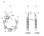
本発明の実施の形態2にかかる燃料ポンプは、中性点ターミナル82の形状が実施の形態1の燃料ポンプと異なる。図8に本発明の実施の形態2にかかる燃料ポンプの断面図を示す。この燃料ポンプでは、ステータコアに装着されたボビン上に、高密度に巻線を巻くため、フライヤ巻線方式にて、巻線を巻くことを想定している。巻線作業の工程を以下に説明する。
図9(a)にステータコア44を、図9(b)にステータコア44に、ボビン41、電源供給ターミナル81、中性点ターミナル82を装着した図を、図10(a)にステータコア44にフライヤ巻線機101にて、巻線を巻いている図を示す。
Embodiment 2. FIG.
The fuel pump according to the second embodiment of the present invention is different from the fuel pump according to the first embodiment in the shape of the neutral point terminal 82. FIG. 8 is a sectional view of a fuel pump according to the second embodiment of the present invention. In this fuel pump, it is assumed that the winding is wound by the flyer winding method in order to wind the winding with high density on the bobbin attached to the stator core. The winding work process will be described below.
9A shows the stator core 44, FIG. 9B shows the stator core 44 with the bobbin 41, the power supply terminal 81, and the neutral point terminal 82. FIG. 10A shows the stator core 44 with flyer winding. The figure which has wound the winding in the wire machine 101 is shown.

図9(a)のステータコア44は、巻線を巻くティース45を所有している磁極片50と、ティース45が無い継鉄片46が交互に配置されており、それらの連結部47によって折り曲げ可能に連結されている。ステータコア44の両端部は連結部が無く、一方は凸形状48、もう一方は凹形状49を設けて、互いに付き合わされている。絶縁樹脂部材であるボビン(例えば41a、41b)に電源供給ターミナル81と中性点ターミナル82を装着し、その後、ステータコア44にボビンを装着した状態を図9(b)に示している。   In the stator core 44 of FIG. 9A, the pole pieces 50 having the teeth 45 wound with the windings and the yoke pieces 46 without the teeth 45 are alternately arranged, and can be bent by the connecting portions 47. It is connected. The both ends of the stator core 44 have no connection part, one is provided with a convex shape 48, and the other is provided with a concave shape 49, and they are attached to each other. FIG. 9B shows a state where the power supply terminal 81 and the neutral point terminal 82 are mounted on bobbins (for example, 41a and 41b) which are insulating resin members, and then the bobbin is mounted on the stator core 44.

図10は、本発明の実施の形態2と比較するための参考用燃料ポンプのボビンへの巻線工程説明図とステータコア部の断面図である。図10(a)は、フライヤ巻線機での巻線動作説明図である。ステータコア44は図9(b)の形状から、フライヤ巻線機101のフライヤ部102が隣接する磁極片に当たらない角度になるよう、各連結部47をステータコア44の外周側へ折り曲げている状態であり、ステータコア44の端部の磁極片50aに装着された電源供給ターミナル81に巻線をからげ、巻線が巻線からげ部84からはずれないように、電源供給ターミナル81の巻線からげ部84をかしめ、ボビン41aへ巻線を巻きつけている途中の状態を示している。   FIG. 10 is an explanatory diagram of a winding process to a bobbin of a reference fuel pump and a sectional view of a stator core part for comparison with Embodiment 2 of the present invention. FIG. 10A is an explanatory diagram of a winding operation in a flyer winding machine. The stator core 44 is in a state in which each connecting portion 47 is bent to the outer peripheral side of the stator core 44 so that the flyer portion 102 of the flyer winding machine 101 does not hit an adjacent magnetic pole piece from the shape of FIG. The winding is wound around the power supply terminal 81 attached to the magnetic pole piece 50a at the end of the stator core 44, and the winding of the power supply terminal 81 is prevented so that the winding does not come off from the winding flange 84. The part 84 is caulked and the winding is wound around the bobbin 41a.

図10(b)に図10(a)のBB断面図を、図10(c)に図10(a)のCC断面図を示す。電源供給ターミナル81の巻線からげ部84は、ボビン41aに巻線を巻きつける際に巻線が通過する、ボビンのモータ軸方向上部領域103に入らないようにステータコア44の外周方向に倒されている。これにより、巻線と電源供給ターミナルの巻線からげ部84が干渉することなく、フライヤ部102にて巻線作業可能となっている。磁極片50aのボビン41aへ巻線を巻いた後は、巻線をステータコア44の背面を渡り、磁極片50bのボビンへ巻線を巻き、磁極片50bのボビンに巻線を巻きつけた後に、中性点ターミナルの巻線からげ部85へ巻線をかけ、巻線からげ部85をステータコア外周側へ倒す手順となる。そのため、磁極片50bのボビンに巻線を巻く際は、中性点ターミナルの巻線からげ部85は図10(c)のように、ボビンに巻線を巻きつける際に巻線が通過するボビンのモータ軸方向上部領域103に侵入してしまう状態となり、フライヤ部102による巻線動作が不可能となる。このため、図11(a)、(b)に示すように中性点ターミナル86を装着することで、モータ軸方向上部領域103を確保し、フライヤ巻線機101にて巻線を行う。   FIG. 10B shows a BB sectional view of FIG. 10A, and FIG. 10C shows a CC sectional view of FIG. The winding curled portion 84 of the power supply terminal 81 is tilted in the outer peripheral direction of the stator core 44 so as not to enter the upper region 103 in the motor axial direction of the bobbin through which the winding passes when the winding is wound around the bobbin 41a. ing. As a result, the flyer 102 can perform the winding work without interference between the winding and the bald portion 84 of the power supply terminal. After winding the winding around the bobbin 41a of the pole piece 50a, the winding is wound around the back surface of the stator core 44, wound around the bobbin of the pole piece 50b, and wound around the bobbin of the pole piece 50b. The winding is applied from the winding of the neutral point terminal to the bald portion 85, and the winding bald portion 85 is tilted toward the outer periphery of the stator core. Therefore, when winding the winding around the bobbin of the magnetic pole piece 50b, the winding hook 85 of the neutral point terminal passes through the winding when winding the winding around the bobbin as shown in FIG. The bobbin enters the upper region 103 in the motor axial direction, and the winding operation by the flyer unit 102 becomes impossible. For this reason, as shown in FIGS. 11A and 11B, the neutral point terminal 86 is attached to secure the motor axial direction upper region 103 and the flyer winding machine 101 performs winding.

すなわち、図11(b)に示すように、中性点ターミナル86はボビンに巻線を巻きつける際に巻線が通過するボビン41bのモータ軸方向上部領域103に巻線からげ部87が侵入しないように、ステータコア背面方向に端子を折り曲げたクランク形状(S字形状を含む)となっている。これにより、フライヤ部102での巻線作業が可能となる。図12に中性点ターミナル86の折り曲げ工程を説明した図を示す。図11(b)に示したように、ステータコア背面方向に端子を折り曲げることにより、フライヤ部102での巻線が可能になったが、端子の巻線からげ部87がステータコアの外周よりも外側へはみ出してしまっているため、エンドカバーの外径が大きくなり、モータの外径が大きくなってしまう。従って、巻線動作後、図12のようにステータコアの内周側T方向へ中性点ターミナル86を折り曲げることで、端子の巻線からげ部87がステータコアの外周よりも外側へのはみ出しを回避することができる。   That is, as shown in FIG. 11 (b), the neutral point terminal 86 enters the upper portion 103 of the bobbin 41b in the motor axial direction of the bobbin 41b through which the winding passes when the winding is wound around the bobbin. In order to avoid this, a crank shape (including an S-shape) is formed by bending the terminal in the direction of the back surface of the stator core. Thereby, the winding work in the flyer part 102 becomes possible. FIG. 12 is a view for explaining the bending process of the neutral point terminal 86. FIG. As shown in FIG. 11 (b), the winding at the flyer portion 102 is made possible by bending the terminal toward the back surface of the stator core, but the winding portion 87 of the terminal is outside the outer periphery of the stator core. Since it protrudes, the outer diameter of an end cover will become large and the outer diameter of a motor will become large. Therefore, after the winding operation, the neutral point terminal 86 is bent in the T direction on the inner peripheral side of the stator core as shown in FIG. 12, thereby avoiding the protruding portion 87 of the terminal winding bulge outward from the outer periphery of the stator core. can do.

(効果)
以上より、ボビンへの巻線作業でフライヤを用いて高密度で巻線を巻くために中性点ターミナル86の巻線からげ部87をボビンに巻線を巻きつける際に巻線が通過するボビンのモータ軸方向上部領域103からはずれるように、巻線からげ部をステータコア外周側へ逃がし、その後、中性点ターミナル86をステータコア44の内周側へ折り曲げることで、径方向の拡大を回避することができる。
(effect)
From the above, the winding passes when winding the winding portion 87 of the neutral point terminal 86 around the bobbin in order to wind the winding at a high density using the flyer in the winding operation to the bobbin. To avoid the enlargement in the radial direction, the winding bald part is released to the outer periphery side of the stator core so as to be separated from the upper axial region 103 of the bobbin, and then the neutral point terminal 86 is bent to the inner periphery side of the stator core 44. can do.

実施の形態3.
本発明の実施の形態3にかかる燃料ポンプは、中性点ターミナル82の形状が実施の形態1で説明したものと異なる。図13に実施の形態3による燃料ポンプを示す。図14に実施の形態3による燃料ポンプの中性点ターミナル88の折り曲げ工程図を示し、図15(a)に中性点ターミナル88の折り曲げ前のステータコア部上面図を、図15(b)に中性点ターミナル88の折り曲げ後のステータコア部上面図を示す。図16(a)にステータコアの磁極片50cに装着されている中性点ターミナル88cを、図15(a)のステータコア内周のE方向から見た正面図を示す。図16(b)にステータコアの磁極片50dに装着されている中性点ターミナル88dをステータコア内周のF方向から見た正面図を示す。図16bにステータコアの磁極片50eに装着されている中性点ターミナル88eをステータコア内周のG方向から見た正面図を示す。
Embodiment 3 FIG.
In the fuel pump according to the third embodiment of the present invention, the shape of the neutral point terminal 82 is different from that described in the first embodiment. FIG. 13 shows a fuel pump according to the third embodiment. FIG. 14 shows a bending process diagram of the neutral point terminal 88 of the fuel pump according to the third embodiment. FIG. 15A shows a top view of the stator core portion before the neutral point terminal 88 is bent, and FIG. The stator core part top view after the neutral point terminal 88 is bent is shown. FIG. 16A is a front view of the neutral point terminal 88c mounted on the magnetic pole piece 50c of the stator core as viewed from the E direction on the inner periphery of the stator core in FIG. FIG. 16B shows a front view of the neutral point terminal 88d mounted on the magnetic pole piece 50d of the stator core as seen from the F direction on the inner periphery of the stator core. FIG. 16b shows a front view of the neutral point terminal 88e attached to the magnetic pole piece 50e of the stator core as seen from the G direction on the inner periphery of the stator core.

このように、磁極片50c、50d、50eにそれぞれ異なる形状の中性点ターミナル88c、88d、88eを装着している。中性点ターミナル88cは、図13及び図16のz軸方向で、磁極片50cのティース45に直交する方向に伸び、その先端に、磁極片50d側に伸びた中性点連結部91を有している。中性点ターミナル88dは、中性点ターミナル88cと同方向に伸び、その先端に、磁極片50c側に伸びた中性点連結部92と、磁極片50e側に伸びた中性点連結部93を有している。中性点ターミナル88eは、中性点ターミナル88c、88dと同方向に伸び、その先端に、磁極片50d側に伸びた中性点連結部94有している。図14に示すように、中性点ターミナル88(88c、88d、88c)をステータコア44の内周側へ折り曲げる際、図15(b)に示す通り、中性点ターミナル88c、88eを先に曲げておき、その後、中性点ターミナル88cを曲げることで、中性点ターミナル88cの中性点連結部91のz軸方向上部に中性点ターミナル88dの中性点連結部92が、中性点ターミナル88eの中性点連結部94のz軸方向上部に中性点ターミナル88dの中性点連結部93が接触する。それぞれの接触部をはんだ付けやプロジェクション溶接等で溶接することで、中性点の連結が可能となる。図14に示す電源供給ターミナル81の折り曲げは、実施の形態1で説明したのと同様であるため省略する。   In this manner, the neutral point terminals 88c, 88d, and 88e having different shapes are attached to the magnetic pole pieces 50c, 50d, and 50e, respectively. The neutral point terminal 88c extends in a direction perpendicular to the teeth 45 of the magnetic pole piece 50c in the z-axis direction of FIGS. 13 and 16, and has a neutral point connecting portion 91 extending toward the magnetic pole piece 50d at its tip. is doing. The neutral point terminal 88d extends in the same direction as the neutral point terminal 88c, and at its tip, a neutral point connection portion 92 extending toward the magnetic pole piece 50c and a neutral point connection portion 93 extending toward the magnetic pole piece 50e. have. The neutral point terminal 88e extends in the same direction as the neutral point terminals 88c and 88d, and has a neutral point connecting portion 94 extending toward the magnetic pole piece 50d at the tip thereof. As shown in FIG. 14, when the neutral point terminals 88 (88c, 88d, 88c) are bent toward the inner peripheral side of the stator core 44, the neutral point terminals 88c, 88e are bent first as shown in FIG. 15 (b). After that, the neutral point terminal 88c is bent so that the neutral point connection part 92d of the neutral point terminal 88d is located at the upper part of the neutral point connection part 91 of the neutral point terminal 88c in the z-axis direction. The neutral point connection part 93 of the neutral point terminal 88d contacts the upper part of the neutral point connection part 94 in the z-axis direction of the terminal 88e. By connecting the respective contact portions by soldering, projection welding or the like, the neutral points can be connected. Since the bending of the power supply terminal 81 shown in FIG. 14 is the same as that described in the first embodiment, a description thereof will be omitted.

(効果)
これにより、中性点同士を連結する部品が不要になる。また、中性点同士を連結する部分を追加することで中性点ターミナルが軸方向に長くなってしまい、エンドカバー長さも長くなってしまう問題も、ステータコア内周側へ折り曲げることで解消することができる。
(effect)
Thereby, the part which connects neutral points becomes unnecessary. In addition, the problem that the neutral point terminal becomes longer in the axial direction and the end cover length becomes longer due to the addition of the part that connects the neutral points is solved by bending the inner end of the stator core. Can do.

なお、この発明は、その発明の範囲内において、各実施の形態を自由に組み合わせたり、各実施の形態を適宜、変形、省略することが可能である。また図中、同一符号は、同一または相当する構成、機能を有する部分を示す。   It should be noted that within the scope of the present invention, the embodiments can be freely combined, or the embodiments can be appropriately modified or omitted. In the drawings, the same reference numerals denote the same or corresponding parts having the configuration and function.

20:ポンプ部、30:モータ部、40:ステータコア部、41、41a、41b:ボビン、44:ステータコア、42:コイル、45:ティース、70:回転子部、52:シャフト、60:エンドカバー部、81:電源供給ターミナル、82、86、88、88c、88d、88e:中性点ターミナル、84,85、87:巻線からげ部、91、92、93、94:中性点連結部 20: Pump part, 30: Motor part, 40: Stator core part, 41, 41a, 41b: Bobbin, 44: Stator core, 42: Coil, 45: Teeth, 70: Rotor part, 52: Shaft, 60: End cover part , 81: Power supply terminal, 82, 86, 88, 88c, 88d, 88e: Neutral point terminal, 84, 85, 87: Winding bald part, 91, 92, 93, 94: Neutral point connecting part

Claims (7)

回転子部とステータコア部からなるモータ、前記回転子部の回転により、燃料吸入口より燃料を吸い込み、前記ステータコア部と前記回転子部の間を通過した後、エンドカバー部の吐出口より吐出する燃料ポンプにおいて、前記ステータコア部は、円環状のステータコア、前記ステータコアに装着されたボビン、前記ボビンに巻回されている巻線、前記ボビンに装着され、前記巻線に電気的に接続されている中性点ターミナルからなり、前記中性点ターミナルは、前記ステータコアの内周と外周の間で、前記ステータコアの径方向内側に伸び、前記ステータコアの径方向内側に伸びた部分に巻線からげ部を有し、この巻線からげ部は、前記ボビンに巻回されている前記巻線の上方に配置されていることを特徴とする燃料ポンプ。   A motor composed of a rotor portion and a stator core portion, and the rotation of the rotor portion sucks fuel from a fuel suction port, passes through between the stator core portion and the rotor portion, and then discharges from a discharge port of the end cover portion. In the fuel pump, the stator core portion is an annular stator core, a bobbin attached to the stator core, a winding wound around the bobbin, and attached to the bobbin and electrically connected to the winding. The neutral point terminal is formed between the inner periphery and the outer periphery of the stator core, extending radially inward of the stator core between the inner periphery and the outer periphery of the stator core. The fuel pump is characterized in that the coiled part is disposed above the coil wound around the bobbin. 前記中性点ターミナルは、前記ステータコアの径方向内側に折り曲げられていることを特徴とする請求項1に記載の燃料ポンプ。   The fuel pump according to claim 1, wherein the neutral point terminal is bent radially inward of the stator core. 前記中性点ターミナルは前記ステータコアの周方向に伸びる中性点連結部を有し、隣り合う中性点ターミナルの中性点連結部と接触していることを特徴とする請求項1または2に記載の燃料ポンプ。   The neutral point terminal has a neutral point connection portion extending in a circumferential direction of the stator core, and is in contact with a neutral point connection portion of an adjacent neutral point terminal. The fuel pump described. 前記ボビンに装着され、前記巻線に電気的に接続されている電源供給ターミナルは、前記中性点ターミナルと共に前記エンドカバー部にモールドされており、前記ステータコアの内周と外周の間で、前記ステータコアから径方向内側に伸び、前記ステータコアの径方向内側に伸びた部分に巻線からげ部を有し、この巻線からげ部は、前記ボビンに巻回されている巻線の上方に配置されていることを特徴とする請求項1から3のいずれか一項に記載の燃料ポンプ。   A power supply terminal mounted on the bobbin and electrically connected to the winding is molded to the end cover portion together with the neutral point terminal, and between the inner periphery and the outer periphery of the stator core, Extending radially inward from the stator core, and having a winding curled portion at a portion extending inward in the radial direction of the stator core, and the winding curled portion is disposed above the winding wound around the bobbin. The fuel pump according to any one of claims 1 to 3, wherein the fuel pump is provided. 前記電源供給ターミナルは、前記ステータコア部から前記ステータコアの径方向内側に折り曲げられるとともに、先端部が前記エンドカバー部から突出するよう、前記エンドカバー部の方向にさらに折り曲げられていることを特徴とする請求項4に記載の燃料ポンプ。   The power supply terminal is bent inward of the stator core in the radial direction from the stator core portion, and further bent in the direction of the end cover portion so that a tip portion protrudes from the end cover portion. The fuel pump according to claim 4. 前記エンドカバー部から突出している前記電源供給ターミナルの先端部と前記エンドカバー部の周囲に設けられた金属ハウジングとは、前記電源供給ターミナルが前記ステータコアの径方向内側に折り曲げられた距離分離れていることを特徴とする請求項5に記載の燃料ポンプ。   The tip of the power supply terminal protruding from the end cover part and the metal housing provided around the end cover part are separated from each other by the distance at which the power supply terminal is bent radially inward of the stator core. The fuel pump according to claim 5, wherein: ティースを有する磁極片とティースの無い継鉄片とが交互に連結されて構成されているステータコアに装着されたボビンに、フライヤ巻線機により巻線を巻回する際、前記フライヤ巻線機のフライヤ部が隣接する前記磁極片に当たらない角度になるよう、前記磁極片と前記継鉄片とを連結している各連結部を前記ステータコアの外周側へ折り曲げ、前記ボビンに前記巻線を巻回し、前記ボビンに装着された中性点ターミナルの巻線からげ部に巻線をからげる燃料ポンプのステータコア巻線巻回方法において、前記中性点ターミナルは前記ボビンに前記巻線を巻きつける際に前記巻線が通過する前記ボビンの上方に前記巻線からげ部が侵入しないように前記ステータコアの外周からはみ出す方向に折り曲げたクランク形状とし、前記巻線の巻回後、前記ステータコアの内周側へ前記中性点ターミナルを折り曲げて前記中性点ターミナルを前記ステータコアの外周と内周の間に配置することにより、前記ボビンに巻回された前記巻線の上方に前記巻線からげ部が配置されることを特徴とする燃料ポンプのステータコア巻線巻回方法。 A bobbin mounted on a stator core and no joint iron of magnetic pole pieces and the teeth that have a tooth is composed are connected alternately, when winding the winding by a flyer winding machine, the flyer winding Each connecting portion connecting the magnetic pole piece and the yoke piece is bent to the outer peripheral side of the stator core so that the flyer portion of the machine does not hit the adjacent magnetic pole piece, and the winding is attached to the bobbin. In a winding method of a stator core winding of a fuel pump, wherein the neutral point terminal winds the winding to the bobbin from the winding of the neutral point terminal attached to the bobbin. The coil is bent in a direction protruding from the outer periphery of the stator core so that the burr portion does not enter above the bobbin through which the winding passes when winding, and the winding of the winding The neutral point terminal is bent toward the inner peripheral side of the stator core, and the neutral point terminal is disposed between the outer periphery and the inner periphery of the stator core, so that the coil is wound around the bobbin. A winding method for winding a stator core of a fuel pump, wherein the coiling portion is disposed.
JP2017206825A 2017-10-26 2017-10-26 Fuel pump and method of winding stator core winding of fuel pump Expired - Fee Related JP6584473B2 (en)

Priority Applications (1)

Application Number Priority Date Filing Date Title
JP2017206825A JP6584473B2 (en) 2017-10-26 2017-10-26 Fuel pump and method of winding stator core winding of fuel pump

Applications Claiming Priority (1)

Application Number Priority Date Filing Date Title
JP2017206825A JP6584473B2 (en) 2017-10-26 2017-10-26 Fuel pump and method of winding stator core winding of fuel pump

Publications (2)

Publication Number Publication Date
JP2019080445A JP2019080445A (en) 2019-05-23
JP6584473B2 true JP6584473B2 (en) 2019-10-02

Family

ID=66628926

Family Applications (1)

Application Number Title Priority Date Filing Date
JP2017206825A Expired - Fee Related JP6584473B2 (en) 2017-10-26 2017-10-26 Fuel pump and method of winding stator core winding of fuel pump

Country Status (1)

Country Link
JP (1) JP6584473B2 (en)

Family Cites Families (2)

* Cited by examiner, † Cited by third party
Publication number Priority date Publication date Assignee Title
JP4924595B2 (en) * 2008-12-09 2012-04-25 日産自動車株式会社 Concentrated power distribution member for concentrated winding motor
JP2016134978A (en) * 2015-01-19 2016-07-25 三菱電機株式会社 Fuel pump and manufacturing method of fuel pump

Also Published As

Publication number Publication date
JP2019080445A (en) 2019-05-23

Similar Documents

Publication Publication Date Title
JP4767579B2 (en) Electric motor stator
CN103023167B (en) Motor and method of manufacturing motor
JP5652671B2 (en) Motor and fuel pump using the same
EP3193428B1 (en) Stator
JP6298161B2 (en) Stator coil, stator, electromagnetic device, and stator coil manufacturing method
JP2009532009A (en) STATOR FOR USE IN MULTIPHASE ELECTRIC MACHINE AND METHOD FOR PRODUCING THE STATOR
JP2012023861A (en) Armature core and motor
JP6649733B2 (en) Stator, motor and pump device
WO2019142289A1 (en) Electric motor and air conditioner
WO2015093157A1 (en) Rotating electric machine
CN109586431B (en) Motor and stator
WO2016194347A1 (en) Dynamo-electric machine for internal combustion engine, and stator of said machine
JP2014150686A (en) Stator and electric pump
JP5370245B2 (en) Manufacturing method of stator of rotating electric machine
JP4811286B2 (en) Rotating electric machine and field coil manufacturing method
CN107846086B (en) Motor stator and manufacturing method thereof
JP6584473B2 (en) Fuel pump and method of winding stator core winding of fuel pump
CN109586483B (en) Motor and stator
JP2014093807A (en) Stator terminal
JP5622663B2 (en) Stator for rotating electric machine and method for manufacturing the same
JP6390545B2 (en) Electric motor
JP2016046867A (en) Rotary electric machine stator
JP7044871B2 (en) Rotating electric machine and manufacturing method of rotating electric machine
JP2017225208A (en) Armature, rotary electric machine, and manufacturing method of armature
JP5910363B2 (en) Rotating electric machine stator

Legal Events

Date Code Title Description
A621 Written request for application examination

Free format text: JAPANESE INTERMEDIATE CODE: A621

Effective date: 20171026

A131 Notification of reasons for refusal

Free format text: JAPANESE INTERMEDIATE CODE: A131

Effective date: 20181204

A521 Request for written amendment filed

Free format text: JAPANESE INTERMEDIATE CODE: A523

Effective date: 20190116

A131 Notification of reasons for refusal

Free format text: JAPANESE INTERMEDIATE CODE: A131

Effective date: 20190702

A521 Request for written amendment filed

Free format text: JAPANESE INTERMEDIATE CODE: A523

Effective date: 20190724

TRDD Decision of grant or rejection written
A01 Written decision to grant a patent or to grant a registration (utility model)

Free format text: JAPANESE INTERMEDIATE CODE: A01

Effective date: 20190806

A61 First payment of annual fees (during grant procedure)

Free format text: JAPANESE INTERMEDIATE CODE: A61

Effective date: 20190903

R151 Written notification of patent or utility model registration

Ref document number: 6584473

Country of ref document: JP

Free format text: JAPANESE INTERMEDIATE CODE: R151

LAPS Cancellation because of no payment of annual fees