JP6584130B2 - LIGHTING DEVICE, IMAGING DEVICE, IMAGING SYSTEM, AND CONTROL METHOD THEREOF - Google Patents

LIGHTING DEVICE, IMAGING DEVICE, IMAGING SYSTEM, AND CONTROL METHOD THEREOF Download PDF

Info

Publication number
JP6584130B2
JP6584130B2 JP2015095240A JP2015095240A JP6584130B2 JP 6584130 B2 JP6584130 B2 JP 6584130B2 JP 2015095240 A JP2015095240 A JP 2015095240A JP 2015095240 A JP2015095240 A JP 2015095240A JP 6584130 B2 JP6584130 B2 JP 6584130B2
Authority
JP
Japan
Prior art keywords
imaging device
main body
movable part
unit
state
Prior art date
Legal status (The legal status is an assumption and is not a legal conclusion. Google has not performed a legal analysis and makes no representation as to the accuracy of the status listed.)
Active
Application number
JP2015095240A
Other languages
Japanese (ja)
Other versions
JP2016212230A (en
Inventor
萩原 伸一
伸一 萩原
Current Assignee (The listed assignees may be inaccurate. Google has not performed a legal analysis and makes no representation or warranty as to the accuracy of the list.)
Canon Inc
Original Assignee
Canon Inc
Priority date (The priority date is an assumption and is not a legal conclusion. Google has not performed a legal analysis and makes no representation as to the accuracy of the date listed.)
Filing date
Publication date
Application filed by Canon Inc filed Critical Canon Inc
Priority to JP2015095240A priority Critical patent/JP6584130B2/en
Publication of JP2016212230A publication Critical patent/JP2016212230A/en
Application granted granted Critical
Publication of JP6584130B2 publication Critical patent/JP6584130B2/en
Active legal-status Critical Current
Anticipated expiration legal-status Critical

Links

Images

Landscapes

  • Stroboscope Apparatuses (AREA)
  • Studio Devices (AREA)

Description

本発明は、照明装置、撮像装置、撮像システム及びその制御方法に関し、特に照明装置の制御に関するものである。   The present invention relates to a lighting device, an imaging device, an imaging system, and a control method thereof, and more particularly to control of a lighting device.

従来、照明装置の光を天井等に向けて照射して天井等からの拡散反射光を被写体に照射する発光撮影(以下、バウンス発光撮影とする)が知られている。バウンス発光撮影によれば、照明装置の光を直接的ではなく間接的に被写体に照射することができるため、柔らかい光での描写が可能となる。   2. Description of the Related Art Conventionally, flash photography (hereinafter referred to as bounce flash photography) is known in which light from a lighting device is irradiated toward a ceiling or the like and a subject is irradiated with diffuse reflected light from the ceiling or the like. According to the bounce flash photography, the subject can be irradiated with light from the illumination device indirectly instead of directly, so that it is possible to depict with soft light.

さらに、バウンス発光撮影における最適な照射方向を自動的に決定する技術も提案されている。特許文献1では、発光部の回動角度を自動で変更可能なストロボ装置において、回動角度を発光部が被写体側を向く角度ではなくユーザ側を向く角度にして反射体に発光部の光を照射させる技術が提案されている。   Furthermore, a technique for automatically determining the optimum irradiation direction in bounce flash photography has been proposed. In Patent Document 1, in a strobe device capable of automatically changing the rotation angle of the light emitting unit, the light of the light emitting unit is directed to the reflector by setting the rotation angle to the user side instead of the angle at which the light emitting unit faces the subject side. Techniques for irradiation have been proposed.

特開2011―170014号公報JP 2011-170014 A

しかしながら、特許文献1に記載された技術は、発光部の回動角度をユーザ側を向く角度にして反射体に発光部の光を照射させることが可能だが、ユーザに発光部の光が照射されてしまう場合について考慮されていない。   However, the technique described in Patent Document 1 can irradiate the light of the light emitting unit on the reflector with the rotation angle of the light emitting unit facing the user, but the user is irradiated with the light of the light emitting unit. Is not taken into account.

そこで、本発明は、照明装置からの光がユーザに照射されることを低減できるようにすることを目的とする。   In view of the above, an object of the present invention is to enable a user to be prevented from being irradiated with light from a lighting device.

上記目的を達成するために、本発明に係る照明装置は、撮像装置に着脱可能に装着される本体部と、前記本体部に対して回動可能な可動部と、前記可動部に設けられた発光部と、前記可動部を回動させる駆動手段と、前記本体部に装着された撮像装置の状態に関する情報を受信する受信手段と、前記受信手段により受信した前記本体部に装着された撮像装置の状態に関する情報に基づいて、前記駆動手段により前記可動部を回動させるときの回動角度を制限する制限角度を設定する設定手段と、を有し、前記受信手段により受信した前記本体部に装着された撮像装置の状態に関する情報は、前記本体部に装着された撮像装置が遠隔操作されたことを示す情報を含むことを特徴とする。 In order to achieve the above object, an illumination device according to the present invention is provided in a main body portion that is detachably attached to an imaging device, a movable portion that is rotatable with respect to the main body portion, and the movable portion. A light emitting unit; a driving unit that rotates the movable unit; a receiving unit that receives information related to a state of the imaging device mounted on the main unit; and an imaging unit mounted on the main unit that is received by the receiving unit. based on the information about the state, it has a setting means for setting a limit angle for limiting the rotation angle when rotating the movable portion by the drive unit, to the main body portion received by the receiving means The information relating to the state of the mounted imaging device includes information indicating that the imaging device mounted on the main body has been remotely operated .

本発明によれば、照明装置からの光がユーザに照射されることを低減することができる。   ADVANTAGE OF THE INVENTION According to this invention, it can reduce that the light from an illuminating device is irradiated to a user.

本発明の第1の実施形態における撮像システムを用いてオートバウンス発光撮影を行っている図である。It is a figure which is performing auto bounce flash photography using the imaging system in a 1st embodiment of the present invention. 本発明の第1の実施形態におけるストロボ装置200の構成を示す図である。It is a figure which shows the structure of the strobe device 200 in the 1st Embodiment of this invention. 本発明の第1の実施形態におけるカメラ300の構成を示す図である。It is a figure which shows the structure of the camera 300 in the 1st Embodiment of this invention. 本発明の第1の実施形態におけるストロボ装置200の制限角度を示す図である。It is a figure which shows the limiting angle of the strobe device 200 in the 1st Embodiment of this invention. 本発明の第1の実施形態におけるオートバウンス発光撮影に係わる処理を示す図である。It is a figure which shows the process regarding the auto bounce flash imaging | photography in the 1st Embodiment of this invention. 本発明の第1の実施形態におけるストロボ装置200のオートバウンスに係わる処理を示す図である。It is a figure which shows the process regarding the auto bounce of the strobe device 200 in the 1st Embodiment of this invention. 本発明の第2の実施形態におけるカメラ400の構成を示す図である。It is a figure which shows the structure of the camera 400 in the 2nd Embodiment of this invention. 本発明の第2の実施形態におけるカメラ400の画像表示部501の回動可能な方向を示す図である。It is a figure which shows the direction which can rotate the image display part 501 of the camera 400 in the 2nd Embodiment of this invention. 本発明の第2の実施形態におけるカメラ400の画像表示部501に表示された画像を撮影者が視認できる視認可能範囲とストロボ装置200の制限角度との関係を示す図である。It is a figure which shows the relationship between the visual recognition range which a photographer can visually recognize the image displayed on the image display part 501 of the camera 400 in the 2nd Embodiment of this invention, and the limiting angle of the electronic flash device. 本発明の第2の実施形態におけるカメラ400の画像表示部501を第1の軸を中心に90度回動させた状態を示す図である。It is a figure which shows the state which rotated the image display part 501 of the camera 400 in the 2nd Embodiment of this invention 90 degree | times centering on the 1st axis | shaft. 本発明の第2の実施形態におけるカメラ400の姿勢とストロボ装置200からの光の照射方向の関係を示す図である。It is a figure which shows the relationship between the attitude | position of the camera 400 in the 2nd Embodiment of this invention, and the irradiation direction of the light from the strobe device 200. FIG. 本発明の第2の実施形態における制限角度の設定に係わる処理を示す図である。It is a figure which shows the process regarding the setting of the limiting angle in the 2nd Embodiment of this invention.

以下に、本発明の好ましい実施の形態を、添付の図面に基づいて詳細に説明する。   Hereinafter, preferred embodiments of the present invention will be described in detail with reference to the accompanying drawings.

(第1の実施形態)
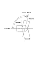
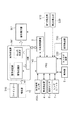
図1は、本発明の実施形態に係る撮像システムを用いてバウンス発光撮影を行っている図である。本発明の実施形態に係る撮像システムは、撮像装置であるカメラ300、カメラ300に着脱可能に装着されたレンズユニット5、カメラ300に着脱可能に装着された照明装置であるストロボ装置200を含む。図2は、本発明の実施形態に係るストロボ装置200の概略構成を示す図、図3は、本発明の実施形態に係るカメラ300の概略構成を示す図であって、図1、図2、図3において同一のものは同じ符号をつけている。
(First embodiment)
FIG. 1 is a diagram in which bounce flash photography is performed using an imaging system according to an embodiment of the present invention. The imaging system according to the embodiment of the present invention includes a camera 300 that is an imaging device, a lens unit 5 that is detachably attached to the camera 300, and a strobe device 200 that is an illumination device that is detachably attached to the camera 300. 2 is a diagram illustrating a schematic configuration of a strobe device 200 according to the embodiment of the present invention, and FIG. 3 is a diagram illustrating a schematic configuration of a camera 300 according to the embodiment of the present invention. In FIG. 3, the same components are denoted by the same reference numerals.

図1では、ストロボ装置200からの光を天井101に反射させ、その反射光で被写体100を照らしていて、図1において、ストロボ装置200から照射される光束の中心を実線で示している。実際にストロボ装置200から照射される光束は幅を持っていて、天井101で反射されると多方向に拡散する。しかしながら、説明を簡単にするため、照射される光束の中心の光(照射光軸の中心を通る光)のうち被写体100に到達する光を代表して図1に示している。   In FIG. 1, the light from the strobe device 200 is reflected on the ceiling 101, and the subject 100 is illuminated with the reflected light. In FIG. 1, the center of the light beam emitted from the strobe device 200 is indicated by a solid line. The light beam actually emitted from the strobe device 200 has a width, and when reflected by the ceiling 101, it diffuses in multiple directions. However, for the sake of simplicity, the light that reaches the subject 100 among the light at the center of the irradiated light beam (light that passes through the center of the irradiation optical axis) is shown in FIG.

ストロボ装置200から照射される光束は中心が最も強度が強く、照射される光束の中心の光が被写体100に向かう角度によって被写体100に生じる陰影が異なる。例えば、図1に示すように被写体100がストロボ装置200に比較的近い場合、ストロボ装置200から天井101に向けて光を照射すると、天井101で反射された光は被写体100に対して真上または真上に近い角度から入射する。このような角度で被写体100に光が入射すると、被写体100の鼻の下や首などに影が生じやすい。そこで、図1のように、被写体100の存在する側とは反対側にストロボ装置200から光を照射し、天井101で反射された光で被写体100を照らすことで、被写体100の鼻の下や首などの影が軽減される。   The center of the light beam emitted from the strobe device 200 has the strongest intensity, and the shadow produced on the subject 100 differs depending on the angle at which the light at the center of the emitted light beam is directed toward the subject 100. For example, when the subject 100 is relatively close to the strobe device 200 as shown in FIG. 1, when light is emitted from the strobe device 200 toward the ceiling 101, the light reflected by the ceiling 101 is directly above the subject 100 or Incident from an angle close to directly above. When light is incident on the subject 100 at such an angle, a shadow is likely to occur on the subject 100 under the nose or neck. Therefore, as shown in FIG. 1, light is emitted from the strobe device 200 to the side opposite to the side where the subject 100 exists, and the subject 100 is illuminated with the light reflected by the ceiling 101, so that Shadows such as the neck are reduced.

しかしながら、被写体100の存在する側の反対側には撮影者が存在する場合もあり、被写体100の存在する側とは反対側にストロボ装置200から光を照射すると、撮影者にストロボ装置200から発せられた光が当たって撮影者が不快に感じるおそれがある。   However, there may be a photographer on the side opposite to the side where the subject 100 exists. When light is emitted from the strobe device 200 on the side opposite to the side where the subject 100 exists, the photographer emits light from the strobe device 200. The photographer may feel uncomfortable when exposed to light.

そこで、本実施形態では、被写体100の存在する側とは反対側に撮影者が存在する可能性が高い場合と被写体100の存在する側とは反対側に撮影者が存在する可能性が低い場合とで、ストロボ装置200からの光の照射方向の制限を変える。以下では、被写体100の存在する側とは反対側に撮影者が存在する可能性が高い場合と被写体100の存在する側とは反対側に撮影者が存在する可能性が低い場合とで、ストロボ装置200からの光の照射方向の制限を変える例を説明する。   Therefore, in the present embodiment, there is a high possibility that a photographer exists on the side opposite to the side where the subject 100 exists, and a low possibility that a photographer exists on the side opposite to the side where the subject 100 exists. The limit of the direction of light irradiation from the strobe device 200 is changed. In the following, there is a case in which there is a high possibility that a photographer is present on the side opposite to the side where the subject 100 is present, and a case where a photographer is unlikely to be present on the side opposite to the side where the subject 100 is present. An example of changing the limit of the irradiation direction of light from the apparatus 200 will be described.

次に、図2を用いてストロボ装置200の説明をする。   Next, the strobe device 200 will be described with reference to FIG.

ストロボ装置200は、電池202が装着されることにより電源回路203が作動し、ストロボ装置200を制御する制御部201に電源が供給される。   In the strobe device 200, the power supply circuit 203 is activated when the battery 202 is attached, and power is supplied to the control unit 201 that controls the strobe device 200.

制御部201は、CPU、ROM、RAMなどにより構成され、ストロボ装置200全体を制御する。また、制御部201は、SW回路210の状態に応じて各種処理を実行する。制御部201は、SW回路210におけるMENUスイッチがユーザにより押下されると、表示回路215によりLCD217をパラメータ設定モード表示とする。そして、制御部201は、ダイアルユニット212やSETスイッチに対するユーザの操作によって、制御に必要なパラメータを設定する。ダイアルユニット212には回転方向によってパルスの出方が変わるDIAL1、及びDIAL2の切片があり、回転方向と回転数を収得する事により、スムーズにパラメータの変更が行えるようになっている。また、SW回路210におけるMENUスイッチを操作することによって、ユーザは後述するオートバウンスモードを選択することができる。   The control unit 201 includes a CPU, a ROM, a RAM, and the like, and controls the entire flash device 200. Further, the control unit 201 executes various processes according to the state of the SW circuit 210. When the MENU switch in the SW circuit 210 is pressed by the user, the control unit 201 causes the display circuit 215 to display the LCD 217 in the parameter setting mode. And the control part 201 sets the parameter required for control by the user's operation with respect to the dial unit 212 or the SET switch. The dial unit 212 has intercepts of DIAL1 and DIAL2 whose pulse output changes depending on the rotation direction. By acquiring the rotation direction and the number of rotations, parameters can be changed smoothly. Further, by operating the MENU switch in the SW circuit 210, the user can select an auto bounce mode to be described later.

さらに、制御部201は、ワイヤレスセレクター211の状態により、ワイヤレスモードでの作動状態を設定する。ワイヤレスモードでは通信回路213内の無線通信モジュール(RF−u)により無線通信が行われる。ワイヤレスセレクター211の状態がOFFのときはワイヤレスモードで動作しない。ワイヤレスセレクター211の状態がMASTERのときはマスターとして動作する。ワイヤレスセレクター211の状態がSLAVEのときはスレーブとして動作する。複数のストロボ装置を使った多灯発光撮影を行う際に、複数のストロボ装置の制御を行う機器(MASTER機)となるのかMASTER機の指示に従って動作する機器(SLAVE機)となるのかを設定する。   Further, the control unit 201 sets the operating state in the wireless mode according to the state of the wireless selector 211. In the wireless mode, wireless communication is performed by the wireless communication module (RF-u) in the communication circuit 213. When the state of the wireless selector 211 is OFF, it does not operate in the wireless mode. When the state of the wireless selector 211 is MASTER, it operates as a master. When the state of the wireless selector 211 is SLAVE, it operates as a slave. When performing multiple flash photography using multiple strobe devices, set whether the device will be a device that controls the multiple strobe devices (MASTER) or a device that operates according to the instructions of the MASTER (SLAVE) .

充電回路204は、発光部の光源であるXe管206を発光させるためのエネルギーをコンデンサに蓄積させるための充電を行う。なお、光源はXe管206以外であってもよく、LEDなどでもよい。LEDを発光させるためのエネルギーを蓄積しない構成の場合は充電回路204は不要であり、LEDを発光させるためのエネルギーを蓄積する構成の場合はLEDを発光させるためのエネルギーを蓄積するのに適した蓄電素子を用いればよい。   The charging circuit 204 performs charging for causing the capacitor to store energy for causing the Xe tube 206 that is a light source of the light emitting unit to emit light. The light source may be other than the Xe tube 206, and may be an LED or the like. The charging circuit 204 is unnecessary in the case of a configuration that does not store energy for causing the LED to emit light, and is suitable for storing energy for causing the LED to emit light in a configuration that stores energy for causing the LED to emit light. A power storage element may be used.

表示回路215、LED216やLCD217を制御し、充電が完了するとLED216を点灯させたり、LCD217に充電が完了したことを示す情報を表示させる。   The display circuit 215, the LED 216, and the LCD 217 are controlled, and when charging is completed, the LED 216 is turned on, or information indicating that charging is completed is displayed on the LCD 217.

接続部214は、ストロボ装置200をカメラ300に着脱可能に装着させる部分であり接続端子を有している。この接続端子がカメラ300の有するストロボ接続端子20に接続されるより、カメラ300とストロボ装置200との通信が可能となる。   The connection unit 214 is a part for detachably attaching the strobe device 200 to the camera 300 and has a connection terminal. Since the connection terminal is connected to the strobe connection terminal 20 of the camera 300, the camera 300 and the strobe device 200 can communicate with each other.

背面検知センサ220は、赤外LEDと検知センサがモジュール化された構成となっており、物体等が近接した場合に赤外光が物体に反射され、検知センサでの受光量によって物体を検知できるようになっている。なお、所定の検知範囲内の物体を検知することができる構成であれば、赤外LEDと受光部以外の公知の構成、例えば、照度センサや静電センサ等を用いた構成を背面検知部としてよい。また、物体までの距離を測定するセンサも、測定した距離から物体が所定の検知範囲内にあるか否かがわかるので、所定の検知範囲内にある物体を検知するためのセンサに含まれる。物体までの距離を測定するセンサを用いる場合、センサの測定結果(センサの出力)に基づいて、所定の検知範囲内に物体を検知しているか否かを判定すればよい。背面検知センサ220は、ストロボ装置200を接続部214を介してカメラ300に装着している状態にて、被写体側の面とは反対側の面(背面)に配置されている。   The back surface detection sensor 220 has a configuration in which an infrared LED and a detection sensor are modularized. When an object or the like approaches, infrared light is reflected by the object, and the object can be detected based on the amount of light received by the detection sensor. It is like that. In addition, if it is the structure which can detect the object in a predetermined detection range, well-known structures other than infrared LED and a light-receiving part, for example, the structure using an illuminance sensor, an electrostatic sensor, etc. as a back surface detection part. Good. A sensor for measuring the distance to the object is also included in the sensor for detecting an object within the predetermined detection range because it can be determined from the measured distance whether the object is within the predetermined detection range. When a sensor that measures the distance to an object is used, it may be determined based on the sensor measurement result (sensor output) whether or not the object is detected within a predetermined detection range. The back surface detection sensor 220 is disposed on a surface (back surface) opposite to the surface on the subject side in a state where the strobe device 200 is attached to the camera 300 via the connection unit 214.

ストロボ装置200は、後述するように、接続部214や背面検知センサ220を有する本体部とXe管206を有する可動部とに分かれている。バウンス駆動回路207は、モーター208を駆動して可動部を本体部に対して相対的に上下方向及び左右方向に回動させる。また、バウンス駆動回路207は、ロータリーエンコーダやアブソリュートエンコーダを用いた位置検出回路209の出力により、可動部の回動状態を検出する。   As will be described later, the strobe device 200 is divided into a main body having a connection part 214 and a back surface detection sensor 220 and a movable part having an Xe tube 206. The bounce drive circuit 207 drives the motor 208 to rotate the movable part in the up and down direction and the left and right direction relative to the main body part. Further, the bounce drive circuit 207 detects the rotation state of the movable part based on the output of the position detection circuit 209 using a rotary encoder or an absolute encoder.

測距回路221は、ストロボ装置200からの光が照射される方向に存在する対象物のストロボ装置200からの距離に関する情報を取得する。距離に関する情報を取得する方法は限定されないが、例えば、光源と受光センサとを用いて、光源を発光させ対象物で反射された光を受光センサで受光し、受光した光量から距離に関する情報を演算して取得する方法を適用すればよい。その他、光源から赤外線を対象物に照射し、赤外線を照射してから受光センサで赤外線を検知するまでの時間から距離に関する情報を演算する方法を適用してもよい。測距回路221は、ストロボ装置200から対象物までの距離に関する情報を取得するための電子部品を有していればよく、上述した光源と受光センサは一例である。   The distance measuring circuit 221 acquires information related to the distance from the strobe device 200 of an object existing in the direction in which the light from the strobe device 200 is irradiated. The method for acquiring information related to distance is not limited. For example, using a light source and a light receiving sensor, the light emitted from the light source and reflected by the object is received by the light receiving sensor, and the distance related information is calculated from the received light quantity. Then, the method of obtaining it can be applied. In addition, a method may be applied in which information about distance is calculated from the time from irradiating an object with infrared rays from a light source and irradiating the infrared rays until the light receiving sensor detects the infrared rays. The distance measuring circuit 221 only needs to have an electronic component for acquiring information regarding the distance from the strobe device 200 to the object, and the light source and the light receiving sensor described above are examples.

次に、図2を用いてカメラ300の説明をする。   Next, the camera 300 will be described with reference to FIG.

カメラ300は、全体の制御を行うマイコンPRS140と、CCDまたはCMOSエリアセンサ等からなる撮像部13とを有している。また、撮像部13から入力された画像信号を処理する画像処理部141、画像を表示する画像表示部401、複数の画像データを保存する不揮発性の記憶部材からなる外部記憶装置9等も有している。   The camera 300 includes a microcomputer PRS140 that performs overall control, and an imaging unit 13 that includes a CCD or CMOS area sensor. The image processing unit 141 that processes an image signal input from the imaging unit 13, an image display unit 401 that displays an image, an external storage device 9 that includes a non-volatile storage member that stores a plurality of image data, and the like. ing.

マイコンPRS140は、例えば、内部にCPU(中央演算処理部)、RAM、ROM、不揮発性メモリ、入出力ポート等が配置されたワンチップのコンピュータ(以下、マイコンと略記する)である。   The microcomputer PRS 140 is, for example, a one-chip computer (hereinafter abbreviated as a microcomputer) in which a CPU (central processing unit), RAM, ROM, nonvolatile memory, input / output port, and the like are arranged.

マイコン140は、ROMに格納されたシーケンスプログラムに基づいて一連の動作を行う。また、マイコン140に内蔵されている不揮発性メモリには、一連のパラメータが格納されている。例えば、露出制御や焦点調節に関する調整値等を含む一連のカメラの制御パラメータや、撮像素子の調整値、撮像画像のホワイトバランスから画像表示部401に撮像画像を表示する際の制御値のデータなどのパラメータが格納されている。このように、画像処理の制御、調整に関係する一連のパラメータが不揮発性メモリに格納されている。   The microcomputer 140 performs a series of operations based on a sequence program stored in the ROM. In addition, a series of parameters are stored in the nonvolatile memory built in the microcomputer 140. For example, a series of camera control parameters including adjustment values related to exposure control and focus adjustment, image sensor adjustment values, control value data for displaying a captured image on the image display unit 401 from the white balance of the captured image, etc. The parameters are stored. In this way, a series of parameters related to control and adjustment of image processing are stored in the nonvolatile memory.

撮像部13は、CCDまたはCMOSエリアセンサ等の撮像素子と該撮像素子を駆動するセンサ駆動部とからなる。撮像素子は、レンズユニット5の光学系を通じて撮像素子上に結像された光学像を光電変換し、電気信号として画像処理部141へ出力する。   The imaging unit 13 includes an imaging device such as a CCD or CMOS area sensor and a sensor driving unit that drives the imaging device. The imaging device photoelectrically converts an optical image formed on the imaging device through the optical system of the lens unit 5 and outputs the optical image to the image processing unit 141 as an electrical signal.

画像処理部141は、画像補正部、インターフェイス(IF)部、表示画生成部から構成されていて、撮像部13からの撮像素子出力に一連の処理を行っている。画像補正部は、A/D変換機能を備え、撮像部13から入力された電気信号をA/D変換し、暗電流補正やシェーディング補正など、撮像部13に起因する一連の補正を行う。   The image processing unit 141 includes an image correction unit, an interface (IF) unit, and a display image generation unit, and performs a series of processes on the image sensor output from the imaging unit 13. The image correction unit has an A / D conversion function, performs A / D conversion on the electrical signal input from the imaging unit 13, and performs a series of corrections caused by the imaging unit 13, such as dark current correction and shading correction.

画像処理部141では、ローパスフィルタによりノイズ成分を除去し、画素及び色補間処理、ホワイトバランスやガンマ補正等、いわゆる画像そのものに関する一連の画像処理を行う。IF部では、一連の画像処理を行った画像データを後述する外部記憶装置9へ送り出したり、外部記憶装置9に記録された画像データを読み出したりする。   The image processing unit 141 removes noise components using a low-pass filter, and performs a series of image processing related to a so-called image itself, such as pixel and color interpolation processing, white balance and gamma correction. The IF unit sends image data that has undergone a series of image processing to an external storage device 9 to be described later, and reads image data recorded in the external storage device 9.

また、画像処理部141では、画像処理された画像データや、外部記憶装置9に記憶された画像データに対して表示のための一連の処理を行い、IF部を介して画像表示部401へ出力する。なお、IF部から画像表示部401へ画像データを出力するまでの一連の処理は、表示画生成部内のリサイズ部、VRAM部を経由して行われる。   Further, the image processing unit 141 performs a series of processes for display on the image data subjected to image processing and the image data stored in the external storage device 9, and outputs the processed image data to the image display unit 401 via the IF unit. To do. Note that a series of processing until the image data is output from the IF unit to the image display unit 401 is performed via the resize unit and the VRAM unit in the display image generation unit.

画像表示部401は、LCD制御部とLCD表示部で構成され、画像処理部141にてLCD表示向けの画像サイズに調整された画像データにLCD表示向けに、輝度、コントラスト、γの各調整を行い、LCDに表示する。   The image display unit 401 includes an LCD control unit and an LCD display unit. The image processing unit 141 adjusts brightness, contrast, and γ for the LCD display to the image data adjusted to the image size for the LCD display. And display on LCD.

画像表示部401に表示される対象となる画像データは、前述した撮像部13で撮像を行い得られた画像データのほかに、外部記憶装置9に記憶した画像データや、カメラの設定情報がある。   The image data to be displayed on the image display unit 401 includes image data stored in the external storage device 9 and camera setting information in addition to the image data obtained by the imaging unit 13 described above. .

また、画像表示部401は、撮像部13で連続的に撮像して得られた画像データを逐次表示する、いわゆるライブビュー表示も可能である。   The image display unit 401 can also perform so-called live view display in which image data obtained by continuously capturing images with the image capturing unit 13 is sequentially displayed.

外部記憶装置9は、例えば、CFカードのような複数の画像データを保存することができる不揮発性の記憶部材であって、カメラ300から着脱可能なものである。そして、カメラに装着した状態で画像処理部141から出力される画像データを記憶する。これにより、1つまたは複数の画像データを記憶した後に、カメラから取り外して、本システムのデータ形式で読み出し可能な別のシステムに装着すれば、記憶されている撮影画像データの再生、編集、及び保存が可能となる。   The external storage device 9 is a non-volatile storage member that can store a plurality of image data, such as a CF card, and is detachable from the camera 300. Then, the image data output from the image processing unit 141 while being mounted on the camera is stored. As a result, after storing one or a plurality of image data, if it is detached from the camera and attached to another system that can be read out in the data format of this system, the stored captured image data can be reproduced, edited, and Saving is possible.

焦点検出部4は、結像面近傍に配置されたフィールドレンズ、反射ミラー、2次結像レンズ、絞り、及び複数の光電変換素子からなるCCD等のラインセンサから構成されている。本実施形態における焦点検出部4は、周知の位相差方式であるとともに、観察画面内(ファインダ視野内)の複数の領域を焦点検出点として、該焦点検出点で焦点を検出することが可能となるように構成されている。   The focus detection unit 4 includes a field lens, a reflection mirror, a secondary imaging lens, a diaphragm, and a line sensor such as a CCD including a plurality of photoelectric conversion elements arranged in the vicinity of the imaging surface. The focus detection unit 4 in the present embodiment is a well-known phase difference method, and can detect a focus at the focus detection point using a plurality of regions in the observation screen (in the viewfinder field) as focus detection points. It is comprised so that it may become.

測光センサ8は、CCDまたはCMOSエリアセンサ等の撮像素子を用いた被写体の測光を行うためのセンサであり、観察画面内(ファインダ視野内)の複数の領域を測光領域として、該測光領域で測光を行うことが可能となるように構成されている。   The photometric sensor 8 is a sensor for performing photometry of a subject using an image sensor such as a CCD or CMOS area sensor. A plurality of areas in the observation screen (in the viewfinder field) are set as photometric areas, and photometry is performed in the photometric areas. It is comprised so that it can perform.

操作部6は、焦点検出や測光などの撮像準備動作を指示したり(SW1 ON)撮像動作を指示したり(SW2 ON)するレリーズボタンや、カメラ300の動作モードや各種設定を行うための設定ボタンなどを含んでいる。マイコン140は、操作部6へのユーザの操作に応じてカメラ300を制御する。   The operation unit 6 is a release button for instructing an imaging preparation operation such as focus detection or photometry (SW1 ON) or an imaging operation (SW2 ON), a setting for performing an operation mode or various settings of the camera 300. Includes buttons. The microcomputer 140 controls the camera 300 in accordance with a user operation on the operation unit 6.

レンズユニット5には、焦点調節回路及び絞り駆動回路が組み込まれており、不図示のマウント接点を介してマイコンPRS140と信号の伝達がなされる。マイコン140は、焦点検出部4から出力される信号に基づき、レンズユニット5に内蔵されている焦点調節回路を動作して、最適な焦点調節となる信号を出力する。さらに、測光センサから出力される信号に基づいて、レンズユニット5に内蔵されている絞り駆動回路を動作して、最適な露光量となる信号を出力する。   The lens unit 5 incorporates a focus adjustment circuit and a diaphragm drive circuit, and transmits signals to and from the microcomputer PRS 140 via a mount contact (not shown). The microcomputer 140 operates a focus adjustment circuit built in the lens unit 5 based on the signal output from the focus detection unit 4 and outputs a signal for optimal focus adjustment. Further, based on the signal output from the photometric sensor, the aperture driving circuit built in the lens unit 5 is operated to output a signal that provides an optimum exposure amount.

ファインダー310は、被写体側の面とは反対側の面(背面)に配置されていて、レンズユニット5を通して得られる光学像を、撮影者が目視により確認できる窓である。なお、ファインダー310は、レンズユニット5を通して得られる光学像の代わりに、撮像部13で撮像を行い得られた画像データを表示させる表示部を有している、いわゆる電子ファインダーでもよい。   The viewfinder 310 is a window that is disposed on a surface (back surface) opposite to the surface on the subject side, and allows a photographer to visually confirm an optical image obtained through the lens unit 5. The viewfinder 310 may be a so-called electronic viewfinder having a display unit that displays image data obtained by imaging with the imaging unit 13 instead of the optical image obtained through the lens unit 5.

背面検知センサ800は、被写体側の面とは反対側の面(背面)のファインダー310の近傍に配置されていて、所定の検知範囲内の物体を検知することができるセンサである。なお、背面検知センサ800は、ストロボ装置200の背面検知センサ220と同様の構成でよいため説明は省略する。   The back surface detection sensor 800 is a sensor that is disposed in the vicinity of the viewfinder 310 on the surface (back surface) opposite to the surface on the subject side, and can detect an object within a predetermined detection range. Note that the back surface detection sensor 800 may have the same configuration as the back surface detection sensor 220 of the strobe device 200, and thus description thereof is omitted.

リモートコントロール部600は、受信部610と送信部620で構成され、受信部610と送信部620とで電波や赤外線などを用いた無線通信を行うことで、カメラ300の遠隔操作を行う。送信部620は、カメラ300を遠隔操作するためのボタンやスイッチを含む操作部及び操作部の状態に関する情報を受信部610に送信するための送信回路を有している。送信回路には、電波による無線通信を行う構成であればアンテナなどの無線通信モジュールを有し、赤外線による無線通信を行う構成であれば赤外線LEDを有している。受信部610は、電波による無線通信を行う構成であればアンテナなどの無線通信モジュールを有し、赤外線による無線通信を行う構成であれば赤外線受光センサを有している。リモートコントロール部600を用いた遠隔操作では、送信部620を操作することで、操作部6のレリーズボタンが操作されたときと同様に撮像準備動作の指示や撮像動作の指示を行うことができる。受信部610は、カメラ300の被写体側の面に設けられていて、受信部610で受信した情報は、マイコン140へ伝達される。   The remote control unit 600 includes a reception unit 610 and a transmission unit 620, and performs remote operation of the camera 300 by performing wireless communication using radio waves or infrared rays between the reception unit 610 and the transmission unit 620. The transmission unit 620 includes an operation unit including buttons and switches for remotely operating the camera 300 and a transmission circuit for transmitting information regarding the state of the operation unit to the reception unit 610. The transmission circuit has a wireless communication module such as an antenna if it is configured to perform wireless communication using radio waves, and an infrared LED if configured to perform wireless communication using infrared rays. The receiving unit 610 has a wireless communication module such as an antenna if configured to perform wireless communication using radio waves, and an infrared light receiving sensor if configured to perform wireless communication using infrared rays. In the remote operation using the remote control unit 600, by operating the transmission unit 620, an instruction for an imaging preparation operation and an instruction for an imaging operation can be performed in the same manner as when the release button of the operation unit 6 is operated. The receiving unit 610 is provided on the subject-side surface of the camera 300, and information received by the receiving unit 610 is transmitted to the microcomputer 140.

続いて、図4を用いて、ストロボ装置200における本体部に対する可動部の回動角度を説明する。以下では、ストロボ装置200でXe管206からの光の照射方向(発光部の照射方向)を決定し、決定された照射方向となるようにバウンス駆動回路207を用いて可動部を本体部に対して相対的に回動させることをオートバウンスと呼ぶ。また、オートバウンスを行うモードをオートバウンスモードと呼ぶ。   Next, the rotation angle of the movable part with respect to the main body part in the strobe device 200 will be described with reference to FIG. In the following, the irradiation direction of the light from the Xe tube 206 (irradiation direction of the light emitting unit) is determined by the strobe device 200, and the movable unit is moved with respect to the main body unit using the bounce drive circuit 207 so as to be the determined irradiation direction. This relative rotation is called auto bounce. A mode in which auto bounce is performed is called an auto bounce mode.

図4に記載された「Home position」(基準位置)は、ストロボ装置200をカメラ300に装着させた状態において、カメラ300の撮影光軸とストロボ装置200の照射光軸とが平行になる可動部の回動角度を示している。この「Home position」における本体部に対する可動部の回動角度を上下方向に0度、左右方向に0度とする。本実施形態では、可動部を回動させるときの回動角度を制限する制限角度として、角度θL(第1の角度)と角度θN(第2の角度)が設定できる。図4に示すように、角度θLは角度θNよりも小さい角度であって、本実施形態では角度θLを90度、角度θNを120度としている。角度θLの値は90度に限定されるものではないが、撮影者にストロボ装置200から発せられた光が当たりにくくするために90度以下が好ましい。また、角度θNの値も120度に限定されるものではないが、可動部を回動させるときの自由度を高めるためにメカ構成によって決まる最大回動角度に近い角度が好ましい。   The “Home position” (reference position) shown in FIG. 4 is a movable part in which the photographing optical axis of the camera 300 and the irradiation optical axis of the strobe device 200 are parallel when the strobe device 200 is mounted on the camera 300. The rotation angle is shown. In this “Home position”, the rotation angle of the movable part with respect to the main body is set to 0 degrees in the vertical direction and 0 degrees in the horizontal direction. In the present embodiment, an angle θL (first angle) and an angle θN (second angle) can be set as the limiting angle for limiting the rotation angle when rotating the movable part. As shown in FIG. 4, the angle θL is smaller than the angle θN, and in this embodiment, the angle θL is 90 degrees and the angle θN is 120 degrees. The value of the angle θL is not limited to 90 degrees, but is preferably 90 degrees or less in order to make it difficult for the photographer to be exposed to the light emitted from the strobe device 200. Further, the value of the angle θN is not limited to 120 degrees, but an angle close to the maximum rotation angle determined by the mechanical configuration is preferable in order to increase the degree of freedom when the movable part is rotated.

なお、本実施形態におけるストロボ装置200は、可動部が「Home position」から最大で上方向に120度、下方向に5度、左右方向にそれぞれ180度まで可動可能なように構成されているものとする。可動部が本体部に対して上下方向と左右方向に回動可能な構成は、例えば特開2015−049280号公報に記載されているような構成にすればよく、詳細な説明は省略する。   The strobe device 200 according to the present embodiment is configured such that the movable part can move up to 120 degrees upward, 5 degrees downward, and 180 degrees horizontally from the "Home position". And A configuration in which the movable portion can rotate in the vertical direction and the horizontal direction with respect to the main body portion may be a configuration as described in, for example, Japanese Patent Application Laid-Open No. 2015-049280, and detailed description thereof is omitted.

オートバウンス発光撮影を行う際にバウンス駆動回路207を用いて可動部を回動させる場合、制限角度が角度θLに設定されていると、「Home position」から角度θLまでの角度領域Aに含まれる回動角度となるように可動部が回動される。また、制限角度が角度θNに設定されていると、「Home position」から角度θNの角度領域Bに含まれる回動角度となるように可動部が回動される。   When the movable part is rotated using the bounce drive circuit 207 when performing auto bounce flash photography, if the limit angle is set to the angle θL, it is included in the angle region A from “Home position” to the angle θL. The movable part is rotated so as to have a rotation angle. When the limit angle is set to the angle θN, the movable portion is rotated so that the rotation angle is included in the angle region B of the angle θN from “Home position”.

以上のような、可動部を回動させるときの回動角度を制限する制限角度を設定する処理を含めたオートバウンス発光撮影に係わる処理を、図5、図6を用いて説明する。   Processing related to auto bounce flash photography including processing for setting a limit angle for limiting the rotation angle when the movable portion is rotated will be described with reference to FIGS. 5 and 6.

ストロボ装置200をカメラ300に装着し、カメラ300の電源がオンになると、ステップS10にてマイコン140は、撮影に関わる一連の初期設定を行う。   When the strobe device 200 is attached to the camera 300 and the power of the camera 300 is turned on, the microcomputer 140 performs a series of initial settings related to photographing in step S10.

ステップS20にてマイコン140は、発光モードなどストロボ装置200に関わる情報(ストロボ情報)の初期化を行う。ストロボ装置200の電源がオンになると、ステップS30にてマイコン140は、ストロボ装置200との通信を行って装着しているストロボ装置200に関する情報を取得する。   In step S20, the microcomputer 140 initializes information (strobe information) related to the strobe device 200 such as the light emission mode. When the power of the strobe device 200 is turned on, in step S30, the microcomputer 140 communicates with the strobe device 200 and acquires information regarding the attached strobe device 200.

次に、ステップS40にてマイコン140は、バウンス駆動回路207に指示して、可動部を図4に示した「Home position」に移動させる。なお、可動部がすでに「Home position」に位置する場合は、本ステップは省略される。   Next, in step S40, the microcomputer 140 instructs the bounce drive circuit 207 to move the movable part to “Home position” shown in FIG. It should be noted that this step is omitted when the movable part is already positioned at “Home position”.

ステップS50にてマイコン140は、操作部6のレリーズボタンが操作されてSW1がONになったか否かを判別する。操作部6のレリーズボタンが操作されてSW1がONになった場合はステップS60へ移行し、操作部6のレリーズボタンが操作されてSW1がONになっていない場合はステップS80へ移行する。   In step S50, the microcomputer 140 determines whether the release button of the operation unit 6 is operated and SW1 is turned on. If the release button of the operation unit 6 is operated and SW1 is turned on, the process proceeds to step S60. If the release button of the operation unit 6 is operated and SW1 is not turned on, the process proceeds to step S80.

ステップS60にてマイコン140は、背面検知センサ800で物体を検知しているか否かを判別する。なお、背面検知センサ800は、定期的に物体の検知動作を行ってもよいし、ステップS60にて物体の検知動作を行ってもよい。背面検知センサ800で物体を検知している場合はステップS90へ移行し、物体を検知していない場合はステップS70へ移行する。   In step S60, the microcomputer 140 determines whether or not an object is detected by the back surface detection sensor 800. Note that the back surface detection sensor 800 may periodically perform an object detection operation, or may perform an object detection operation in step S60. When the object is detected by the back surface detection sensor 800, the process proceeds to step S90, and when the object is not detected, the process proceeds to step S70.

ステップS70にてマイコン140は、ストロボ装置200と通信し、背面検知センサ220で物体を検知しているか否かを判別する。背面検知センサ220は、背面検知センサ800と同様に、定期的に物体の検知動作を行ってもよいし、ステップS60にて物体の検知動作を行ってもよい。背面検知センサ800で物体を検知している場合はステップ90へ移行し、物体を検知していない場合はステップS100へ移行する。   In step S <b> 70, the microcomputer 140 communicates with the strobe device 200 and determines whether or not an object is detected by the back surface detection sensor 220. Similar to the back surface detection sensor 800, the back surface detection sensor 220 may periodically perform an object detection operation, or may perform an object detection operation in step S60. When the object is detected by the back surface detection sensor 800, the process proceeds to step 90, and when the object is not detected, the process proceeds to step S100.

ステップS50にて操作部6のレリーズボタンが操作されてSW1がONになっていないと判別した場合、ステップS80にてマイコン140は、リモートコントロール部600の送信部620が操作されてSW1がONになったか否かを判別する。リモートコントロール部600の送信部620が操作されてSW1がONになった場合はステップS90へ移行し、リモートコントロール部600の送信部620が操作されてSW1がONになっていない場合はステップS50へ移行する。   If it is determined in step S50 that the release button of the operation unit 6 is operated and SW1 is not turned on, in step S80, the microcomputer 140 operates the transmission unit 620 of the remote control unit 600 and turns SW1 on. It is determined whether or not. When the transmission unit 620 of the remote control unit 600 is operated and SW1 is turned on, the process proceeds to step S90. When the transmission unit 620 of the remote control unit 600 is operated and SW1 is not turned on, the process proceeds to step S50. Transition.

ステップS90にてマイコン140は、可動部を回動させるときの回動角度を制限する制限角度を角度θNに設定し、ストロボ装置200に設定した制限角度に関する情報を送信する。   In step S <b> 90, the microcomputer 140 sets the angle θN as the limit angle that limits the rotation angle when rotating the movable part, and transmits information regarding the set limit angle to the strobe device 200.

ステップS100にてマイコン140は、可動部を回動させるときの回動角度を制限する制限角度θLに設定し、ストロボ装置200に設定した制限角度に関する情報を送信する。   In step S <b> 100, the microcomputer 140 sets a limit angle θL that limits a rotation angle when the movable part is rotated, and transmits information regarding the set limit angle to the strobe device 200.

ステップS110にてマイコン140は、ストロボ装置200へオートバウンスの実行指示を送信する。また、ステップS110にてマイコン140は、ストロボ装置200へオートバウンスの実行指示を送信する前に各部に指示して焦点検出や測光などの撮影準備動作を行わせる。   In step S110, the microcomputer 140 transmits an auto bounce execution instruction to the strobe device 200. In step S110, the microcomputer 140 instructs each unit to perform photographing preparation operations such as focus detection and photometry before transmitting an auto-bounce execution instruction to the flash device 200.

ステップS120にてマイコン140は、操作部6のレリーズボタンあるいはリモートコントロール部600の送信部620が操作されてSW2がONになったか否かを判別する。   In step S120, the microcomputer 140 determines whether the release button of the operation unit 6 or the transmission unit 620 of the remote control unit 600 is operated and SW2 is turned on.

SW2がONになった場合はステップS130へ移行し、SW2がONになっていない場合はステップ150へ移行する。   When SW2 is turned on, the process proceeds to step S130, and when SW2 is not turned on, the process proceeds to step 150.

ステップS130にてマイコン140は、ストロボ装置200から、ストロボ装置200からの光の照射方向がバウンス発光撮影に適した方向となるように可動部を回動させたことを示すオートバウンス完了通知を受信しているか否かを判定する。オートバウンス通知を受信している場合はステップS140へ移行し、オートバウンス通知を受信していない場合はステップS130を繰り返す。   In step S130, the microcomputer 140 receives from the strobe device 200 an auto bounce completion notification indicating that the movable unit has been rotated so that the light irradiation direction from the strobe device 200 is a direction suitable for bounce flash photography. It is determined whether or not. If an auto bounce notification has been received, the process proceeds to step S140. If an auto bounce notification has not been received, step S130 is repeated.

ステップS140にてマイコン140は、各部に指示して撮像動作を行わせる。また、マイコン140は、撮像に合わせてストロボ装置200を発光させるように、ストロボ装置200に発光指示を送信する。   In step S140, the microcomputer 140 instructs each unit to perform an imaging operation. In addition, the microcomputer 140 transmits a light emission instruction to the strobe device 200 so that the strobe device 200 emits light in accordance with imaging.

ステップS150にてマイコン140は、操作部6のレリーズボタンあるいはリモートコントロール部600の送信部620が操作されてSW1がONになっているか否かを判別する。SW1がONになっている場合はステップS120へ移行し、SW2がONになっていない場合はステップS50へ移行する。   In step S150, the microcomputer 140 determines whether the release button of the operation unit 6 or the transmission unit 620 of the remote control unit 600 is operated and SW1 is turned on. If SW1 is ON, the process proceeds to step S120. If SW2 is not ON, the process proceeds to step S50.

以上のようにして、オートバウンス発光撮影が行われる。   As described above, auto bounce flash photography is performed.

次に、カメラ300からオートバウンスの実行指示を受信したストロボ装置200の処理について図6を用いて説明する。図6の処理は、カメラ300からオートバウンスの実行指示を受信すると開始される。   Next, the processing of the strobe device 200 that has received an auto bounce execution instruction from the camera 300 will be described with reference to FIG. The process of FIG. 6 is started when an auto bounce execution instruction is received from the camera 300.

ステップS1010にて制御部201は、バウンス発光撮影に適したストロボ装置200からの光の照射方向を演算するための一連の動作を行う。本実施形態では、ストロボ装置200から被写体までの距離に関する情報とストロボ装置200から被写体とは異なる方向の対象物までの距離に関する情報とに基づいてバウンス発光撮影に適したストロボ装置200からの光の照射方向を演算する方法を用いる。   In step S1010, the control unit 201 performs a series of operations for calculating the irradiation direction of light from the strobe device 200 suitable for bounce flash photography. In the present embodiment, the light from the strobe device 200 suitable for bounce flash photography is based on the information about the distance from the strobe device 200 to the subject and the information about the distance from the strobe device 200 to the object in a direction different from the subject. A method of calculating the irradiation direction is used.

そこで、制御部201は、ストロボ装置200から被写体までの距離に関する情報を取得するために、ストロボ装置200からの光の照射方向が被写体の方向を向くようにバウンス駆動回路207に指示して可動部を回動させる。ストロボ装置200がカメラ300に装着されている場合、可動部が「Home position」に位置しているとストロボ装置200からの光の照射方向が被写体の方向を向くので、「Home position」に位置するよう可動部を回動させる。その後、制御部201は測距回路221を用いてストロボ装置200から被写体までの距離に関する情報を取得する。続いて、ストロボ装置200から被写体とは異なる対象物までの距離に関する情報を取得するために、制御部201は、ストロボ装置200からの光の照射方向が被写体とは異なる対象物の方向を向くようにバウンス駆動回路207に指示して可動部を回動させる。本実施形態では、天井を被写体とは異なる対象物とする例を説明するが、天井の代わりに壁などを対象物にしてもよい。可動部を回動させた後、制御部201は測距回路221を用いてストロボ装置200から天井までの距離に関する情報を取得する。   Therefore, the control unit 201 instructs the bounce drive circuit 207 so that the light irradiation direction from the strobe device 200 is directed to the subject in order to acquire information regarding the distance from the strobe device 200 to the subject. Rotate. When the strobe device 200 is attached to the camera 300, the light irradiation direction from the strobe device 200 faces the direction of the subject when the movable part is positioned at the “Home position”, so the position is at the “Home position”. The movable part is rotated. Thereafter, the control unit 201 uses the distance measuring circuit 221 to acquire information regarding the distance from the flash device 200 to the subject. Subsequently, in order to acquire information regarding the distance from the strobe device 200 to an object different from the subject, the control unit 201 causes the light irradiation direction from the strobe device 200 to be directed to a target different from the subject. The bounce drive circuit 207 is instructed to rotate the movable part. In the present embodiment, an example in which the ceiling is an object different from the subject will be described, but a wall or the like may be used instead of the ceiling. After rotating the movable unit, the control unit 201 uses the distance measuring circuit 221 to acquire information regarding the distance from the strobe device 200 to the ceiling.

次に、取得したストロボ装置200から被写体までの距離に関する情報とストロボ装置200から天井までの距離に関する情報とに基づいてバウンス発光撮影に適したストロボ装置200からの光の照射方向を演算する。   Next, the irradiation direction of light from the strobe device 200 suitable for bounce flash photography is calculated based on the acquired information about the distance from the strobe device 200 to the subject and the information about the distance from the strobe device 200 to the ceiling.

ここで、ストロボ装置200から天井までの距離を距離L1、ストロボ装置200から被写体までの距離を距離L2とする。そして、以下の式(1)を用いて、重力方向に直交する方向を基準にしたバウンス発光撮影に適したストロボ装置200からの光の照射方向を角度θSPを演算する。
TAN(θSP)=L1/(L2/2) ・・・(1)
Here, the distance from the strobe device 200 to the ceiling is the distance L1, and the distance from the strobe device 200 to the subject is the distance L2. Then, using the following equation (1), the angle θSP is calculated for the irradiation direction of light from the strobe device 200 suitable for bounce flash photography based on the direction orthogonal to the direction of gravity.
TAN (θSP) = L1 / (L2 / 2) (1)

次に、ステップS1020にて制御部201は、演算して求めた角度θSPを可動部を回動させるときの目標角度θPに設定する。   Next, in step S1020, the control unit 201 sets the calculated angle θSP to the target angle θP for rotating the movable unit.

ステップS1030にて制御部201は、設定された目標角度θPが可動部を回動させるときの回動角度を制限する制限角度より大きいか否かを判定する。ここで目標角度θPと比較される制限角度は、ステップS90あるいはステップS100でマイコン140により設定され、カメラ300からストロボ装置200に送信された制限角度に関する情報に対応する。例えば、カメラ300からストロボ装置200に送信された制限角度に関する情報が制限角度θNを示す場合は、制御部201は目標角度θPが制限角度θNより大きいか否かを判定する。目標角度θPが制限角度より大きい場合はステップS1040へ移行し、ステップS1040にて制御部201は、制限角度を目標角度に設定する。目標角度θPが制限角度以下の場合はステップS1050へ移行し、目標角度を変更しない。   In step S1030, the control unit 201 determines whether or not the set target angle θP is larger than a limit angle that limits a rotation angle when the movable unit is rotated. Here, the limit angle compared with the target angle θP is set by the microcomputer 140 in step S90 or step S100, and corresponds to information regarding the limit angle transmitted from the camera 300 to the strobe device 200. For example, when the information regarding the limit angle transmitted from the camera 300 to the strobe device 200 indicates the limit angle θN, the control unit 201 determines whether or not the target angle θP is larger than the limit angle θN. When the target angle θP is larger than the limit angle, the process proceeds to step S1040, and in step S1040, the control unit 201 sets the limit angle as the target angle. When the target angle θP is equal to or smaller than the limit angle, the process proceeds to step S1050, and the target angle is not changed.

ステップS1050にて制御部201は、バウンス駆動回路207に指示して可動部を回動させるとともに、位置検出回路209の出力により可動部の回動角度が目標角度θPとなったか否かを判定する。可動部の回動角度が目標角度θPとなっていればステップS1060へ移行し、可動部の回動角度が目標角度θPとなっていなければステップS1050を繰り返す。   In step S1050, the control unit 201 instructs the bounce drive circuit 207 to rotate the movable unit, and determines whether the rotation angle of the movable unit has reached the target angle θP based on the output of the position detection circuit 209. . If the rotation angle of the movable part is the target angle θP, the process proceeds to step S1060. If the rotation angle of the movable part is not the target angle θP, step S1050 is repeated.

ステップS1060にて制御部201は、ストロボ装置200からの光の照射方向がバウンス発光撮影に適した方向となるように可動部を回動させたことを示すオートバウンス完了通知をカメラ300に送信する。   In step S <b> 1060, the control unit 201 transmits to the camera 300 an auto bounce completion notification indicating that the movable unit has been rotated so that the light irradiation direction from the strobe device 200 is a direction suitable for bounce flash photography. .

以上のように、本実施形態では、カメラ300の背面検知センサ800の検知結果及びストロボ装置200の背面検知センサ220の検知結果に基づいて、ストロボ装置200の可動部を回動させるときの回動角度を制限する制限角度を設定している。具体的には、背面検知センサ800と背面検知センサ220のいずれも物体を検知していない場合、背面検知センサ800と背面検知センサ220の少なくとも一方で物体を検知している場合よりも制限角度を小さい角度に設定している。背面検知センサ800と背面検知センサ220のいずれも物体を検知していない場合、撮影者がカメラ300やストロボ装置200から離れていると想定される。そのため、被写体100の存在する側とは反対側にストロボ装置200から光を照射することができるように制限角度を大きい角度にすると、撮影者にストロボ装置200から発せられた光が当たって撮影者が不快に感じるおそれがある。そこで、背面検知センサ800と背面検知センサ220のいずれも物体を検知していない場合、撮影者にストロボ装置200から発せられた光が当たりそうな角度に可動部を回動できないように制限角度を設定する。   As described above, in this embodiment, the rotation when the movable part of the strobe device 200 is rotated based on the detection result of the back surface detection sensor 800 of the camera 300 and the detection result of the back surface detection sensor 220 of the strobe device 200. A limit angle is set to limit the angle. Specifically, when neither the back surface detection sensor 800 nor the back surface detection sensor 220 detects an object, the limit angle is set more than when at least one of the back surface detection sensor 800 and the back surface detection sensor 220 is detecting an object. A small angle is set. When neither the back surface detection sensor 800 nor the back surface detection sensor 220 detects an object, it is assumed that the photographer is away from the camera 300 or the flash device 200. For this reason, when the limit angle is set to a large angle so that light can be emitted from the strobe device 200 on the side opposite to the side where the subject 100 exists, the photographer is exposed to light emitted from the strobe device 200. May feel uncomfortable. Therefore, when neither the back surface detection sensor 800 nor the back surface detection sensor 220 detects an object, the limit angle is set so that the movable portion cannot be rotated to an angle at which the light emitted from the strobe device 200 is likely to hit the photographer. Set.

また、本実施形態では、背面検知センサ800と背面検知センサ220のいずれも物体を検知していない場合であっても、リモートコントロール部600が操作されたことに応じてオートバウンスの開始指示を行う場合には、制限角度を小さい値にしない。リモートコントロール部600が操作されたことに応じてオートバウンスの開始指示を行う場合、撮影者が被写体100の存在する側とは反対側に位置する可能性は低いためである。   Further, in the present embodiment, even when neither the back surface detection sensor 800 nor the back surface detection sensor 220 detects an object, an auto bounce start instruction is issued in response to the operation of the remote control unit 600. In this case, the limit angle is not set to a small value. This is because when the auto bounce start instruction is issued in response to the operation of the remote control unit 600, the photographer is unlikely to be located on the side opposite to the side where the subject 100 exists.

以上のようにストロボ装置200の可動部を回動させるときの回動角度を制限する制限角度を設定することで、ストロボ装置200からの光の照射方向の自由度をできる限り確保し、ストロボ装置200からの光がユーザに照射されることを低減することができる。   As described above, by setting the limit angle for limiting the rotation angle when the movable part of the strobe device 200 is rotated, the degree of freedom in the light irradiation direction from the strobe device 200 is ensured as much as possible, and the strobe device It can reduce that the light from 200 is irradiated to a user.

(第2の実施形態)
本実施形態のカメラ400は、2つの軸を回動中心として回動可能な画像表示部501を有する点で第1の実施形態のカメラ300と異なる。また、本実施形態は、画像表示部501の回動状態に基づいてストロボ装置200の可動部を回動させるときの回動角度を制限する制限角度を設定する点で、第1の実施形態と異なる。なお、本実施形態の撮像システムは、カメラ300の代わりにカメラ400を用いる点が第1の実施形態と異なるだけであり、第1の実施形態のストロボ装置200を用いればよい。
(Second Embodiment)
The camera 400 of this embodiment is different from the camera 300 of the first embodiment in that it has an image display unit 501 that can be rotated about two axes. Further, the present embodiment is different from the first embodiment in that a limit angle for limiting a rotation angle when the movable portion of the strobe device 200 is rotated based on the rotation state of the image display unit 501 is set. Different. Note that the imaging system of the present embodiment is different from the first embodiment only in that the camera 400 is used instead of the camera 300, and the strobe device 200 of the first embodiment may be used.

以下では、第1の実施形態と同様な構成は同じ符号とし、第1の実施形態と重複する処理についての詳細な説明は省略する。   In the following, the same components as those in the first embodiment are denoted by the same reference numerals, and detailed description of the processes that are the same as those in the first embodiment is omitted.

まず、図7を用いてカメラ400の説明をする。   First, the camera 400 will be described with reference to FIG.

カメラ400は、互いに直交する2つの軸を回動中心として回動可能な画像表示部501を被写体側とは反対側の面(背面)に有している。画像表示部501を2つの軸を回動中心として回動可能とする方法は公知の方法を用いればよく、本実施形態では、2つの軸を回動中心として回動可能なヒンジ機構を用いて画像表示部501をカメラ400の本体部分に連結させた構成の例を説明する。   The camera 400 has an image display unit 501 that can be rotated about two axes orthogonal to each other on the surface (back surface) opposite to the subject side. A known method may be used to make the image display unit 501 rotatable about two axes as the rotation center. In this embodiment, a hinge mechanism that can rotate about the two axes is used. An example of a configuration in which the image display unit 501 is connected to the main body of the camera 400 will be described.

また、カメラ400は、画像表示部501の第1の軸を回動中心とした回動状態を検出する第1の検出部510と、画像表示部501の第2の軸を回動中心とした回動状態を検出する第2の検出部520とを有している。第1の検出部510、第2の検出部520の検出方法は公知の方法を用いればよく、例えば、カメラ400の本体部分と画像表示部501のいずれか一方に磁石、他方に磁気センサを設けて、磁気センサの検出結果から回動状態を検出する方法などでよい。あるいは、カメラ400の本体部分と画像表示部501のいずれか一方にパターンが設けられた基板、他方に接点ブラシを設けて、接点ブラシが接しているパターン上の位置によって基板から異なる信号を出力し出力信号から回動状態を検出する方法などでよい。   In addition, the camera 400 has a first detection unit 510 that detects a rotation state with the first axis of the image display unit 501 as the rotation center, and a second axis of the image display unit 501 as the rotation center. And a second detection unit 520 that detects the rotation state. The detection method of the first detection unit 510 and the second detection unit 520 may be a known method. For example, a magnet is provided in one of the main body of the camera 400 and the image display unit 501, and a magnetic sensor is provided in the other. Thus, a method of detecting the rotation state from the detection result of the magnetic sensor may be used. Alternatively, a substrate provided with a pattern on either the main body of the camera 400 or the image display unit 501 and a contact brush provided on the other, and different signals are output from the substrate depending on the position on the pattern where the contact brush is in contact. A method of detecting the rotation state from the output signal may be used.

画像表示部501は、撮像部13で連続的に撮像して得られた画像データを逐次表示する、いわゆるライブビュー表示も可能であり、マイコン140は操作部6へのユーザの操作に応じてライブビューを行うか否か(ライブビューモードにするか否か)を制御する。   The image display unit 501 can also perform so-called live view display in which image data obtained by continuously capturing images with the imaging unit 13 is displayed. The microcomputer 140 performs live display according to a user operation on the operation unit 6. Controls whether to perform the view (whether to enter the live view mode).

図8は、画像表示部501の回動可能な方向を示す図である。図8(a)は、画像表示部501の表示面が被写体側とは反対側を向いていて、画像表示部501の表示面とは反対の面(裏面)がカメラ400の本体部分に対向している状態である。図8(b)は、図8(a)に示す状態から第1の軸を中心に画像表示部501をカメラ400の本体部分から離れる方向に180度回動させ、第2の軸を中心に画像表示部501を表示面が上を向く方向に45度回動させた状態である。   FIG. 8 is a diagram illustrating a direction in which the image display unit 501 can be rotated. In FIG. 8A, the display surface of the image display unit 501 faces away from the subject side, and the surface (back surface) opposite to the display surface of the image display unit 501 faces the main body of the camera 400. It is in a state. 8B, the image display unit 501 is rotated 180 degrees away from the main body of the camera 400 from the state shown in FIG. 8A around the first axis, and the second axis is the center. In this state, the image display unit 501 is rotated 45 degrees in the direction in which the display surface faces upward.

本実施形態では、図8(a)に示す状態を基準状態とすると、画像表示部501は、第1の軸を中心に基準状態からカメラ400の本体部分から離れる方向に180度回動可能とする。また、画像表示部501は、第2の軸を中心に基準状態から表示面が上を向く方向及び下を向く方向にそれぞれ180度回動可能とする。   In the present embodiment, when the state shown in FIG. 8A is the reference state, the image display unit 501 can be rotated 180 degrees in the direction away from the main body portion of the camera 400 from the reference state around the first axis. To do. In addition, the image display unit 501 can rotate 180 degrees from the reference state in the direction in which the display surface faces upward and the direction in which the display surface faces downward, with the second axis as the center.

姿勢検出部700は、例えば、角速度センサやジャイロセンサが用いられ、水平方向の姿勢、垂直方向の姿勢、前後方向の姿勢を検出する。姿勢検出部700により検出された各方向の姿勢に関する姿勢情報はマイコン140に入力される。この姿勢検出部700の検出結果によって、マイコン140は、カメラ400の姿勢を判別することができる。   The posture detection unit 700 uses, for example, an angular velocity sensor or a gyro sensor, and detects a horizontal posture, a vertical posture, and a front-back posture. Posture information regarding the posture in each direction detected by the posture detection unit 700 is input to the microcomputer 140. Based on the detection result of the posture detection unit 700, the microcomputer 140 can determine the posture of the camera 400.

次に、画像表示部501に表示された画像を撮影者が視認できる視認可能範囲とストロボ装置200の制限角度との関係を図9を用いて説明する。   Next, the relationship between the viewable range where the photographer can visually recognize the image displayed on the image display unit 501 and the limit angle of the strobe device 200 will be described with reference to FIG.

図9(a)は、制限角度が角度θNであるときに最大角度まで可動部を回動させた状態を示していて、図9(b)は、制限角度が角度θLであるときに最大角度まで可動部を回動させた状態を示している。   FIG. 9A shows a state where the movable portion is rotated to the maximum angle when the limit angle is the angle θN, and FIG. 9B shows the maximum angle when the limit angle is the angle θL. The state where the movable part is rotated is shown.

また、図9(a)、図9(b)はともに、画像表示部501を第1の軸を中心に180度回動させ、かつ、表示面が重力方向と平行で上を向く位置から表示面が撮影者側を向くように第2の軸を中心に角度θDだけ回動させている。   9A and 9B both display the image display unit 501 from a position where the image display unit 501 is rotated 180 degrees around the first axis and the display surface is parallel to the direction of gravity and facing upward. It is rotated by an angle θD about the second axis so that the surface faces the photographer.

図9における角度θiは、画像表示部501に表示された画像を撮影者が視認できる視認可能範囲を示す角度である。視認可能範囲は、画像表示部501に表示された画像を撮影者が視認するのに適した範囲であって、視認可能範囲外では、周囲の反射や注視する視野面積が低下するなど、相対的に視認性が低下する。なお、この視認可能範囲は画像表示部501の特性によって異なる。   The angle θi in FIG. 9 is an angle indicating a visible range in which the photographer can visually recognize the image displayed on the image display unit 501. The viewable range is a range suitable for the photographer to visually recognize the image displayed on the image display unit 501. Outside the viewable range, the surrounding reflection and the visual field area to be watched are reduced. Visibility decreases. This visible range varies depending on the characteristics of the image display unit 501.

図9(a)に示すように、画像表示部501の角度を角度θDとしてストロボ装置200の回動角度をθNとした場合、ストロボ装置200の照射光軸が視認可能範囲に入る。そのため、ストロボ装置200を発光させるとストロボ装置200からの光が撮影者の目に入る可能性がある。   As shown in FIG. 9A, when the angle of the image display unit 501 is the angle θD and the rotation angle of the strobe device 200 is θN, the irradiation optical axis of the strobe device 200 falls within the visible range. Therefore, when the strobe device 200 emits light, the light from the strobe device 200 may enter the eyes of the photographer.

図9(b)に示すように、画像表示部501の角度を角度θDとしてストロボ装置200の回動角度をθLとした場合、ストロボ装置200の照射光軸が視認可能範囲に入らない。そのため、ストロボ装置200を発光させてもとストロボ装置200からの光が撮影者の目に入る可能性は低い。   As shown in FIG. 9B, when the angle of the image display unit 501 is the angle θD and the rotation angle of the strobe device 200 is θL, the irradiation optical axis of the strobe device 200 does not fall within the visible range. Therefore, even if the strobe device 200 is caused to emit light, the possibility that the light from the strobe device 200 enters the eyes of the photographer is low.

以上のように、ストロボ装置200からの光が撮影者の目に入る可能性は、画像表示部501の回動状態に応じて異なる。   As described above, the possibility that the light from the strobe device 200 enters the eyes of the photographer varies depending on the rotation state of the image display unit 501.

また、画像表示部501の回動状態には、図10に示すような状態も考えられる。図10は、画像表示部501を第1の軸を中心に90度回動させた状態である。このような状態であれば、ストロボ装置200の上下方向の照射方向によらず、ストロボ装置200からの光が撮影者の目に入る可能性は低い。   Moreover, the state as shown in FIG. 10 is also conceivable as the rotation state of the image display unit 501. FIG. 10 shows a state in which the image display unit 501 is rotated 90 degrees around the first axis. In such a state, the possibility that the light from the flash device 200 enters the eyes of the photographer is low regardless of the vertical irradiation direction of the flash device 200.

また、ストロボ装置200からの光が撮影者の目に入る可能性は、図11に示すように、カメラ400の姿勢に応じて異なる。例えば、図11に示すように、図9(a)に示す状態とストロボ装置200の照射方向及び画像表示部501の回動状態が同じ状態において、カメラ400を前方にα度傾けたとする。このような状態では、画像表示部501の視認可能範囲も前方にα度傾くことになる。しかしながら、視認可能範囲内であっても、画像表示部501の真上よりも前方から画像表示部501を可能性は低い。そのため、画像表示部501の回動状態から判断すると制限角度をθLにしたほうがよいときでも、カメラ400の姿勢によっては、制限角度をθNにしてもよい。   Further, the possibility that the light from the strobe device 200 enters the eyes of the photographer varies depending on the posture of the camera 400, as shown in FIG. For example, as shown in FIG. 11, it is assumed that the camera 400 is tilted forward by α degrees in the state shown in FIG. 9A and the irradiation direction of the strobe device 200 and the rotation state of the image display unit 501 are the same. In such a state, the visible range of the image display unit 501 is also tilted forward by α degrees. However, even within the visible range, the possibility of the image display unit 501 from the front is lower than directly above the image display unit 501. Therefore, even when it is better to set the limit angle to θL based on the rotation state of the image display unit 501, the limit angle may be set to θN depending on the posture of the camera 400.

以上のような条件を考慮して制限角度を設定するための処理を図12を用いて説明する。   Processing for setting the limit angle in consideration of the above conditions will be described with reference to FIG.

図12に示す処理は、図5のステップS40に続いて実行され、図5のステップS50〜S100の代わりに実行される。   The process shown in FIG. 12 is executed subsequent to step S40 in FIG. 5, and is executed instead of steps S50 to S100 in FIG.

ステップ2010にてマイコン140は、操作部6のレリーズボタンが操作されてSW1がONになったか否かを判別する。SW1がONになった場合はステップS2020へ移行し、SW1がONになっていない場合はステップ2010を繰り返す。   In step 2010, the microcomputer 140 determines whether the release button of the operation unit 6 is operated and SW1 is turned on. If SW1 is turned on, the process proceeds to step S2020. If SW1 is not turned on, step 2010 is repeated.

ステップS2020にてマイコン140は、ライブビューモードか否かを判定する。ライブビューモードでない場合はステップS2030へ移行し、ライブビューモードである場合はステップS2070へ移行する。   In step S2020, the microcomputer 140 determines whether or not the live view mode is set. If it is not the live view mode, the process proceeds to step S2030, and if it is the live view mode, the process proceeds to step S2070.

ステップS2030、S2040、S2050、S2060では、図5のステップS60、S70、S90、S100と同様の処理を行うため説明は省略する。   In steps S2030, S2040, S2050, and S2060, the same processes as in steps S60, S70, S90, and S100 of FIG.

ステップS2070にてマイコン140は、、姿勢検出部700の検出結果に基づいて、カメラ400の姿勢を判別する。、姿勢検出部700は、定期的にカメラ400の姿勢を検出してもよいし、ステップS2070にてカメラ400の姿勢を検出してもよい。   In step S2070, the microcomputer 140 determines the posture of the camera 400 based on the detection result of the posture detection unit 700. The posture detection unit 700 may periodically detect the posture of the camera 400, or may detect the posture of the camera 400 in step S2070.

ステップS2080にてマイコン140は、第1の検出部510の検出結果及び第2の検出部520の検出結果に基づいて、画像表示部501の回動状態を判別する。   In step S2080, the microcomputer 140 determines the rotation state of the image display unit 501 based on the detection result of the first detection unit 510 and the detection result of the second detection unit 520.

ステップS2090にてマイコン140は、画像表示部501の表示面とは反対の面(裏面)がカメラ400の本体部分に対向している位置を基準にした、第1の軸を中心とした角度である角度θVが90度以上か否かを判別する。角度θVが90度以上の場合はステップS2100へ移行し、90度未満の場合はステップS2130へ移行する。このステップS2090で角度θVが90度未満と判別された場合、画像表示部501とカメラ400の本体部分が干渉するため、後述する角度θDは−90度か90度に限定される。角度θDがいずれの角度であっても、ストロボ装置200からの光が撮影者の目に入る可能性があるため、制限角度を小さくするようにステップS2130へ移行する。   In step S2090, the microcomputer 140 makes an angle around the first axis with reference to the position where the surface (back surface) opposite to the display surface of the image display unit 501 faces the main body portion of the camera 400. It is determined whether a certain angle θV is 90 degrees or more. When the angle θV is 90 degrees or more, the process proceeds to step S2100, and when it is less than 90 degrees, the process proceeds to step S2130. If it is determined in step S2090 that the angle θV is less than 90 degrees, the image display unit 501 and the main body of the camera 400 interfere with each other, so that the angle θD described later is limited to −90 degrees or 90 degrees. Regardless of the angle θD, there is a possibility that light from the flash device 200 may enter the eyes of the photographer. Therefore, the process proceeds to step S2130 so as to reduce the limit angle.

ステップS2100にてマイコン140は、角度θVが180度で表示面が重力方向と平行で上を向く位置を基準にした、表示面が撮影者側を向くように第2の軸を中心とした角度である角度θDが、−180度以上で第1の閾値θth1未満か否かを判別する。ここで、表示面が被写体側を向くように第2の軸を中心とした角度は0度未満で表す。角度θDが−180度以上で第1の閾値θth1未満の場合はステップS2120へ移行し、角度θDが−180度以上で第1の閾値θth1未満という条件を満たさない場合はステップS2110へ移行する。ここで、角度θDが−180度以上で第1の閾値θth1未満の場合は、画像表示部501の表示面が下側あるいは被写体側を向いている場合とし、第1の閾値θth1は例えば−90度とする。このように、画像表示部501の表示面が下側あるいは被写体側を向いている場合は、バウンス発光撮影時にストロボ装置200からの光が撮影者の目に入る可能性は低いため、制限角度を小さくしないようにステップS2120へ移行する。   In step S2100, the microcomputer 140 uses the angle θV as 180 degrees and the position where the display surface is parallel to the direction of gravity and faces upward as the reference, and the angle about the second axis so that the display surface faces the photographer. Whether or not the angle θD is −180 degrees or more and less than the first threshold θth1 is determined. Here, the angle about the second axis is expressed as less than 0 degrees so that the display surface faces the subject side. If the angle θD is −180 degrees or more and less than the first threshold θth1, the process proceeds to step S2120. If the angle θD is −180 degrees or more and less than the first threshold θth1, the process proceeds to step S2110. Here, when the angle θD is −180 degrees or more and less than the first threshold θth1, it is assumed that the display surface of the image display unit 501 faces the lower side or the subject side, and the first threshold θth1 is, for example, −90. Degree. As described above, when the display surface of the image display unit 501 is directed downward or on the subject side, the light from the strobe device 200 is unlikely to enter the eyes of the photographer at the time of bounce flash photography. The process moves to step S2120 so as not to make it smaller.

ステップS2110にてマイコン140は、角度θDから重力方向と平行な方向に対するカメラ400の前後方向の傾き角度である角度θCを引いた角度θDCが第2の閾値θth2以上か否かを判別する。ここで、カメラ400の撮影光軸が下を向く方向にカメラ400が傾いた場合の角度θCを正の値で表す。角度θDCが第2の閾値θth2以上の場合はステップS2130へ移行し、角度θDCが第2の閾値θth2未満の場合はステップS21200へ移行する。ここで、角度θDCが第2の閾値θth2以上の場合は、ストロボ装置200からの光の照射方向と撮影者が画像表示部501を見る位置との差が相対的に大きい場合とし、第2の閾値θth2は例えば90度とする。このように、ストロボ装置200からの光の照射方向と撮影者が画像表示部501を見る位置との差が相対的に大きい場合は、バウンス発光撮影時にストロボ装置200からの光が撮影者の目に入る可能性は低い。そのため、制限角度を小さくしないようにステップS2120へ移行する。   In step S2110, the microcomputer 140 determines whether or not an angle θDC obtained by subtracting an angle θC that is an inclination angle of the camera 400 in the front-rear direction with respect to a direction parallel to the direction of gravity from the angle θD is equal to or larger than a second threshold θth2. Here, the angle θC when the camera 400 is tilted in the direction in which the photographing optical axis of the camera 400 is directed downward is represented by a positive value. When the angle θDC is equal to or larger than the second threshold θth2, the process proceeds to step S2130, and when the angle θDC is less than the second threshold θth2, the process proceeds to step S2200. Here, when the angle θDC is equal to or larger than the second threshold θth2, it is assumed that the difference between the light irradiation direction from the strobe device 200 and the position where the photographer views the image display unit 501 is relatively large. The threshold θth2 is 90 degrees, for example. As described above, when the difference between the irradiation direction of the light from the strobe device 200 and the position at which the photographer views the image display unit 501 is relatively large, the light from the strobe device 200 is captured by the photographer's eyes during the bounce flash shooting. The possibility of entering is low. Therefore, the process proceeds to step S2120 so as not to reduce the limit angle.

ステップS2120にてマイコン140は、可動部を回動させるときの回動角度を制限する制限角度を角度θNに設定し、ストロボ装置200に設定した制限角度に関する情報を送信する。   In step S <b> 2120, the microcomputer 140 sets the angle θN as the limit angle that limits the rotation angle when rotating the movable part, and transmits information related to the limit angle set in the strobe device 200.

ステップS2130にてマイコン140は、可動部を回動させるときの回動角度を制限する制限角度θLに設定し、ストロボ装置200に設定した制限角度に関する情報を送信する。   In step S2130, the microcomputer 140 sets the limit angle θL that limits the rotation angle when rotating the movable part, and transmits information regarding the set limit angle to the strobe device 200.

制限角度を設定した後は、図5のステップS110へ移行する。   After the limit angle is set, the process proceeds to step S110 in FIG.

以上のように、本実施形態では、画像表示部501の位置を示す情報とカメラ400の姿勢情報とに基づいて制限角度を設定する。それにより、ストロボ装置200からの光の照射方向の自由度をできる限り確保し、ストロボ装置200からの光がユーザに照射されることを低減することができる。   As described above, in this embodiment, the limit angle is set based on the information indicating the position of the image display unit 501 and the posture information of the camera 400. Thereby, it is possible to secure the degree of freedom in the irradiation direction of the light from the strobe device 200 as much as possible, and to reduce the user from being irradiated with the light from the strobe device 200.

なお、上記の2つの実施形態でマイコン140で実行した処理の一部を制御部201で実行する構成でもよい。例えば、カメラ300が遠隔操作されたことを示す情報、画像表示部501の回動状態を示す情報、カメラ400の姿勢情報などの撮像装置の状態を示す情報をマイコン140から制御部201が受信する。そして、受信した情報に基づいて制御部201が制限角度を設定してもよい。さらに、カメラ400の姿勢に関する情報や背面検知センサ800の検知結果に関する情報もマイコン140から制御部201が受信し、受信した情報に基づいて制御部201が制限角度を設定してもよい。   In addition, the structure which performs one part of the process performed with the microcomputer 140 in said 2 embodiment with the control part 201 may be sufficient. For example, the control unit 201 receives information indicating the state of the imaging apparatus such as information indicating that the camera 300 has been remotely operated, information indicating the rotation state of the image display unit 501, and posture information of the camera 400 from the microcomputer 140. . Then, the control unit 201 may set a limit angle based on the received information. Further, the control unit 201 may receive information related to the posture of the camera 400 and information related to the detection result of the back surface detection sensor 800 from the microcomputer 140, and the control unit 201 may set the limit angle based on the received information.

また、上記の2つの実施形態では、撮像装置と照明装置の両方に背面検知センサを有する撮像システムの例を説明したが、撮像装置と照明装置のいずれか一方にだけ背面検知センサを有する撮像システムであってもよい。   In the above-described two embodiments, the example of the imaging system having the back surface detection sensor in both the imaging device and the lighting device has been described. However, the imaging system having the back surface detection sensor in only one of the imaging device and the lighting device. It may be.

また、第2の実施形態では、撮像装置が姿勢検出部を有する撮像システムの例を説明したが、撮像装置は姿勢検出部を有さず照明装置が姿勢検出部を有していて、照明装置の姿勢検出部の検出結果を撮像装置の姿勢として用いてもよい。   Further, in the second embodiment, an example of an imaging system in which the imaging device has a posture detection unit has been described. However, the imaging device does not have a posture detection unit, and the lighting device has a posture detection unit. The detection result of the posture detection unit may be used as the posture of the imaging apparatus.

また、第2の実施形態では、ストロボ装置200の画像表示部501が第1の軸を中心にした回動と第2の軸を中心にした回動が可能な構成であったが、画像表示部を1つの軸を中心にした回動のみ可能な構成であってもよい。   In the second embodiment, the image display unit 501 of the strobe device 200 is configured to be capable of rotating around the first axis and rotating around the second axis. The configuration may be such that the part can only be rotated around one axis.

また、第1の実施形態と第2の実施形態を組み合わせた構成であってもよい。   Moreover, the structure which combined 1st Embodiment and 2nd Embodiment may be sufficient.

なお、本発明は、上記実施形態の構成に限られるものではなく、特許請求の範囲で示した機能、または本実施形態の構成が持つ機能が達成できる構成であればどのようなものであっても適用可能である。   The present invention is not limited to the configuration of the above-described embodiment, and any configuration can be used as long as the functions shown in the claims or the functions of the configuration of the present embodiment can be achieved. Is also applicable.

6 操作部
140 マイコン
200 ストロボ装置
201 制御部
206 Xe管
207 バウンス駆動回路
220 背面検知センサ
300 カメラ
400 カメラ
501 画像表示部
600 リモートコントロール部
700 姿勢検出部
800 背面検知センサ
6 Operation unit 140 Microcomputer 200 Strobe device 201 Control unit 206 Xe tube 207 Bounce drive circuit 220 Rear detection sensor 300 Camera 400 Camera 501 Image display unit 600 Remote control unit 700 Posture detection unit 800 Rear detection sensor

Claims (16)

撮像装置に着脱可能に装着される本体部と、
前記本体部に対して回動可能な可動部と、
前記可動部に設けられた発光部と、
前記可動部を回動させる駆動手段と、
前記本体部に装着された撮像装置の状態に関する情報を受信する受信手段と、
前記受信手段により受信した前記本体部に装着された撮像装置の状態に関する情報に基づいて、前記駆動手段により前記可動部を回動させるときの回動角度を制限する制限角度を設定する設定手段と、を有し、
前記受信手段により受信した前記本体部に装着された撮像装置の状態に関する情報は、前記本体部に装着された撮像装置が遠隔操作されたことを示す情報を含むことを特徴とする照明装置。
A main body detachably mounted on the imaging device;
A movable part rotatable with respect to the main body part;
A light emitting part provided in the movable part;
Driving means for rotating the movable part;
Receiving means for receiving information on the state of the imaging device mounted on the main body;
Setting means for setting a limit angle for limiting a turning angle when the movable part is turned by the driving means, based on the information about the state of the imaging device attached to the main body received by the receiving means; , have a,
The information regarding the state of the imaging device attached to the main body received by the receiving unit includes information indicating that the imaging device attached to the main body has been remotely operated .
前記設定手段は、前記本体部に装着された撮像装置が遠隔操作されたことに応じて前記可動部を回動させるときは、前記本体部に装着された撮像装置が遠隔操作されずに前記可動部を回動させるときよりも前記制限角度を小さくしないことを特徴とする請求項に記載の照明装置。 The setting unit is configured to move the imaging device attached to the main body without remote operation when rotating the movable portion in response to the remote operation of the imaging device attached to the main body. The lighting device according to claim 1 , wherein the limit angle is not made smaller than when the portion is rotated. 前記本体部を撮像装置に装着している状態にて前記本体部における被写体側の面とは反対側の面に配置されていて、検知範囲内にある物体を検知するための検知センサを有し、
前記検知センサの出力が前記検知範囲内に物体を検知したことを示さない場合、前記本体部に装着された撮像装置が遠隔操作されたことに応じて前記可動部を回動させるときは、前記本体部に装着された撮像装置が遠隔操作されずに前記可動部を回動させるときよりも前記制限角度を大きくすることを特徴とする請求項に記載の照明装置。
In a state where the main body is mounted on the imaging device, the main body has a detection sensor for detecting an object within the detection range, which is disposed on the surface opposite to the subject side. ,
When the output of the detection sensor does not indicate that an object has been detected within the detection range, when rotating the movable portion in response to the remote operation of the imaging device mounted on the main body, The illumination device according to claim 2 , wherein the limit angle is made larger than when the imaging device attached to the main body is rotated without moving the movable unit.
撮像装置に着脱可能に装着される本体部と、
前記本体部に対して回動可能な可動部と、
前記可動部に設けられた発光部と、
前記可動部を回動させる駆動手段と、
前記本体部に装着された撮像装置の状態に関する情報を受信する受信手段と、
前記受信手段により受信した前記本体部に装着された撮像装置の状態に関する情報に基づいて、前記駆動手段により前記可動部を回動させるときの回動角度を制限する制限角度を設定する設定手段と、を有し、
前記受信手段により受信した前記本体部に装着された撮像装置の状態に関する情報は、前記本体部に装着された撮像装置が有する画像表示部の位置を示す情報を含むことを特徴とする照明装置。
A main body detachably mounted on the imaging device;
A movable part rotatable with respect to the main body part;
A light emitting part provided in the movable part;
Driving means for rotating the movable part;
Receiving means for receiving information on the state of the imaging device mounted on the main body;
Setting means for setting a limit angle for limiting a turning angle when the movable part is turned by the driving means, based on the information about the state of the imaging device attached to the main body received by the receiving means; Have
Information about the state of the imaging device mounted on the main body portion received by the receiving means, a light irradiation you characterized in that it includes information indicating the position of the image display unit which the imaging apparatus which is mounted on the main body has apparatus.
前記設定手段は、前記本体部に装着された撮像装置が有する前記画像表示部の位置に応じて前記制限角度を変更することを特徴とする請求項に記載の照明装置。 The lighting device according to claim 4 , wherein the setting unit changes the limit angle according to a position of the image display unit included in the imaging device mounted on the main body. 撮像装置に着脱可能に装着される本体部と、
前記本体部に対して回動可能な可動部と、
前記可動部に設けられた発光部と、
前記可動部を回動させる駆動手段と、
前記本体部に装着された撮像装置の状態に関する情報を受信する受信手段と、
前記受信手段により受信した前記本体部に装着された撮像装置の状態に関する情報に基づいて、前記駆動手段により前記可動部を回動させるときの回動角度を制限する制限角度を設定する設定手段と、を有し、
前記受信手段により受信した前記本体部に装着された撮像装置の状態に関する情報は、前記本体部に装着された撮像装置の姿勢情報を含むことを特徴とする照明装置。
A main body detachably mounted on the imaging device;
A movable part rotatable with respect to the main body part;
A light emitting part provided in the movable part;
Driving means for rotating the movable part;
Receiving means for receiving information on the state of the imaging device mounted on the main body;
Setting means for setting a limit angle for limiting a turning angle when the movable part is turned by the driving means, based on the information about the state of the imaging device attached to the main body received by the receiving means; Have
It said information about the state of the mounted imaging apparatus to the main body portion received by the receiving means, lighting devices you comprising a posture information of the picked-up device attached to the main body portion.
前記駆動手段は、前記制限角度を超えない範囲で前記可動部を回動させることを特徴とする請求項1ないしのいずれか1項に記載の照明装置。 It said drive means, the lighting device according to any one of claims 1 to 6, characterized in that rotating the movable portion within a range not exceeding the limit angle. 撮像装置に着脱可能に装着される本体部と、前記本体部に対して回動可能な可動部と、前記可動部に設けられた発光部と、前記可動部を回動させる駆動手段と、を有する照明装置を装着できる撮像装置であって、
前記撮像装置の状態に関する情報に基づいて、前記駆動手段により前記可動部を回動させるときの回動角度を制限する制限角度を設定する設定手段と、を有し、
前記撮像装置の状態に関する情報は、前記撮像装置が遠隔操作されたことを示す情報を含むことを特徴とする撮像装置。
A main body that is detachably attached to the imaging device, a movable part that is rotatable with respect to the main body, a light emitting part that is provided in the movable part, and a drive unit that rotates the movable part. An imaging device that can be equipped with a lighting device comprising:
Based on the information about the state of the imaging device, it has a setting means for setting a limit angle for limiting the rotation angle when rotating the movable portion by the driving means,
The information relating to the state of the imaging device includes information indicating that the imaging device has been remotely operated .
撮像装置に着脱可能に装着される本体部と、前記本体部に対して回動可能な可動部と、前記可動部に設けられた発光部と、前記可動部を回動させる駆動手段と、を有する照明装置を装着できる撮像装置であって、
画像を表示する移動可能な画像表示部と、
前記撮像装置の状態に関する情報に基づいて、前記駆動手段により前記可動部を回動させるときの回動角度を制限する制限角度を設定する設定手段と、を有し、
前記撮像装置の状態に関する情報は、前記画像表示部の位置を示す情報を含むことを特徴とする撮像装置。
A main body that is detachably attached to the imaging device, a movable part that is rotatable with respect to the main body, a light emitting part that is provided in the movable part, and a drive unit that rotates the movable part. An imaging device that can be equipped with a lighting device comprising:
A movable image display for displaying images;
Setting means for setting a limit angle for limiting a rotation angle when the movable unit is rotated by the driving unit based on information on the state of the imaging device;
The information relating to the state of the imaging device includes information indicating a position of the image display unit.
撮像装置に着脱可能に装着される本体部と、前記本体部に対して回動可能な可動部と、前記可動部に設けられた発光部と、前記可動部を回動させる駆動手段と、を有する照明装置を装着できる撮像装置であって、A main body that is detachably attached to the imaging device, a movable part that is rotatable with respect to the main body, a light emitting part that is provided in the movable part, and a drive unit that rotates the movable part. An imaging device that can be equipped with a lighting device comprising:
前記撮像装置の状態に関する情報に基づいて、前記駆動手段により前記可動部を回動させるときの回動角度を制限する制限角度を設定する設定手段と、を有し、Setting means for setting a limit angle for limiting a rotation angle when the movable unit is rotated by the driving unit based on information on the state of the imaging device;
前記撮像装置の状態に関する情報は、前記撮像装置の姿勢情報を含むことを特徴とする撮像装置。The information regarding the state of the imaging device includes orientation information of the imaging device.
撮像装置に着脱可能に装着される本体部と、前記本体部に対して回動可能な可動部と、前記可動部に設けられた発光部と、前記可動部を回動させる駆動手段と、を有する照明装置と、前記照明装置を装着できる撮像装置を含む撮像システムであって、
前記撮像装置の状態に関する情報に基づいて、前記駆動手段により前記可動部を回動させるときの回動角度を制限する制限角度を設定する設定手段を有し、
前記撮像装置の状態に関する情報は、前記撮像装置が遠隔操作されたことを示す情報を含むことを特徴とする撮像システム。
A main body that is detachably attached to the imaging device, a movable part that is rotatable with respect to the main body, a light emitting part that is provided in the movable part, and a drive unit that rotates the movable part. An imaging system including an illuminating device and an imaging device to which the illuminating device can be attached,
Based on the information about the state of the imaging device, it has a setting means for setting a limit angle for limiting the rotation angle when rotating the movable portion by the driving means,
The information relating to the state of the imaging apparatus includes information indicating that the imaging apparatus has been remotely operated .
撮像装置に着脱可能に装着される本体部と、前記本体部に対して回動可能な可動部と、前記可動部に設けられた発光部と、前記可動部を回動させる駆動手段と、を有する照明装置と、前記照明装置を装着できる撮像装置を含む撮像システムであって、A main body that is detachably attached to the imaging device, a movable part that is rotatable with respect to the main body, a light emitting part that is provided in the movable part, and a drive unit that rotates the movable part. An imaging system including an illuminating device and an imaging device to which the illuminating device can be attached,
前記撮像装置の状態に関する情報に基づいて、前記駆動手段により前記可動部を回動させるときの回動角度を制限する制限角度を設定する設定手段を有し、Based on information relating to the state of the imaging device, it has setting means for setting a limit angle for limiting a rotation angle when the movable part is rotated by the driving means,
前記撮像装置の状態に関する情報は、前記撮像装置が有する画像表示部の位置を示す情報を含むことを特徴とする撮像システム。The information relating to the state of the imaging device includes information indicating a position of an image display unit included in the imaging device.
撮像装置に着脱可能に装着される本体部と、前記本体部に対して回動可能な可動部と、前記可動部に設けられた発光部と、前記可動部を回動させる駆動手段と、を有する照明装置と、前記照明装置を装着できる撮像装置を含む撮像システムであって、A main body that is detachably attached to the imaging device, a movable part that is rotatable with respect to the main body, a light emitting part that is provided in the movable part, and a drive unit that rotates the movable part. An imaging system including an illuminating device and an imaging device to which the illuminating device can be attached,
前記撮像装置の状態に関する情報に基づいて、前記駆動手段により前記可動部を回動させるときの回動角度を制限する制限角度を設定する設定手段を有し、Based on information relating to the state of the imaging device, it has setting means for setting a limit angle for limiting a rotation angle when the movable part is rotated by the driving means,
前記撮像装置の状態に関する情報は、前記撮像装置の姿勢情報を含むことを特徴とする撮像システム。The information relating to the state of the imaging device includes posture information of the imaging device.
撮像装置に着脱可能に装着される本体部と、前記本体部に対して回動可能な可動部と、
前記可動部に設けられた発光部と、前記可動部を回動させる駆動手段と、を有する照明装置の制御方法であって、
前記本体部に装着された撮像装置の状態に関する情報に基づいて、前記駆動手段により前記可動部を回動させるときの回動角度を制限する制限角度を設定する設定ステップを有し、
前記撮像装置の状態に関する情報は、前記本体部に装着された撮像装置が遠隔操作されたことを示す情報を含むことを特徴とする照明装置の制御方法。
A main body that is detachably attached to the imaging device, a movable part that is rotatable with respect to the main body,
A lighting device control method comprising: a light emitting unit provided in the movable unit; and a driving unit that rotates the movable unit.
On the basis of the information about the state of the mounted imaging apparatus main body, it has a setting step of setting a limit angle for limiting the rotation angle when rotating the movable portion by the driving means,
The information on the state of the imaging device includes information indicating that the imaging device mounted on the main body has been remotely operated .
撮像装置に着脱可能に装着される本体部と、前記本体部に対して回動可能な可動部と、前記可動部に設けられた発光部と、前記可動部を回動させる駆動手段と、を有する照明装置の制御方法であって、A main body that is detachably attached to the imaging device, a movable part that is rotatable with respect to the main body, a light emitting part that is provided in the movable part, and a drive unit that rotates the movable part. A method for controlling a lighting device comprising:
前記本体部に装着された撮像装置の状態に関する情報に基づいて、前記駆動手段により前記可動部を回動させるときの回動角度を制限する制限角度を設定する設定ステップを有し、A setting step for setting a limit angle for limiting a rotation angle when the movable unit is rotated by the driving unit based on information on the state of the imaging device mounted on the main body unit;
前記撮像装置の状態に関する情報は、前記撮像装置が有する画像表示部の位置を示す情報を含むことを特徴とする照明装置の制御方法。The information on the state of the imaging device includes information indicating a position of an image display unit included in the imaging device.
撮像装置に着脱可能に装着される本体部と、前記本体部に対して回動可能な可動部と、前記可動部に設けられた発光部と、前記可動部を回動させる駆動手段と、を有する照明装置の制御方法であって、A main body that is detachably attached to the imaging device, a movable part that is rotatable with respect to the main body, a light emitting part that is provided in the movable part, and a drive unit that rotates the movable part. A method for controlling a lighting device comprising:
前記本体部に装着された撮像装置の状態に関する情報に基づいて、前記駆動手段により前記可動部を回動させるときの回動角度を制限する制限角度を設定する設定ステップを有し、A setting step for setting a limit angle for limiting a rotation angle when the movable unit is rotated by the driving unit based on information on the state of the imaging device mounted on the main body unit;
前記撮像装置の状態に関する情報は、前記撮像装置の姿勢情報を含むことを特徴とする照明装置の制御方法。The information on the state of the imaging device includes orientation information of the imaging device.
JP2015095240A 2015-05-07 2015-05-07 LIGHTING DEVICE, IMAGING DEVICE, IMAGING SYSTEM, AND CONTROL METHOD THEREOF Active JP6584130B2 (en)

Priority Applications (1)

Application Number Priority Date Filing Date Title
JP2015095240A JP6584130B2 (en) 2015-05-07 2015-05-07 LIGHTING DEVICE, IMAGING DEVICE, IMAGING SYSTEM, AND CONTROL METHOD THEREOF

Applications Claiming Priority (1)

Application Number Priority Date Filing Date Title
JP2015095240A JP6584130B2 (en) 2015-05-07 2015-05-07 LIGHTING DEVICE, IMAGING DEVICE, IMAGING SYSTEM, AND CONTROL METHOD THEREOF

Publications (2)

Publication Number Publication Date
JP2016212230A JP2016212230A (en) 2016-12-15
JP6584130B2 true JP6584130B2 (en) 2019-10-02

Family

ID=57549673

Family Applications (1)

Application Number Title Priority Date Filing Date
JP2015095240A Active JP6584130B2 (en) 2015-05-07 2015-05-07 LIGHTING DEVICE, IMAGING DEVICE, IMAGING SYSTEM, AND CONTROL METHOD THEREOF

Country Status (1)

Country Link
JP (1) JP6584130B2 (en)

Families Citing this family (1)

* Cited by examiner, † Cited by third party
Publication number Priority date Publication date Assignee Title
JP6873779B2 (en) * 2017-03-28 2021-05-19 キヤノン株式会社 Imaging device, its control method, and control program

Family Cites Families (1)

* Cited by examiner, † Cited by third party
Publication number Priority date Publication date Assignee Title
JPWO2014030329A1 (en) * 2012-08-23 2016-07-28 パナソニックIpマネジメント株式会社 Strobe device and imaging device equipped with the strobe device

Also Published As

Publication number Publication date
JP2016212230A (en) 2016-12-15

Similar Documents

Publication Publication Date Title
JP5189377B2 (en) Flash device
JP6168870B2 (en) Imaging apparatus, camera system, and control method
JP6494410B2 (en) Lighting device and control method
CN107621740B (en) Illumination device, display apparatus, and control method
JP6512768B2 (en) Lighting device, imaging device and camera system
JP2007171505A (en) Lens hood and camera
JP6584130B2 (en) LIGHTING DEVICE, IMAGING DEVICE, IMAGING SYSTEM, AND CONTROL METHOD THEREOF
JP6584129B2 (en) Lighting device
JP7129196B2 (en) IMAGING DEVICE, CONTROL METHOD AND PROGRAM THEREOF
JP2007033715A (en) Imaging apparatus
JP6486040B2 (en) Imaging system, illumination device, and control method
JP6184188B2 (en) Imaging apparatus, illumination apparatus, camera system, and control method
JP6132661B2 (en) Imaging device, illumination device, and control method
JP6779753B2 (en) Imaging system, imaging device, and its control method
JP2020091357A (en) Strobe device and control method of the same and program thereof
JP2016109824A (en) Imaging system, illumination device and imaging device, and control method of the same
JP6685970B2 (en) Lighting device, imaging device, and control method
JP6932539B2 (en) Imaging system, lighting device and its control method and program
JP6671932B2 (en) Light emitting device and control method thereof
JP2024064293A (en) Controller, flashing device, imaging device, method for control, and program
JP2016080741A (en) Imaging device
JP2015001670A (en) Luminaire, imaging device, camera system and control method
JP2011254202A (en) Imaging apparatus
JP2020173391A (en) Illumination device and posture control method thereof and an imaging system
JP2021157038A (en) Imaging system and lighting apparatus

Legal Events

Date Code Title Description
A621 Written request for application examination

Free format text: JAPANESE INTERMEDIATE CODE: A621

Effective date: 20180424

A977 Report on retrieval

Free format text: JAPANESE INTERMEDIATE CODE: A971007

Effective date: 20190130

A131 Notification of reasons for refusal

Free format text: JAPANESE INTERMEDIATE CODE: A131

Effective date: 20190205

A521 Request for written amendment filed

Free format text: JAPANESE INTERMEDIATE CODE: A523

Effective date: 20190326

TRDD Decision of grant or rejection written
A01 Written decision to grant a patent or to grant a registration (utility model)

Free format text: JAPANESE INTERMEDIATE CODE: A01

Effective date: 20190806

A61 First payment of annual fees (during grant procedure)

Free format text: JAPANESE INTERMEDIATE CODE: A61

Effective date: 20190903

R151 Written notification of patent or utility model registration

Ref document number: 6584130

Country of ref document: JP

Free format text: JAPANESE INTERMEDIATE CODE: R151