JP6583183B2 - Vehicle control device - Google Patents
Vehicle control device Download PDFInfo
- Publication number
- JP6583183B2 JP6583183B2 JP2016153579A JP2016153579A JP6583183B2 JP 6583183 B2 JP6583183 B2 JP 6583183B2 JP 2016153579 A JP2016153579 A JP 2016153579A JP 2016153579 A JP2016153579 A JP 2016153579A JP 6583183 B2 JP6583183 B2 JP 6583183B2
- Authority
- JP
- Japan
- Prior art keywords
- vehicle
- driver
- control
- control amount
- ecu
- Prior art date
- Legal status (The legal status is an assumption and is not a legal conclusion. Google has not performed a legal analysis and makes no representation as to the accuracy of the status listed.)
- Active
Links
Images


Classifications
-
- B—PERFORMING OPERATIONS; TRANSPORTING
- B60—VEHICLES IN GENERAL
- B60W—CONJOINT CONTROL OF VEHICLE SUB-UNITS OF DIFFERENT TYPE OR DIFFERENT FUNCTION; CONTROL SYSTEMS SPECIALLY ADAPTED FOR HYBRID VEHICLES; ROAD VEHICLE DRIVE CONTROL SYSTEMS FOR PURPOSES NOT RELATED TO THE CONTROL OF A PARTICULAR SUB-UNIT
- B60W10/00—Conjoint control of vehicle sub-units of different type or different function
- B60W10/20—Conjoint control of vehicle sub-units of different type or different function including control of steering systems
-
- B—PERFORMING OPERATIONS; TRANSPORTING
- B60—VEHICLES IN GENERAL
- B60W—CONJOINT CONTROL OF VEHICLE SUB-UNITS OF DIFFERENT TYPE OR DIFFERENT FUNCTION; CONTROL SYSTEMS SPECIALLY ADAPTED FOR HYBRID VEHICLES; ROAD VEHICLE DRIVE CONTROL SYSTEMS FOR PURPOSES NOT RELATED TO THE CONTROL OF A PARTICULAR SUB-UNIT
- B60W30/00—Purposes of road vehicle drive control systems not related to the control of a particular sub-unit, e.g. of systems using conjoint control of vehicle sub-units, or advanced driver assistance systems for ensuring comfort, stability and safety or drive control systems for propelling or retarding the vehicle
- B60W30/10—Path keeping
- B60W30/12—Lane keeping
-
- B—PERFORMING OPERATIONS; TRANSPORTING
- B60—VEHICLES IN GENERAL
- B60W—CONJOINT CONTROL OF VEHICLE SUB-UNITS OF DIFFERENT TYPE OR DIFFERENT FUNCTION; CONTROL SYSTEMS SPECIALLY ADAPTED FOR HYBRID VEHICLES; ROAD VEHICLE DRIVE CONTROL SYSTEMS FOR PURPOSES NOT RELATED TO THE CONTROL OF A PARTICULAR SUB-UNIT
- B60W30/00—Purposes of road vehicle drive control systems not related to the control of a particular sub-unit, e.g. of systems using conjoint control of vehicle sub-units, or advanced driver assistance systems for ensuring comfort, stability and safety or drive control systems for propelling or retarding the vehicle
- B60W30/18—Propelling the vehicle
- B60W30/18009—Propelling the vehicle related to particular drive situations
- B60W30/18109—Braking
-
- B—PERFORMING OPERATIONS; TRANSPORTING
- B60—VEHICLES IN GENERAL
- B60W—CONJOINT CONTROL OF VEHICLE SUB-UNITS OF DIFFERENT TYPE OR DIFFERENT FUNCTION; CONTROL SYSTEMS SPECIALLY ADAPTED FOR HYBRID VEHICLES; ROAD VEHICLE DRIVE CONTROL SYSTEMS FOR PURPOSES NOT RELATED TO THE CONTROL OF A PARTICULAR SUB-UNIT
- B60W40/00—Estimation or calculation of non-directly measurable driving parameters for road vehicle drive control systems not related to the control of a particular sub unit, e.g. by using mathematical models
- B60W40/08—Estimation or calculation of non-directly measurable driving parameters for road vehicle drive control systems not related to the control of a particular sub unit, e.g. by using mathematical models related to drivers or passengers
-
- B—PERFORMING OPERATIONS; TRANSPORTING
- B60—VEHICLES IN GENERAL
- B60K—ARRANGEMENT OR MOUNTING OF PROPULSION UNITS OR OF TRANSMISSIONS IN VEHICLES; ARRANGEMENT OR MOUNTING OF PLURAL DIVERSE PRIME-MOVERS IN VEHICLES; AUXILIARY DRIVES FOR VEHICLES; INSTRUMENTATION OR DASHBOARDS FOR VEHICLES; ARRANGEMENTS IN CONNECTION WITH COOLING, AIR INTAKE, GAS EXHAUST OR FUEL SUPPLY OF PROPULSION UNITS IN VEHICLES
- B60K28/00—Safety devices for propulsion-unit control, specially adapted for, or arranged in, vehicles, e.g. preventing fuel supply or ignition in the event of potentially dangerous conditions
- B60K28/02—Safety devices for propulsion-unit control, specially adapted for, or arranged in, vehicles, e.g. preventing fuel supply or ignition in the event of potentially dangerous conditions responsive to conditions relating to the driver
- B60K28/06—Safety devices for propulsion-unit control, specially adapted for, or arranged in, vehicles, e.g. preventing fuel supply or ignition in the event of potentially dangerous conditions responsive to conditions relating to the driver responsive to incapacity of driver
-
- B—PERFORMING OPERATIONS; TRANSPORTING
- B60—VEHICLES IN GENERAL
- B60W—CONJOINT CONTROL OF VEHICLE SUB-UNITS OF DIFFERENT TYPE OR DIFFERENT FUNCTION; CONTROL SYSTEMS SPECIALLY ADAPTED FOR HYBRID VEHICLES; ROAD VEHICLE DRIVE CONTROL SYSTEMS FOR PURPOSES NOT RELATED TO THE CONTROL OF A PARTICULAR SUB-UNIT
- B60W40/00—Estimation or calculation of non-directly measurable driving parameters for road vehicle drive control systems not related to the control of a particular sub unit, e.g. by using mathematical models
- B60W40/08—Estimation or calculation of non-directly measurable driving parameters for road vehicle drive control systems not related to the control of a particular sub unit, e.g. by using mathematical models related to drivers or passengers
- B60W2040/0818—Inactivity or incapacity of driver
-
- B—PERFORMING OPERATIONS; TRANSPORTING
- B60—VEHICLES IN GENERAL
- B60W—CONJOINT CONTROL OF VEHICLE SUB-UNITS OF DIFFERENT TYPE OR DIFFERENT FUNCTION; CONTROL SYSTEMS SPECIALLY ADAPTED FOR HYBRID VEHICLES; ROAD VEHICLE DRIVE CONTROL SYSTEMS FOR PURPOSES NOT RELATED TO THE CONTROL OF A PARTICULAR SUB-UNIT
- B60W2540/00—Input parameters relating to occupants
- B60W2540/225—Direction of gaze
-
- B—PERFORMING OPERATIONS; TRANSPORTING
- B60—VEHICLES IN GENERAL
- B60W—CONJOINT CONTROL OF VEHICLE SUB-UNITS OF DIFFERENT TYPE OR DIFFERENT FUNCTION; CONTROL SYSTEMS SPECIALLY ADAPTED FOR HYBRID VEHICLES; ROAD VEHICLE DRIVE CONTROL SYSTEMS FOR PURPOSES NOT RELATED TO THE CONTROL OF A PARTICULAR SUB-UNIT
- B60W2540/00—Input parameters relating to occupants
- B60W2540/26—Incapacity
-
- B—PERFORMING OPERATIONS; TRANSPORTING
- B60—VEHICLES IN GENERAL
- B60W—CONJOINT CONTROL OF VEHICLE SUB-UNITS OF DIFFERENT TYPE OR DIFFERENT FUNCTION; CONTROL SYSTEMS SPECIALLY ADAPTED FOR HYBRID VEHICLES; ROAD VEHICLE DRIVE CONTROL SYSTEMS FOR PURPOSES NOT RELATED TO THE CONTROL OF A PARTICULAR SUB-UNIT
- B60W2552/00—Input parameters relating to infrastructure
- B60W2552/30—Road curve radius
-
- B—PERFORMING OPERATIONS; TRANSPORTING
- B60—VEHICLES IN GENERAL
- B60W—CONJOINT CONTROL OF VEHICLE SUB-UNITS OF DIFFERENT TYPE OR DIFFERENT FUNCTION; CONTROL SYSTEMS SPECIALLY ADAPTED FOR HYBRID VEHICLES; ROAD VEHICLE DRIVE CONTROL SYSTEMS FOR PURPOSES NOT RELATED TO THE CONTROL OF A PARTICULAR SUB-UNIT
- B60W30/00—Purposes of road vehicle drive control systems not related to the control of a particular sub-unit, e.g. of systems using conjoint control of vehicle sub-units, or advanced driver assistance systems for ensuring comfort, stability and safety or drive control systems for propelling or retarding the vehicle
- B60W30/18—Propelling the vehicle
- B60W30/18009—Propelling the vehicle related to particular drive situations
- B60W30/18145—Cornering
Description
本発明は、運転者が車両を運転する能力を失っている異常状態に陥った場合に対処する車両制御装置に関する。 The present invention relates to a vehicle control apparatus that copes with a case where an operator falls into an abnormal state in which he / she has lost the ability to drive a vehicle.
従来から、運転者が車両を運転する能力を失っている異常状態(例えば、居眠り運転状態及び心身機能停止状態等)に陥っているか否かを判定し、そのような判定がなされた場合に車両を減速させる装置が提案されている(例えば、特許文献1を参照。)。なお、以下において、「運転者が車両を運転する能力を失っている異常状態」を単に「異常状態」とも称呼し、「運転者が異常状態にあるか否かの判定」を、単に「運転者の異常判定」とも称呼する。 Conventionally, it is determined whether the driver has fallen into an abnormal state in which the vehicle has lost the ability to drive the vehicle (for example, a drowsy driving state or a mind-body function stop state), and if such a determination is made, the vehicle Has been proposed (see, for example, Patent Document 1). In the following, “abnormal state in which the driver has lost the ability to drive the vehicle” is also simply referred to as “abnormal state”, and “determination of whether the driver is in an abnormal state” is simply referred to as “driving” This is also referred to as “determination of the person's abnormality”.
例えば、運転者が運転操作をしていないと推定される無操作状態が所定時間継続した場合に、運転者が異常状態にあると判定することができる。しかし、運転者のハンドル操作を支援する機能の一つである車線維持制御が実施されている場合には、運転者が、車線維持制御を過信してハンドル操作を怠ることがある。つまり、手放し運転をしてしまうことがある。そうした場合には、実際には、運転者が異常状態では無いにもかかわらず、異常状態にあると判定されてしまうことがある。また、そうした誤った判定がなされた状況において車線維持制御が継続されてしまうと、運転者に車線維持制御を更に過信させることになったり、手放し運転してもよいシステムであると運転者に誤解させることになったりして、手放し運転が継続されてしまう。 For example, it can be determined that the driver is in an abnormal state when the no-operation state estimated that the driver is not driving is continued for a predetermined time. However, when the lane keeping control, which is one of the functions for supporting the driver's steering operation, is performed, the driver may overestimate the lane keeping control and neglect the steering operation. In other words, there is a case of letting go. In such a case, the driver may actually be determined to be in an abnormal state even though the driver is not in an abnormal state. In addition, if lane keeping control is continued in a situation where such an erroneous determination is made, the driver may further overtrust the lane keeping control, or the driver may misunderstand that the system may be allowed to run by hand. Or letting go and letting go.
本発明は、上記課題を解決するためになされたものであり、運転者に手放し運転をさせないようにして、運転者の異常状態を適正に判定することを目的とする。 The present invention has been made to solve the above-described problems, and an object of the present invention is to appropriately determine the abnormal state of the driver without letting the driver let go of the driver.
上記目的を達成するために、本発明の車両制御装置の特徴は、
車両の前方の道路を認識して目標走行ラインを設定し、前記車両が前記目標走行ラインに沿って走行するように運転者の運転支援を行うための車線維持支援制御量を演算し、前記車線維持支援制御量に基づいて前記車両の操舵制御を行う車線維持支援手段(10,60)と、
前記車線維持支援手段によって前記操舵制御が行われている状況において、前記運転者が操舵ハンドルの操作をしていないと推定される手放し状態が予め設定した仮異常判定時間以上継続したか否かを判定し、前記手放し状態が前記仮異常判定時間以上継続したときに、前記運転者が前記車両を運転する能力を失っている異常状態にあるとの仮の判定を行う仮判定手段(10,S13,S14)と、
前記仮判定手段によって前記仮の判定が行われた場合に、前記車両が前記目標走行ラインに沿って走行する車線維持性能を低下させた状態で車線内を走行するように、前記仮の判定が行われる前に比べて、前記車線維持支援制御量を低減する制御量変更手段(10,S15,S42)と、
前記制御量変更手段によって前記車線維持支援制御量が変更された後において、前記運転者が前記異常状態にあると推定される状態が予め設定した設定タイミングまで継続したか否かを判定し(10,S16,S17,S32)、前記運転者が前記異常状態にあると推定される状態が前記設定タイミングまで継続したときに、前記運転者が前記異常状態にあるとの判定を確定させる異常確定手段(10,S18)と、
前記運転者が前記異常状態にあるとの判定が確定したことに基づいて、前記車両を危険から回避させるための運転制御である異常時運転制御を実施する異常時運転制御手段(10,S19,S20,S33,S43,S52,30,40)と
を備え、
前記車線維持支援手段は、前記目標走行ラインの曲率に基づいて演算される曲率制御量(K1×ν)と、前記目標走行ラインと前記車両の位置とにおける道路幅方向の距離偏差に基づいて演算される距離偏差制御量(K3×Dc)と、前記目標走行ラインの方向と前記車両の向きとのずれ角に基づいて演算されるヨー角偏差制御量(K2×θy)とを含んだ車線維持支援制御量(θLKA*)を演算し、
前記制御量変更手段は、前記曲率制御量に比べて、前記距離偏差制御量と前記ヨー角偏差制御量との低減度合を大きくして、前記車線維持支援制御量を低減するように構成され
ていることにある。
In order to achieve the above object, the vehicle control device of the present invention has the following features:
Recognizing the road ahead of the vehicle, setting a target travel line, calculating a lane maintenance support control amount for performing driving support for the driver so that the vehicle travels along the target travel line, and the lane Lane maintenance support means (10, 60) for performing steering control of the vehicle based on the maintenance support control amount;
In the situation where the steering control is being performed by the lane keeping assist means, it is determined whether or not the hand-off state estimated that the driver is not operating the steering wheel has continued for a preset temporary abnormality determination time or more. And a temporary determination means (10, S13) for performing a temporary determination that the driver has lost an ability to drive the vehicle when the released state continues for the temporary abnormality determination time or longer. , S14),
If the determination of the temporary is performed by the temporary determination means, wherein such vehicle is traveling in lane in a state with a reduced lane keeping ability to travel along said target traveling line, the determination of the temporary Control amount changing means (10, S15, S42) for reducing the lane keeping assist control amount compared to before being performed ,
After the lane keeping assist control amount is changed by the control amount changing means, it is determined whether or not the state in which the driver is estimated to be in the abnormal state has continued until a preset setting timing (10 , S16, S17, S32), an abnormality confirmation means for confirming the determination that the driver is in the abnormal state when the state where the driver is estimated to be in the abnormal state continues until the set timing. (10, S18),
Based on the determination that the driver is in the abnormal state, the abnormal-time operation control means (10, S19, S20, S33, S43, S52, 30, 40) and
With
The lane keeping support means calculates based on a curvature control amount (K1 × ν) calculated based on the curvature of the target travel line and a distance deviation in the road width direction between the target travel line and the vehicle position. Lane maintaining including a distance deviation control amount (K3 × Dc) to be calculated and a yaw angle deviation control amount (K2 × θy) calculated based on a deviation angle between the direction of the target travel line and the direction of the vehicle Calculate the support control amount (θLKA *)
The control amount changing means is configured to reduce the lane keeping assist control amount by increasing the degree of reduction of the distance deviation control amount and the yaw angle deviation control amount as compared with the curvature control amount.
There is in being.
本発明においては、車線維持支援手段が、車両の前方の道路を認識して(例えば、道路の両側の白線を認識して)目標走行ラインを設定し、車両が目標走行ラインに沿って走行するように運転者の運転支援を行うための車線維持支援制御量を演算し、車線維持支援制御量に基づいて車両の操舵制御を行う。この車線維持支援制御量に基づいて行われる操舵制御を、車線維持制御と呼ぶ。 In the present invention, the lane keeping support means recognizes the road ahead of the vehicle (for example, recognizes the white lines on both sides of the road), sets the target travel line, and the vehicle travels along the target travel line. Thus, the lane keeping support control amount for performing driving assistance of the driver is calculated, and the steering control of the vehicle is performed based on the lane keeping support control amount. Steering control performed based on this lane keeping support control amount is called lane keeping control.
仮判定手段は、車線維持支援手段によって操舵制御が行われている状況において、運転者が操舵ハンドルの操作をしていないと推定される手放し状態が予め設定した仮異常判定時間以上継続したか否かを判定し、手放し状態が仮異常判定時間以上継続したときに、運転者が車両を運転する能力を失っている異常状態にあるとの仮の判定を行う。運転者が実際に異常状態に陥っている場合には、操舵ハンドルが操作されない状態が継続されるため、異常状態にあるとの仮の判定が行われるが、正常な(運転する能力のある)運転者がハンドル操作を怠っている場合にも、異常状態にあるとの仮の判定が行われる。 The temporary determination means determines whether or not the hand-off state estimated that the driver does not operate the steering wheel has continued for a preset temporary abnormality determination time in a situation where the steering control is performed by the lane keeping assist means. When the hand-off state continues for the temporary abnormality determination time or longer, a temporary determination is made that the driver has lost the ability to drive the vehicle. When the driver is actually in an abnormal state, the state where the steering wheel is not operated is continued, so a provisional determination that the driver is in an abnormal state is made, but normal (capable of driving). Even when the driver neglects to operate the steering wheel, a provisional determination is made that the driver is in an abnormal state.
横着してハンドル操作を怠っている運転者に対しては、ハンドルを握らせる必要がある。また、運転者にハンドルを握らせることによって、そうした運転者を異常状態にあると判定されないようにすることができる。 It is necessary to let the driver grip the steering wheel if he / she is wearing it sideways and neglecting to operate the steering wheel. Also, by letting the driver hold the steering wheel, it is possible to prevent such a driver from being determined to be in an abnormal state.
そこで、制御量変更手段は、仮判定手段によって仮の判定が行われた場合に、車両が目標走行ラインに沿って走行する車線維持性能を低下させた状態で車線内を走行するように、仮の判定が行われる前に比べて、車線維持支援制御量を低減する。これにより、運転者にとって所望となる走行ラインを車両が走行しなくなり、運転者に対してハンドル操作が促される。これにより、ハンドル操作を怠っていた運転者は、ハンドル操作を開始するとともに、車線維持制御を過信しなくなる。また、例えば、車両を車線内でふらつくように走行させた場合には、この車両の動きによって、居眠りしていた運転者を目覚めさせることができる場合もある。 Therefore, the control amount changing unit, when tentative decision is made by the provisional judgment means, so that the vehicle is traveling in lane in a state with a reduced lane keeping ability to travel along the target traveling line, tentative Compared to before the determination is made, the lane keeping assist control amount is reduced . As a result, the vehicle does not travel on the travel line desired by the driver, and the driver is prompted to operate the steering wheel. As a result, the driver who has neglected the steering wheel operation starts the steering wheel operation and does not overtrust the lane keeping control. In addition, for example, when the vehicle is driven to stagger in the lane, the driver who has fallen asleep may be awakened by the movement of the vehicle.
異常確定手段は、制御量変更手段によって車線維持支援制御量が変更された後において、運転者が異常状態にあると推定される状態が予め設定した設定タイミングまで継続したか否かを判定し、運転者が異常状態にあると推定される状態が設定タイミングまで継続したときに、運転者が異常状態にあるとの判定を確定させる。この場合、異常確定手段は、「運転者が異常状態にあると推定される状態」を検出するが、その状態の検出は、例えば、操舵ハンドルの操作を含めた運転者が車両を運転するための操作を行わない状態(運転無操作状態)の検出を採用することができる。また、例えば、特開2013−152700号公報等に開示されている所謂「ドライバモニタ技術」を採用することもできる。また、運転者が確認ボタンの押動操作を促されても当該確認ボタンを押動操作しない状態の検出等を採用してもよい。 The abnormality determination means determines whether or not the state where the driver is estimated to be in an abnormal state has continued until a preset setting timing after the lane keeping support control amount is changed by the control amount changing means, When the state in which the driver is estimated to be in an abnormal state continues until the set timing, the determination that the driver is in the abnormal state is confirmed. In this case, the abnormality determining means detects “a state in which the driver is estimated to be in an abnormal state”, and the detection of the state is because, for example, the driver including the operation of the steering wheel drives the vehicle. It is possible to employ detection of a state where no operation is performed (no operation state). Further, for example, so-called “driver monitor technology” disclosed in Japanese Patent Application Laid-Open No. 2013-152700 may be employed. Further, detection of a state where the driver does not push the confirmation button even when the driver is prompted to push the confirmation button may be employed.
また、「予め設定した設定タイミングまで」とは、任意の事象の発生するタイミングを設定することができ、例えば、「予め設定した設定継続時間に到達するまで」、あるいは、「車速が設定車速以下に低下するまで」、あるいは、「車速が設定車速以下に低下し、かつ、予め設定した設定継続時間に到達するまで」などを採用することができる。 In addition, “until a preset setting timing” can set the timing at which an arbitrary event occurs. For example, “until a preset setting duration is reached” or “the vehicle speed is equal to or less than the preset vehicle speed” Or “until the vehicle speed drops below the set vehicle speed and reaches a preset set duration” or the like.
仮判定手段によって運転者が異常状態にあるとの仮の判定が行われた場合、制御量変更手段が、車線維持支援制御量を仮の判定が行われる前に比べて低減する。これにより、車両が目標走行ラインに沿って走行しにくくなり、車線内をふらつくようになる。従って、運転能力を失っていない運転者であれば、車両の走行状態の変化によって何らかの反応を示す。例えば、操舵ハンドル操作、ブレーキペダル操作、あるいは、アクセルペダル操作などの運転者の運転操作が開始される。あるいは、運転者の意識的な姿勢の変化などが現れる。従って、こうした運転者の反応の有無に基づいて、運転者の異常状態の判定を確定させることができる。これにより、運転者の反応が無い状態が、異常確定条件が成立するまで継続したときに、運転者が異常状態にあるとの判定を確定することができる。従って、ハンドル操作を怠って手放し運転をしていた運転者が含まれないようにして、運転者が異常状態にあるとの判定を確定させることができる。異常時運転制御手段は、運転者が異常状態にあるとの判定が確定したことに基づいて、危険回避用の運転制御である異常時運転制御を実施する。 When the temporary determination means determines that the driver is in an abnormal state, the control amount changing means reduces the lane keeping assist control amount as compared to before the temporary determination is performed. Thereby, it becomes difficult for the vehicle to travel along the target travel line, and the lane is fluctuated. Therefore, if the driver has not lost his driving ability, he / she will show some reaction according to the change in the driving state of the vehicle. For example, a driver's driving operation such as a steering wheel operation, a brake pedal operation, or an accelerator pedal operation is started. Or, the driver's conscious attitude changes. Therefore, the determination of the abnormal state of the driver can be confirmed based on the presence / absence of the driver's reaction. Thereby, when the state in which there is no driver's reaction continues until the abnormality confirmation condition is satisfied, it can be determined that the driver is in the abnormal state. Therefore, it is possible to determine that the driver is in an abnormal state by not including the driver who has neglected the steering wheel operation and performed the driving by hand. The abnormal-time operation control means performs the abnormal-time operation control, which is operation control for avoiding danger, based on the determination that the driver is in an abnormal state.
また、本発明においては、車線維持支援手段によって演算される車線維持支援制御量は、目標走行ラインの曲率に基づいて演算される曲率制御量と、目標走行ラインと車両の位置とにおける道路幅方向の距離偏差に基づいて演算される距離偏差制御量と、目標走行ラインの方向と車両の向きとのずれ角に基づいて演算されるヨー角偏差制御量とを含んでいる。制御量変更手段は、曲率制御量に比べて、距離偏差制御量とヨー角偏差制御量との低減度合を大きくして、車線維持支援制御量を低減する。従って、車両を車線の外に逸脱させないように車線内で適切にふらつかせることができる。
この結果、本発明によれば、運転者に手放し運転をさせないようにして、運転者の異常状態を適正に判定することができる。
In the present invention, the lane keeping support control amount calculated by the lane keeping support means is the curvature control amount calculated based on the curvature of the target travel line, and the road width direction at the target travel line and the vehicle position. And a yaw angle deviation control amount calculated based on the deviation angle between the direction of the target travel line and the vehicle direction. The control amount changing means increases the degree of reduction of the distance deviation control amount and the yaw angle deviation control amount as compared with the curvature control amount, and reduces the lane keeping assist control amount. Therefore, the vehicle can be appropriately swung in the lane so as not to deviate from the lane.
As a result, according to the present invention, the abnormal state of the driver can be properly determined without letting the driver to let go.
この場合、異常時運転制御手段は、車両を停止させるべく目標減速度にて減速させる(S20,S33)ように構成されているとよい。これにより車両を停止させて、安全を確保することができる。 In this case, the abnormal-time operation control means may be configured to decelerate at the target deceleration to stop the vehicle (S20, S33). As a result, the vehicle can be stopped to ensure safety.
また、異常時運転制御手段は、車線維持支援制御量を、それまでの車線維持性能を低下させた車線維持支援制御量から、車線維持性能を向上させた車線維持支援制御量に変更する(S19,S43,S52)ように構成されているとよい。これにより、車両を目標走行ラインに沿って走行させることができ、隣接車線に走行する他車両との接触等を回避することができる。 Further, the abnormal-time driving control means changes the lane keeping support control amount from the lane keeping support control amount that has decreased the lane keeping performance so far to the lane keeping support control amount that has improved the lane keeping performance (S19). , S43, S52). As a result, the vehicle can travel along the target travel line, and contact with other vehicles traveling in the adjacent lane can be avoided.
この場合、前記制御量変更手段は、前記距離偏差制御量と前記ヨー角偏差制御量とを低減し、前記曲率制御量については低減しないように構成されているとよい。 In this case, the control amount changing means may be configured to reduce the distance deviation control amount and the yaw angle deviation control amount and not to reduce the curvature control amount.
本発明の一側面の特徴は、
前記制御量変更手段は、前記車線維持支援手段が前記道路を認識できる認識レベルが閾値以下である場合には、前記車線維持支援制御量の変更を実施しないように構成されていることにある。
A feature of one aspect of the present invention is that
The control amount changing means is configured not to change the lane keeping support control amount when the recognition level at which the lane keeping support means can recognize the road is equal to or less than a threshold value.
本発明の一側面においては、車線維持支援手段が道路を認識できる認識レベルが閾値以下である場合、制御量変更手段は、車線維持支援制御量の変更を実施しない。道路を認識できる認識レベルは、例えば、認識できている白線の距離などを用いることができる。この場合、認識できている白線の距離が閾値以下である場合、車線維持支援制御量の変更をしなくても、車両が車線内をふらつきやすい。従って、そうした場合には、制御量変更手段は、車線維持支援制御量の変更を実施しない。これにより、車両の車線維持性能を過剰に低下させないようにすることができる。 In one aspect of the present invention, the control amount changing unit does not change the lane keeping support control amount when the recognition level at which the lane keeping support unit can recognize the road is equal to or less than a threshold value. As a recognition level at which a road can be recognized, for example, the distance of a recognized white line can be used. In this case, when the distance of the recognized white line is equal to or less than the threshold value, the vehicle is likely to stagger in the lane without changing the lane keeping assist control amount. Therefore, in such a case, the control amount changing means does not change the lane keeping assist control amount. Thereby, it is possible to prevent the lane keeping performance of the vehicle from being excessively lowered.
上記説明においては、発明の理解を助けるために、実施形態に対応する発明の構成要件に対して、実施形態で用いた符号を括弧書きで添えているが、発明の各構成要件は、前記符号によって規定される実施形態に限定されるものではない。 In the above description, in order to assist the understanding of the invention, the reference numerals used in the embodiments are attached to the constituent elements of the invention corresponding to the embodiments in parentheses. It is not limited to the embodiment defined by.
以下、本発明の実施形態に係る車両制御装置について図面を参照しながら説明する。 Hereinafter, a vehicle control device according to an embodiment of the present invention will be described with reference to the drawings.
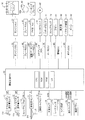
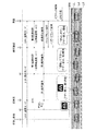
本発明の実施形態に係る車両制御装置は、図1に示したように、車両(以下において、他の車両と区別するために、「自車両」と称呼される場合がある。)に適用され、運転支援ECU10、エンジンECU30、ブレーキECU40、電動パーキングブレーキECU50、ステアリングECU60、メータECU70、警報ECU80、および、ボディECU90を備えている。
As shown in FIG. 1, the vehicle control device according to the embodiment of the present invention is applied to a vehicle (hereinafter, sometimes referred to as “own vehicle” in order to be distinguished from other vehicles). , A driving
これらのECUは、マイクロコンピュータを主要部として備える電気制御装置(Electric Control Unit)であり、図示しないCAN(Controller Area Network)を介して相互に情報を送信可能及び受信可能に接続されている。本明細書において、マイクロコンピュータは、CPU、ROM、RAM、不揮発性メモリ及びインターフェースI/F等を含む。CPUはROMに格納されたインストラクション(プログラム、ルーチン)を実行することにより各種機能を実現するようになっている。これらのECUは、幾つか又は全部が一つのECUに統合されてもよい。 These ECUs are electric control units (Electric Control Units) each including a microcomputer as a main part, and are connected to each other so as to be able to transmit and receive information via a CAN (Controller Area Network) (not shown). In this specification, the microcomputer includes a CPU, a ROM, a RAM, a nonvolatile memory, an interface I / F, and the like. The CPU implements various functions by executing instructions (programs, routines) stored in the ROM. Some or all of these ECUs may be integrated into one ECU.
運転支援ECU10は、以下に列挙するセンサ(スイッチを含む。)と接続されていて、それらのセンサの検出信号又は出力信号を受信するようになっている。なお、各センサは、運転支援ECU10以外のECUに接続されていてもよい。その場合、運転支援ECU10は、センサが接続されたECUからCANを介してそのセンサの検出信号又は出力信号を受信する。
The driving
アクセルペダル操作量センサ11は、自車両のアクセルペダル11aの操作量(アクセル開度)を検出し、アクセルペダル操作量APを表す信号を出力するようになっている。
ブレーキペダル操作量センサ12は、自車両のブレーキペダル12aの操作量を検出し、ブレーキペダル操作量BPを表す信号を出力するようになっている。
ストップランプスイッチ13は、ブレーキペダル12aが踏み込まれていないとき(操作されていないとき)にローレベル信号を出力し、ブレーキペダル12aが踏み込まれたとき(操作されているとき)にハイレベル信号を出力するようになっている。
The accelerator pedal
The brake pedal
The
操舵角センサ14は、自車両の操舵角を検出し、操舵角θを表す信号を出力するようになっている。
操舵トルクセンサ15は、操舵ハンドルSWの操作により自車両のステアリングシャフトUSに加わる操舵トルクを検出し、操舵トルクTraを表す信号を出力するようになっている。
車速センサ16は、自車両の走行速度(車速)を検出し、車速SPDを表す信号を出力するようになっている。
The
The
The
レーダセンサ17aは、自車両の前方の道路、及び、その道路に存在する立体物に関する情報を取得するようになっている。立体物は、例えば、歩行者、自転車及び自動車などの移動物、並びに、電柱、樹木及びガードレールなどの固定物を表す。以下、これらの立体物は「物標」と称呼される場合がある。
The
レーダセンサ17aは、何れも図示しない「レーダ送受信部と信号処理部」とを備えている。
レーダ送受信部は、ミリ波帯の電波(以下、「ミリ波」と称呼する。)を自車両の前方領域を含む自車両の周辺領域に放射し、放射範囲内に存在する物標によって反射されたミリ波(即ち、反射波)を受信する。
信号処理部は、送信したミリ波と受信した反射波との位相差、反射波の減衰レベル及びミリ波を送信してから反射波を受信するまでの時間等に基づいて、検出した各物標に対する、車間距離(縦距離)、相対速度、横距離、及び、相対横速度等を所定時間の経過毎に取得する。
The
The radar transmitter / receiver radiates millimeter wave radio waves (hereinafter referred to as “millimeter waves”) to the surrounding area of the host vehicle including the front area of the host vehicle, and is reflected by a target existing within the radiation range. A millimeter wave (that is, a reflected wave) is received.
The signal processing unit detects each target detected based on the phase difference between the transmitted millimeter wave and the received reflected wave, the attenuation level of the reflected wave, and the time from when the millimeter wave is transmitted until the reflected wave is received. The inter-vehicle distance (vertical distance), the relative speed, the lateral distance, the relative lateral speed, and the like are acquired every predetermined time.
カメラ装置17bは、何れも図示しない「ステレオカメラ及び画像処理部」を備えている。
ステレオカメラは、自車両前方の左側領域及び右側領域の風景を撮影して左右一対の画像データを取得する。
画像処理部は、ステレオカメラが撮影した左右一対の画像データに基づいて、物標の有無及び自車両と物標との相対関係などを演算して出力するようになっている。
The
The stereo camera captures a landscape of the left area and the right area in front of the host vehicle and acquires a pair of left and right image data.
The image processing unit calculates and outputs the presence / absence of the target and the relative relationship between the vehicle and the target based on a pair of left and right image data captured by the stereo camera.
なお、運転支援ECU10は、レーダセンサ17aによって得られた自車両と物標との相対関係と、カメラ装置17bによって得られた自車両と物標との相対関係と、を合成することにより、自車両と物標との相対関係(物標情報)を決定するようになっている。更に、運転支援ECU10は、カメラ装置17bが撮影した左右一対の画像データ(道路画像データ)に基づいて、道路の左及び右の白線などのレーンマーカー(以下、単に「白線」と称呼する。)を認識し、道路の形状(道路の曲がり方の程度を示す曲率半径)、及び、道路と自車両との位置関係等を取得するようになっている。加えて、運転支援ECU10は、カメラ装置17bが撮影した画像データに基づいて、路側壁が存在するか否かについての情報も取得できるようになっている。
The driving
操作スイッチ18は、運転者により操作されるスイッチである。運転者は、操作スイッチ18を操作することにより、車線維持制御(LKA:レーン・キーピング・アシスト制御)を実行するか否かを選択することができる。また、運転者は、操作スイッチ18を操作することにより、車線逸脱防止制御(LDA:レーン・デパーチャー・アラート制御)を実行するか否かを選択することができる。更に、運転者は、操作スイッチ18を操作することにより、追従車間距離制御(ACC:アダプティブ・クルーズ・コントロール)を実行するか否かを選択することができる。
The
確認ボタン19は、運転者により操作可能な位置に配設されていて、操作されていない場合にはローレベル信号を出力し、押動操作されるとハイレベル信号を出力するようになっている。
The
運転支援ECU10は、車線維持制御、車線逸脱防止制御、及び、追従車間距離制御を実行できるようになっている。更に、運転支援ECU10は、後述するように、運転者が車両を運転する能力を失っている異常状態にあるか否かを判定するとともに、運転者が異常状態にあると判定した場合に適切な処理を行うための各種制御を行うようになっている。
The driving
エンジンECU30は、エンジンアクチュエータ31に接続されている。エンジンアクチュエータ31は内燃機関32の運転状態を変更するためのアクチュエータである。本例において、内燃機関32はガソリン燃料噴射・火花点火式・多気筒エンジンであり、吸入空気量を調整するためのスロットル弁を備えている。エンジンアクチュエータ31は、少なくとも、スロットル弁の開度を変更するスロットル弁アクチュエータを含む。エンジンECU30は、エンジンアクチュエータ31を駆動することによって、内燃機関32が発生するトルクを変更することができる。内燃機関32が発生するトルクは図示しない変速機を介して図示しない駆動輪に伝達されるようになっている。従って、エンジンECU30は、エンジンアクチュエータ31を制御することによって、自車両の駆動力を制御し加速状態(加速度)を変更することができる。
The
ブレーキECU40は、ブレーキアクチュエータ41に接続されている。ブレーキアクチュエータ41は、ブレーキペダルの踏力によって作動油を加圧する図示しないマスタシリンダと、左右前後輪に設けられる摩擦ブレーキ機構42との間の油圧回路に設けられる。摩擦ブレーキ機構42は、車輪に固定されるブレーキディスク42aと、車体に固定されるブレーキキャリパ42bとを備える。ブレーキアクチュエータ41は、ブレーキECU40からの指示に応じてブレーキキャリパ42bに内蔵されたホイールシリンダに供給する油圧を調整し、その油圧によりホイールシリンダを作動させることによりブレーキパッドをブレーキディスク42aに押し付けて摩擦制動力を発生させる。従って、ブレーキECU40は、ブレーキアクチュエータ41を制御することによって、自車両の制動力を制御することができる。
The
電動パーキングブレーキECU(以下、「EPB・ECU」と称呼される場合がある。)50は、パーキングブレーキアクチュエータ(以下、「PKBアクチュエータ」と称呼される場合がある。)51に接続されている。PKBアクチュエータ51は、ブレーキパッドをブレーキディスク42aに押し付けるか、ドラムブレーキを備えている場合には車輪とともに回転するドラムにシューを押し付けるためのアクチュエータである。従って、EPB・ECU50は、PKBアクチュエータ51を用いてパーキングブレーキ力を車輪に加え、自車両を停止状態に維持することができる。
An electric parking brake ECU (hereinafter sometimes referred to as “EPB • ECU”) 50 is connected to a parking brake actuator (hereinafter sometimes referred to as “PKB actuator”) 51. The
ステアリングECU60は、周知の電動パワーステアリングシステムの制御装置であって、モータドライバ61に接続されている。モータドライバ61は、転舵用モータ62に接続されている。転舵用モータ62は、図示しない車両の「操舵ハンドル、操舵ハンドルに連結されたステアリングシャフト及び操舵用ギア機構等を含むステアリング機構」に組み込まれている。転舵用モータ62は、モータドライバ61から供給される電力によってトルクを発生し、このトルクによって操舵アシストトルクを加えたり、左右の操舵輪を転舵したりすることができる。
The steering
メータECU70は、図示しないデジタル表示式メータに接続されるとともに、ハザードランプ71及びストップランプ72にも接続されている。メータECU70は、運転支援ECU10からの指示に応じて、ハザードランプ71を点滅させることができ、且つ、ストップランプ72を点灯させることができる。
The
警報ECU80は、ブザー81及び表示器82に接続されている。警報ECU80は、運転支援ECU10からの指示に応じてブザー81を鳴動させて運転者への注意喚起を行うことができ、且つ、表示器82に注意喚起用のマーク(例えば、ウォーニングランプ)を点灯させたり、警告メッセージを表示したり、運転支援制御の作動状況を表示したりすることができる。
The
ボディECU90は、ドアロック装置91、および、ホーン92に接続されている。ボディECU90は、運転支援ECU10からの指示に応じて、ドアロック装置91の解除を行うことができる。また、ボディECU90は、運転支援ECU10からの指示に応じて、ホーン92を鳴動させることができる。
The
<運転支援ECU10の行う制御処理>
次に、運転支援ECU10の行う制御処理について説明する。運転支援ECU10は、車線維持制御(LKA)及び追従車間距離制御(ACC)の両方が実行されている場合に、後述する異常時運転支援制御ルーチン(図5)を実施する。そこで、先ず、車線維持制御及び追従車間距離制御から説明する。また、後述する変形例において、運転支援ECU10は、異常時運転支援制御ルーチンの実施中に、車線逸脱防止制御(LDA)を開始する場合もあるため、この車線逸脱防止制御についてもあわせて説明する。
<Control processing performed by the driving
Next, a control process performed by the driving
<車線維持制御(LKA)>
車線維持制御(以下、LKAと呼ぶ)は、自車両の位置が「その自車両が走行しているレーン(走行車線)」内の目標走行ライン付近に維持されるように、操舵トルクをステアリング機構に付与して運転者の操舵操作を支援する制御である。LKA自体は周知である(例えば、特開2008−195402号公報、特開2009−190464号公報、特開2010−6279号公報、及び、特許第4349210号明細書、等を参照。)。従って、以下、簡単に説明する。
<Lane maintenance control (LKA)>
Lane maintenance control (hereinafter referred to as LKA) is a steering mechanism that controls the steering torque so that the position of the host vehicle is maintained near the target travel line in the “lane (travel lane) in which the host vehicle is traveling”. This control is provided to assist the steering operation of the driver. LKA itself is well known (see, for example, Japanese Patent Application Laid-Open Nos. 2008-195402, 2009-190464, 2010-6279, and Japanese Patent No. 4349210). Accordingly, a brief description will be given below.
運転支援ECU10は、操作スイッチ18の操作によってLKAが要求されている場合、LKAを実行する。より具体的に述べると、図2に示したように、運転支援ECU10は、LKAが要求されている場合に、カメラ装置17bから送信された画像データに基づいて自車両が走行している車線の「左白線LL及び右白線LR」を認識(取得)し、それらの一対の白線の中央位置を目標走行ラインLdとして決定する。更に、運転支援ECU10は、目標走行ラインLdのカーブ半径(曲率半径)Rと、左白線LLと右白線LRとで区画される走行車線における自車両の位置及び向きと、を演算する。そして、運転支援ECU10は、図3に示すように、自車両Cの前端中央位置と目標走行ラインLdとのあいだの道路幅方向の距離Dc(以下、「センター距離Dc」と称呼する。)と、目標走行ラインLdの方向と自車両Cの進行方向とのずれ角θy(以下、「ヨー角θy」と称呼する。)とを演算する。
When the LKA is requested by the operation of the
更に、運転支援ECU10は、センター距離Dcとヨー角θyと道路曲率ν(=1/曲率半径R)とに基づいて、下記の(1)式により、目標舵角θLKA*を所定の演算周期にて演算する。(1)式において、K1、K2及びK3は制御ゲインである。目標舵角θLKA*は、自車両が目標走行ラインLdに沿って走行できるように設定される舵角である。
θLKA*=K1×ν+K2×θy+K3×Dc …(1)
Further, the driving
θLKA * = K1 × ν + K2 × θy + K3 × Dc (1)
運転支援ECU10は、この目標舵角θLKA*を表す指令信号をステアリングECU60に出力する。ステアリングECU60は、舵角が目標舵角θLKA*に追従するように転舵用モータ62を駆動制御する。この場合、運転支援ECU10は、目標舵角θLKA*と実舵角とに基づいて、目標舵角θLKA*を得るための目標トルクを所定の演算周期にて演算する。例えば、運転支援ECU10は、目標舵角θLKA*と実舵角との偏差と、目標トルクとの関係を規定したルックアップテーブルを予め記憶しており、このテーブルを参照することにより目標トルクを演算する。そして、運転支援ECU10は、ステアリングECU60を用いて転舵用モータ62で目標トルクを発生するように転舵用モータ62を駆動制御する。尚、実舵角は、操舵角センサ14によって検出される操舵角θを用いてもよいし、操舵輪の舵角を直接検出するセンサの検出値を用いてもよい。
The driving
尚、LKAで用いる制御量は、この例では、目標舵角θLKA*としているが、それに代えて、自車両の目標ヨーレート、あるいは、目標横加速度としてもよい。つまり、式(1)の左辺を目標ヨーレート、あるいは、目標横加速度としてもよい。この場合、例えば、運転支援ECU10は、図示しないヨーレートセンサ、あるいは、横加速度センサの検出信号を入力し、目標ヨーレートと実ヨーレート(ヨーレートセンサの検出値)との偏差、あるいは、目標横加速度と実横加速度(横加速度センサの検出値)との偏差を演算する。そして、運転支援ECU10は、こうした偏差と目標トルクとの関係を規定したルックアップテーブルを参照して、目標トルクを演算する。
The control amount used in the LKA is the target rudder angle θLKA * in this example, but may instead be the target yaw rate of the host vehicle or the target lateral acceleration. That is, the left side of equation (1) may be the target yaw rate or the target lateral acceleration. In this case, for example, the driving
尚、LKAは、あくまでも自車両の走行位置が目標走行ラインLdに沿って走行するように運転者の運転を支援するものである。従って、LKAが実施されている場合であっても、手放し運転が許容されるわけではなく、運転者は、操舵ハンドルSWを握っている必要がある。以上が、LKAの概要である。 The LKA assists the driving of the driver so that the traveling position of the vehicle travels along the target traveling line Ld. Therefore, even if LKA is being implemented, hand-release operation is not permitted, and the driver needs to hold the steering wheel SW. The above is the outline of LKA.
このLKAを実施する運転支援ECU10の機能部が、本発明の車線維持支援手段に相当する。
The functional part of the driving
<車線逸脱防止制御(LDA)>
車線逸脱防止制御(以下、LDAと呼ぶ)は、自車両の位置が「その自車両が走行しているレーン(走行車線)」の外に逸脱しないように、操舵トルクをステアリング機構に付与して運転者の操舵操作を支援する制御である。また、LDAが実行される場合には、運転者に対してブザー81あるいは表示器82によって警告が行われる。LDA自体は周知である。従って、以下、簡単に説明する。
<Lane departure prevention control (LDA)>
Lane departure prevention control (hereinafter referred to as LDA) applies steering torque to the steering mechanism so that the position of the host vehicle does not deviate outside the “lane in which the host vehicle is traveling (running lane)”. This control assists the driver's steering operation. Further, when the LDA is executed, a warning is given to the driver by the
運転支援ECU10は、操作スイッチ18の操作によってLDAが要求されている場合、LDAを実行する。より具体的に述べると、運転支援ECU10は、LDAが要求されている場合に、LKAの実行時と同様に、図2に示すように、カメラ装置17bから送信された画像データに基づいて自車両が走行している車線の「左白線LL及び右白線LR」を認識(取得)し、それらの一対の白線の中央位置である中央ラインLdのカーブ半径Rを演算する。また、運転支援ECU10は、図4に示すように、中央ラインLdの方向と自車両Cの向いている方向とのずれ角θy(以下、ヨー角θyと呼ぶ)とを演算する。更に、運転支援ECU10は、自車両Cの右前輪と右白線LRとの間、および、左前輪と左白線LLとの間のそれぞれの道路幅方向の距離Ds(サイド距離Dsと呼ぶ)を演算する。図4は、右前輪と右白線LRとの間のサイド距離Dsのみを示している。この場合、サイド距離Dsは、左右2つ存在するが、LDAの制御量の演算にあたっては、自車両が車線から逸脱すると推定される方向、つまり、ヨー角θyによって示されている方向のサイド距離Dsを用いればよい。
When the LDA is requested by operating the
運転支援ECU10は、下記(2)式により、目標舵角θLDA*を所定の演算周期にて演算する。目標舵角θLDA*は、自車両が白線の外側に逸脱しないように設定される舵角である。
θLDA*=K4×ν+K5×θy+K6×Ds’ …(2)
The driving
θLDA * = K4 × ν + K5 × θy + K6 × Ds ′ (2)
ここで、K4、K5、および、K6は、それぞれ制御ゲインである。また、νは道路曲率(=1/R)である。また、Ds’は、サイド距離Dsに対応して設定され、前輪が逸脱回避の対象となる白線よりも内側(道路中央側)に位置する場合には、その前輪が白線よりも内側に位置するほど(Dsが大きいほど)小さな値に設定され、前輪が逸脱回避の対象となる白線よりも外側に位置する場合には、その前輪が白線から外方向に離れるほど大きな値に設定される。 Here, K4, K5, and K6 are control gains, respectively. Further, ν is a road curvature (= 1 / R). Further, Ds ′ is set corresponding to the side distance Ds, and when the front wheel is located on the inner side (the road center side) of the white line to be avoided, the front wheel is located on the inner side of the white line. If the front wheel is located outside the white line that is to be avoided, the larger the value is set, the farther the front wheel is away from the white line.
運転支援ECU10は、この目標舵角θLDA*を表す指令信号をステアリングECU60に出力する。ステアリングECU60は、舵角が目標舵角θLDA*に追従するように転舵用モータ62を駆動制御する。この場合、運転支援ECU10は、LKAの実行時と同様に、目標舵角θLDA*と実舵角とに基づいて、目標操舵トルクを所定の演算周期にて演算し、ステアリングECU60を用いて転舵用モータ62で目標トルクを発生するように転舵用モータ62を駆動制御する。
The driving
尚、LDAで用いる制御量は、この例では、目標舵角θLDA*としているが、それに代えて、目標ヨーレート、あるいは、目標横加速度としてもよい。つまり、式(2)の左辺を自車両の目標ヨーレート、あるいは、目標横加速度としてもよい。この場合、例えば、運転支援ECU10は、図示しないヨーレートセンサ、あるいは、横加速度センサの検出信号を入力し、目標ヨーレートと実ヨーレート(ヨーレートセンサの検出値)との偏差、あるいは、目標横加速度と実横加速度との偏差を演算する。そして、運転支援ECU10は、こうした偏差と目標トルクとの関係を規定したルックアップテーブルを参照して、転舵用モータ62の発生させる目標トルクを演算する。以上が、LDAの概要である。
The control amount used in the LDA is the target rudder angle θLDA * in this example, but it may be the target yaw rate or the target lateral acceleration instead. That is, the left side of equation (2) may be the target yaw rate of the host vehicle or the target lateral acceleration. In this case, for example, the driving
このLDAを実施する運転支援ECU10の機能部が、本発明の車線逸脱防止手段に相当する。
The functional part of the driving
<追従車間距離制御(ACC)>
追従車間距離制御(以下、ACCと呼ぶ)は、物標情報に基づいて、自車両の直前を走行している先行車と自車両との車間距離を所定の距離に維持しながら、自車両を先行車に追従させる制御である。ACC自体は周知である(例えば、特開2014−148293号公報、特開2006−315491号公報、特許第4172434号明細書、及び、特許第4929777号明細書等を参照。)。従って、以下、簡単に説明する。
<Following inter-vehicle distance control (ACC)>
Following inter-vehicle distance control (hereinafter referred to as ACC) is based on the target information, while maintaining the inter-vehicle distance between the preceding vehicle and the own vehicle that are traveling immediately before the own vehicle at a predetermined distance. This control is to follow the preceding vehicle. ACC itself is well known (see, for example, Japanese Patent Application Laid-Open No. 2014-148293, Japanese Patent Application Laid-Open No. 2006-315491, Japanese Patent No. 4172434, and Japanese Patent No. 4929777). Accordingly, a brief description will be given below.
運転支援ECU10は、操作スイッチ18の操作によってACCが要求されている場合、ACCを実行する。
The driving
より具体的に述べると、運転支援ECU10は、ACCが要求されている場合、レーダセンサ17aおよびカメラ装置17bにより取得した物標情報に基づいて追従対象車両を選択する。例えば、運転支援ECU10は、検出した物標(n)の横距離Dfy(n)と車間距離Dfx(n)とから特定される物標(n)の相対位置が、車間距離が長くなるほど横距離が短くなるように予め定められた追従対象車両エリア内に存在するか否かを判定する。そして、その物標の相対位置が追従対象車両エリア内に所定時間以上に渡って存在する場合、その物標(n)を追従対象車両として選択する。
More specifically, when the ACC is requested, the driving
更に、運転支援ECU10は、目標加速度Gtgtを下記(3)式及び(4)式の何れかに従って算出する。(3)式及び(4)式において、Vfx(a)は追従対象車両(a)の相対速度であり、k1及びk2は所定の正のゲイン(係数)であり、ΔD1は「追従対象車両(a)の車間距離Dfx(a)から目標車間距離Dtgt」を減じることにより得られる車間偏差(=Dfx(a)−Dtgt)である。なお、目標車間距離Dtgtは、運転者により操作スイッチ18を用いて設定される目標車間時間Ttgtに自車両の車速SPDを乗じることにより算出される(即ち、Dtgt=Ttgt・SPD)。
Furthermore, the driving
運転支援ECU10は、値(k1・ΔD1+k2・Vfx(a))が正又は「0」の場合に下記(3)式を使用して目標加速度Gtgtを決定する。ka1は、加速用の正のゲイン(係数)であり、「1」以下の値に設定されている。
運転支援ECU10は、値(k1・ΔD1+k2・Vfx(a))が負の場合に下記(4)式を使用して目標加速度Gtgtを決定する。kd1は、減速用のゲイン(係数)であり、本例においては「1」に設定されている。
Gtgt(加速用)=ka1・(k1・ΔD1+k2・Vfx(a)) …(3)
Gtgt(減速用)=kd1・(k1・ΔD1+k2・Vfx(a)) …(4)
When the value (k1 · ΔD1 + k2 · Vfx (a)) is positive or “0”, the driving
When the value (k1 · ΔD1 + k2 · Vfx (a)) is negative, the driving
Gtgt (for acceleration) = ka1 · (k1 · ΔD1 + k2 · Vfx (a)) (3)
Gtgt (for deceleration) = kd1 · (k1 · ΔD1 + k2 · Vfx (a)) (4)
なお、追従対象車両エリアに物標が存在しない場合、運転支援ECU10は、自車両の車速SPDが「目標車間時間Ttgtに応じて設定される目標速度」に一致するように、目標速度と車速SPDに基づいて目標加速度Gtgtを決定する。
When the target does not exist in the tracking target vehicle area, the driving
運転支援ECU10は、自車両の加速度が目標加速度Gtgtに一致するように、エンジンECU30を用いてエンジンアクチュエータ31を制御するとともに、必要に応じてブレーキECU40を用いてブレーキアクチュエータ41を制御する。以上が、ACCの概要である。
The driving
<異常時運転支援制御ルーチン>
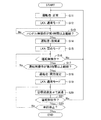
次に、運転支援ECU10の行う異常時運転支援制御処理について説明する。図5は、運転支援ECU10の実施する異常時運転支援制御ルーチンを表す。運転支援ECU10は、LKAおよびACCの両方を実施しているときに、それらと並行して、異常時運転支援制御ルーチンを実施する。
<Driving control routine during abnormal conditions>
Next, the abnormality time driving support control process performed by the driving
異常時運転支援制御ルーチンが起動すると、運転支援ECU10は、ステップS11において、運転者の状態を「正常」に設定する。この異常時運転支援制御ルーチンにおいては、運転者の状態に従って、その処理を決定するが、起動時においては運転者の状態が設定されていない。そこで、このステップS11では、初期設定を兼ねて、運転者の状態が「正常」に設定される。
When the abnormal-time driving support control routine is activated, the driving
続いて、運転支援ECU10は、ステップS12において、LKAの制御モードを「通常モード」に設定する。LKAは、その制御モードが「通常モード」と「弱めモード」とに分かれており、その一方のモードが選択されて実行される。「通常モード」は、自車両が目標走行ラインに沿って適切に走行できるように舵角が制御されるモードであり、上述した式(1)にて制御量が設定される。一方、「弱めモード」は、「通常モード」に比べて、自車両が目標走行ラインに沿って走行しにくくなるように舵角が制御されるモードである。LKAは、「弱めモード」が設定されない限り、「通常モード」に設定される。このLKAにおける2つの制御モードは、運転者の好みによって設定されるものでは無く、この異常時運転支援制御ルーチンによって設定される。
Subsequently, in step S12, the driving
運転支援ECU10は、異常時運転支援制御ルーチンと並行してLKAを実施している。従って、ステップS12は、異常時運転支援制御ルーチンと並行して実施されているLKAの制御モードを「通常モード」に設定する。従って、自車両は目標走行ラインに沿って走行するように運転者の操舵操作が支援される。
The driving
続いて、運転支援ECU10は、ステップS13において、操舵ハンドルSWが操作されていない手放し時間が第1時間以上継続したか否について判定する。つまり、運転支援ECU10は、操舵ハンドルSWが操作されていない手放し継続時間を計測し、手放し継続時間が第1時間以上であるか否かについて判定する。例えば、操舵ハンドルSWが操作されていない状態は、操舵トルクセンサによって検出された操舵トルクTraが「0」となっている状態として検出することができる。従って、ステップS13においては、操舵トルクTraが「0」となっている継続時間が第1時間以上であるか否かについて判定される。
Subsequently, in step S13, the driving
手放し継続時間の計測は、例えば、所定の演算周期で操舵トルクTraが「0」となっているか否かを判定し、Tra=0が検出されるたびにタイマ値をインクリメントし、Tra≠0が検出されるたびにそのタイマ値をゼロクリアするようにすればよい。この場合、タイマ値が第1時間以上に到達したときに、ステップS13の判定が「Yes」となる。 For example, it is determined whether or not the steering torque Tra is “0” in a predetermined calculation cycle, the timer value is incremented every time Tra = 0 is detected, and Tra ≠ 0 is measured. The timer value may be cleared to zero each time it is detected. In this case, when the timer value reaches the first time or more, the determination in step S13 is “Yes”.
運転支援ECU10は、手放し継続時間が第1時間到達するまで、ステップS13の判定を繰り返し実施する。こうした処理が繰り返され、手放し継続時間が第1時間に到達すると(S13:Yes)、運転支援ECU10は、ステップS14において、運転者が異常状態にあると仮に判定する。後述するように、運転者が異常状態にあるとの判定は、ステップS14の判定を含めて、2回に分けて行われる。最初の判定が、このステップS14における判定である。この判定を仮の判定と呼び、このときの運転者の状態を「仮異常」と呼ぶ。
The driving
運転者が異常状態にあると仮に判定される場合、運転者が、実際に車両を運転する能力を失っている異常状態である場合と、車両を運転する能力を有しているにもかかわらずハンドル操作を怠っている(手放し運転をしている)場合とが含まれている。 If it is temporarily determined that the driver is in an abnormal state, the driver is in an abnormal state in which he / she actually loses the ability to drive the vehicle, even though he has the ability to drive the vehicle. The case where the steering wheel operation is neglected (the operation is letting go) is included.
そこで、運転支援ECU10は、後者のハンドル操作を怠っている運転者に対してハンドル操作を促すために、ステップS15において、LKAの制御モードを「通常モード」から「弱めモード」に切り替える(「通常モード」→「弱めモード」)。運転支援ECU10は、LKAの制御モードを「弱めモード」に設定した場合、上記式(1)における制御ゲインK2,制御ゲインK3を、「通常モード」で使用する値に比べて小さな値に変更する。つまり、ヨー角θyの大きさに比例したヨー角比例項の制御ゲインK2と、センター距離Dcの大きさに比例したセンター距離比例項の制御ゲインK3とを、「通常モード」で使用する値に比べて小さな値に変更する。
Therefore, the driving
例えば、制御ゲインK2,制御ゲインK3について、「通常モード」における値を通常制御ゲインK2a,通常制御ゲインK3aと表し、「弱めモード」における値を弱め制御ゲインK2b,弱め制御ゲインK3bと表した場合、弱め制御ゲインK2b,K3bは、例えば、以下のように表される。
K2b=0.1×K2a
K3b=0.1×K3a
この例では、弱め制御ゲインK2b,K3bは、それぞれ、通常制御ゲインK2a,K3aの1/10に設定されるが、弱め度合は任意に設定できるものである。
For example, regarding the control gain K2 and the control gain K3, values in the “normal mode” are represented as normal control gain K2a and normal control gain K3a, and values in the “weak mode” are represented as weak control gain K2b and weak control gain K3b. The weakening control gains K2b and K3b are expressed as follows, for example.
K2b = 0.1 × K2a
K3b = 0.1 × K3a
In this example, the weakening control gains K2b and K3b are set to 1/10 of the normal control gains K2a and K3a, respectively, but the degree of weakening can be arbitrarily set.
従って、LKAの制御モードが「弱めモード」に設定されると、「通常モード」に比べて、自車両が目標走行ラインLdに沿って走行しにくくなり、横方向(道路幅方向)にふらつくようになる。この場合、道路曲率ν(=1/曲率半径R)の大きさに比例した曲率比例項の制御ゲインK1については、変更されない。この理由は、制御ゲインK1を小さくすると、カーブしている道路を走行している場合に、自車両が走行レーンの左右白線の外に逸脱するおそれがあるからである。従って、制御ゲインK2,制御ゲインK3についてのみ低減することにより、自車両を走行レーン内の外に逸脱させないように走行レーン内で適切にふらつかせることができる。 Therefore, when the LKA control mode is set to the “weak mode”, the host vehicle is less likely to travel along the target travel line Ld as compared to the “normal mode”, and may fluctuate in the lateral direction (road width direction). become. In this case, the control gain K1 of the curvature proportional term proportional to the magnitude of the road curvature ν (= 1 / curvature radius R) is not changed. This is because if the control gain K1 is decreased, the host vehicle may deviate from the left and right white lines of the travel lane when traveling on a curved road. Therefore, by reducing only the control gain K2 and the control gain K3, the host vehicle can be appropriately swung within the travel lane so as not to deviate outside the travel lane.
このように自車両の走行状態が変化すると、運転者にとって所望となる走行ラインを自車両が走行しなくなる。このため、運転能力を失っていない運転者に対してハンドル操作が促される。これにより、ハンドル操作を怠っていた運転者は、ハンドル操作を開始するとともに、LKAを過信しなくなる。また、例えば、自車両をふらつかせることによって、居眠りしていた運転者を目覚めさせることができる場合もある。 When the traveling state of the host vehicle changes in this manner, the host vehicle does not travel on the travel line desired by the driver. For this reason, steering operation is urged to the driver who has not lost driving ability. As a result, the driver who has neglected the steering wheel operation starts the steering wheel operation and does not overtrust LKA. In addition, for example, the driver who has fallen asleep can be awakened by wobbling the own vehicle.
従って、運転能力を失っていない運転者であれば、ハンドル操作に限らず、自車両の走行状態の変化によって何らかの反応を示す。例えば、ブレーキペダル操作、あるいは、アクセルペダル操作などの運転者の意識的な運転操作が開始されることもある。あるいは、運転者の意識的な姿勢の変化などが現れることもある。従って、こうした運転者の反応の有無に基づいて、運転者が車両を運転する能力を失っている異常状態であるのか、車両を運転する能力を有しているにもかかわらずハンドル操作を怠っている状態であったのかについて判別することができる。 Therefore, a driver who does not lose driving ability shows some reaction not only by the steering wheel operation but also by a change in the traveling state of the own vehicle. For example, a driver's conscious driving operation such as a brake pedal operation or an accelerator pedal operation may be started. Or, the driver's conscious attitude may change. Therefore, based on the presence / absence of the driver's reaction, the driver has lost the ability to drive the vehicle, or it is an abnormal state that neglects the steering wheel operation despite having the ability to drive the vehicle. It is possible to determine whether it was in a state.
運転支援ECU10は、LKAの制御モードを「弱めモード」に設定すると、続く、ステップS16において、運転者が車両を運転するための操作を行わない状態(運転無操作状態)であるか否かについて判定する。この運転無操作状態とは、運転者の操作(運転操作子への入力)によって変化する「アクセルペダル操作量AP、ブレーキペダル操作量BP、操舵トルクTra及びストップランプスイッチ13の信号レベル」の一つ以上の組み合わせからなるパラメータの何れもが変化しない状態である。
When the driving
運転支援ECU10は、運転無操作状態である場合(S16:Yes)には、続くステップS17において、運転無操作状態が予め設定した閾値である第2時間以上継続したか否かについて判定する。このステップS17で用いられる運転無操作状態の継続時間は、仮の判定がなされてからの継続時間でもよいし、あるいは、ステップS13で計測された手放し継続時間を引き継いだ時間であってもよい。後者の場合には、第2時間は、第1時間よりも長い時間に設定される。
If the driving
運転無操作状態の継続時間が第2時間未満である場合(S17:No)、運転支援ECU10は、その処理をステップS16に戻す。このようにして、運転支援ECU10は、所定の演算周期でステップS16,S17の処理を繰り返し実施する。この状況においては、運転支援ECU10が判定している運転者の状態は、「仮異常」に維持されている。
When the duration of the no-operation state is less than the second time (S17: No), the driving
運転無操作状態の継続時間が第2時間に到達する前に、運転操作が検出された場合(S16:No)、運転支援ECU10は、その処理をステップS11に戻す。従って、運転者が異常状態にあるとの仮の判定が取り消され、運転者の状態は、「正常」に設定される。また、LKAの制御モードが「通常モード」に戻される(「弱めモード」→「通常モード」)。
If the driving operation is detected before the duration time of the driving non-operation state reaches the second time (S16: No), the driving
例えば、ハンドル操作を怠って手放し運転をしていた運転者が、自車両の走行状態の変化によってハンドル操作を再開した場合には、ステップS16において「No」と判定されて、運転者が異常状態にあるとの仮の判定が取り消される。 For example, if the driver who has neglected the steering wheel operation and drove the driving operation again due to a change in the traveling state of the host vehicle, it is determined as “No” in step S16, and the driver is in an abnormal state. The tentative determination that it is in is canceled.
一方、自車両の走行状態の変化にも関わらず、運転無操作状態の継続時間が第2時間に達した場合(S17:Yes)、運転支援ECU10は、その処理をステップS18に進めて、運転者が異常状態にあるとの判定を確定させる。これにより、運転支援ECU10が判定している運転者の状態は、「仮異常」から「異常」に切り替わる。続いて、運転支援ECU10は、その処理をステップS19に進めて、LKAの制御モードを「通常モード」に切り替える(「弱めモード」→「通常モード」)。これにより、自車両を目標走行ラインLdに沿って適性に走行させることができる。
On the other hand, when the duration of the no-operation state has reached the second time despite the change in the traveling state of the host vehicle (S17: Yes), the driving
続いて、運転支援ECU10は、ステップS20において、ACCを中止して、自車両を予め設定された一定の目標減速度αで減速させる。この場合、運転支援ECU10は、車速センサ16からの信号に基づいて取得される車速SPDの単位時間あたりの変化量から自車両の加速度を求め、その加速度を目標減速度αと一致させるための指令信号をエンジンECU30及びブレーキECU40に出力する。これにより、自車両を一定の目標減速度αにて減速させることができる。従って、LKAと並行して減速制御が実施される。
Subsequently, in step S20, the driving
続いて、運転支援ECU10は、ステップS21において、運転者が車両を運転するための操作を行わない運転無操作状態であるか否かについて判定する。運転支援ECU10は、運転無操作状態である場合には、ステップS22において、車速SPDに基づいて、自車両が停止したか否かについて判定する。運転支援ECU10は、自車両が停止していない場合、その処理をステップS20に戻して、自車両を目標減速度αで減速させる制御処理である減速制御を継続する。
Subsequently, in step S21, the driving
自車両の減速途中において、運転操作が検出された場合(S21:No)、運転支援ECU10は、その処理をステップS11に戻す。従って、運転者が異常状態にあると確定された判定が取り消され、運転者の状態は、「正常」に設定される。また、LKAが「通常モード」に設定され、減速制御が中止される。
If a driving operation is detected during deceleration of the host vehicle (S21: No), the driving
運転支援ECU10は、運転操作が検出されないまま減速制御によって自車両が停止すると(S22:Yes)、本ルーチンを終了する。
The driving
以上説明した本実施形態の車両制御装置によれば、LKAの実行中に、運転者の手放し状態が第1時間継続されると、運転者が異常状態にあるとの仮の判定がなされて、LKAの制御モードが「弱めモード」に設定される。これにより、自車両を車線内でふらつかせることができ、これに伴って、運転者にハンドル操作が促される。従って、ハンドル操作を怠っていた運転者は、ハンドル操作を開始するとともに、LKAを過信しなくなる。こうして運転操作が開始された場合には、運転者が異常状態にあるとの仮の判定が取り消される。 According to the vehicle control device of the present embodiment described above, if the driver's release state is continued for the first time during execution of the LKA, a temporary determination that the driver is in an abnormal state is made. The control mode of LKA is set to “weak mode”. As a result, the host vehicle can be swung within the lane, and accordingly, the driver is prompted to operate the steering wheel. Accordingly, the driver who has neglected the steering wheel operation starts the steering wheel operation and does not overtrust LKA. When the driving operation is thus started, the provisional determination that the driver is in an abnormal state is cancelled.
一方、LKAを「弱めモード」に設定しても運転無操作状態が第2時間以上継続した場合には、運転者が異常状態にあるとの判定が確定する。従って、運転者が異常状態にあるとする判定精度が高くなった段階で、異常判定が確定し、この異常判定の確定によって、異常時運転制御が開始される。異常時運転制御の一つが、自車両を一定の目標減速度αにて減速させる減速制御であり、もう一つが、「通常モード」で実施されるLKAである。こうして、自車両を安全に停止させることができる。 On the other hand, if the no-operation state continues for the second time or more even if LKA is set to “weak mode”, the determination that the driver is in an abnormal state is confirmed. Therefore, when the determination accuracy that the driver is in an abnormal state becomes high, the abnormality determination is confirmed, and the abnormality-time operation control is started by the confirmation of the abnormality determination. One of the abnormal-time operation controls is a deceleration control that decelerates the host vehicle at a constant target deceleration rate α, and the other is an LKA that is performed in the “normal mode”. Thus, the host vehicle can be stopped safely.
<各種の変形例>
尚、ステップS16およびステップS21における判定に関して、本実施形態では、運転無操作状態であるか否かについて判定しているが、ここでは、運転者が運転能力を失っている状態であるか否かを判定することができる異常判定処理であればよく、他の異常判定方法を採用することができる。
<Various modifications>
In addition, regarding this determination in step S16 and step S21, in the present embodiment, it is determined whether or not there is no driving operation state, but here, whether or not the driver has lost driving ability. Any abnormality determination process that can determine whether or not other abnormality determination methods can be employed.
例えば、運転者の異常判定方法の別の例として、特開2013−152700号公報等に開示されている所謂「ドライバモニタ技術」を利用してもよい。より具体的に述べると、車室内の部材(例えば、ステアリングホイール及びピラー等)に運転者を撮影するカメラを設け、運転支援ECU10は、カメラの撮影画像を用いて運転者の視線の方向又は顔の向きを監視する。運転支援ECU10は、運転者の視線の方向又は顔の向きが車両の通常の運転中には長時間向くことがない方向に所定時間以上継続して向いている場合、運転者が異常状態にあると判定する。
For example, as another example of a driver abnormality determination method, a so-called “driver monitor technology” disclosed in JP 2013-152700 A may be used. More specifically, a camera for photographing the driver is provided on a vehicle interior member (for example, a steering wheel and a pillar), and the driving
運転者の異常判定方法の別の例として、確認ボタン19を利用してもよい。より具体的に述べると、運転支援ECU10は、設定確認時間T1の経過毎に確認ボタン19の操作を表示及び/又は音声によって催促し、確認ボタン19の操作がない状態が上記設定確認時間T1よりも長い時間である設定無応答時間T2以上に渡って継続したとき、運転者が異常状態にあると判定する。運転者の異常判定については、こうした方法以外にも、任意の方法を採用することができる。
As another example of the driver abnormality determination method, the
尚、後述する他の実施形態(第2〜第4実施形態)においても、運転無操作の判定に代えて、上記の運転者の異常判定方法等を採用することができる。 In other embodiments (second to fourth embodiments) to be described later, the above-described driver abnormality determination method and the like can be adopted instead of the determination of no driving operation.
<第2実施形態>
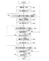
次に、第2実施形態の車両制御装置について説明する。第2実施形態の車両制御装置は、運転支援ECU10が、上述した異常時運転支援制御ルーチン(図5)に代えて、図6に示す異常時運転支援制御ルーチンを実施する点においてのみ、上述した実施形態と相違する。以下、上述した実施形態を第1実施形態と呼ぶ。
Second Embodiment
Next, the vehicle control apparatus of 2nd Embodiment is demonstrated. The vehicle control device of the second embodiment is described above only in that the driving
第2実施形態では、運転者が異常状態にあるとの仮の判定が行われた段階から自車両を減速させる点で第1実施形態と相違している。以下、第2実施形態における異常時運転支援制御ルーチン(図6)について説明する。第1実施形態と同一の処理については、図面に共通のステップ符号を付して、その説明を省略、あるいは、簡単な説明に留める。第2実施形態における異常時運転支援制御ルーチンが実施される条件は、第1実施形態と同様である。 The second embodiment is different from the first embodiment in that the host vehicle is decelerated from the stage when the provisional determination that the driver is in an abnormal state is performed. Hereinafter, the abnormal-time driving support control routine (FIG. 6) in the second embodiment will be described. About the process same as 1st Embodiment, a common step code | symbol is attached | subjected to drawing, the description is abbreviate | omitted or it keeps only simple description. The conditions under which the abnormal-time driving support control routine in the second embodiment is implemented are the same as those in the first embodiment.
運転支援ECU10は、手放し時間が第1時間以上継続した場合(S13:Yes)、運転者が異常状態であるとの仮の判定を行い(S14)、LKAの制御モードを「弱めモード」に切り替える(S15)。続いて、運転支援ECU10は、ステップS31において、ACCを中止して、自車両を予め設定された一定の第1目標減速度α1にて減速させる。この場合、運転支援ECU10は、自車両の加速度を第1目標減速度α1と一致させるための指令信号をエンジンECU30及びブレーキECU40に出力する。これにより、自車両を一定の第1目標減速度α1にて減速させることができる。この第1目標減速度α1は、非常に緩やかな減速度(絶対値の小さな減速度)にすることが好ましい。
When the hand-off time continues for the first time or longer (S13: Yes), the driving
続いて、運転支援ECU10は、ステップS16において、運転無操作状態であるかについて判定し、運転無操作状態である場合には、続くステップS32において、自車両の車速SPDが予め設定された車速閾値SPDref以下であるか否かについて判定する。
Subsequently, in step S16, the driving
車速SPDが車速閾値SPDrefを超えている場合(S32:No)、運転支援ECU10は、その処理をステップS31に戻す。このようにして、運転支援ECU10は、所定の演算周期でステップS31,S16,S32における処理を繰り返し実施する。従って、運転操作が検出されない限り、車速SPDが車速閾値SPDrefに低下するまで、第1目標減速度α1での減速制御が継続される。
When the vehicle speed SPD exceeds the vehicle speed threshold value SPDref (S32: No), the driving
車速SPDが車速閾値SPDrefに到達する前に、運転操作が検出された場合(S16:No)、運転支援ECU10は、その処理をステップS11に戻す。これにより、運転者が異常状態にあるとの仮の判定は取り消され、運転者の状態は、「正常」に設定される。例えば、居眠りをしていた運転者が自車両の減速あるいは自車両のふらつきによって覚醒されることがある。この場合には、運転操作が再開されて、運転者の「仮異常」が取り消される。
If the driving operation is detected before the vehicle speed SPD reaches the vehicle speed threshold value SPDref (S16: No), the driving
運転操作が検出されることなく、車速SPDが車速閾値SPDrefにまで低下すると(S32:Yes)、運転支援ECU10は、ステップS18において、運転者が異常状態にあるとの判定を確定させる(S18)とともに、LKAの制御モードを「通常モード」に戻す(S19)。続いて、運転支援ECU10は、ステップS33において、目標減速度を第1目標減速度α1から第2目標減速度α2に切り替えて(α1→α2)、自車両を減速させる。この第2目標減速度α2は、第1目標減速度α1よりも絶対値の大きな値に設定されている。
When the vehicle speed SPD falls to the vehicle speed threshold value SPDref without detecting the driving operation (S32: Yes), the driving
運転支援ECU10は、自車両を第2目標減速度α2にて減速させながら、ステップS21,S22の判定を繰り返し、自車両が停止する前に運転操作が検出された場合には(S21:No)、運転者の異常判定を取り消す。一方、運転操作が検出されることなく自車両が停止した場合には、本ルーチンを終了する。
The driving
以上説明した第2実施形態の車両制御装置によれば、運転者の手放し状態が第1時間継続されると、運転者が異常状態にあるとの仮の判定がなされて、LKAの制御モードが「弱めモード」に設定されるとともに、第1目標減速度にて自車両の減速制御が開始される。これにより、第1実施形態と同様に、自車両を車線内でふらつかせることができる。従って、実際には運転者が異常状態に陥ってはいない状況であれば、運転者にハンドル操作を促すことができる。更に、運転者に自車両の減速に気が付かせてアクセル操作などの反応を誘導することができる。こうした運転者の反応があれば、運転者が異常状態にあるとの判定を取り消すことができる。 According to the vehicle control apparatus of the second embodiment described above, when the driver's hand-off state continues for the first time, a temporary determination that the driver is in an abnormal state is made, and the LKA control mode is While the “weak mode” is set, deceleration control of the host vehicle is started at the first target deceleration. Thereby, like the first embodiment, the host vehicle can be staggered in the lane. Therefore, if the driver is not actually in an abnormal state, the driver can be prompted to operate the steering wheel. Furthermore, the driver can be aware of the deceleration of the host vehicle and induce a reaction such as an accelerator operation. If there is such a driver's reaction, the determination that the driver is in an abnormal state can be canceled.
また、運転者が異常状態にあると仮に判定されたタイミングから自車両を減速させるため、早いタイミングにて自車両の減速を開始することができ安全性が向上する。 Further, since the host vehicle is decelerated from the timing when it is temporarily determined that the driver is in an abnormal state, the host vehicle can be decelerated at an earlier timing, and the safety is improved.
尚、この第2実施形態においては、ステップS32において、車速SPDが車速閾値SPDrefにまで低下したタイミングで、運転者が異常状態にあるとの判定を確定させるが、それに代えて、第1実施形態のステップS17で示したように、運転無操作状態の継続時間を使って運転者が異常状態にあるとの判定を確定させてもよい。 In the second embodiment, in step S32, the determination that the driver is in an abnormal state is confirmed at the timing when the vehicle speed SPD is reduced to the vehicle speed threshold value SPDref. Instead, the first embodiment is used. As shown in step S <b> 17, the determination that the driver is in an abnormal state may be confirmed using the duration of the no-operation state.
好ましくは、以下に示すタイミングにて運転者が異常状態にあるとの判定を確定させるとよい。 Preferably, it may be determined that the driver is in an abnormal state at the timing shown below.
<異常確定タイミング変形例>
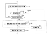
図7は、第2実施形態の異常時運転支援制御ルーチン(図6)における処理を変更する部分を表すフローチャートの一部である。この変形例では、図中における破線で囲んだ処理が追加されている。以下、この変形例を異常確定変形例と呼ぶ。
<Modification of abnormality determination timing>
FIG. 7 is a part of a flowchart showing a part for changing the process in the abnormal time driving support control routine (FIG. 6) of the second embodiment. In this modification, a process surrounded by a broken line in the drawing is added. Hereinafter, this modification is referred to as an abnormality fixed modification.
運転支援ECU10は、運転者の運転操作が検出されない場合には、車速SPDが車速閾値SPDrefにまで低下するまで自車両を第1目標減速度にて減速させる(S31,S16,S32)。そして、運転支援ECU10は、車速が車速SPDが車速閾値SPDref以下に達すると(S32:Yes)、ステップS17において、運転無操作状態が予め設定した閾値である第2時間以上継続したか否かについて判定する。
When the driver's driving operation is not detected, the driving
運転無操作状態の継続時間が第2時間未満である場合(S17:No)、運転支援ECU10は、その処理をステップS34に進めて、車速センサ16からの信号に基づいて取得される現時点の車速SPDで自車両を定速走行させるための指令信号をエンジンECU30及びブレーキECU40に出力する。これにより、自車両の走行状態は、それまでの減速走行から定速走行に切り替わる。尚、定速走行が継続される場合には、運転支援ECU10は、減速走行から定速走行に切り替わったときの車速を記憶し、その車速を維持させるとよい。
When the duration of the no-operation state is less than the second time (S17: No), the driving
運転支援ECU10は、自車両を定速走行させるための指令信号を出力すると、その処理をステップS16に戻す。こうした処理が繰り返され、運転無操作状態の継続時間が第2時間に到達すると(S17:Yes)、運転支援ECU10は、ステップS18において、運転者が異常状態にあるとの判定を確定する。
When the driving
この異常確定タイミング変形例によれば、運転者が異常状態にあるとの判定を確定させるまでの期間を確実に確保することができる。つまり、第1目標減速度α1での減速制御を開始した時の車速が低い場合には、減速制御の開始から早いタイミングで車速SPDが車速閾値SPDrefにまで低下してしまうが、この変形例によれば、そうした場合でも、運転支援ECU10は、運転無操作状態の継続時間が第2時間に到達するまで自車両を定速走行させて運転無操作状態の有無を確認する。このため、運転者の異常状態が高い精度にて判定された後に、異常時運転制御を開始させることができる。
According to this abnormality confirmation timing modification, it is possible to reliably ensure a period until the determination that the driver is in an abnormal state is confirmed. That is, when the vehicle speed when the deceleration control at the first target deceleration rate α1 is started is low, the vehicle speed SPD decreases to the vehicle speed threshold value SPDref at an early timing from the start of the deceleration control. Accordingly, even in such a case, the driving
<第3実施形態>
次に、第3実施形態の車両制御装置について説明する。第3実施形態の車両制御装置は、運転支援ECU10が、上述した第1実施形態、あるいは、第2実施形態の異常時運転支援制御ルーチンに代えて、図8あるいは図9に示す異常時運転支援制御ルーチンを実施する点においてのみ、上述した第1実施形態、あるいは、第2実施形態と相違する。
<Third Embodiment>
Next, the vehicle control apparatus of 3rd Embodiment is demonstrated. In the vehicle control apparatus of the third embodiment, the driving
第1実施形態および第2実施形態においては、運転者の手放し状態が第1時間継続されたときに、LKAの制御モードが「弱めモード」に設定されるように構成されているが、この第3実施形態においては、LKAが中断され、代わりに、LDAが実施されるように構成されている。運転支援ECU10は、操作スイッチ18によってLKAとLDAとの実行が選択されている場合には、図8に示す異常時運転支援制御ルーチンを実施し、操作スイッチ18によってLKAの実行が選択され、LDAの実行が選択されていない場合には、図9に示す異常時運転支援制御ルーチンを実施する。
In the first embodiment and the second embodiment, the LKA control mode is set to the “weak mode” when the driver's release state is continued for the first time. In the three embodiments, LKA is suspended and configured to perform LDA instead. When execution of LKA and LDA is selected by the
この図8に示す異常時運転支援制御ルーチンは、第2実施形態の異常時運転支援制御ルーチン(図6)のステップS12,ステップS15,ステップS19に代えて、ステップS41,ステップS42,ステップS43を組み込んだものである。また、図9に示す異常時運転支援制御ルーチンは、第2実施形態の異常時運転支援制御ルーチン(図6)のステップS12,ステップS15,ステップS19に代えて、ステップS51,ステップS42,ステップS52を組み込んだものである。他の処理については、第2実施形態と同一であるため、図面に共通のステップ符号を付して、その説明を省略、あるいは、簡単な説明に留める。尚、こうした処理の変更は、第1実施形態にも適用することもできる。 The abnormal driving support control routine shown in FIG. 8 replaces steps S12, S15, and S19 of the abnormal driving support control routine (FIG. 6) of the second embodiment with steps S41, S42, and S43. It is incorporated. In addition, the abnormal driving support control routine shown in FIG. 9 replaces steps S12, S15, and S19 of the abnormal driving support control routine (FIG. 6) of the second embodiment with steps S51, S42, and S52. Is incorporated. Since other processes are the same as those in the second embodiment, common step symbols are attached to the drawings, and the description thereof is omitted or only a brief description is given. Such processing changes can also be applied to the first embodiment.
運転支援ECU10は、操作スイッチ18によって、ACCと、LKAおよびLDAとの実行が選択されている場合に、図8に示す異常時運転支援制御ルーチンを開始する。運転支援ECU10は、ステップS41において、操作スイッチ18による設定どおり、LKAおよびLDAについてON設定、つまり、LKAおよびLDAを作動許可状態に設定する。運転支援ECU10は、LKAおよびLDAがON設定されている場合、自車両の走行レーンに対する位置に応じてLKAとLDAとを切り替えて実施するが、自車両が左右の白線に近づかないあいだはLKAを実施し、何らかの要因で自車両が左右の白線に近づいて車線の外に逸脱するおそれが生じた場合においてのみLDAを実施する。
When the
本ルーチンが起動した直後においては、LKAおよびLDAについてON設定されているため、ステップS41においては、その設定を変更する処理は行われない。従って、自車両は、基本的には、LKAによって目標走行ラインに沿って走行するように操舵制御される。 Immediately after this routine is started, ON is set for LKA and LDA, and therefore processing for changing the setting is not performed in step S41. Accordingly, the host vehicle is basically steered by the LKA so as to travel along the target travel line.
運転支援ECU10は、手放し時間が第1時間以上継続した場合(S13:Yes)、運転者が異常状態にあるとの仮の判定を行い(S14)、その処理をステップS42に進める。運転支援ECU10は、ステップS42において、LKAをOFF設定にする(換言すれば、LKAの制御量をゼロにまで低下させる)。LDAについてはON設定が維持される。これにより、目標走行ラインに沿って走行していた自車両は、目標走行ラインから外れるようになる。この場合、LDAが機能して、自車両が車線の外側(白線の外側)に逸脱しないように操舵制御される。このため、自車両は、左右の白線内をふらつきながら走行することになる。
When the hand release time continues for the first time or longer (S13: Yes), the driving
このため、運転能力を失っていない運転者に対してハンドル操作が促される。これにより、ハンドル操作を怠っていた運転者は、ハンドル操作を開始するとともに、LKAを過信しなくなる。また、例えば、自車両をふらつかせることによって、居眠りしていた運転者を目覚めさせることができる場合もある。 For this reason, steering operation is urged to the driver who has not lost driving ability. As a result, the driver who has neglected the steering wheel operation starts the steering wheel operation and does not overtrust LKA. In addition, for example, the driver who has fallen asleep can be awakened by wobbling the own vehicle.
続いて、運転支援ECU10は、ステップS31において、ACCを中止して、自車両を予め設定された一定の第1目標減速度α1にて減速させ、続くステップS16において、運転無操作状態であるかについて判定する。運転無操作状態である場合には、運転支援ECU10は、続くステップS32において、車速SPDが予め設定された車速閾値SPDref以下であるか否かについて判定する。
Subsequently, in step S31, the driving
車速SPDが車速閾値SPDrefを超えている場合(S32:No)、運転支援ECU10は、その処理をステップS31に戻す。このようにして、運転支援ECU10は、所定の演算周期でステップS31,S16,S32における処理を繰り返し実施する。
When the vehicle speed SPD exceeds the vehicle speed threshold value SPDref (S32: No), the driving
走行状態の変化(ふらつき、および、減速)に反応して、運転者が運転操作を再開した場合には、ステップS16の判定が「No」となって、その処理がステップS11に戻される。従って、運転者が異常状態にあるとの仮の判定が取り消され、運転者の状態は、「正常」に設定される。また、ステップS41において、LKAがON設定に戻される。これにより、自車両を目標走行ラインLdに沿って適性に走行させることができる。 When the driver resumes the driving operation in response to the change in the running state (staggering and deceleration), the determination in step S16 is “No”, and the process returns to step S11. Accordingly, the provisional determination that the driver is in an abnormal state is canceled, and the driver's state is set to “normal”. In step S41, LKA is returned to the ON setting. Thereby, the own vehicle can be appropriately traveled along the target travel line Ld.
一方、運転操作が検出されることなく、車速SPDが車速閾値SPDrefにまで低下すると(S32:Yes)、運転支援ECU10は、ステップS18において、運転者が異常状態にあるとの判定を確定させる(S18)とともに、ステップS43において、LKAをON設定に戻す。続いて、運転支援ECU10は、ステップS33からの処理を実施する。従って、自車両を目標走行ラインLdに沿って適性に走行させながら、第2目標減速度α2にて減速させて自車両を停止させることできる。
On the other hand, when the driving speed is decreased to the vehicle speed threshold value SPDref without detecting the driving operation (S32: Yes), the driving
次に、操作スイッチ18によってLKAの実行が選択され、LDAの実行が選択されていない場合について説明する。
Next, a case where execution of LKA is selected by the
運転支援ECU10は、操作スイッチ18により、ACCとLKAとの実行が選択され、LDAの実行が選択されていない場合に、図9に示す異常時運転支援制御ルーチンを開始する。運転支援ECU10は、ステップS51において、操作スイッチ18による設定どおり、LKAについてはON設定、LDAについてはOFF設定にする。この場合、運転支援ECU10は、LKAのみを実行する。これにより、自車両は目標走行ラインLdに沿って走行するように操舵制御される。
The driving
運転支援ECU10は、手放し時間が第1時間以上継続した場合(S13:Yes)、運転者が異常状態にあるとの仮の判定を行い(S14)、その処理をステップS42に進める。運転支援ECU10は、ステップS42において、LKAをOFF設定し、LDAをON設定する。これにより、LKAが中断され、LDAが開始される。従って、目標走行ラインに沿って走行していた自車両は、目標走行ラインから外れるようになる。この場合、LDAが機能して、自車両が車線の外側(白線の外側)に逸脱しないように操舵制御される。このため、自車両は、左右の白線内をふらつきながら走行することになる。
When the hand release time continues for the first time or longer (S13: Yes), the driving
このため、運転能力を失っていない運転者に対してハンドル操作が促される。これにより、ハンドル操作を怠っていた運転者は、ハンドル操作を開始するとともに、LKAを過信しなくなる。また、例えば、自車両をふらつかせることによって、居眠りしていた運転者を目覚めさせることができる場合もある。 For this reason, steering operation is urged to the driver who has not lost driving ability. As a result, the driver who has neglected the steering wheel operation starts the steering wheel operation and does not overtrust LKA. In addition, for example, the driver who has fallen asleep can be awakened by wobbling the own vehicle.
続いて、運転支援ECU10は、上述したステップS31,S16,S32における処理を繰り返し実施する。走行状態の変化(ふらつき、および、減速)に反応して、運転者が運転操作を再開した場合には、ステップS16の判定が「No」となって、その処理がステップS11に戻される。従って、運転者が異常状態にあるとの仮の判定が取り消され、運転者の状態は、「正常」に設定される。また、ステップS51において、操作スイッチ18によって設定されている通りに、LKAがON設定に戻され、LDAがOFF設定に戻される。これにより、自車両を目標走行ラインLdに沿って適性に走行させることができる。
Subsequently, the driving
一方、運転操作が検出されることなく、車速SPDが車速閾値SPDrefにまで低下すると(S32:Yes)、運転支援ECU10は、ステップS18において、運転者が異常状態にあるとの判定を確定させる(S18)とともに、ステップS52において、LKAをON設定に戻し、LDAをOFF設定に戻す。続いて、運転支援ECU10は、上述したステップS33からの処理を実施する。従って、自車両を目標走行ラインLdに沿って適性に走行させながら、第2目標減速度α2にて減速させて自車両を停止させることできる。
On the other hand, when the driving speed is decreased to the vehicle speed threshold value SPDref without detecting the driving operation (S32: Yes), the driving
以上説明した第3実施形態の車両制御装置によれば、運転者の手放し状態が第1時間継続されると、運転者が異常状態にあるとの仮の判定がなされて、LKAがOFF設定にされる。つまり、LKAの制御量がゼロにまで低減される。この場合、LDAについては、それまでOFF設定であればON設定に切り替えられる。これにより、自車両の操舵がLDAのみによって制御されることにより、自車両を車線内においてふらつかせることができる。この結果、第1、第2実施形態と同様に、運転者に対して手放し運転をさせないようにすることができる。また、運転者の異常判定精度が高くなった段階で異常時運転制御を実施することができる。これにより自車両を安全に停止させることができる。 According to the vehicle control device of the third embodiment described above, when the driver's hand-off state continues for the first time, a temporary determination that the driver is in an abnormal state is made, and LKA is set to OFF. Is done. That is, the LKA control amount is reduced to zero. In this case, the LDA is switched to the ON setting if it has been set to OFF until then. Thereby, the steering of the own vehicle is controlled only by the LDA, so that the own vehicle can be staggered in the lane. As a result, like the first and second embodiments, the driver can be prevented from letting go. In addition, the abnormality-time operation control can be performed when the abnormality determination accuracy of the driver is increased. Thereby, the own vehicle can be stopped safely.
<白線認識不良対応変形例>
運転支援ECU10は、カメラ装置17bから送信された画像データに基づいて自車両が走行しているレーンの左右の白線を認識し、この白線に基づいてLKAおよびLDAを実施する。そのため、白線の認識状態が悪い場合に、上述したように「仮異常」と判定されている時に、LKAの制御量を低減した場合には、自車両がレーンから逸脱するおそれがある。また、白線の認識状態が悪い場合には、もともと自車両がレーン内をふらつきやすい。そこで、運転支援ECU10は、白線の認識レベルを演算し、この認識レベルが閾値以下である場合には、LKAの制御量を低減することを中止する。
<Modification for white line recognition failure>
The driving
例えば、運転支援ECU10は、第1実施形態あるいは第2実施形態の異常時運転支援制御ルーチン(図5あるいは図6)において、図10に示すように、ステップS15を実施する前の処理として、ステップS61,S62の処理を行う。この場合、運転支援ECU10は、ステップS61において、白線の認識レベルXを演算し、続くステップS62において、認識レベルXが閾値Xrefより高いか否かについて判定する。この認識レベルXは、例えば、認識できている白線(LLおよびLR)の距離を用いればよい。運転支援ECU10は、認識レベルXが予め設定した閾値Xrefより高ければ(S62:Yes)、その処理をステップS15に進めてLKAを「弱めモード」に設定する。一方、認識レベルXが閾値Xref以下であれば(S62:No)、ステップS15の処理をスキップする。これにより、自車両がレーンから逸脱することを抑制することができる。同様に、第3実施形態の異常時運転支援制御ルーチン(図8および図9)においは、図11に示すように、運転支援ECU10は、ステップS42を実施する前の処理として、ステップS61,S62の処理を行えばよい。
For example, as shown in FIG. 10, the driving
<第4実施形態>
次に、第4実施形態の車両制御装置について説明する。この第4実施形態では、運転支援ECU10は、LKAの制御モードの切り替え、減速制御の切り替え等の処理に加えて、運転者への警告、周囲への注意喚起等の処理を実施する。この第4実施形態においては、運転支援ECU10の実施する異常時運転支援制御処理について、図12に示すタイミングチャートを用いて説明する。尚、上述した第1〜第3実施形態と同様な処理に関しては、その具体的な方法、および、作用効果について、その説明を省略、あるいは、簡単な説明に留める。
<Fourth embodiment>
Next, a vehicle control device according to a fourth embodiment will be described. In the fourth embodiment, the driving
運転支援ECU10は、LKAとACCとを実行しているときに、操舵ハンドルSWが操作されていない状態(手放し状態)を検出すると、その検出した時刻t1から手放し継続時間を計測する。そして、運転支援ECU10は、手放し状態が所定時間(例えば、5秒間)継続した時点である時刻t2から手放し警告を開始する。この場合、運転支援ECU10は、警報ECU80に対して手放し警告指令を出力する。これにより警報ECU80は、操舵ハンドルSWの保持を促すマークを表示器82に表示する。
When the driving
運転支援ECU10は、こうした手放し警告を行ったにもかかわらず手放し状態が所定時間(例えば、2秒間)継続した場合には、その時点である時刻t3において、運転者が異常状態にあるとの仮の判定を行う。この仮の判定に基づいて、運転支援ECU10は、LKAの制御モードを「通常モード」から「弱めモード」に切り替える。この時刻t1から時刻t3までの経過時間(例えば、7秒(5秒+2秒))が、第1〜第3実施形態における第1時間に相当する。図12の最下段には、走行レーンにおける自車両の走行位置の変化を表す。この場合、時刻t3から自車両が車線内においてふらつき始める。
If the hand-off state continues for a predetermined time (for example, 2 seconds) even though such a hand-off warning is given, the driving
また、運転支援ECU10は、時刻t3において、警報ECU80に対して第1異常警告指令を出力する。これにより警報ECU80は、操舵ハンドルSWの保持を促すマークを表示器82に表示するとともに、ブザー81を第1周期にて鳴動させる。つまり、発音状態と、発音停止状態とを第1周期で交互に繰り返す警告音をブザー81発生させる。こうした運転者に対する警告を第1異常警告と呼ぶ。
Further, the driving
運転支援ECU10は、運転者が異常状態にあるとの仮の判定を行った時刻t3から、運転無操作状態であるか否かについて所定の演算周期で繰り返し判定し、運転無操作状態が所定時間(例えば、30秒)継続した場合には、その時点である時刻t4において、それまで実行していたACCを中止して、第1減速制御を開始する。この第1減速制御は、自車両を第1目標減速度α1にて減速させる制御である。
The driving
また、運転支援ECU10は、時刻t4において、警報ECU80に対して第2異常警告指令を出力する。これにより警報ECU80は、「運転してください」というメッセージを表示器82に表示するとともに、ブザー81を鳴動させる。このブザー音は、第1異常警告で用いられるブザー音よりも大きな音量で、かつ、第1周期よりも短い第2周期で鳴動される。こうした運転者に対する警告を第2異常警告と呼ぶ。尚、このメッセージについては、例えば、図示しないスピーカを使って音声アナウンスにより行ってもよい。
Further, the driving
運転支援ECU10は、第2異常警告を開始した時刻t4から、更に、運転無操作状態が所定時間(例えば、30秒)継続した場合には、その時点である時刻t5において、運転者が異常状態にあるという判定を確定させる。異常状態の判定が確定した場合、運転支援ECU10は、LKAの制御モードを「弱めモード」から「通常モード」に切り替える。また、運転支援ECU10は、減速制御を第1減速制御から第2減速制御に切り替える。つまり、目標減速度を第1減速度α1から第2減速度α2に切り替えて、自車両を停止させるべく減速させる。これにより、自車両は目標走行ラインLdに沿って減速走行する。この第1減速度α1および第2減速度α2は、第2実施形態と同様な値に設定されている。
When the driving no-operation state continues for a predetermined time (for example, 30 seconds) from the time t4 when the second abnormality warning is started, the driving
また、運転支援ECU10は、時刻t5において、警報ECU80に対して減速停止警告指令を出力する。これにより警報ECU80は、「停止します」というメッセージを表示器82に表示するとともに、連続音にてブザー81を鳴動させる。このブザー音の音量は、第2異常警告で用いられるブザー音の音量よりも大きい。こうした運転者に対する警告を減速停止警告と呼ぶ。尚、このメッセージについても、例えば、図示しないスピーカを使って音声アナウンスにより行ってもよい。
In addition, the driving
また、運転支援ECU10は、時刻t5において、メータECU70に対して減速停止注意指令を出力する。これによりメータECU70は、ストップランプ72を点灯させるとともに、ハザードランプ71を点滅させる。
Further, the driving
こうして第2減速制御によって自車両が停止すると、運転支援ECU10は、LKA、および、第2減速制御を終了するとともに、警報ECU80に対して減速停止警告終了指令を出力する。これにより、減速停止警告が終了される。尚、減速停止警告については、自車両が停止した後も継続させてもよい。
When the host vehicle is thus stopped by the second deceleration control, the driving
また、運転支援ECU10は、自車両が停止すると、メータECU70に対してストップランプ消灯指令を出力する。これによりストップランプ72が消灯する。この場合、ハザードランプ71の点滅は継続される。
Further, when the host vehicle stops, the driving
更に、運転支援ECU10は、自車両が停止すると、電動パーキングブレーキECU50に対して電動パーキングブレーキ(EPB)の作動指令を出力するとともに、ボディECU90に対してドアロック装置91のロック解除指令を出力する。これにより、電動パーキングブレーキが作動状態となり、ドアロック装置91がアンロック状態となる。従って、自車両を安定的に停止状態に維持することができるとともに、ドアを開けて運転者を救出することが可能となる。尚、運転支援ECU10は、予め設定された所定の操作が行われたときに、運転者が異常状態であるとの判定を解除する。
Further, when the host vehicle stops, the driving
運転支援ECU10は、こうした異常時運転支援制御処理を実施している状況において、例えば、手放し警告を行っているときに、操舵ハンドルSWの操作が検出された場合(操舵トルクTra≠0)、手放し警告を終了するとともに、計測していた手放し継続時間をゼロクリアする。また、運転支援ECU10は、第1異常警告を行っている状況(時刻t3〜時刻t4)において、運転操作が検出された場合には、運転者の異常判定を「正常」に設定して、計測していた無操作継続時間をゼロクリアするとともに、LKAの制御モードを「通常モード」に戻して、第1異常警告を終了する。
In a situation where the driving support control process at the time of such an abnormality is performed, the driving
また、運転支援ECU10は、第2異常警告を行っている状況(時刻t4〜時刻t5)において、運転操作が検出された場合には、運転者の異常判定を「正常」に設定して、計測していた無操作継続時間をゼロクリアするとともに、LKAの制御モードを「通常モード」に戻して、第2異常警告を終了する。また、第1減速制御を終了する。
In addition, the driving
また、運転支援ECU10は、運転者が異常状態にあるとの判定が確定する前であれば、運転操作に応じた運転を許容する。しかし、運転者が異常状態にあるとの判定を確定した後(時刻t5以降)においては、運転支援ECU10は、運転操作が検出された場合であっても、第2減速制御を継続して自車両を停止させる。従って、運転支援ECU10は、運転者のアクセル操作が検出されても、アクセルペダルの操作に基づく加速要求を無効化(無視)する。また、運転支援ECU10は、減速停止警告、ストップランプ72の点灯、および、ハザードランプ71の点滅も継続する。
Further, the driving
以上説明した第4実施形態の車両制御装置によれば、運転無操作時間の経過に合わせて、減速制御、運転者への警告、および、周囲への注意喚起の形態が切り替えられる。従って、減速制御、運転者への警告、および、周囲への注意喚起を適切に実施することができる。 According to the vehicle control device of the fourth embodiment described above, the modes of deceleration control, warning to the driver, and alerting to the surroundings are switched in accordance with the elapse of the no-operation time. Accordingly, deceleration control, warning to the driver, and alerting to the surroundings can be appropriately performed.
尚、上述した手放し警告、第1異常警告、第2異常警告、減速停止警告、ストップランプ72の点灯、ハザードランプ71の点滅、ドアロックの解除、および、電動パーキングブレーキの作動については、第1〜第3実施形態においても適用できるものである。例えば、ステップS13の後半の期間において、手放し警告を行うとよい。また、ステップS16の判定が繰り返し実施されている期間において、第1異常警告あるいは第2異常警告を行うとよい。また、ステップS21の判定が繰り返し実施されている期間において、減速停止警告、ストップランプ72の点灯、および、ハザードランプ71の点滅を行うとよい。また、自車両が停止した時点(ステップS22において「Yes」と判定された時点)において、ドアロックの解除、および、電動パーキングブレーキの作動を行うとよい。
The first release warning, the first abnormality warning, the second abnormality warning, the deceleration stop warning, the
以上、本実施形態に係る車両制御装置について説明したが、本発明は上記実施形態および変形例に限定されるものではなく、本発明の目的を逸脱しない限りにおいて種々の変更が可能である。 Although the vehicle control apparatus according to the present embodiment has been described above, the present invention is not limited to the above-described embodiment and modifications, and various modifications can be made without departing from the object of the present invention.
例えば、異常確定タイミング変形例については、第2実施形態に限らず、第3実施形態あるいは第4実施形態にも適用することができる。例えば、第3実施形態では、ステップS32とステップS18との間に、図7に示すステップS17およびステップS34の処理を追加すればよい。 For example, the abnormality determination timing modification can be applied not only to the second embodiment but also to the third embodiment or the fourth embodiment. For example, in the third embodiment, steps S17 and S34 shown in FIG. 7 may be added between step S32 and step S18.
また、各実施形態においては、LKA及びACCの両方が実施されているときに、異常時運転支援制御ルーチンが実施されるが、ACCについては、必ずしも実施されている必要はない。 Moreover, in each embodiment, when both LKA and ACC are implemented, the driving assistance control routine at the time of abnormality is implemented, but ACC does not necessarily need to be implemented.
また、第1〜第3実施形態においては、運転者が異常状態にあるとの判定を確定させた後においても、ステップS21において、運転無操作の判定を行って、運転操作が検出された場合に、異常時運転制御(減速制御)を中止して通常状態に戻すが、必ずしも、そのようにする必要はない。例えば、ステップS21の判定処理を省略してもよい。つまり、第4実施形態のように、運転者が異常状態にあるとの判定を確定させた後においては、運転操作の有無に関係なく、自車両が停止するまで減速制御を継続するようにしてもよい。 Further, in the first to third embodiments, even after the determination that the driver is in an abnormal state is confirmed, in step S21, it is determined that there is no driving operation and a driving operation is detected. In addition, although the abnormal operation control (deceleration control) is stopped and returned to the normal state, it is not always necessary to do so. For example, the determination process in step S21 may be omitted. That is, after the determination that the driver is in an abnormal state is confirmed as in the fourth embodiment, the deceleration control is continued until the host vehicle stops regardless of the presence or absence of the driving operation. Also good.
また、第4実施形態の変形例として、第1〜第3実施形態のように、運転者が異常状態にあるとの判定を確定させた後においても、運転無操作の判定を行って、運転操作が検出された場合に、第2減速制御、減速停止警告、ストップランプ72の点灯、および、ハザードランプ71の点滅を中止して通常状態に戻すようにしてもよい。
Further, as a modification of the fourth embodiment, as in the first to third embodiments, even after the determination that the driver is in an abnormal state is confirmed, the determination of no operation is performed, and the driving is performed. When the operation is detected, the second deceleration control, the deceleration stop warning, the lighting of the
また、各実施形態においては、運転者が異常状態にあると仮に判定したときに、LKAの制御モードを「弱めモード」に設定して、LKAの制御量を小さな値に変更するが、それに代えて、自車両が車線から逸脱しない範囲で、目標走行ラインLdを所定距離だけ道路幅方向にオフセットさせるように変更してもよい。例えば、左右白線の中央位置が目標走行ラインLdとして設定されている場合、運転支援ECU10は、その目標走行ラインLdを所定距離だけ右側あるいは左側にずらした走行ラインを仮異常時目標走行ラインに設定する。従って、本来の目標走行ラインLdに沿って自車両が走行するLKAの性能を低下させた状態で、自車両を車線内にて走行させることができる。このようにすることで、運転者にとって所望となる走行ラインを自車両が走行しなくなるため、ハンドル操作を怠けていた運転者に対して、ハンドル操作を促すことができる。
In each embodiment, when it is determined that the driver is in an abnormal state, the LKA control mode is set to “weak mode” and the LKA control amount is changed to a small value. Thus, the target travel line Ld may be changed to be offset in the road width direction by a predetermined distance within a range in which the host vehicle does not deviate from the lane. For example, when the center position of the left and right white lines is set as the target travel line Ld, the driving
10…運転支援ECU、14…操舵角センサ、15…操舵トルクセンサ、16…車速センサ、17a…レーダセンサ、17b…カメラ装置、18…操作スイッチ、19…確認ボタン、30…エンジンECU、40…ブレーキECU、60…ステアリングECU、61…モータドライバ、62…転舵用モータ、SW…操舵ハンドル、SPD…車速、α…目標減速度、α1…第1目標減速度、α2…第2目標減速度、θLKA*…目標舵角、K1、K2、K3…制御ゲイン、Ld…目標走行ライン。
DESCRIPTION OF
Claims (5)
前記車線維持支援手段によって前記操舵制御が行われている状況において、前記運転者が操舵ハンドルの操作をしていないと推定される手放し状態が予め設定した仮異常判定時間以上継続したか否かを判定し、前記手放し状態が前記仮異常判定時間以上継続したときに、前記運転者が前記車両を運転する能力を失っている異常状態にあるとの仮の判定を行う仮判定手段と、
前記仮判定手段によって前記仮の判定が行われた場合に、前記車両が前記目標走行ラインに沿って走行する車線維持性能を低下させた状態で車線内を走行するように、前記仮の判定が行われる前に比べて、前記車線維持支援制御量を低減する制御量変更手段と、
前記制御量変更手段によって前記車線維持支援制御量が変更された後において、前記運転者が前記異常状態にあると推定される状態が予め設定した設定タイミングまで継続したか否かを判定し、前記運転者が前記異常状態にあると推定される状態が前記設定タイミングまで継続したときに、前記運転者が前記異常状態にあるとの判定を確定させる異常確定手段と、
前記運転者が前記異常状態にあるとの判定が確定したことに基づいて、危険回避用の運転制御である異常時運転制御を実施する異常時運転制御手段と
を備え、
前記車線維持支援手段は、前記目標走行ラインの曲率に基づいて演算される曲率制御量と、前記目標走行ラインと前記車両の位置とにおける道路幅方向の距離偏差に基づいて演算される距離偏差制御量と、前記目標走行ラインの方向と前記車両の向きとのずれ角に基づいて演算されるヨー角偏差制御量とを含んだ車線維持支援制御量を演算し、
前記制御量変更手段は、前記曲率制御量に比べて、前記距離偏差制御量と前記ヨー角偏差制御量との低減度合を大きくして、前記車線維持支援制御量を低減するように構成されている車両制御装置。 Recognizing the road ahead of the vehicle, setting a target travel line, calculating a lane maintenance support control amount for performing driving support for the driver so that the vehicle travels along the target travel line, and the lane Lane maintenance support means for performing steering control of the vehicle based on the maintenance support control amount;
In the situation where the steering control is being performed by the lane keeping assist means, it is determined whether or not the hand-off state estimated that the driver is not operating the steering wheel has continued for a preset temporary abnormality determination time or more. A temporary determination means for performing a temporary determination that the driver has lost an ability to drive the vehicle when the release state continues for the temporary abnormality determination time or longer, and
If the determination of the temporary is performed by the temporary determination means, wherein such vehicle is traveling in lane in a state with a reduced lane keeping ability to travel along said target traveling line, the determination of the temporary A control amount changing means for reducing the lane keeping support control amount compared to before being performed ;
After the lane keeping assist control amount is changed by the control amount changing means, it is determined whether or not the state where the driver is estimated to be in the abnormal state has continued until a preset setting timing, An abnormality confirming means for confirming that the driver is in the abnormal state when the state in which the driver is estimated to be in the abnormal state continues until the set timing;
Based on the determination that the driver is in the abnormal state, the abnormal-time operation control means for performing the abnormal-time operation control, which is the operation control for avoiding danger,
With
The lane keeping support means is a distance deviation control calculated based on a curvature control amount calculated based on the curvature of the target travel line and a distance deviation in the road width direction between the target travel line and the position of the vehicle. A lane keeping assist control amount including a quantity and a yaw angle deviation control amount calculated based on a deviation angle between the direction of the target travel line and the direction of the vehicle,
The control amount changing means is configured to reduce the lane keeping assist control amount by increasing the degree of reduction of the distance deviation control amount and the yaw angle deviation control amount as compared with the curvature control amount. vehicle control device it is.
前記異常時運転制御手段は、前記車両を停止させるべく目標減速度にて減速させるように構成されている車両制御装置。 The vehicle control device according to claim 1,
The abnormal operation control means is a vehicle control device configured to decelerate at a target deceleration to stop the vehicle.
前記異常時運転制御手段は、前記車線維持支援制御量を、それまでの前記車線維持性能を低下させた車線維持支援制御量から、前記車線維持性能を向上させた車線維持支援制御量に変更するように構成されている車両制御装置。 The vehicle control device according to claim 1 or 2,
The abnormal-time operation control means changes the lane keeping support control amount from the lane keeping support control amount that has lowered the lane keeping performance so far to the lane keeping support control amount that has improved the lane keeping performance. A vehicle control device configured as described above.
前記制御量変更手段は、前記距離偏差制御量と前記ヨー角偏差制御量とを低減し、前記曲率制御量については低減しないように構成されている車両制御装置。 In the vehicle control device according to any one of claims 1 to 3 ,
The control amount changing means is configured to reduce the distance deviation control amount and the yaw angle deviation control amount and not to reduce the curvature control amount .
前記制御量変更手段は、前記車線維持支援手段が前記道路を認識できる認識レベルが閾値以下である場合には、前記車線維持支援制御量の変更を実施しないように構成されている車両制御装置。 The vehicle control device according to claim 4 , wherein
The control amount changing means is configured to not change the lane keeping support control amount when a recognition level at which the lane keeping support means can recognize the road is equal to or less than a threshold value .
Priority Applications (4)
| Application Number | Priority Date | Filing Date | Title |
|---|---|---|---|
| JP2016153579A JP6583183B2 (en) | 2016-08-04 | 2016-08-04 | Vehicle control device |
| US15/647,768 US10377366B2 (en) | 2016-08-04 | 2017-07-12 | Vehicle control device |
| DE102017117244.0A DE102017117244A1 (en) | 2016-08-04 | 2017-07-31 | Vehicle control unit |
| CN201710650812.4A CN107685729B (en) | 2016-08-04 | 2017-08-02 | Vehicle control device |
Applications Claiming Priority (1)
| Application Number | Priority Date | Filing Date | Title |
|---|---|---|---|
| JP2016153579A JP6583183B2 (en) | 2016-08-04 | 2016-08-04 | Vehicle control device |
Publications (2)
| Publication Number | Publication Date |
|---|---|
| JP2018022365A JP2018022365A (en) | 2018-02-08 |
| JP6583183B2 true JP6583183B2 (en) | 2019-10-02 |
Family
ID=60996728
Family Applications (1)
| Application Number | Title | Priority Date | Filing Date |
|---|---|---|---|
| JP2016153579A Active JP6583183B2 (en) | 2016-08-04 | 2016-08-04 | Vehicle control device |
Country Status (4)
| Country | Link |
|---|---|
| US (1) | US10377366B2 (en) |
| JP (1) | JP6583183B2 (en) |
| CN (1) | CN107685729B (en) |
| DE (1) | DE102017117244A1 (en) |
Families Citing this family (35)
| Publication number | Priority date | Publication date | Assignee | Title |
|---|---|---|---|---|
| JP6544305B2 (en) * | 2016-06-24 | 2019-07-17 | トヨタ自動車株式会社 | Vehicle travel control device |
| US11164459B2 (en) * | 2017-03-14 | 2021-11-02 | Hyundai Mobis Co., Ltd. | Apparatus and method of safety support for vehicle |
| US10446031B2 (en) | 2017-03-14 | 2019-10-15 | Hyundai Mobis Co., Ltd. | Apparatus and method of safety support for vehicle |
| EP3678109B1 (en) * | 2017-08-30 | 2023-05-03 | Nissan Motor Co., Ltd. | Position correction method for driving-assist vehicle and position error correction device |
| JP6926957B2 (en) * | 2017-11-02 | 2021-08-25 | トヨタ自動車株式会社 | Lane change support device |
| KR102005900B1 (en) * | 2017-11-30 | 2019-08-01 | 주식회사 만도 | Method and apparatus of electric power steering adjusting assist torque by chance of head-on collision and side collision |
| JP6900915B2 (en) | 2018-01-24 | 2021-07-07 | トヨタ自動車株式会社 | Autonomous driving system |
| JP6848912B2 (en) * | 2018-03-23 | 2021-03-24 | 株式会社デンソー | Status determination device, status determination program and computer readable continuous tangible recording medium |
| JP7133337B2 (en) * | 2018-04-10 | 2022-09-08 | 本田技研工業株式会社 | VEHICLE CONTROL DEVICE, VEHICLE CONTROL METHOD, AND PROGRAM |
| US11084490B2 (en) * | 2018-04-11 | 2021-08-10 | Hyundai Motor Company | Apparatus and method for controlling drive of vehicle |
| JP2020097266A (en) * | 2018-12-17 | 2020-06-25 | トヨタ自動車株式会社 | Travel control device of vehicle |
| JP6714116B1 (en) * | 2019-02-06 | 2020-06-24 | 三菱電機株式会社 | Vehicle control device and vehicle control method |
| JP7307558B2 (en) * | 2019-03-06 | 2023-07-12 | 株式会社Subaru | Vehicle driving control system |
| JP7205773B2 (en) | 2019-03-27 | 2023-01-17 | スズキ株式会社 | Vehicle travel control device |
| JP7232099B2 (en) * | 2019-03-28 | 2023-03-02 | 株式会社Subaru | driving support system |
| JP7075908B2 (en) * | 2019-03-28 | 2022-05-26 | 本田技研工業株式会社 | Vehicle control system |
| JP7226160B2 (en) * | 2019-07-16 | 2023-02-21 | トヨタ自動車株式会社 | Vehicle running control device |
| JP7348775B2 (en) * | 2019-08-28 | 2023-09-21 | 株式会社Subaru | Vehicle lane departure prevention control device |
| JP7327032B2 (en) * | 2019-09-19 | 2023-08-16 | スズキ株式会社 | vehicle controller |
| KR20210042188A (en) * | 2019-10-08 | 2021-04-19 | 현대자동차주식회사 | Vehicle and method for controlling thereof |
| JP7149918B2 (en) * | 2019-10-16 | 2022-10-07 | 本田技研工業株式会社 | Contact avoidance support device for vehicles |
| KR20210100241A (en) * | 2020-02-05 | 2021-08-17 | 현대모비스 주식회사 | Lamp system for traffic lane indication using navigation link and method for traffic lane indication thereof |
| JP7294194B2 (en) * | 2020-03-11 | 2023-06-20 | いすゞ自動車株式会社 | Safe driving judgment device |
| JP7339203B2 (en) | 2020-04-10 | 2023-09-05 | トヨタ自動車株式会社 | vehicle controller |
| CN111717210B (en) * | 2020-06-01 | 2022-11-11 | 重庆大学 | Detection method for separation of driver from steering wheel in relative static state of hands |
| JP7318595B2 (en) * | 2020-06-29 | 2023-08-01 | トヨタ自動車株式会社 | vehicle controller |
| KR20220028709A (en) * | 2020-08-31 | 2022-03-08 | 현대모비스 주식회사 | Driving control method and system for vehicles |
| US11738748B2 (en) * | 2020-10-16 | 2023-08-29 | GM Global Technology Operations LLC | Method and apparatus for adaptive lane keep assist for assisted driving |
| CN112477859B (en) * | 2020-10-21 | 2022-03-15 | 中国汽车技术研究中心有限公司 | Lane keeping assist method, apparatus, device and readable storage medium |
| CN112389448B (en) * | 2020-11-23 | 2022-07-01 | 重庆邮电大学 | Abnormal driving behavior identification method based on vehicle state and driver state |
| KR20220094298A (en) * | 2020-12-28 | 2022-07-06 | 주식회사 에이치엘클레무브 | Vehicle and vehicle driving assistance control method |
| CN113119967B (en) * | 2021-04-30 | 2022-07-15 | 东风汽车集团股份有限公司 | Intelligent driving assisting method, device, equipment and storage medium |
| CN113119983A (en) * | 2021-05-07 | 2021-07-16 | 恒大新能源汽车投资控股集团有限公司 | Vehicle safety control method and device and vehicle |
| WO2023084767A1 (en) * | 2021-11-15 | 2023-05-19 | 日産自動車株式会社 | Driving control method and driving control device |
| JP7461989B2 (en) | 2022-06-23 | 2024-04-04 | 本田技研工業株式会社 | Driving assistance device, driving assistance method, and program |
Family Cites Families (27)
| Publication number | Priority date | Publication date | Assignee | Title |
|---|---|---|---|---|
| JPS4929777A (en) | 1972-07-18 | 1974-03-16 | ||
| JP2001266163A (en) * | 2000-03-17 | 2001-09-28 | Nissan Motor Co Ltd | On-vehicle image processor |
| JP2005088806A (en) * | 2003-09-18 | 2005-04-07 | Hitachi Unisia Automotive Ltd | Steering control device |
| JP4349210B2 (en) | 2004-06-02 | 2009-10-21 | トヨタ自動車株式会社 | Driving assistance device |
| JP4172434B2 (en) | 2004-07-30 | 2008-10-29 | トヨタ自動車株式会社 | Inter-vehicle distance control device |
| JP4507976B2 (en) | 2005-05-11 | 2010-07-21 | トヨタ自動車株式会社 | Vehicle travel control device |
| JP4929777B2 (en) | 2006-03-23 | 2012-05-09 | トヨタ自動車株式会社 | Vehicle travel control device |
| JP5045374B2 (en) | 2007-08-28 | 2012-10-10 | 株式会社豊田中央研究所 | Operating state determination device |
| JP2009190464A (en) | 2008-02-12 | 2009-08-27 | Toyota Motor Corp | Lane keeping support system |
| JP5359085B2 (en) * | 2008-03-04 | 2013-12-04 | 日産自動車株式会社 | Lane maintenance support device and lane maintenance support method |
| JP5151625B2 (en) * | 2008-04-01 | 2013-02-27 | トヨタ自動車株式会社 | Steering support device |
| JP4702398B2 (en) | 2008-05-26 | 2011-06-15 | トヨタ自動車株式会社 | Driving assistance device |
| JP5220492B2 (en) | 2008-06-27 | 2013-06-26 | 株式会社豊田中央研究所 | Lane maintenance support device |
| JP2008273521A (en) * | 2008-08-18 | 2008-11-13 | Toyota Motor Corp | Automatic driving device for moving body |
| JP5136314B2 (en) * | 2008-09-16 | 2013-02-06 | トヨタ自動車株式会社 | Lane recognition device |
| DE112011103834T8 (en) * | 2010-11-19 | 2013-09-12 | Magna Electronics, Inc. | Lane departure warning and lane centering |
| JP5747787B2 (en) * | 2011-11-04 | 2015-07-15 | トヨタ自動車株式会社 | Lane recognition device |
| US9168953B2 (en) * | 2011-11-08 | 2015-10-27 | Toyota Jidosha Kabushiki Kaisha | Vehicle travel track control device |
| JP5549721B2 (en) | 2011-12-26 | 2014-07-16 | 株式会社デンソー | Driver monitor device |
| JP2014091380A (en) * | 2012-11-01 | 2014-05-19 | Toyota Motor Corp | Driving support device |
| JP6158523B2 (en) | 2013-02-04 | 2017-07-05 | トヨタ自動車株式会社 | Inter-vehicle distance control device |
| DE102013009400A1 (en) * | 2013-06-04 | 2014-12-04 | Volkswagen Aktiengesellschaft | Emergency assistance for vehicle guidance |
| JP6134276B2 (en) * | 2014-03-03 | 2017-05-24 | 株式会社Soken | Traveling line recognition device |
| JP6394251B2 (en) * | 2014-10-02 | 2018-09-26 | トヨタ自動車株式会社 | Vehicle control device |
| KR101621747B1 (en) * | 2014-12-15 | 2016-05-17 | 주식회사 만도 | Electric Steering Apparatus and Controlling Method of the Same |
| JP2016196285A (en) * | 2015-04-03 | 2016-11-24 | 株式会社デンソー | Travel controlling device and travel controlling method |
| JP6455456B2 (en) | 2016-02-16 | 2019-01-23 | トヨタ自動車株式会社 | Vehicle control device |
-
2016
- 2016-08-04 JP JP2016153579A patent/JP6583183B2/en active Active
-
2017
- 2017-07-12 US US15/647,768 patent/US10377366B2/en active Active
- 2017-07-31 DE DE102017117244.0A patent/DE102017117244A1/en active Pending
- 2017-08-02 CN CN201710650812.4A patent/CN107685729B/en active Active
Also Published As
| Publication number | Publication date |
|---|---|
| CN107685729A (en) | 2018-02-13 |
| US10377366B2 (en) | 2019-08-13 |
| US20180037216A1 (en) | 2018-02-08 |
| DE102017117244A1 (en) | 2018-02-08 |
| JP2018022365A (en) | 2018-02-08 |
| CN107685729B (en) | 2020-05-19 |
Similar Documents
| Publication | Publication Date | Title |
|---|---|---|
| JP6583183B2 (en) | Vehicle control device | |
| JP6455456B2 (en) | Vehicle control device | |
| US10000236B2 (en) | Vehicle control device | |
| KR101965054B1 (en) | Vehicle running control apparatus | |
| JP6497349B2 (en) | Vehicle travel control device | |
| CN107539320B (en) | Vehicle travel control device | |
| JP6489080B2 (en) | Vehicle control device | |
| JP6544305B2 (en) | Vehicle travel control device | |
| US20180037226A1 (en) | Vehicle traveling control apparatus | |
| US10384540B2 (en) | Vehicle traveling control apparatus | |
| JP6443406B2 (en) | Vehicle alarm control device | |
| JP2018020693A (en) | Vehicle travel control device | |
| JP2017190047A (en) | Vehicle travel control apparatus | |
| US10800410B2 (en) | Driving support device | |
| JP2018001932A (en) | Vehicle control device | |
| US20180037200A1 (en) | Vehicle traveling control apparatus | |
| JP7380441B2 (en) | Vehicle control device |
Legal Events
| Date | Code | Title | Description |
|---|---|---|---|
| A621 | Written request for application examination |
Free format text: JAPANESE INTERMEDIATE CODE: A621 Effective date: 20180221 |
|
| A131 | Notification of reasons for refusal |
Free format text: JAPANESE INTERMEDIATE CODE: A131 Effective date: 20181225 |
|
| A977 | Report on retrieval |
Free format text: JAPANESE INTERMEDIATE CODE: A971007 Effective date: 20181220 |
|
| A521 | Request for written amendment filed |
Free format text: JAPANESE INTERMEDIATE CODE: A523 Effective date: 20190206 |
|
| TRDD | Decision of grant or rejection written | ||
| A01 | Written decision to grant a patent or to grant a registration (utility model) |
Free format text: JAPANESE INTERMEDIATE CODE: A01 Effective date: 20190806 |
|
| A61 | First payment of annual fees (during grant procedure) |
Free format text: JAPANESE INTERMEDIATE CODE: A61 Effective date: 20190819 |
|
| R151 | Written notification of patent or utility model registration |
Ref document number: 6583183 Country of ref document: JP Free format text: JAPANESE INTERMEDIATE CODE: R151 |